US7213905B2 - Liquid ejecting device - Google Patents
Liquid ejecting device Download PDFInfo
- Publication number
- US7213905B2 US7213905B2 US11/109,000 US10900005A US7213905B2 US 7213905 B2 US7213905 B2 US 7213905B2 US 10900005 A US10900005 A US 10900005A US 7213905 B2 US7213905 B2 US 7213905B2
- Authority
- US
- United States
- Prior art keywords
- liquid
- ink
- energy
- nozzle
- delivered
- Prior art date
- Legal status (The legal status is an assumption and is not a legal conclusion. Google has not performed a legal analysis and makes no representation as to the accuracy of the status listed.)
- Expired - Fee Related
Links
- 239000007788 liquid Substances 0.000 title claims abstract description 319
- 230000004044 response Effects 0.000 claims abstract description 24
- 238000010438 heat treatment Methods 0.000 abstract description 179
- 238000000034 method Methods 0.000 abstract description 42
- 238000004904 shortening Methods 0.000 abstract description 3
- 238000009826 distribution Methods 0.000 description 14
- 230000004048 modification Effects 0.000 description 14
- 238000012986 modification Methods 0.000 description 14
- 230000008859 change Effects 0.000 description 8
- 238000010586 diagram Methods 0.000 description 8
- 230000015572 biosynthetic process Effects 0.000 description 7
- 239000000758 substrate Substances 0.000 description 6
- 230000004888 barrier function Effects 0.000 description 5
- 238000005516 engineering process Methods 0.000 description 5
- 238000004519 manufacturing process Methods 0.000 description 5
- 230000008569 process Effects 0.000 description 4
- 239000004065 semiconductor Substances 0.000 description 4
- 238000012935 Averaging Methods 0.000 description 3
- PXHVJJICTQNCMI-UHFFFAOYSA-N Nickel Chemical compound [Ni] PXHVJJICTQNCMI-UHFFFAOYSA-N 0.000 description 2
- 230000006866 deterioration Effects 0.000 description 2
- 230000000694 effects Effects 0.000 description 2
- 239000012472 biological sample Substances 0.000 description 1
- 238000009835 boiling Methods 0.000 description 1
- 239000004020 conductor Substances 0.000 description 1
- 238000005323 electroforming Methods 0.000 description 1
- 239000000463 material Substances 0.000 description 1
- 229910052759 nickel Inorganic materials 0.000 description 1
- 238000000206 photolithography Methods 0.000 description 1
- 238000013139 quantization Methods 0.000 description 1
- 230000009467 reduction Effects 0.000 description 1
- 229910052710 silicon Inorganic materials 0.000 description 1
- 239000010703 silicon Substances 0.000 description 1
- 238000005549 size reduction Methods 0.000 description 1
- 239000000126 substance Substances 0.000 description 1
Images


Classifications
-
- B—PERFORMING OPERATIONS; TRANSPORTING
- B41—PRINTING; LINING MACHINES; TYPEWRITERS; STAMPS
- B41J—TYPEWRITERS; SELECTIVE PRINTING MECHANISMS, i.e. MECHANISMS PRINTING OTHERWISE THAN FROM A FORME; CORRECTION OF TYPOGRAPHICAL ERRORS
- B41J2/00—Typewriters or selective printing mechanisms characterised by the printing or marking process for which they are designed
- B41J2/005—Typewriters or selective printing mechanisms characterised by the printing or marking process for which they are designed characterised by bringing liquid or particles selectively into contact with a printing material
- B41J2/01—Ink jet
- B41J2/015—Ink jet characterised by the jet generation process
- B41J2/04—Ink jet characterised by the jet generation process generating single droplets or particles on demand
- B41J2/045—Ink jet characterised by the jet generation process generating single droplets or particles on demand by pressure, e.g. electromechanical transducers
- B41J2/04501—Control methods or devices therefor, e.g. driver circuits, control circuits
- B41J2/04505—Control methods or devices therefor, e.g. driver circuits, control circuits aiming at correcting alignment
-
- B—PERFORMING OPERATIONS; TRANSPORTING
- B41—PRINTING; LINING MACHINES; TYPEWRITERS; STAMPS
- B41J—TYPEWRITERS; SELECTIVE PRINTING MECHANISMS, i.e. MECHANISMS PRINTING OTHERWISE THAN FROM A FORME; CORRECTION OF TYPOGRAPHICAL ERRORS
- B41J2/00—Typewriters or selective printing mechanisms characterised by the printing or marking process for which they are designed
- B41J2/315—Typewriters or selective printing mechanisms characterised by the printing or marking process for which they are designed characterised by selective application of heat to a heat sensitive printing or impression-transfer material
- B41J2/32—Typewriters or selective printing mechanisms characterised by the printing or marking process for which they are designed characterised by selective application of heat to a heat sensitive printing or impression-transfer material using thermal heads
- B41J2/35—Typewriters or selective printing mechanisms characterised by the printing or marking process for which they are designed characterised by selective application of heat to a heat sensitive printing or impression-transfer material using thermal heads providing current or voltage to the thermal head
-
- B—PERFORMING OPERATIONS; TRANSPORTING
- B41—PRINTING; LINING MACHINES; TYPEWRITERS; STAMPS
- B41J—TYPEWRITERS; SELECTIVE PRINTING MECHANISMS, i.e. MECHANISMS PRINTING OTHERWISE THAN FROM A FORME; CORRECTION OF TYPOGRAPHICAL ERRORS
- B41J2/00—Typewriters or selective printing mechanisms characterised by the printing or marking process for which they are designed
- B41J2/005—Typewriters or selective printing mechanisms characterised by the printing or marking process for which they are designed characterised by bringing liquid or particles selectively into contact with a printing material
- B41J2/01—Ink jet
- B41J2/015—Ink jet characterised by the jet generation process
- B41J2/04—Ink jet characterised by the jet generation process generating single droplets or particles on demand
- B41J2/045—Ink jet characterised by the jet generation process generating single droplets or particles on demand by pressure, e.g. electromechanical transducers
- B41J2/04501—Control methods or devices therefor, e.g. driver circuits, control circuits
- B41J2/04508—Control methods or devices therefor, e.g. driver circuits, control circuits aiming at correcting other parameters
-
- B—PERFORMING OPERATIONS; TRANSPORTING
- B41—PRINTING; LINING MACHINES; TYPEWRITERS; STAMPS
- B41J—TYPEWRITERS; SELECTIVE PRINTING MECHANISMS, i.e. MECHANISMS PRINTING OTHERWISE THAN FROM A FORME; CORRECTION OF TYPOGRAPHICAL ERRORS
- B41J2/00—Typewriters or selective printing mechanisms characterised by the printing or marking process for which they are designed
- B41J2/005—Typewriters or selective printing mechanisms characterised by the printing or marking process for which they are designed characterised by bringing liquid or particles selectively into contact with a printing material
- B41J2/01—Ink jet
- B41J2/015—Ink jet characterised by the jet generation process
- B41J2/04—Ink jet characterised by the jet generation process generating single droplets or particles on demand
- B41J2/045—Ink jet characterised by the jet generation process generating single droplets or particles on demand by pressure, e.g. electromechanical transducers
- B41J2/04501—Control methods or devices therefor, e.g. driver circuits, control circuits
- B41J2/04526—Control methods or devices therefor, e.g. driver circuits, control circuits controlling trajectory
-
- B—PERFORMING OPERATIONS; TRANSPORTING
- B41—PRINTING; LINING MACHINES; TYPEWRITERS; STAMPS
- B41J—TYPEWRITERS; SELECTIVE PRINTING MECHANISMS, i.e. MECHANISMS PRINTING OTHERWISE THAN FROM A FORME; CORRECTION OF TYPOGRAPHICAL ERRORS
- B41J2/00—Typewriters or selective printing mechanisms characterised by the printing or marking process for which they are designed
- B41J2/005—Typewriters or selective printing mechanisms characterised by the printing or marking process for which they are designed characterised by bringing liquid or particles selectively into contact with a printing material
- B41J2/01—Ink jet
- B41J2/015—Ink jet characterised by the jet generation process
- B41J2/04—Ink jet characterised by the jet generation process generating single droplets or particles on demand
- B41J2/045—Ink jet characterised by the jet generation process generating single droplets or particles on demand by pressure, e.g. electromechanical transducers
- B41J2/04501—Control methods or devices therefor, e.g. driver circuits, control circuits
- B41J2/04533—Control methods or devices therefor, e.g. driver circuits, control circuits controlling a head having several actuators per chamber
-
- B—PERFORMING OPERATIONS; TRANSPORTING
- B41—PRINTING; LINING MACHINES; TYPEWRITERS; STAMPS
- B41J—TYPEWRITERS; SELECTIVE PRINTING MECHANISMS, i.e. MECHANISMS PRINTING OTHERWISE THAN FROM A FORME; CORRECTION OF TYPOGRAPHICAL ERRORS
- B41J2/00—Typewriters or selective printing mechanisms characterised by the printing or marking process for which they are designed
- B41J2/005—Typewriters or selective printing mechanisms characterised by the printing or marking process for which they are designed characterised by bringing liquid or particles selectively into contact with a printing material
- B41J2/01—Ink jet
- B41J2/015—Ink jet characterised by the jet generation process
- B41J2/04—Ink jet characterised by the jet generation process generating single droplets or particles on demand
- B41J2/045—Ink jet characterised by the jet generation process generating single droplets or particles on demand by pressure, e.g. electromechanical transducers
- B41J2/04501—Control methods or devices therefor, e.g. driver circuits, control circuits
- B41J2/0458—Control methods or devices therefor, e.g. driver circuits, control circuits controlling heads based on heating elements forming bubbles
-
- B—PERFORMING OPERATIONS; TRANSPORTING
- B41—PRINTING; LINING MACHINES; TYPEWRITERS; STAMPS
- B41J—TYPEWRITERS; SELECTIVE PRINTING MECHANISMS, i.e. MECHANISMS PRINTING OTHERWISE THAN FROM A FORME; CORRECTION OF TYPOGRAPHICAL ERRORS
- B41J2/00—Typewriters or selective printing mechanisms characterised by the printing or marking process for which they are designed
- B41J2/005—Typewriters or selective printing mechanisms characterised by the printing or marking process for which they are designed characterised by bringing liquid or particles selectively into contact with a printing material
- B41J2/01—Ink jet
- B41J2/135—Nozzles
- B41J2/14—Structure thereof only for on-demand ink jet heads
- B41J2/14016—Structure of bubble jet print heads
- B41J2/14032—Structure of the pressure chamber
- B41J2/14056—Plural heating elements per ink chamber
-
- B—PERFORMING OPERATIONS; TRANSPORTING
- B41—PRINTING; LINING MACHINES; TYPEWRITERS; STAMPS
- B41J—TYPEWRITERS; SELECTIVE PRINTING MECHANISMS, i.e. MECHANISMS PRINTING OTHERWISE THAN FROM A FORME; CORRECTION OF TYPOGRAPHICAL ERRORS
- B41J2202/00—Embodiments of or processes related to ink-jet or thermal heads
- B41J2202/01—Embodiments of or processes related to ink-jet heads
- B41J2202/20—Modules
Definitions
- the present invention relates to a technology for controlling flying characteristics of liquid or a position to which liquid is delivered and to liquid ejecting device and method in which liquid in liquid cell is ejected from a nozzle.
- the present invention specifically relates to, in liquid ejecting device including heads each having a plurality of liquid ejecting portions arranged in parallel and liquid ejecting method using the heads each having the ejecting portions arranged in parallel, a technology for controlling a direction (a direction in which liquid is delivered) in which liquid is ejected from each liquid ejecting portion.
- Inkjet printers have been conventionally known as a type of liquid ejecting device including heads which each have a plurality of liquid ejecting portions arranged in parallel.
- a thermal method that uses thermal energy to eject ink is known as one of ink ejecting methods for inkjet printers.
- ink in an ink cell is heated by a heating element disposed in the ink cell to produce bubbles in the ink on the heating element, and the energy of the production of the bubbles ejects the ink.
- a nozzle is formed in the upper side of the ink cell.
- serial method an image is printed by moving a printer-head chip in the width direction of printing paper.
- line method many printer-chip heads are arranged in the width direction of printing paper to form a line head for the width of the printing paper.
- FIG. 18 is a plan view showing a line head 10 of the related art. Although four printer-head chips 1 (N ⁇ 1, N, N+1, and N+2) are shown in FIG. 18 , actually, more printer-head chips are arranged.
- each printer-head chip 1 a plurality of nozzles 1 a having ejecting outlets for ejecting ink are formed.
- the nozzles la are arranged in parallel in a given direction, and the given direction is identical to the width direction of the printing paper.
- the printer-head chips 1 are arranged in the given direction. Adjacent printer-head chips 1 are arranged so that their nozzles 1 a oppose each other, and in a portion in which two printer-head chips 1 are adjacent to each other, the pitch of the nozzles 1 a is consecutively maintained (see the detail of portion A in FIG. 18 ).
- the related art shown in FIG. 18 has the following problems.
- the problem is that positional shifting occurs between pairs of the ink cells and the heating elements, and the nozzles 1 a .
- the ink is ejected perpendicularly to the ink ejection surface (the nozzle sheet surface).
- the ink cannot be ejected perpendicularly to the ejection surface.
- a positional shift can occur due to a difference in thermal expansion factor between the pairs of the ink cells and the heating elements, and the nozzle sheet.
- the shift in angle appears as a shift in delivery of ink between two nozzles 1 a .
- the shift in angle appears as a positional shift in delivery between two printer-head chips 1 .
- FIGS. 19A and 19B are respectively a section view and plan view showing the state of printing performed by the line head 10 (in which the printer-head chips 1 are arranged in parallel in a direction in which the nozzles 1 a are arranged) shown in FIG. 18 .
- the line head 10 does not move in the width direction of the printing paper P, and performs printing while moving from top to bottom of the plan view in FIG. 19B .
- printer-head chips 1 that is, the N-th printer-head chip 1 , the (N+1)-th printer-head chip 1 , and the (N+2)-th printer-head chip 1 are shown.
- ink is slantingly ejected in the left direction as is indicated by the left arrow.
- ink is slantingly ejected in the right direction as is indicated by the central arrow.
- ink is perpendicularly ejected without a shift in angle of ejection as is indicated by the right arrow.
- the ink is delivered, being off to the left from a reference position, and in the (N+1)-th printer-head-chip 1 , the ink is delivered, being off to the right from the reference position.
- the ink in the N-th printer-head chip 1 and the ink in the (N+1)-th printer-head chip 1 are delivered to opposite directions.
- a region in which no ink is delivered is formed between the N-th printer-head chip 1 and the (N+1)-th printer-head chip 1 .
- the line head 10 is only moved in the direction of the arrow in the plan view in FIG. 19B without being moved in the width direction of the printing paper P. This forms a white stripe B between the N-th printer-head chip 1 and the (N+1) printer-head chip 1 , thus causing a problem of deterioration in printing quality.
- the ink is delivered, being off to the right from the reference position.
- the (N+1)-th printer-head chip 1 and the (N+2)-th printer-head chip 1 have a common region in which the ink is delivered. This causes a discontinuous image and a stripe C which has a color thicker than the original color, thus causing a problem of deterioration in printing quality.
- the degree to which a stripe looks noticeable depends on an image to be printed. For example, since a document or the like has many blank portions, a stripe will not look noticeable if it is formed. Conversely, in the case of printing a photograph image in almost all the portions of printing paper, if a slight strip is formed, it will look noticeable.
- Earlier Application 1 Japanese Patent Application No. 2001-44157
- a plurality of heating elements (heaters) which can separately be driven are provided in ink cells, and by separately driving the heating elements, a direction in which each ink droplet is ejected can be changed. Accordingly, it has been thought that the formation of the above stripe (the white stripe B or the stripe C) can be prevented by the Earlier Application 1.
- Earlier Application 3 discloses an invention for preventing a satellite (scattering of ink)
- Earlier Application 4 discloses an invention for the purpose of realizing stable control of gradations, both are similar to Earlier Application 1 in using a plurality of heating elements and separately driving the heating elements.
- the ink droplets can be ejected and deflected as described in earlier Application 3, or gradation control can be performed as described in earlier Application 4.
- gradation control can be performed as described in Earlier Application 4.
- the supply to them of power enabling stable ejection causes a problem of a decrease in the life of the heating elements.
- the object is to perform stable ejection of liquid without shortening the life of means of producing bubbles, such as heating elements, and to control the flying characteristic of the liquid or a position to which the liquid is delivered.
- the object is to control a direction in which liquid is ejected, for example, in a liquid ejecting device having heads each including a plurality of liquid ejecting portions arranged in parallel and a liquid ejecting method using heads each including a plurality of liquid ejecting portions arranged in parallel.
- a liquid ejecting device which includes a liquid cell for containing liquid, a plurality of bubble producing units for producing bubbles in the liquid in the liquid cell in response to supply of energy, and a nozzle for ejecting the liquid in the liquid cell by using the bubbles produced by the bubble producing units.
- the bubble producing units are disposed in the liquid cell, and all the bubble producing units in the liquid cell are supplied with energy, and by setting a difference between a manner of supplying energy to at least one of the bubble producing units and a manner of supplying energy to another one of the bubble producing units, a flying characteristic of the liquid ejected from the nozzle is controlled based on the difference.
- a liquid ejecting device which includes a liquid cell for containing liquid, a plurality of bubble producing units for producing bubbles in the liquid in the liquid cell in response to supply of energy, and a nozzle for ejecting the liquid in the liquid cell by using the bubbles produced by the bubble producing units.
- the bubble producing units are disposed in the liquid cell, and all the bubble producing units in the liquid cell are supplied with energy, and by performing energy supply so that a difference is set between the time required for generating a bubble in the liquid by at least one of the bubble producing units, and the time required for generating a bubble in the liquid by another one of the bubble producing units, a flying characteristic of the liquid ejected from the nozzle is controlled based on the difference.
- a liquid ejecting device which includes a liquid cell for containing liquid, a bubble producing region which produces a bubble in the liquid in the liquid cell in response to supply of energy and which forms at least part of one internal wall of the liquid cell, and a nozzle for ejecting the liquid in the liquid cell by the bubble produced by the bubble producing region.
- a liquid ejecting device which includes a liquid cell for containing liquid, a plurality of bubble producing units for producing bubbles in the liquid in the liquid cell in response to supply of energy, and a nozzle for ejecting the liquid in the liquid cell by using the bubbles produced by the bubble producing units.
- the bubble producing units are disposed in the liquid cell, and the bubble producing units comprises: a main operation-control unit for ejecting liquid from the nozzle by supplying the energy to all the bubble producing units; and a sub operation-control unit which supplies the energy to all the bubble producing units and which, by setting a difference between a manner of supplying energy to at least one of the bubble producing units and a manner of supplying energy to another one of the bubble producing units, uses the nozzle to perform ejection based on the difference of liquid having a flying characteristic different from that of the liquid ejected by the main operation-control unit.
- a liquid ejecting device which includes a liquid cell for containing liquid, a plurality of bubble producing units for producing bubbles in the liquid in the liquid cell in response to supply of energy, and a nozzle for ejecting the liquid in the liquid cell by using the bubbles produced by the bubble producing units.
- the bubble producing units are disposed in the liquid cell, and the bubble producing units comprise: a main operation-control unit for ejecting liquid from the nozzle by supplying the energy to all the bubble producing units; and a sub operation-control unit which supplies the energy to all the bubble producing units and which, by setting a difference between a manner of supplying energy to at least one of the bubble producing units and a manner of supplying energy by the main operation-control unit, uses the nozzle to perform ejection based on the difference of liquid having a flying characteristic different from that of the liquid ejected by the main operation-control unit.
- a liquid ejecting device which includes a liquid cell for containing liquid, a bubble producing region which produces a bubble in the liquid in the liquid cell in response to supply of energy and which forms at least part of one internal wall of the liquid cell, a nozzle for ejecting the liquid in the liquid cell by the bubble produced by the bubble producing region, a main operation-control unit which ejects liquid from the nozzle by supplying energy to the bubble producing region, and a sub operation-control unit which, by setting a difference in an energy distribution in the bubble producing region which is obtained when the energy is supplied to the bubble producing region, uses the nozzle to perform ejection based on the difference of liquid having a flying characteristic different from that of the liquid ejected by the main operation-control unit.
- a liquid ejecting method which, by using a plurality of bubble producing units in a liquid cell to produce bubbles in liquid contained in the liquid cell by supplying energy to the bubble producing units, ejects the liquid from a nozzle by using the produced bubbles.
- the liquid ejected from the nozzle is controlled to have at least two different characteristics by using: a main operation-control step in which the liquid is ejected from the nozzle by supplying uniform energy to all the bubble producing units in the liquid cell; and a sub operation-control step in which energy is supplied to all the bubble producing units in the liquid cell and in which, by setting a difference between a manner of supplying energy to at least one of the bubble producing units and a manner of supplying energy to another one of the bubble producing units, the liquid ejected from the nozzle is controlled based on the difference to have a flying characteristic different from that of the liquid ejected in the main operation-control step.
- a liquid ejecting method which, by using a plurality of bubble producing units in a liquid cell to produce bubbles in liquid contained in the liquid cell by supplying energy to the bubble producing units, ejects the liquid from a nozzle by using the produced bubbles.
- the liquid ejected from the nozzle is controlled to have at least two different characteristics by using: a main operation-control step which ejects the liquid from the nozzle by supplying energy to all the bubble producing units in the liquid cell; and a sub operation-control step which supplies the energy to all the bubble producing units and which, by setting a difference between a manner of supplying energy to at least one of the bubble producing units and a manner of supplying energy in the main operation-control step, uses the nozzle to perform ejection based on the difference of liquid having a flying characteristic different from that of the liquid ejected in the main operation-control step.
- a liquid ejecting method which, by using a bubble producing region forming at least part of one internal wall of a liquid cell to produce a bubble in liquid contained in the liquid cell, ejects the liquid from a nozzle by using the produced bubble.
- the liquid ejected from the nozzle is controlled to have at least two flying characteristics by using: a main operation-control step in which, by supplying energy so that an energy distribution in the bubble producing region is uniform, liquid is ejected from the nozzle; and a sub operation-control step in which, by setting a difference in the energy distribution in the bubble producing region when energy is supplied to the bubble producing region, a flying characteristic of the liquid ejected from the nozzle is controlled based on the difference to differ from that of the liquid ejected in the main operation-control step.
- a liquid ejecting device which includes a liquid cell for containing liquid, a plurality of bubble producing units for producing bubbles in the liquid in the liquid cell in response to supply of energy, and a nozzle for ejecting the liquid in the liquid cell by using the bubbles produced by the bubble producing units.
- the bubble producing units are disposed in the liquid cell, and all the bubble producing units in the liquid cell are supplied with energy, and by setting a difference between a manner of supplying energy to at least one of the bubble producing units and a manner of supplying energy to another one of the bubble producing units, the liquid ejected from the nozzle is controlled based on the difference to be delivered to at least two different positions.
- a liquid ejecting device which includes a liquid cell for containing liquid, a plurality of bubble producing units for producing bubbles in the liquid in the liquid cell in response to supply of energy, and a nozzle for ejecting the liquid in the liquid cell by using the bubbles produced by the bubble producing units.
- the bubble producing units are disposed in the liquid cell.
- All the bubble producing units in the liquid cell are supplied with energy, and by performing energy supply so that a difference is set between the time required for generating a bubble in the liquid by at least one of the bubble producing units, and the time required for generating a bubble in the liquid by another one of the bubble producing units, the liquid ejected from the nozzle is controlled based on the difference to be delivered to at least two different positions.
- a liquid ejecting device which includes a liquid cell for containing liquid, a bubble producing region which produces a bubble in the liquid in the liquid cell in response to supply of energy and which forms at least part of one internal wall of the liquid cell, and a nozzle for ejecting the liquid in the liquid cell by using the bubble produced by the bubble producing region.
- An energy distribution in the bubble producing region which is obtained when the energy is supplied to the bubble producing region has a difference, and based on the difference, the liquid ejected from the nozzle is controlled to be delivered to at least two different positions.
- a liquid ejecting device which includes a liquid cell for containing liquid, a plurality of bubble producing units for producing bubbles in the liquid in the liquid cell in response to supply of energy, and a nozzle for ejecting the liquid in the liquid cell by using the bubbles produced by the bubble producing units.
- the bubble producing units are disposed in the liquid cell, and the bubble producing units comprise: a main operation-control unit for ejecting liquid from the nozzle by supplying energy to all the bubble producing units; and a sub operation-control unit which supplies the energy to all the bubble producing units and which, by setting a difference between a manner of supplying energy to at least one of the bubble producing units and a manner of supplying energy to another one of the bubble producing units, performs control based on the difference of the liquid ejected from the nozzle to be delivered to a position different from a position to which the liquid ejected by the main operation-control unit is delivered.
- a liquid ejecting device which includes a liquid cell for containing liquid, a plurality of bubble producing units for producing bubbles in the liquid in the liquid cell in response to supply of energy, and a nozzle for ejecting the liquid in the liquid cell by using the bubbles produced by the bubble producing units.
- the bubble producing units are disposed in the liquid cell, and the bubble producing units comprise: a main operation-control unit for ejecting liquid from the nozzle by supplying the energy to all the bubble producing units; and a sub operation-control unit which supplies energy to all the bubble producing units and which, by setting a difference between a manner of supplying energy to at least one of the bubble producing units and a manner of supplying energy by the main operation-control unit, controls the liquid ejected from the nozzle to be delivered to a position different from a position to which liquid ejected by the main operation-control unit is delivered.
- a liquid ejecting device which includes a liquid cell for containing liquid, a bubble producing region for producing a bubble in the liquid in the liquid cell in response to supply of energy, the bubble producing region forming at least part of one internal wall of the liquid cell, a nozzle for ejecting the liquid in the liquid cell by using the bubble produced by the bubble producing region, a main operation-control unit which ejects liquid from the nozzle by supplying energy to the bubble producing region, and a sub operation-control unit which, by setting a difference in an energy distribution in the bubble producing region which is obtained when the energy is supplied to the bubble producing region, controls the liquid ejected from the nozzle to be delivered to a position different from a position to which the liquid ejected by the main operation-control unit is delivered.
- a liquid ejecting method which, by using a plurality of bubble producing units in a liquid cell to produce bubbles in liquid contained in the liquid cell by supplying energy to the bubble producing units, ejects the liquid from a nozzle by using the produced bubbles.
- the liquid ejected from the nozzle is controlled to be delivered to at least two different positions by using: a main operation-control step in which the liquid is ejected from the nozzle by supplying uniform energy to all the bubble producing units in the liquid cell; and a sub operation-control step in which all the bubble producing units in the liquid cell are supplied with energy and in which, by setting a difference between a manner of supplying energy to at least one of the bubble producing units-and a manner of supplying energy to another one of the bubble producing units, the liquid ejected from the nozzle is controlled based on the difference to be delivered to a position different from a position to which the liquid ejected by the main operation-control step is delivered.
- a liquid ejecting method which, by using a plurality of bubble producing units in a liquid cell to produce bubbles in liquid contained in the liquid cell by supplying energy to the bubble producing units, ejects the liquid from a nozzle by using the produced bubbles.
- the liquid ejected from the nozzle is controlled to be delivered to at least two different positions by using: a main operation-control step in which the liquid is ejected from the nozzle by supplying uniform energy to all the bubble producing units in the liquid cell; and a sub operation-control step in which all the bubble producing units in the liquid cell are supplied with energy and in which, by setting a difference between a manner of supplying energy to at least one of the bubble producing units and a manner of supplying the energy in the main operation-control step, the liquid ejected from the nozzle is controlled based on the difference to be delivered to a position different from a position to which the liquid ejected in the main operation-control step is delivered.
- a liquid ejecting method for ejecting liquid in a liquid cell from a nozzle by using a bubble produced in the liquid by supplying energy to a bubble producing region in the liquid cell.
- the bubble producing region forms at least part of one internal wall of the liquid cell.
- the liquid ejected from the nozzle is controlled to be delivered to at least two different positions by using: a main operation-control step in which, by supplying the energy to the bubble producing region so that energy distribution in the bubble producing region is uniform, the liquid is ejected from the nozzle; and a sub operation-control step in which, by setting an energy distribution in the bubble producing which is obtained when the energy is supplied to the bubble producing region to have a difference, the liquid ejected from the nozzle is controlled to be delivered to a position different from a position to which the liquid ejected in the main operation-control step is delivered.
- a liquid ejecting device having heads each including a plurality of liquid ejecting portions arranged in parallel in a predetermined direction.
- the liquid ejecting portions each include a liquid cell for containing liquid, a plurality of heating elements for producing bubbles in response to the supply of energy, and a nozzle for ejecting the liquid in the liquid cell by using the bubbles produced by the heating elements.
- the heating elements are arranged in the predetermined direction in the liquid cell.
- All the heating elements in the liquid cell are supplied with energy and by setting a difference between a manner of supplying energy to at least one of the heating elements and a manner of supplying energy to another one of the heating elements, a direction in which the liquid is ejected from the nozzle is controlled based on the difference.
- a liquid ejecting device having heads each including a plurality of liquid ejecting portions arranged in parallel in a predetermined direction.
- the liquid ejecting portions each include a liquid cell for containing liquid, a plurality of heating elements for producing bubbles in response to the supply of energy, and a nozzle for ejecting the liquid in the liquid cell by using the bubbles produced by the heating elements.
- the heating elements are arranged in the predetermined direction in the liquid cell.
- All the heating elements in the liquid cell are supplied with energy, and by performing energy supply so that a difference is set between the time required for generating a bubble in part of the liquid by at least one of the heating elements, and the time required for generating a bubble in another part of the liquid by another one of the heating elements, a direction in which the liquid is ejected from the nozzle is controlled based on the difference.
- a liquid ejecting device having heads each including a plurality of liquid ejecting portions arranged in parallel in a predetermined direction.
- the liquid ejecting portions each include a liquid cell for containing liquid, a plurality of heating elements for producing bubbles in response to the supply of energy, and a nozzle for ejecting the liquid in the liquid cell by using the bubbles produced by the heating elements.
- the heating elements are arranged in the predetermined direction in the liquid cell.
- energy is supplied to all the heating elements in the liquid cell, and by setting a difference between a manner of supplying energy to at least one of the heating elements and a manner of supplying energy to another one of the heating elements, a direction in which the liquid is ejected from the nozzle is controlled based on the difference.
- a liquid ejecting device having heads each including a plurality of liquid ejecting portions arranged in parallel in a predetermined direction.
- the liquid ejecting portions each include a liquid cell for containing liquid, a plurality of heating elements for producing bubbles in response to the supply of energy, and a nozzle for ejecting the liquid in the liquid cell by using the bubbles produced by the heating elements.
- the heating elements are arranged in the predetermined direction in the liquid cell.
- energy is supplied to all the heating elements in the liquid cell, and by performing energy supply so that a difference is set between the time required for generating a bubble in part of the liquid by at least one of the heating elements, and the time required for generating a bubble in another part of the liquid by another one of the heating elements, a direction in which the liquid is ejected from the nozzle is controlled based on the difference.
- a liquid ejecting method using heads each including a plurality of liquid ejecting portions arranged in parallel in a predetermined direction.
- the liquid ejecting portions each include a liquid cell for containing liquid, a plurality of heating elements for producing bubbles in response to the supply of energy, the heating elements being arranged in the predetermined direction in the liquid cell, and a nozzle for ejecting the liquid in the liquid cell by using the bubbles produced by the heating elements.
- All the heating elements in the liquid cell are supplied with energy, and by setting a difference between a manner of supplying energy to at least one of the heating elements and a manner of supplying energy to another one of the heating elements, a direction in which the liquid is ejected from the nozzle is controlled based on the difference.
- a liquid ejecting method using heads each including a plurality of liquid ejecting portions arranged in parallel in a predetermined direction.
- the liquid ejecting portions each include a liquid cell for containing liquid, a plurality of heating elements for producing bubbles in response to the supply of energy, the heating elements being arranged in the predetermined direction in the liquid cell, and a nozzle for ejecting the liquid in the liquid cell by using the bubbles produced by the heating elements.
- All the heating elements in the liquid cell are supplied with energy, and by performing energy supply so that a difference is set between the time required for generating a bubble in part of the liquid by at least one of the heating elements, and the time required for generating a bubble in another part of the liquid by another one of the heating elements, a direction in which the liquid is ejected from the nozzle is controlled based on the difference.
- liquid having a first flying characteristic by ejecting liquid having a first flying characteristic, and setting a difference or time difference in the supply of energy or energy distribution, liquid having a second flying characteristic different from the first flying characteristic can be ejected. Therefore, liquid ejected from a single nozzle can be controlled to have one of a plurality of flying characteristics.
- liquid ejected from a single nozzle can be delivered to one of a plurality of positions.
- the present invention for example, when a plurality of heating resistors in a liquid cell have no equal resistances, by setting a difference in supplying energy to the heating resistors, the time required for producing a bubble on each heating resistor can be set to be equal. This can eliminate a shift in a direction in which liquid is ejected.
- the times required for producing bubbles on the heating resistors can be controlled to differ. This can change the direction in which the liquid is ejected and can adjust the interval between positions to which the liquid can be delivered.
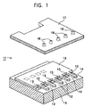
- FIG. 1 is an exploded perspective view showing a printer-head chip to which a liquid ejecting device of the present invention is applied;
- FIGS. 2A and 2B are a detailed plan view and side view showing the arrangement of heating resistors in the printer-head chip shown in FIG. 1 ;
- FIGS. 3A and 3B are graphs showing the relationship obtained in the case of each separate heating resistor 13 as in this embodiment between a difference in bubble producing time of ink and the ejection angle of ink droplets;
- FIG. 4 is a side sectional view showing the relationship between nozzles and printing paper
- FIG. 5 is a schematic circuit diagram showing a first example in which the difference between the bubble producing times of bisected heating resistors can be set;
- FIG. 6 is a schematic circuit diagram showing a second example in which the difference between the bubble producing times of bisected heating resistors can be set;
- FIG. 7 is a schematic circuit diagram showing a third embodiment in which the difference between the bubble producing times of bisected heating resistors can be set;
- FIG. 8 is a table showing results obtained in the circuit shown in FIG. 7 ;
- FIG. 9 is a schematic circuit diagram showing a fourth embodiment in which the difference between the bubble producing times of bisected heating resistors can be set.
- FIG. 10 is an illustration of the values of inputs B 1 and B 2 in FIG. 9 , and positions of delivered droplets;
- FIG. 11 is a plan view showing the specific shape of the circuit shown in FIG. 9 ;
- FIG. 12 is an illustration of a first modification to which the present invention is applied.
- FIG. 13 is an illustration of a second modification to which the present invention is applied.
- FIG. 14 is an illustration of a third modification to which the present invention is applied.
- FIG. 15 is an illustration of a fourth modification to which the present invention is applied.
- FIG. 16 is an illustration of a fifth modification to which the present invention is applied.
- FIG. 17 is an illustration of a sixth modification to which the present invention is applied.
- FIG. 18 consists of plan views showing a line head of the related art.
- FIGS. 19A and 19B are a sectional view and plan view showing the state of an image printed by the line head shown in FIG. 18 .
- FIG. 1 is an exploded perspective view showing a printer-head chip 11 to which a liquid ejecting device of the present invention is applied.
- a nozzle sheet 17 is bonded to a barrier layer 16 .
- the nozzle sheet 17 is shown, with it separated.
- the printer-head chip 11 is of a type using the above thermal method.
- a base member 14 includes a semiconductor substrate composed of silicon, etc., and heating resistors 13 (which correspond to bubble producing units or heating elements in the present invention, and which are used to produce bubbles in a liquid when being supplied with energy) formed on one surface of the semiconductor substrate 15 .
- the heating resistors 13 are electrically connected to an external circuit by a conductor portion (not shown) formed on the semiconductor substrate 15 .
- the barrier layer 16 is made of a photosensitive cyclized rubber resist or an exposure-curing dry-film resist, and is formed by stacking the resist on the entirety of the surface of the semiconductor substrate 15 on which the heating resistors 13 are formed, and using a photolithography process to remove unnecessary portions.
- the nozzle sheet 17 has therein a plurality of nozzles 18 having ejecting portions, and is formed by, for example, electroforming technology using nickel.
- the nozzle sheet 17 is bonded onto the barrier layer 16 so that the positions of the nozzles 18 can correspond to the positions of the heating resistors 13 , that is, the nozzles 18 can oppose the heating resistors 13 .
- Ink cells 12 are constituted so as to surround the heating resistors 13 by the substrate member 14 , the barrier layer 16 , and the nozzle sheet 17 .
- the substrate member 14 forms the bottom walls of the ink cells 12
- the barrier layer 16 forms the side walls of the ink cells 12
- the nozzle sheet 17 forms the top walls of the ink cells 12 .
- the ink cells 12 have aperture regions in the front right of FIG. 1 . The aperture regions are connected to ink-flow paths (not shown).
- the above printer-head chip 11 normally includes the heating resistors 13 in units of hundreds, and the ink cells 12 provided with the heating resistors 13 .
- each heating resistor 13 is uniquely selected, and the ink of the ink cell 12 corresponding to the heating resistor 13 can be ejected from the nozzle 18 opposing the ink cell 12 .
- the ink cell 12 is filled with ink supplied from an ink container (not shown) joined to the head 11 .
- the heating resistor 13 is rapidly heated.
- a gas-phase ink bubble is produced in a portion touching the heating resistor 13 , and the expansion of the ink bubble dislodges ink of some volume (the ink boils).
- ink of a volume equal to that of the dislodged ink in the portion touching the nozzle 18 is ejected as ink droplets from the nozzle 18 , and is delivered onto the printing paper.
- FIGS. 2A and 2B are respectively a detailed plan view and side sectional view showing the arrangement of the heating resistors 13 in the head 11 .
- the position of the nozzle 18 is indicated by the chain lines.
- one ink cell 12 includes two separate heating resistors 13 arranged in parallel.
- the ink cell 12 includes bisected heating resistors 13 .
- the direction in which the heating resistors 13 are arranged is a direction (the horizontal direction in FIGS. 2A and 2B ) in which the nozzles 18 are arranged.
- each separated heating resistor 13 has the same length and a half width.
- the resistance of the separated heating resistors 13 is double that of the original heating resistor 13 .
- the heating resistors 13 must be heated by supplying a certain amount of power to them. This is because energy generated at the boil is used to eject the ink. When the resistance is small, a current to pass must be increased. However, by increasing the resistance of the heating resistors 13 , the ink can be brought to a boil with a small current.
- the resistance can be increased.
- material selected for the heating resistors 13 and its strength (durability) there is a limitation in reducing the thickness of the heating resistors 13 . Accordingly, by separating the heating resistor 13 without reducing its thickness, the resistance of the heating resistors 13 is increased.
- one ink cell 12 includes the bisected heating resistors 13 , it is common that the time (bubble producing time) required for each heating resistor 13 to reach a temperature for boiling the ink is set to be equal.
- the bisected resistors 13 are physically not identical in shape. Due to an error in production, it is common that a dimension such as thickness changes. This causes a difference in bubble producing time. The creation of the difference in bubble producing time may cause a case in which the ink on one heating resistor 13 and the ink on the other heating resistor 13 do not boil.
- FIGS. 3A and 3B are graphs showing relationships obtained in the case of each separate heating resistor 13 as in this embodiment between a difference in bubble producing time of ink and the ejection angle of-ink droplet.
- the values shown in the graphs are computer-simulated results.
- the X-direction indicates a direction (the direction of the heating resistors 13 arranged in parallel) in which the nozzles 18 are arranged.
- the Y-direction indicates a direction perpendicular to the X-direction, which is a direction in which the printing paper is carried.
- the horizontal axis indicates difference in bubble producing time.
- a time difference of 0.04 microseconds corresponds to a variation of a 3-percent resistance difference
- a time difference of 0.08 seconds corresponds to a variation of approximately a 6-percent resistance difference.
- the bubble producing times of the heating resistors 13 are controlled.
- main operation controller means of ejecting an ink droplet from the nozzle 18 by supplying (uniform) energy to all of heating resistors 13 in one ink cell 12.
- main operation controller control for ejecting an ink droplet from the nozzle 18.
- the control is performed such that, as in this embodiment, when one ink cell 12 includes bisected heating resistors 13 , the simultaneous supply of equal amounts of energy (power) brings ink on the heating resistors 13 to a boil so that the time required for each heating resistor 13 to have a temperature for bringing the ink to a boil can be theoretically equal, in other words, an angle at which the ink is ejected can be perpendicular to a surface onto which the ink is delivered.
- the heating resistors 13 have a difference in bubble producing time.
- the use of only the main operation controller shifts the angle at which the ink is ejected from perpendicularity, so that the position to which the ink droplet is delivered is off from the correct position.
- the sub operation controller to control each heating resistor 13 to have an equal bubble producing time, the angle at which the ink is ejected can be set at perpendicularity.
- FIG. 4 is a side sectional view showing the relationship between the nozzles 18 and printing paper P.
- the distance H between the tips of the nozzles 18 and the printing paper P is approximately 1 to 2 millimeters in the case of an ordinary inkjet printer, it is here assumed that the distance H is maintained at a constant value, namely, approximately 2 millimeters.
- the reason the distance H must be maintained at approximately the constant value is because a change in the distance H changes the position to which the ink droplet is delivered.
- the position to which the ink droplet is delivered does not change, even if the distance H changes to some degree.
- the position to which the ink droplet is delivered changes in accordance with the change in the distance H.
- the interval (dot interval) between positions to which each ink droplet i is delivered is 25.40 ⁇ 1000/600 ⁇ 42.3 ( ⁇ m)
- the results shown in FIGS. 3A and 3B indicate that, to obtain a deflection angle of 0.43 degrees, a bubble producing time difference of approximately 0.09 ⁇ m is needed. This corresponds to a resistance difference of approximately 6.75%.
- the above distance H is preferably set to the range of 0.5 millimeters to 5 millimeters, and is more preferably set to approximately a constant value in the range of 1 millimeters to 3 millimeters.
- a value less than 0.5 millimeters as the distance H causes a small maximum movable amount of dot by deflective ejection of an ink droplet, so that a sufficient merit of the deflective ejection cannot be obtained.
- the precision of a position to which the ink droplet is delivered tends to decrease (because it is presumed that an effect of air resistance to the ink droplet increases while the ink droplet is being delivered).
- FIG. 5 is a schematic circuit diagram showing a first example in which the difference in bubble producing time of the heating resistors 13 can be set.
- the printer-head chip 11 is controlled so that energies of different amounts can simultaneously be supplied.
- the printer-head chip 11 is controlled so that energies of different amounts can simultaneously be supplied.
- it is ensured that, for stable ejection of ink droplets, sufficient amounts of energies are supplied to the two heating resistors 13 .
- stable ejection of ink droplets can be achieved while controlling the direction of ejection of the ink droplets.
- resistors Rh-A and Rh-B are the bisected heating resistors 13 , respectively.
- the circuit is formed so that a current can flow into or from a path (midpoint) for connecting the resistors Rh-A and Rh-B.
- a resistor Rx is used to deflect an ejected ink droplet.
- the resistor Rx and a switch Swb function to control the amount of heat by the resistors Rh-A and Rh-B.
- a power supply VH is used to allow a current to flow in the resistors Rh-A, Rh-B, and Rx.
- the ratio between the amount of heat generated in the resistor Rh-A and the amount of heat generated in the resistor Rh-B can be set freely. This can set a difference in bubble producing time between the resistors Rh-A and Rh-B. Thus, in response thereto, the direction of ejection of ink droplet can be changed.
- the switching of the switch Swb can change the currents flowing in the bisected heating resistors 13 .
- This can set a difference in bubble producing time between the resistors Rh-A and Rh-B, so that the direction of ejection of ink droplet can be changed.
- FIG. 6 is a schematic circuit diagram showing a second example in which the difference in bubble producing time between the bisected heating resistors 13 can be set.
- the circuit is controlled so that energies of equal or similar amounts can be supplied to the bisected heating resistors 13 at different times.
- the total amount of energy supplied to the heating resistors 13 when an ink droplet is ejected can be maintained to an amount at which the ink droplet can stably be ejected.
- stable ejection of the ink droplet can be performed, and by setting a difference in supply of energy to each heating resistor 13 , a feature of the present invention can be obtained in that the heating distributions of heating regions are changed while maintaining the total energy amount supplied to each heating resistor 13 .
- the resistors Rh-A and Rh-B are the bisected heating resistors 13 , respectively.
- a current can flow only in the resistor Rh-A.
- a switch Swb is turned on, a current can flow only in the resistor Rh-B.
- FIG. 7 is a schematic circuit diagram showing a third example in which the difference in bubble producing time between the bisected heating resistors 13 can be set.
- the difference in current between resistors Rh-A and Rh-B can be set to four types, whereby four directions in which an ink droplet can be ejected can be set.
- the resistors Rh-A and Rh-B are the bisected heating resistors 13 , respectively. In this example, their resistances are equal to each other.
- the circuit is formed so that a current can flow into or from a path (midpoint) for connecting the resistors Rh-A and Rh-B.
- Three resistors Rd are used to change a direction in which an ink droplet can be ejected.
- a transistor Q functions as a switch for the resistors Rh-A and Rh-B.
- the circuit includes an input portion C from which a binary control input signal (“1” only when a current may flow) is input.
- the circuit includes binary-input C-MOS/NAND gates L 1 and L 2 , and input portions B 1 and B 2 from which binary signals (“0” or “1”) for the NAND gates L 1 and L 2 are input.
- the NAND gates L 1 and L 2 are supplied with power from a power supply VH.
- the three resistors Rd, the transistor Q, the input portion C, and B 1 and B 2 , and the NAND gates L 1 and L 2 function to control the amounts of energies generated in the resistors Rh-A and Rh-B.
- the outputs of the NAND gates L 1 and L 2 are “0” and “1”, respectively.
- the current flowing in the resistor Rh-B is Rd/(Rh+Rd) when the current flowing in the resistor Rh-A is set to 1.
- both the outputs of the NAND gates L 1 and L 2 are 1s.
- currents flow in both C-MOS/NAND gates L 1 and L 2 .
- the current flowing in the resistor Rh-B is 2Rd/(3Rh+2Rd) when the current flowing in the Rh-A is set to 1.
- Rd ⁇ 20.7Rh 0.933 (approximately 6.7% decrease) can be obtained.
- the circuit is formed so that the current flowing from the resistor Rd to the NAND gate L 1 , and the current flowing from the resistor Rd to the NAND gate L 2 can flow into the ground of a power-circuit for driving the C-MOS/NAND gates L 1 and L 2 , which is not shown in FIG. 7 .
- FIG. 8 is a table showing the above results. As shown in FIG. 8 , in response to the inputs to the input portions B 1 and B 2 , the current flowing in the resistor Rh-B with respect to the current flowing in the resistor Rh-A can be changed.
- FIG. 9 is a schematic circuit diagram showing a fourth example in which the difference in bubble producing time between the bisected heating resistors 13 can be set.
- FIG. 9 also shows a modification of the circuit shown in FIG. 7 .
- transistors Q 2 and Q 3 of a type similar to that of a transistor Q 1 are provided and each transistor can be driven at a low voltage. This can lower driving voltages for gates L 1 and L 2 (AND gates in FIG. 9 ).
- Three transistors Rd, the transistors Q 1 , Q 2 , and Q 3 , input portions C, B 1 , and B 2 , and the AND gates L 1 and L 2 function to control the amounts of heat generated in the resistors Rh-A and Rh-B.
- resistors Rh-A and Rh-B in the circuit in FIG. 7 are set to have equal resistances
- the resistance of the resistor Rh-A is set to be smaller than that of the Rh-B.
- the resistor Rh-A generates the amount of heat less than that by the resistor Rh-B because the resistor Rh-A has a resistance less than that of the resistor Rh-B.
- setting is established so that an ejected ink droplet can be delivered to a position which is away half of the maximum movable amount of ink droplet from a reference position of delivery.
- FIG. 10 is an illustration of the values of inputs B 1 and B 2 and positions to which ink droplets are delivered. As shown in FIG. 10 , in this embodiment, the position to which the ink droplet is delivered can be changed to four. When 0s are input to the input portions B 1 and B 2 , the ink droplet can be delivered on the leftest in FIG. 10 (default).
- two positions namely, right and left positions to which an ink droplet can be delivered are set with respect to the correct position to which the ink droplet can be delivered.
- an arbitrary position can be set as the position to which the ink droplet is delivered.
- a maximum of 75% of one dot pitch can be moved with respect to a position to which an ink droplet is delivered which is used as a reference.
- an angle at which the ink droplet is ejected has a deflection angle of 0.86 degrees with respect to the vertical line.
- the inputs to the input portions B are represented by two bits, that is, “0” and “0”, “0” and “1”, “1” and “0”, and “1” and “1”.
- the position to which the ink droplet can be delivered is moved based on the 2-bit value, one dot pitch must be divided into three. In other words, four positions are formed as the position to which the ink droplet can be delivered.
- FIG. 11 is a plan view showing resistors Rh-A and Rh-B that satisfy the above relationship.
- the resistors Rh-A and Rh-B have equal widths (10 ⁇ m).
- the resistor Rh-A has a longitudinal length (the vertical length in FIG. 11 ) of 20 ⁇ m, and the resistor Rh-B has a longitudinal length of 21.4 ⁇ m.
- a portion ( 1 ) is connected to the power supply VH in FIG. 9
- a portion ( 2 ) is connected to the drain of the transistor Q 1 in FIG. 9
- a portion ( 3 ) is connected to the drains of both transistors Q 2 and Q 3 in FIG. 9 .
- FIG. 12 is an illustration of a first modification in which this embodiment is used, and shows positions by the head chip 11 in which ink droplets are delivered.
- the horizontal direction is the direction in which the nozzles 18 are arranged
- the vertical direction is the direction in which the printing paper is fed.
- the left side shows a state obtained before changing the positions to which the ink droplets are delivered
- the right side shows a state obtained after changing the positions to which the ink droplets are delivered.
- a column of the positions to which the ink droplets are delivered can be horizontally moved to four positions (( 1 ) to ( 4 ) in FIG. 12 ).
- the position by default to which each ink droplet is delivered is set in position ( 3 ) among positions ( 1 ) to ( 4 ).
- the position which each ink droplet is delivered can be moved by only 25% of one dot pitch.
- the ink droplets are delivered by the above-described main operation controller.
- the third column from the left of the positions to which the ink droplets are delivered is off to the right. Accordingly, a white stripe is formed between the second column and the third column and printing quality deteriorates.
- the white stripe between the second column and the third column can be reduced.
- the third column by moving only the third column from position ( 3 ) to ( 2 ), that is, to the left by 25% of one dot pitch, the third column can be positioned near the center between the second column and the fourth column.
- the right side in FIG. 12 shows a state in which, by shifting the third column from position ( 3 ) to ( 2 ), the third column is moved by 25%. In this manner, the ink droplets in the third column can be brought close to the center between the second column and the fourth column. This can make the white stripe unclear.
- the first, second, and fourth columns from the left are formed by delivering ink droplets from the main operation controller.
- the third column from the left is formed such that, by using the sub operation controller to eject ink droplets having flying characteristics different from those of ink droplets by the main operation controller, a direction in which the ink droplets are delivered is changed, whereby positions to which the ink droplets are delivered are changed from the positions (( 3 ) in FIG. 12 ) by the main operation controller to the more left side (( 2 ) in FIG. 12 ).
- the supply of energy to each heating resistor 13 in each ink cell 12 may be controlled in accordance with the stored data.
- each nozzle 18 by setting and storing data on a difference between the time required for the ink droplet on one heating resistor 13 to boil and the time required for the ink droplet on the other heating resistor 13 to boil, the supply of energy to each heating resistor 13 in each ink cell 12 may be controlled in accordance with the stored data.
- FIGS. 19A and 19B are used for description.
- a direction in which ink droplets are delivered from all the nozzles 18 may be changed to the right by a predetermined amount
- a direction in which ink droplets from all the nozzles 18 are delivered may be changed to the left by a predetermined amount.
- a direction in which ink droplets from some of the nozzles 18 are delivered may be changed.
- the positions of the nozzles 18 of each printer-head chip 11 are fixed beforehand.
- positions to which ink droplets are delivered are determined beforehand.
- the interval between the nozzles 18 is 42.3 micrometers.
- an image having a resolution of 1200 dpi can be printed.
- the resolution can substantially be increased, thus increasing printing quality.
- FIG. 13 is an illustration of a second modification in which this embodiment is used.
- the second modification is an example of a dot arrangement based on dot interleaving in which the dot pitch in each line is set to be constant, and in the next line its dots are arranged in the intermediate positions of the first line.
- each position to which an ink droplet is delivered can be changed to four points ( 1 ) to ( 4 ), and point ( 4 ) is set by default.
- N+1 line by changing, from positions ( 4 ) to ( 2 ), all positions to which ink droplets are delivered are changed, the ink droplets are delivered to positions moved to the left by 50% of one dot pitch.
- N+2 line ink droplets are delivered to positions identical to those for the N line.
- N+1, N+3, N+5, . . . lines ink droplets are ejected and deflected by the sub operation controller and are delivered to position ( 2 ).
- ink droplets are delivered based on ( 4 ), and in N+1, N+3, N+5, . . . lines (odd-numbered lines), ink droplets are delivered based on position ( 2 ).
- the positions may be moved in each set of several lines. Also, the amount of movement from a default dot position is not particularly limited.
- the supply of energy to the heating resistor 13 may be controlled in accordance with the stored data.
- FIG. 14 is an illustration of a third modification in which this embodiment is used and in which a technique similar to dithering is used.
- Dithering means that, in order to weaken unnaturalness generated when the spatial resolution of pixels in a sampled image is insufficient, when the original image is quantized, the quantization is performed, with slight noise and high-frequency signal superimposed in an input signal beforehand.
- FIG. 14 differs from dithering in a narrow sense, but has an effect similar to dithering.
- default positions to which ink droplets are delivered are set in ( 4 ).
- dot size is sufficiently small.
- binary-bit values are output by a pseudorandom function generator and are added to input signals to the input portions B 1 and B 2 . This can appropriately change a position to which an ink droplet is delivered.
- the first and fourth ink droplets from the left are delivered to default position ( 4 ) by the main operation controller, and each of the second and third ink droplets from the left is delivered to position ( 3 ) which is moved to the left by 25% of one dot from the default position.
- the above technique can also increase printing quality.
- FIG. 15 consists of illustrations of a fourth modification in which this embodiment is used and shows a dot averaging process.
- FIG. 15 the upper illustration shows a state in which ink droplets are ejected without being deflected.
- the ink droplets are delivered by the main operation controller.
- the fourth and eighth columns of dots indicate that the dots are smaller than the other columns of dots (whose insides are indicated by hatched lines).
- the sixth column of dots indicate that the dots are much smaller than the fourth and eighth columns of dots.
- the dot averaging process is performed by using the sub operation controller.
- the nozzle 18 corresponding to the sixth column is controlled to deliver ink droplets not only in the sixth column but also in another column (the fifth column or the seventh column in this example), and is controlled so as not to deliver ink droplets in consecutive rows in one column. This also applies to ink droplets ejected from the nozzles 18 corresponding to the fourth and eighth columns.
- ink droplets ejected from the nozzles 18 corresponding to the fourth, sixth, and eighth columns are prevented from being delivered to consecutive rows in one column. This can prevent density nonuniformity from looking clearly and can increase picture quality.
- FIG. 16 illustrates a fifth modification in which this embodiment is used, and the formation of high resolution.
- the printer-head chip 11 has a resolution of 600 dpi (the interval between the nozzles 18 is 42.3 micrometers).
- the case ( 1 ) shows that dots are formed by delivering ink droplets from the main operation controller.
- the dot pitch obtained when using only the main operation controller is equal to the interval between the nozzles 18 in the printer-head chip 11 , that is, 42.3 micrometers.
- the cases ( 2 ) to ( 4 ) show that, by using the sub operation controller to interpolate new dots in dots formed by the main operation controller, the printing resolution is increased.
- ink droplets are delivered by the main operation controller similarly to the case ( 1 ), and by using the sub operation controller to form new dots in dot formed by the main operation controller, the dot density is doubled.
- a method similar to that shown in FIG. 13 is used.
- the feeding pitch of printing paper is set to be half that in the case ( 1 ).
- the portion ( 3 ) shows a state in which the dot density is quadrupled.
- the ink droplets are controlled to be delivered to the feeding direction of printing paper at a density double that used in the case ( 1 ) (i.e., the feeding pitch of printing paper is set to be half that used in the case ( 1 )).
- the ink droplets may be delivered at the density double that used in the case ( 2 ).
- the portion ( 4 ) shows a state in which the dot density is octupled.
- the dots are formed in the feeding direction of the printing paper at a density double that used in the case ( 1 ). This point is similar to dot formation by the main operation controller in the case ( 1 ).
- ejected ink droplets are deflected and delivered so that three new columns of dots can be positioned between the dots formed by the main operation controller.
- the three columns of dots formed by the sub operation controller which are positioned between two columns of dots formed by the main operation controller, are obtained such that, from the nozzle 18 corresponding to the left column of dots between two columns of dots formed by the main operation controller, ink droplets are ejected and deflected in two different right directions to form two columns among the three columns, and from the nozzle 18 corresponding to the right column of dots between the two columns of dots formed by the main operation controller, ink droplets are ejected and deflected to the left to form the other one column of dots among the three columns of dots.
- the printer-head chip 11 has a physical resolution of 600 dpi
- printing at 600 dpi can be performed only by the main operation controller, as in the case ( 1 ).
- the use of the sub operation controller enables printing at the double density (1200 dpi) as in the case ( 2 ), printing at the fourfold density (2400 dpi) as in the case ( 3 ), and printing at the eightfold density (4800 dpi) as in the case ( 4 ).
- the above increase in resolution is particularly effective in a case in which dot diameter is small due to the interval between two nozzles 18 .
- FIG. 17 illustrates a sixth modification in which this embodiment is used and which has a wobbled state.
- example (1) shows dot formation only by the main operation controller, in which four columns of dots are arranged in parallel with the feeding direction of printing paper at intervals of the nozzles 18 .
- example (2) shows that columns of dots are obliquely formed by the sub operation controller.
- dots are formed by the main operation controller.
- the second row by controlling the nozzles 18 to eject and deflect ink droplets to the right, dots are formed at the lower right portions to the first column of dots.
- dots are formed at the lower right portions to the lower right portions to the second row of dots.
- dots are formed at the lower right portions to the lower right portions to the second row of dots. In this manner, by gradually increasing the amount of deflection as the row number increases, oblique columns of dots can be formed as shown in the example (2). This dot formation prevents nonuniformity and stripes from looking clear.
- example (3) shows that columns of dots are obliquely formed, similarly to the example (2).
- the main operation controller is used to form dots.
- the second to fourth rows similarly to the example (2), by controlling the nozzles 18 to eject and deflect ink droplets in the right in FIG. 17 , dots are formed at the lower right portions to the upper column of dots.
- dots are formed at the lower left portions to the upper column of dots.
- Dot arrangement in the eighth and subsequent columns is similar to that in the second and subsequent columns. As described above, by forming the columns of dots in a triangular form, stripes and nonuniformity can be prevented from looking clearly.
- Printing methods such as the examples (2) and (3) in FIG. 16 are realized in a serial printer by reciprocally moving its head a great number of times, that is, overwriting. Conversely, in a line printer whose head does not move, it has been impossible to perform such wobbling. However, in the present invention, the printing methods are realized by using the sub operation controller.
- a heating resistor 13 composed of a single base, if it is one in which the distribution of energy in a bubble producing region (surface region) can be set to have a difference, for example, one in which the entire bubble producing region does not uniformly generate heat and in which a portion of the region and another portion can be set to have a difference in generating heat, it does not always need to be separated.
Abstract
Description
ΔL=H×tan θ
with the distance (normally 1 to 2 millimeters in the case of the inkjet method) between the ejection surface and the surface (a surface on which the ink droplet is delivered) of printing paper set to H (H is constant).
25.40×1000/600≈42.3 (μm)
tan 2θ=30/2000≈0.015
Thus, θ≈0.43 (deg)
(Rh×Rx)/(Rh×(Rh+Rx))=Rx/(Rh+R)=1−0.0675=0.9325
Hence, Rx≈13.8×Rh
Rx=2Rd/3
Resistance of Rh-B=Resistance of Rh-A×1.0675
21.4/40=approximately 1.0675
- (1) In the above-described embodiment, by changing currents to bisected
heating resistors 13, the times (bubble producing time) required for ink droplets on theheating resistors 13 to boil can differ from each other. In addition, this can be combined with a technique in which the times in which currents are supplied to the bisectedheating resistors 13 are controlled to differ. - (2) In the above-described embodiment, a case in which two
heating resistors 13 are arranged in parallel in oneink cell 12 has been described. The reason of bisection is that the durability of the bisectedheating resistors 13 is sufficiently proven and the circuit configuration can be simplified. However, the arrangement of theheating resistors 13 is not limited to the above case, but an arrangement in which at least threeheating resistors 13 are arranged in parallel in oneink cell 12 may be used. - (3) In the above-described embodiment, the printer-
head chip 11 and the line head for use in the printer are exemplified. However, the present invention is not limited to the printer, but can be applied to a device for ejecting a DNA-contained solution for detecting a biological sample. - (4) In the above-described embodiment, the
heating resistors 13 are exemplified. However, heating elements composed of a substance other than a resistor, or other types of energy generators and bubble producers may be used. - (5) In the above-described embodiment, the bisected
heating resistors 13 are exemplified. However, theseplural heating resistors 13 do not always need to be physically separated.
- (6) For means of bubble production, the
heating resistors 13 or the like are used to produce bubbles in the ink in theink cells 12 by supplying thermal energy. The means of bubble production is not limited to this technique. For example, the means of bubble production may be such an energy supplying method that the ink (liquid) in theink cells 12 generates heat by itself.
Claims (3)
Priority Applications (1)
| Application Number | Priority Date | Filing Date | Title |
|---|---|---|---|
| US11/109,000 US7213905B2 (en) | 2002-04-16 | 2005-04-18 | Liquid ejecting device |
Applications Claiming Priority (7)
| Application Number | Priority Date | Filing Date | Title |
|---|---|---|---|
| JPJP2002-112947 | 2002-04-16 | ||
| JP2002112947 | 2002-04-16 | ||
| JP2002320861A JP2004001364A (en) | 2002-04-16 | 2002-11-05 | Liquid discharge apparatus and liquid discharge method |
| JPJP2002-320861 | 2002-11-05 | ||
| US10/354,762 US6749286B2 (en) | 2002-04-16 | 2003-01-30 | Liquid ejecting device and liquid ejecting method |
| US10/807,440 US6880917B2 (en) | 2002-04-16 | 2004-03-22 | Liquid ejecting device and liquid ejecting method |
| US11/109,000 US7213905B2 (en) | 2002-04-16 | 2005-04-18 | Liquid ejecting device |
Related Parent Applications (1)
| Application Number | Title | Priority Date | Filing Date |
|---|---|---|---|
| US10/807,440 Continuation US6880917B2 (en) | 2002-04-16 | 2004-03-22 | Liquid ejecting device and liquid ejecting method |
Publications (2)
| Publication Number | Publication Date |
|---|---|
| US20050185024A1 US20050185024A1 (en) | 2005-08-25 |
| US7213905B2 true US7213905B2 (en) | 2007-05-08 |
Family
ID=28677643
Family Applications (3)
| Application Number | Title | Priority Date | Filing Date |
|---|---|---|---|
| US10/354,762 Expired - Lifetime US6749286B2 (en) | 2002-04-16 | 2003-01-30 | Liquid ejecting device and liquid ejecting method |
| US10/807,440 Expired - Lifetime US6880917B2 (en) | 2002-04-16 | 2004-03-22 | Liquid ejecting device and liquid ejecting method |
| US11/109,000 Expired - Fee Related US7213905B2 (en) | 2002-04-16 | 2005-04-18 | Liquid ejecting device |
Family Applications Before (2)
| Application Number | Title | Priority Date | Filing Date |
|---|---|---|---|
| US10/354,762 Expired - Lifetime US6749286B2 (en) | 2002-04-16 | 2003-01-30 | Liquid ejecting device and liquid ejecting method |
| US10/807,440 Expired - Lifetime US6880917B2 (en) | 2002-04-16 | 2004-03-22 | Liquid ejecting device and liquid ejecting method |
Country Status (6)
| Country | Link |
|---|---|
| US (3) | US6749286B2 (en) |
| EP (1) | EP1354704B1 (en) |
| JP (1) | JP2004001364A (en) |
| KR (1) | KR100975169B1 (en) |
| CN (1) | CN1328053C (en) |
| SG (1) | SG110040A1 (en) |
Families Citing this family (37)
| Publication number | Priority date | Publication date | Assignee | Title |
|---|---|---|---|---|
| JP3617644B2 (en) | 2002-03-26 | 2005-02-09 | ソニー株式会社 | Liquid ejection device |
| JP4023331B2 (en) * | 2002-06-03 | 2007-12-19 | ソニー株式会社 | Liquid ejection apparatus and liquid ejection method |
| US7845749B2 (en) | 2002-11-13 | 2010-12-07 | Sony Corporation | Liquid-ejecting method and liquid-ejecting apparatus |
| US7222927B2 (en) | 2002-12-12 | 2007-05-29 | Sony Corporation | Liquid discharge device and liquid discharge method |
| JP4114202B2 (en) * | 2003-02-28 | 2008-07-09 | ソニー株式会社 | Liquid ejection head, liquid ejection apparatus, and liquid ejection head driving method |
| US7254523B2 (en) * | 2003-03-14 | 2007-08-07 | Seiko Epson Corporation | Selectively reduced bi-cubic interpolation for ink-jet simulations on quadrilateral grids |
| US7117138B2 (en) * | 2003-03-14 | 2006-10-03 | Seiko Epson Corporation | Coupled quadrilateral grid level set scheme for piezoelectric ink-jet simulation |
| JP2005001346A (en) * | 2003-06-16 | 2005-01-06 | Sony Corp | Liquid injection device and liquid injection method |
| JP4148074B2 (en) * | 2003-09-05 | 2008-09-10 | ソニー株式会社 | Discharge control device, liquid discharge device, liquid discharge method, recording medium, and program |
| JP4632648B2 (en) | 2003-10-02 | 2011-02-16 | ソニー株式会社 | Liquid ejection apparatus and liquid ejection method |
| JP4144518B2 (en) | 2003-10-10 | 2008-09-03 | ソニー株式会社 | Liquid ejection device |
| JP2005238565A (en) * | 2004-02-25 | 2005-09-08 | Sony Corp | Liquid discharging apparatus, and driving method of liquid discharging apparatus |
| JP4643162B2 (en) | 2004-03-25 | 2011-03-02 | ブラザー工業株式会社 | Inkjet head control apparatus, inkjet head control method, and inkjet recording apparatus |
| US7364277B2 (en) | 2004-04-14 | 2008-04-29 | Eastman Kodak Company | Apparatus and method of controlling droplet trajectory |
| US20050243117A1 (en) * | 2004-04-28 | 2005-11-03 | Jiun-Der Yu | Divergence filters on quadrilateral grids for ink-jet simulations |
| JP3897120B2 (en) * | 2004-06-17 | 2007-03-22 | ソニー株式会社 | Liquid ejecting apparatus and method of manufacturing liquid ejecting apparatus |
| JP2006192622A (en) | 2005-01-12 | 2006-07-27 | Sony Corp | Liquid-delivering head, liquid-delivering apparatus, and method for manufacturing liquid-delivering head |
| US8787706B2 (en) | 2005-03-18 | 2014-07-22 | The Invention Science Fund I, Llc | Acquisition of a user expression and an environment of the expression |
| US8290313B2 (en) | 2005-03-18 | 2012-10-16 | The Invention Science Fund I, Llc | Electronic acquisition of a hand formed expression and a context of the expression |
| US8102383B2 (en) | 2005-03-18 | 2012-01-24 | The Invention Science Fund I, Llc | Performing an action with respect to a hand-formed expression |
| US8340476B2 (en) | 2005-03-18 | 2012-12-25 | The Invention Science Fund I, Llc | Electronic acquisition of a hand formed expression and a context of the expression |
| US7809215B2 (en) * | 2006-10-11 | 2010-10-05 | The Invention Science Fund I, Llc | Contextual information encoded in a formed expression |
| US8823636B2 (en) | 2005-03-18 | 2014-09-02 | The Invention Science Fund I, Llc | Including environmental information in a manual expression |
| US7672512B2 (en) | 2005-03-18 | 2010-03-02 | Searete Llc | Forms for completion with an electronic writing device |
| US7873243B2 (en) | 2005-03-18 | 2011-01-18 | The Invention Science Fund I, Llc | Decoding digital information included in a hand-formed expression |
| US8229252B2 (en) | 2005-03-18 | 2012-07-24 | The Invention Science Fund I, Llc | Electronic association of a user expression and a context of the expression |
| US8232979B2 (en) | 2005-05-25 | 2012-07-31 | The Invention Science Fund I, Llc | Performing an action with respect to hand-formed expression |
| WO2007088948A1 (en) * | 2006-02-03 | 2007-08-09 | Murata Manufacturing Co., Ltd. | Electronic component and method for manufacturing same |
| US7536285B2 (en) * | 2006-08-14 | 2009-05-19 | Seiko Epson Corporation | Odd times refined quadrilateral mesh for level set |
| TWI322085B (en) * | 2007-03-07 | 2010-03-21 | Nat Univ Tsing Hua | Micro-droplet injector apparatus having nozzle arrays without individual chambers and ejection method of droplets thereof |
| JP4582225B2 (en) * | 2008-08-15 | 2010-11-17 | ソニー株式会社 | Liquid ejection apparatus and liquid ejection method |
| CN101817256B (en) * | 2010-04-30 | 2011-08-10 | 华中科技大学 | Jet-printing head based on double-carbon nanotube microbubble generator and preparation method thereof |
| JP2014091318A (en) * | 2012-11-07 | 2014-05-19 | Seiko Epson Corp | Inkjet recording method and recorded object |
| US9861720B2 (en) * | 2014-06-20 | 2018-01-09 | Stmicroelectronics, Inc. | Microfluidic delivery system and method |
| US9968700B2 (en) * | 2014-06-20 | 2018-05-15 | Stmicroelectronics, Inc. | Microfluidic delivery system and method |
| JP6883193B2 (en) * | 2016-10-19 | 2021-06-09 | 富士フイルムビジネスイノベーション株式会社 | Droplet ejection device, image forming device, and program |
| JP2018065287A (en) * | 2016-10-19 | 2018-04-26 | 富士ゼロックス株式会社 | Droplet discharge device, image formation apparatus and program |
Citations (12)
| Publication number | Priority date | Publication date | Assignee | Title |
|---|---|---|---|---|
| US4251824A (en) * | 1978-11-14 | 1981-02-17 | Canon Kabushiki Kaisha | Liquid jet recording method with variable thermal viscosity modulation |
| US5172139A (en) | 1989-05-09 | 1992-12-15 | Ricoh Company, Ltd. | Liquid jet head for gradation recording |
| JPH06210856A (en) | 1993-01-14 | 1994-08-02 | Sony Corp | On-demand type ink jet printer apparatus |
| JPH0848034A (en) | 1994-08-08 | 1996-02-20 | Nec Corp | Ink jet printing head and its driving method |
| EP0816085A2 (en) | 1996-06-28 | 1998-01-07 | Canon Kabushiki Kaisha | A method for adjusting an amount of discharge between a plurality of liquid discharge nozzle units, an ink jet driving method using such method of adjustment, and an ink jet apparatus |
| US5726697A (en) | 1990-06-15 | 1998-03-10 | Canon Kabushiki Kaisha | Ink jet recording apparatus having an optimally-dimensioned ink jet head structure |
| EP0997278A2 (en) | 1998-10-27 | 2000-05-03 | Canon Kabushiki Kaisha | Ink-jet printing apparatus, ejection recovery method for ink-jet printing apparatus, and fabrication method of ink-jet printing head |
| US6074046A (en) | 1998-03-06 | 2000-06-13 | Eastman Kodak Company | Printer apparatus capable of varying direction of an ink droplet to be ejected therefrom and method therefor |
| US6164748A (en) | 1997-07-31 | 2000-12-26 | Canon Kabushiki Kaisha | Liquid discharge method and liquid jet apparatus |
| WO2001047713A1 (en) | 1999-12-28 | 2001-07-05 | Hitachi Koki Co., Ltd. | Line-scanning type ink jet recorder |
| US6474789B1 (en) | 1991-08-02 | 2002-11-05 | Canon Kabushiki Kaisha | Recording apparatus, recording head and substrate therefor |
| JP2003211666A (en) | 2002-01-28 | 2003-07-29 | Sharp Corp | Ink jet head, ink jet recorder, and combined machine |
Family Cites Families (2)
| Publication number | Priority date | Publication date | Assignee | Title |
|---|---|---|---|---|
| JP3787448B2 (en) * | 1998-12-21 | 2006-06-21 | キヤノン株式会社 | Inkjet recording method and inkjet recording apparatus |
| JP2001105584A (en) * | 1999-10-14 | 2001-04-17 | Canon Inc | Ink jet recorder |
-
2002
- 2002-11-05 JP JP2002320861A patent/JP2004001364A/en active Pending
-
2003
- 2003-01-29 EP EP03002058.0A patent/EP1354704B1/en not_active Expired - Fee Related
- 2003-01-30 US US10/354,762 patent/US6749286B2/en not_active Expired - Lifetime
- 2003-01-30 KR KR1020030006152A patent/KR100975169B1/en not_active IP Right Cessation
- 2003-01-31 CN CNB031286631A patent/CN1328053C/en not_active Expired - Fee Related
- 2003-04-04 SG SG200301961A patent/SG110040A1/en unknown
-
2004
- 2004-03-22 US US10/807,440 patent/US6880917B2/en not_active Expired - Lifetime
-
2005
- 2005-04-18 US US11/109,000 patent/US7213905B2/en not_active Expired - Fee Related
Patent Citations (12)
| Publication number | Priority date | Publication date | Assignee | Title |
|---|---|---|---|---|
| US4251824A (en) * | 1978-11-14 | 1981-02-17 | Canon Kabushiki Kaisha | Liquid jet recording method with variable thermal viscosity modulation |
| US5172139A (en) | 1989-05-09 | 1992-12-15 | Ricoh Company, Ltd. | Liquid jet head for gradation recording |
| US5726697A (en) | 1990-06-15 | 1998-03-10 | Canon Kabushiki Kaisha | Ink jet recording apparatus having an optimally-dimensioned ink jet head structure |
| US6474789B1 (en) | 1991-08-02 | 2002-11-05 | Canon Kabushiki Kaisha | Recording apparatus, recording head and substrate therefor |
| JPH06210856A (en) | 1993-01-14 | 1994-08-02 | Sony Corp | On-demand type ink jet printer apparatus |
| JPH0848034A (en) | 1994-08-08 | 1996-02-20 | Nec Corp | Ink jet printing head and its driving method |
| EP0816085A2 (en) | 1996-06-28 | 1998-01-07 | Canon Kabushiki Kaisha | A method for adjusting an amount of discharge between a plurality of liquid discharge nozzle units, an ink jet driving method using such method of adjustment, and an ink jet apparatus |
| US6164748A (en) | 1997-07-31 | 2000-12-26 | Canon Kabushiki Kaisha | Liquid discharge method and liquid jet apparatus |
| US6074046A (en) | 1998-03-06 | 2000-06-13 | Eastman Kodak Company | Printer apparatus capable of varying direction of an ink droplet to be ejected therefrom and method therefor |
| EP0997278A2 (en) | 1998-10-27 | 2000-05-03 | Canon Kabushiki Kaisha | Ink-jet printing apparatus, ejection recovery method for ink-jet printing apparatus, and fabrication method of ink-jet printing head |
| WO2001047713A1 (en) | 1999-12-28 | 2001-07-05 | Hitachi Koki Co., Ltd. | Line-scanning type ink jet recorder |
| JP2003211666A (en) | 2002-01-28 | 2003-07-29 | Sharp Corp | Ink jet head, ink jet recorder, and combined machine |
Also Published As
| Publication number | Publication date |
|---|---|
| US20030193544A1 (en) | 2003-10-16 |
| US6749286B2 (en) | 2004-06-15 |
| EP1354704A1 (en) | 2003-10-22 |
| US20050185024A1 (en) | 2005-08-25 |
| JP2004001364A (en) | 2004-01-08 |
| SG110040A1 (en) | 2005-04-28 |
| CN1328053C (en) | 2007-07-25 |
| CN1473706A (en) | 2004-02-11 |
| EP1354704B1 (en) | 2013-10-09 |
| KR100975169B1 (en) | 2010-08-10 |
| US20040246303A1 (en) | 2004-12-09 |
| US6880917B2 (en) | 2005-04-19 |
| KR20030082893A (en) | 2003-10-23 |
Similar Documents
| Publication | Publication Date | Title |
|---|---|---|
| US7213905B2 (en) | Liquid ejecting device | |
| US7198344B2 (en) | Liquid ejecting device and liquid ejecting method | |
| CN101254694B (en) | Liquid discharge apparatus and method for discharging liquid | |
| EP1705013B1 (en) | Liquid ejecting head and liquid ejecting apparatus | |
| JP4055149B2 (en) | Liquid ejection apparatus and liquid ejection method | |
| US7823998B2 (en) | Liquid ejection apparatus and liquid ejection method | |
| KR101034322B1 (en) | Liquid ejecting method and liquid ejecting apparatus | |
| JP3812667B2 (en) | Liquid ejection apparatus and liquid ejection method | |
| JP3849801B2 (en) | Liquid ejection apparatus and liquid ejection method | |
| JP3849800B2 (en) | Liquid ejection apparatus and liquid ejection method | |
| JP3682693B2 (en) | Liquid ejection apparatus and liquid ejection method | |
| JP2006088711A (en) | Liquid ejecting device and liquid ejecting method | |
| JP2004160848A (en) | Liquid ejector |
Legal Events
| Date | Code | Title | Description |
|---|---|---|---|
| STCF | Information on status: patent grant |
Free format text: PATENTED CASE |
|
| FEPP | Fee payment procedure |
Free format text: PAYOR NUMBER ASSIGNED (ORIGINAL EVENT CODE: ASPN); ENTITY STATUS OF PATENT OWNER: LARGE ENTITY Free format text: PAYER NUMBER DE-ASSIGNED (ORIGINAL EVENT CODE: RMPN); ENTITY STATUS OF PATENT OWNER: LARGE ENTITY |
|
| FPAY | Fee payment |
Year of fee payment: 4 |
|
| FPAY | Fee payment |
Year of fee payment: 8 |
|
| FEPP | Fee payment procedure |
Free format text: MAINTENANCE FEE REMINDER MAILED (ORIGINAL EVENT CODE: REM.); ENTITY STATUS OF PATENT OWNER: LARGE ENTITY |
|
| LAPS | Lapse for failure to pay maintenance fees |
Free format text: PATENT EXPIRED FOR FAILURE TO PAY MAINTENANCE FEES (ORIGINAL EVENT CODE: EXP.); ENTITY STATUS OF PATENT OWNER: LARGE ENTITY |
|
| STCH | Information on status: patent discontinuation |
Free format text: PATENT EXPIRED DUE TO NONPAYMENT OF MAINTENANCE FEES UNDER 37 CFR 1.362 |
|
| FP | Lapsed due to failure to pay maintenance fee |
Effective date: 20190508 |