US7190135B2 - Method of inverter linearization in electric machines through secondary modulation - Google Patents
Method of inverter linearization in electric machines through secondary modulation Download PDFInfo
- Publication number
- US7190135B2 US7190135B2 US10/458,091 US45809103A US7190135B2 US 7190135 B2 US7190135 B2 US 7190135B2 US 45809103 A US45809103 A US 45809103A US 7190135 B2 US7190135 B2 US 7190135B2
- Authority
- US
- United States
- Prior art keywords
- value
- voltage command
- desired voltage
- motor
- time
- Prior art date
- Legal status (The legal status is an assumption and is not a legal conclusion. Google has not performed a legal analysis and makes no representation as to the accuracy of the status listed.)
- Expired - Fee Related, expires
Links
Images


Classifications
-
- B—PERFORMING OPERATIONS; TRANSPORTING
- B62—LAND VEHICLES FOR TRAVELLING OTHERWISE THAN ON RAILS
- B62D—MOTOR VEHICLES; TRAILERS
- B62D5/00—Power-assisted or power-driven steering
- B62D5/04—Power-assisted or power-driven steering electrical, e.g. using an electric servo-motor connected to, or forming part of, the steering gear
- B62D5/0457—Power-assisted or power-driven steering electrical, e.g. using an electric servo-motor connected to, or forming part of, the steering gear characterised by control features of the drive means as such
- B62D5/046—Controlling the motor
- B62D5/0463—Controlling the motor calculating assisting torque from the motor based on driver input
-
- H—ELECTRICITY
- H02—GENERATION; CONVERSION OR DISTRIBUTION OF ELECTRIC POWER
- H02M—APPARATUS FOR CONVERSION BETWEEN AC AND AC, BETWEEN AC AND DC, OR BETWEEN DC AND DC, AND FOR USE WITH MAINS OR SIMILAR POWER SUPPLY SYSTEMS; CONVERSION OF DC OR AC INPUT POWER INTO SURGE OUTPUT POWER; CONTROL OR REGULATION THEREOF
- H02M7/00—Conversion of ac power input into dc power output; Conversion of dc power input into ac power output
- H02M7/42—Conversion of dc power input into ac power output without possibility of reversal
- H02M7/44—Conversion of dc power input into ac power output without possibility of reversal by static converters
- H02M7/48—Conversion of dc power input into ac power output without possibility of reversal by static converters using discharge tubes with control electrode or semiconductor devices with control electrode
- H02M7/53—Conversion of dc power input into ac power output without possibility of reversal by static converters using discharge tubes with control electrode or semiconductor devices with control electrode using devices of a triode or transistor type requiring continuous application of a control signal
- H02M7/537—Conversion of dc power input into ac power output without possibility of reversal by static converters using discharge tubes with control electrode or semiconductor devices with control electrode using devices of a triode or transistor type requiring continuous application of a control signal using semiconductor devices only, e.g. single switched pulse inverters
- H02M7/5387—Conversion of dc power input into ac power output without possibility of reversal by static converters using discharge tubes with control electrode or semiconductor devices with control electrode using devices of a triode or transistor type requiring continuous application of a control signal using semiconductor devices only, e.g. single switched pulse inverters in a bridge configuration
- H02M7/53871—Conversion of dc power input into ac power output without possibility of reversal by static converters using discharge tubes with control electrode or semiconductor devices with control electrode using devices of a triode or transistor type requiring continuous application of a control signal using semiconductor devices only, e.g. single switched pulse inverters in a bridge configuration with automatic control of output voltage or current
- H02M7/53875—Conversion of dc power input into ac power output without possibility of reversal by static converters using discharge tubes with control electrode or semiconductor devices with control electrode using devices of a triode or transistor type requiring continuous application of a control signal using semiconductor devices only, e.g. single switched pulse inverters in a bridge configuration with automatic control of output voltage or current with analogue control of three-phase output
-
- H—ELECTRICITY
- H02—GENERATION; CONVERSION OR DISTRIBUTION OF ELECTRIC POWER
- H02M—APPARATUS FOR CONVERSION BETWEEN AC AND AC, BETWEEN AC AND DC, OR BETWEEN DC AND DC, AND FOR USE WITH MAINS OR SIMILAR POWER SUPPLY SYSTEMS; CONVERSION OF DC OR AC INPUT POWER INTO SURGE OUTPUT POWER; CONTROL OR REGULATION THEREOF
- H02M1/00—Details of apparatus for conversion
- H02M1/0003—Details of control, feedback or regulation circuits
- H02M1/0025—Arrangements for modifying reference values, feedback values or error values in the control loop of a converter
Definitions
- the present disclosure relates generally to automobile steering systems and, more particularly, to a method of inverter linearization in electric machines such as electric power steering (EPS) motors through secondary modulation of a motor voltage command thereto.
- EPS electric power steering
- Electric power steering has been recently implemented in motor vehicles to improve fuel economy and has even started to replace hydraulic power steering in certain vehicles.
- One way to accomplish improved fuel economy is through the reduction or elimination of losses inherent in traditional steering systems.
- electric power steering requires power only on demand.
- an electronic controller is also configured to require significantly less power under a small or no steering input condition. This dramatic decrease from conventional steering assist is the basis of the power and fuel savings.
- a polyphase permanent magnet (PM) brushless motor is typically used in EPS systems as the actuator for providing a mechanical assist to the vehicle's steering mechanism.
- EPS polyphase permanent magnet
- Such a motor is generally excited with a sinusoidal field to provide lower torque ripple, noise, and vibration as compared to those motors excited with a trapezoidal field.
- EMF sinusoidal back electromotive force
- the torque output of the motor will be a constant, and zero torque ripple will be achieved.
- Various methods of torque control can influence the magnitude and characteristics of this torque ripple.
- a full bridge power inverter is employed to apply a pulse width modulated (PWM) voltage across the motor phases.
- PWM pulse width modulated
- these inverters suffer, however, from several linearity issues. More specifically, an inverter used in conjunction with a sinusoidal motor with phase grounding can generate considerable torque ripple at relatively low voltage commands.
- the torque output versus voltage commands characteristics are fairly non linear as the result of dead time and switching time associated with the power transistors of the inverter. Accordingly, it is desirable to reduce the torque ripple and non-linearity associated with low voltage commands in EPS systems, thereby enhancing the performance of the EPS system.
- the method includes receiving a desired voltage command to be applied to the motor and determining whether the magnitude of the desired voltage command falls between a first value and a second value. If the magnitude of the desired voltage command falls between the first value and the second value, then modulating the desired voltage command between the first and the second value over a determined sample period, thereby resulting in the application of a modulated voltage command to the motor.
- the first value is zero and the second value is a determined threshold voltage value. If the desired voltage command is greater than or equal to the second value, then the desired voltage command is not modulated between the first and said second values before being applied to the motor. In addition, a ratio is computed between the desired voltage command and the second value. Then, the computed ratio is multiplied by the sample period, thereby determining an on time for the second value. The on time represents a portion of the sample period during which the desired voltage command is modulated at the second value.
- the desired voltage command is modulated to the second value at the beginning of the sample period. Following the passing of the on time, the desired voltage command is modulated to the first value for the remainder of the sample period.
- a start time is obtained within the sample period, at which time the desired voltage command is to be modulated to the second value. Then, an end time is computed from the start time and the on time, the end time representing the time at which the desired voltage command is to be modulated to the first value.
- the start time may be randomly assigned to occur within said sample period. If the end time is initially computed to be greater than the sample period, then the end time is recomputed to be the difference between the initially computed end time and the sample period.
- FIG. 1 is a schematic diagram of a motor vehicle provided with an electric power steering system, suitable for practicing an embodiment of the present disclosure
- FIG. 2 is a block diagram of an exemplary PM motor control system that may be used for controlling the torque of a sinusoidally excited PM electric machine, such as the EPS motor in FIG. 1 ;
- FIG. 3 is a modified block diagram of the motor control system shown in FIG. 2 , in accordance with an embodiment of the invention, illustrating the addition of a secondary modulation block for implementing a secondary time-based modulation of the voltage command signal;
- FIG. 4 is a flow diagram illustrating a first embodiment of a method for implementing the secondary modulation shown in FIG. 3 ;
- FIG. 5 is a flow diagram illustrating an alternative embodiment of the method for implementing the secondary modulation shown in FIG. 4 ;
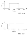
- FIGS. 6( a ) and 6 ( b ) are signal waveform illustrating an example of the PWM technique of the embodiment in FIG. 5 .
- a method of inverter linearization in electric motors through secondary modulation of a motor voltage command thereto.
- the method overcomes the aforementioned problems by interpolating between two known “good” operating points through a secondary, time-based domain modulation.
- a first good operating point is established as a defined threshold voltage command value, wherein the motor is considered to exhibit acceptable torque ripple and linearity at values above the threshold. At values below the threshold, the torque ripple and linearity is considered unacceptable.
- the second good operating point is defined at the “zero” command, at which point the inverter also produces very low torque ripple.
- a time based modulation is implemented wherein the command is modulated to the threshold value for a period of time proportional to the relationship between the actual desired value and the threshold value.
- the electric power steering system 12 may include a conventional rack and pinion steering mechanism 14 having a toothed rack 15 and a pinion gear (not shown) under a gear housing 16 .
- a conventional rack and pinion steering mechanism 14 having a toothed rack 15 and a pinion gear (not shown) under a gear housing 16 .
- an upper steering shaft 20 turns a lower shaft 22 through a universal joint 24 .
- the lower steering shaft 22 turns the pinion gear.
- the rotation of the pinion gear moves the pinion rack 15 , which then moves tie rods 28 (only one shown).
- tie rods 28 move steering knuckles 30 (only one shown) to turn wheels 32 .
- An electric power assist is provided through a controller 34 and a power assist actuator comprising a motor 36 .
- the controller 34 receives electric power from a vehicle electric power source 38 through a connection 40 .
- the controller 34 also receives a signal 41 representative of the vehicle velocity, as well as steering pinion gear angle signal 44 from a rotational position sensor 42 .
- a torque sensor 46 senses the torque applied to steering wheel 18 by the vehicle operator and provides an operator torque signal 48 to the controller 34 .
- rotor position signals 50 are generated within the motor 36 and are also provided to the controller 34 .
- the controller 34 derives desired motor phase voltages.
- the motor phase voltages are provided to motor 36 through a bus 52 , thereby providing torque assist to steering shaft 20 through worm 54 and worm gear 56 .
- the controller 34 is configured to develop the necessary voltage(s) to be applied to the motor 36 such that the desired torque is generated.
- a storage medium 58 may be used to contain instructions for executing a computer-implemented process within controller 34 , through the transmission of data signal(s) 60 therebetween.
- FIG. 2 is a block diagram of an exemplary PM motor control system 100 that may be used for controlling the torque of a sinusoidally excited PM electric machine, such as the EPS motor 36 of FIG. 1 .
- the control system 100 includes (but is not limited to) motor 36 , a motor rotor position/velocity sensor assembly 102 , the controller 34 , a power circuit or inverter 106 and power supply 108 .
- the velocity sensing portion of sensor assembly 102 may be embodied by a circuit or algorithm, for example.
- the controller 34 is configured and connected to develop the necessary voltage(s) out of inverter 106 such that, when applied to the motor 36 , the desired torque is generated.
- the sensor assembly 102 is connected to the motor 36 to detect the angular position, ⁇ , of the rotor.
- the sensor assembly 102 may sense the rotary position based on optical detection, magnetic field variations, or other methodologies. Exemplary position sensors include potentiometers, resolvers, synchros, encoders, and the like.
- the sensor assembly 102 outputs a position signal 110 indicating the angular position of the rotor.
- the motor speed may be measured, calculated, or otherwise derived from a combination thereof.
- the motor speed ⁇ is calculated as the change of the motor position ⁇ as measured by the sensor assembly 102 over a prescribed time interval.
- the sensor assembly 102 determines the speed of the rotor and outputs a corresponding speed signal 112 .
- the position signal 110 , speed signal 112 , and a torque command signal 114 are each applied to the controller 34 .
- the torque command signal 114 is representative of the desired motor torque value for the assist motor 36 .
- the controller 34 determines a voltage command amplitude V ref (shown as signal 116 ) and its phase advance angle ⁇ needed to develop the desired torque according to the torque command signal 114 , the position signal 110 and the speed signal 112 , as well as other fixed motor parameter values.
- the controller 34 could also include a linearization function block that provides a linearization offset function for V ref 116 in order to minimize torque ripple.
- V a V ref *V ph — Profile ( ⁇ a )
- V b V ref *V ph — Profile ( ⁇ b )
- V c V ref *V ph — Profile ( ⁇ c )
- V ph — Profile ( ⁇ a ) V ph — Profile ( ⁇ b )
- V ph — Profile ( ⁇ c ) are profile voltages generated from the sine functions as shown in the following equations:
- V ph — Profile ( ⁇ a ) Sin( ⁇ a ) ⁇ min[sin( ⁇ a ),
- phase advancing angle ⁇ may also be calculated as a function of the input signal for torque or speed.
- the phase advancing angle ⁇ is defined as the angle between the phase voltage vector V and back electromotive force (EMF) vector E as generated by the motor 36 as it rotates.
- the phase voltage signals V a , V b , and V c are phase shifted by the phase advancing angle ⁇ .
- Phase voltage command signals V a , V b , and V c are used to generate the motor duty cycle commands D a , D b , and D c 118 using an appropriate pulse width modulation (PWM) technique.
- PWM pulse width modulation
- Motor duty cycle commands 118 of the controller 34 are processed into on-off control command signals applied to the respective switching devices of the power circuit or inverter 106 , which is coupled with a power supply 108 to apply modulated phase voltage signals 120 to the stator windings of the motor in response to the motor voltage command signals.
- FIG. 3 is a modified block diagram of the exemplary PM motor control system 100 shown in FIG. 2 , with the addition of a secondary modulation block 130 for implementing the above mentioned, secondary time based modulation of a target voltage command signal 115 (the same as the previous voltage command signal V ref 116 in FIG. 2 ) at relatively low voltage commands.
- This secondary modulation is implemented before the phase angle ⁇ information is combined with a new modulated voltage command signal once again denoted as V ref 116 to derive the individual phase voltage command signals, and is carried out only when the value of the desired voltage command signal V desired 115 is below a threshold value.
- the method 200 includes an algorithm that commences at block 202 by beginning secondary modulation calculations to determine whether the secondary modulation will be implemented, under the conditions described above.
- various inputs used by the algorithm are received. These inputs are representative of actual system inputs, such as the desired voltage command signal V desired 115 and the voltage command threshold value (V th ) at which it is determined there is satisfactory torque ripple and linearity performance in the system. More specifically, the values representing V desired 115 are Modulation_Sign and Modulation_Index, which respectively represent the sign and the magnitude of V desired 115 .
- the threshold voltage V th is represented by the variable entitled Modulation_Index_Threshold. It will be appreciated that the specific value of Modulation_Index_Threshold calibrated into the algorithm may be determined empirically, by simulation or other suitable means.
- the algorithm determines the variable entitled Secondary_Modulation, which is the ratio of Modulation_Index to Modulation_Index_Threshold. In other words, this ratio compares the desired voltage command signal V desired 115 to the threshold voltage to see whether secondary modulation will be carried out.
- the algorithm proceeds to block 210 , where the desired voltage command signal V desired 115 information is passed through for conversion to phase voltage command processing. Specifically, the value of Modulation_Index is combined with the value of Modulation_Sign and thereafter passed along to the inverter. Further, at block 212 , an interrupt timer is disabled, the function of which is described hereinafter.
- the secondary modulation subroutine exits at block 214 .
- the algorithm proceeds to block 216 , where the desired voltage command signal V desired 115 is modulated to the threshold value. That is, Modulation_Index is now set equal to Modulation_Index_Threshold (the first “good” operating point), multiplied by the value of Modulation_Sign. However, in order to accurately derive the modulated voltage command signal V ref 116 , the desired voltage command signal V desired 115 is at some point be modulated to zero (the second “good” operating point) prior to the expiration of the nominal sample period of the signal (e.g., 2 milliseconds).
- the calibration Sample_period is also shown in block 204 .
- the variable Interrupt_Timer is calculated, which determines the amount of time within the sample period that the command signal is held at the threshold value. This variable directly correlates with how close the desired voltage command signal V desired 115 is to the threshold voltage. For example, if the desired voltage command signal V desired 115 is 90% of the threshold voltage, then the desired voltage command signal V desired 115 is modulated to the threshold voltage for the first 90% of the sample period (e.g., 1.8 ms), and then modulated to zero for the remaining 10% of the sample period (e.g., 0.2 ms) to form the resulting modulated voltage command signal V ref 116 .
- An interrupt subroutine is shown at block 220 , during which time Modulation_Index is set to zero at block 222 .
- FIG. 5 illustrates an alternative embodiment of the algorithm in FIG. 4 .
- the method 200 proceeds to block 230 , where the start time information is obtained.
- the start time may be one of a number of individual, preselected start times that changes with each successive sample period. For example, with a sample period of 2000 ⁇ s (2 milliseconds), the algorithm could be configured such that the start time may begin anywhere within that period.
- the start time index is incremented such that a different start time will be obtained during the next sample period.
- the amount of time that the desired voltage command signal V desired 115 is held at the threshold value (On_Time) is determined by Secondary_Modulation multiplied by Sample_Period, as shown at block 234 .
- the end time (End_Time) is computed by adding the start time to the on time, as shown at block 236 . The end time will determine the point in time at which the desired voltage command signal V desired 115 is modulated back to zero. Proceeding to block 238 , the modulation index is set to the threshold value multiplied by the directional sign.
- the end time is in effect “wrapped around” to the beginning of the sample period.
- the desired voltage command signal V desired 115 is posted at the threshold value to begin the sample period.
- the end time is then recomputed at block 250 to be the difference between the old end time less the sample period.
- the end time interrupt subroutine will be activated, wherein the desired voltage command signal V desired 115 is modulated to zero.
- the start time will be reached, at which time the desired voltage command signal V desired 115 will again be modulated back to the threshold value for the remainder of the sample period.
- FIGS. 6( a ) and 6 ( b ) are timing diagrams that provide an illustrative example of the PWM technique used in the algorithm of FIG. 5 .
- the exemplary sample period is 2000 ⁇ s and the start time is selected at 500 ⁇ s.
- FIG. 6( a ) illustrates the resulting modulated voltage command signal V ref 116 waveform when the secondary modulation is determined to be 50% (i.e., the total on time for the threshold voltage is 1000 ⁇ s).
- the end time is the start time plus the on time, or 1500 ⁇ s. Since this total does not exceed the sample period of 2000 ⁇ s, there is no need to recompute the end time.
- the sample period begins with Modulation_Index being modulated at zero (block 242 ). Then, at the start time of 500 ⁇ s, the start time interrupt block 244 causes Modulation_Index to be modulated up to the signed threshold value for a duration of 1000 ⁇ s, after which time the end time interrupt block modulates the signal back to zero for the remaining 500 ⁇ s in the sample period.
- the output is at the threshold value.
- the potential for audible noise is reduced by minimizing the operating space where such noise might occur, since the operating range benefiting most from the technique is dominated by Coulomb friction and where the output of the inverter has a relatively low gain.
- This modulation technique is different than existing techniques in that, among other aspects, it is imposed before the phase angle information is combined with the motor voltage command signal 116 and occurs only when the desired voltage command signal value V desired 115 is below the threshold value.
- the disclosed invention can be embodied in the form of computer or controller implemented processes and apparatuses for practicing those processes.
- the present invention can also be embodied in the form of computer program code containing instructions embodied in tangible media 58 , such as floppy diskettes, CD-ROMs, hard drives, or any other computer-readable storage medium, wherein, when the computer program code is loaded into and executed by a computer or controller, the computer becomes an apparatus for practicing the invention.
- the present invention may also be embodied in the form of computer program code or signal 60 , for example, whether stored in a storage medium, loaded into and/or executed by a computer or controller, or transmitted over some transmission medium, such as over electrical wiring or cabling, through fiber optics, or via electromagnetic radiation, wherein, when the computer program code is loaded into and executed by a computer, the computer becomes an apparatus for practicing the invention.
- the computer program code segments configure the microprocessor to create specific logic circuits.
Abstract
Description
V a =V ref *V ph
V b =V ref *V ph
V c =V ref *V ph
where Vph
V ph
V ph
V ph
θa=θa+δ
θb=θa+120°
θc=θb+120°
Claims (12)
Priority Applications (3)
| Application Number | Priority Date | Filing Date | Title |
|---|---|---|---|
| US10/458,091 US7190135B2 (en) | 2002-06-26 | 2003-06-10 | Method of inverter linearization in electric machines through secondary modulation |
| EP03741972A EP1575817A4 (en) | 2002-06-26 | 2003-06-11 | Method of inverter linearization in electric machines through se condary modulation |
| PCT/US2003/018737 WO2004002804A2 (en) | 2002-06-26 | 2003-06-11 | Method of inverter linearization in electric machines through secondary modulation |
Applications Claiming Priority (2)
| Application Number | Priority Date | Filing Date | Title |
|---|---|---|---|
| US39156202P | 2002-06-26 | 2002-06-26 | |
| US10/458,091 US7190135B2 (en) | 2002-06-26 | 2003-06-10 | Method of inverter linearization in electric machines through secondary modulation |
Publications (2)
| Publication Number | Publication Date |
|---|---|
| US20040000889A1 US20040000889A1 (en) | 2004-01-01 |
| US7190135B2 true US7190135B2 (en) | 2007-03-13 |
Family
ID=29782621
Family Applications (1)
| Application Number | Title | Priority Date | Filing Date |
|---|---|---|---|
| US10/458,091 Expired - Fee Related US7190135B2 (en) | 2002-06-26 | 2003-06-10 | Method of inverter linearization in electric machines through secondary modulation |
Country Status (3)
| Country | Link |
|---|---|
| US (1) | US7190135B2 (en) |
| EP (1) | EP1575817A4 (en) |
| WO (1) | WO2004002804A2 (en) |
Cited By (4)
| Publication number | Priority date | Publication date | Assignee | Title |
|---|---|---|---|---|
| US20070165432A1 (en) * | 2003-07-31 | 2007-07-19 | Denso Corporation | Voltage conversion device and computer-readable recording medium having program recorded thereon for computer to control voltage conversion by voltage conversion device |
| US20090009112A1 (en) * | 2006-02-14 | 2009-01-08 | Uwe Klippert | Drive Device for an Adjusting Device for Adjusting a Vehicle Part and Method for Operating a Drive Device |
| US20090284194A1 (en) * | 2008-05-13 | 2009-11-19 | Stmicroelectronics S.R.L. | Phase current measurements in a three phase inverter using a single common dc-link current sensor |
| US11424971B2 (en) * | 2020-07-07 | 2022-08-23 | Dr. Ing. H.C. F. Porsche Aktiengesellschaft | Control unit for generating PWM pulses for an inverter |
Families Citing this family (3)
| Publication number | Priority date | Publication date | Assignee | Title |
|---|---|---|---|---|
| US7202622B2 (en) * | 2002-04-30 | 2007-04-10 | International Rectifier Corporation | Method for controlling an electric motor to reduce EMI |
| TWI277287B (en) * | 2005-07-22 | 2007-03-21 | Delta Electronics Inc | Motor control device |
| US20090304086A1 (en) * | 2008-06-06 | 2009-12-10 | Apple Inc. | Method and system for video coder and decoder joint optimization |
Citations (27)
| Publication number | Priority date | Publication date | Assignee | Title |
|---|---|---|---|---|
| US4047083A (en) * | 1976-03-08 | 1977-09-06 | General Electric Company | Adjustable speed A-C motor drive with smooth transition between operational modes and with reduced harmonic distortion |
| US4972320A (en) * | 1986-09-29 | 1990-11-20 | Hitachi, Ltd. | Motor-driven power steering apparatus |
| US5329217A (en) * | 1992-12-30 | 1994-07-12 | Allen-Bradley Company, Inc. | Compensated feedforward voltage for a PWM AC motor drive |
| US5589805A (en) | 1995-11-06 | 1996-12-31 | General Motors Corporation | Enhanced resolution pulse width modulation control |
| US5610806A (en) * | 1995-06-19 | 1997-03-11 | Allen-Bradley Company, Inc. | Pulse width modulation method for driving three phase power inverter/converter switches with balanced discontinuous phase commands |
| US5657216A (en) * | 1995-11-13 | 1997-08-12 | Allen-Bradley Company, Inc. | Method and apparatus for linearizing pulse width modulation in overmodulation region |
| US5736825A (en) * | 1996-06-25 | 1998-04-07 | Allen-Bradley Company, Inc. | Method and apparatus for linearizing pulse width modulation by modifying command voltges |
| US5900706A (en) * | 1997-01-29 | 1999-05-04 | Fuji Xerox Co., Ltd. | Motor drive control apparatus |
| US6198296B1 (en) | 1999-01-14 | 2001-03-06 | Burr-Brown Corporation | Bridge sensor linearization circuit and method |
| WO2001020751A2 (en) * | 1999-09-17 | 2001-03-22 | Delphi Technologies, Inc. | Brushless machines using optimal phase angle control |
| US6208497B1 (en) | 1997-06-26 | 2001-03-27 | Venture Scientifics, Llc | System and method for servo control of nonlinear electromagnetic actuators |
| US6225774B1 (en) * | 1997-06-10 | 2001-05-01 | Hitachi, Ltd. | Motor control method and motor control system |
| US6232730B1 (en) * | 1998-06-05 | 2001-05-15 | Matsushita Electric Industrial Co., Ltd. | Brushless motor driving circuit and a method of controlling the brushless motor driving circuit |
| US6281656B1 (en) * | 1998-09-30 | 2001-08-28 | Hitachi, Ltd. | Synchronous motor control device electric motor vehicle control device and method of controlling synchronous motor |
| US6288814B1 (en) | 1994-05-19 | 2001-09-11 | Ortel Corporation | In-line predistorter for linearization of electronic and optical signals |
| US6307336B1 (en) * | 1999-09-27 | 2001-10-23 | Mts Systems Corporation | Closed loop control of PWM duty cycle |
| US6337599B2 (en) | 1999-12-30 | 2002-01-08 | Lg Electronics, Inc. | Predistortion linearizer for power amplifier |
| US6340914B1 (en) | 2000-04-05 | 2002-01-22 | Nortel Networks Limited | Pilot-assisted amplifier linearization circuit |
| US6362585B1 (en) * | 2000-05-30 | 2002-03-26 | General Motors Corporation | Controlling electric vehicle DC bus voltage ripple under step mode of operation |
| US6426602B1 (en) * | 1999-09-16 | 2002-07-30 | Delphi Technologies, Inc. | Minimization of motor torque ripple due to unbalanced conditions |
| US6441578B1 (en) | 1999-09-16 | 2002-08-27 | Delphi Technologies, Inc. | Method and apparatus for torque linearization in an electric power steering system |
| US6541933B1 (en) * | 2001-11-20 | 2003-04-01 | Rockwell Automation Technologies, Inc. | Angle control of modulating wave to reduce reflected wave overvoltage transients |
| US6563378B1 (en) | 2000-05-19 | 2003-05-13 | Jam Technologies, Llc | Digital amplifier linearization using analog feedback |
| US6690135B2 (en) * | 2002-01-24 | 2004-02-10 | Delphi Technologies, Inc. | Method for compensating for dead time non-linearities in a pulse width modulation controlled switching scheme |
| US6694287B2 (en) * | 2001-08-30 | 2004-02-17 | Delphi Technologies, Inc. | Phase angle diagnostics for sinusoidal controlled electric machine |
| US6727669B2 (en) * | 2001-09-18 | 2004-04-27 | Toyoda Koki Kabushiki Kaisha | Motor-driven power steering apparatus |
| US6798161B2 (en) * | 2002-04-26 | 2004-09-28 | Toyoda Koki Kabushiki Kaisha | Motor control device |
-
2003
- 2003-06-10 US US10/458,091 patent/US7190135B2/en not_active Expired - Fee Related
- 2003-06-11 EP EP03741972A patent/EP1575817A4/en not_active Withdrawn
- 2003-06-11 WO PCT/US2003/018737 patent/WO2004002804A2/en active Search and Examination
Patent Citations (28)
| Publication number | Priority date | Publication date | Assignee | Title |
|---|---|---|---|---|
| US4047083A (en) * | 1976-03-08 | 1977-09-06 | General Electric Company | Adjustable speed A-C motor drive with smooth transition between operational modes and with reduced harmonic distortion |
| US4972320A (en) * | 1986-09-29 | 1990-11-20 | Hitachi, Ltd. | Motor-driven power steering apparatus |
| US5329217A (en) * | 1992-12-30 | 1994-07-12 | Allen-Bradley Company, Inc. | Compensated feedforward voltage for a PWM AC motor drive |
| US6288814B1 (en) | 1994-05-19 | 2001-09-11 | Ortel Corporation | In-line predistorter for linearization of electronic and optical signals |
| US5610806A (en) * | 1995-06-19 | 1997-03-11 | Allen-Bradley Company, Inc. | Pulse width modulation method for driving three phase power inverter/converter switches with balanced discontinuous phase commands |
| US5589805A (en) | 1995-11-06 | 1996-12-31 | General Motors Corporation | Enhanced resolution pulse width modulation control |
| US5657216A (en) * | 1995-11-13 | 1997-08-12 | Allen-Bradley Company, Inc. | Method and apparatus for linearizing pulse width modulation in overmodulation region |
| US5736825A (en) * | 1996-06-25 | 1998-04-07 | Allen-Bradley Company, Inc. | Method and apparatus for linearizing pulse width modulation by modifying command voltges |
| US5900706A (en) * | 1997-01-29 | 1999-05-04 | Fuji Xerox Co., Ltd. | Motor drive control apparatus |
| US6225774B1 (en) * | 1997-06-10 | 2001-05-01 | Hitachi, Ltd. | Motor control method and motor control system |
| US6208497B1 (en) | 1997-06-26 | 2001-03-27 | Venture Scientifics, Llc | System and method for servo control of nonlinear electromagnetic actuators |
| US6232730B1 (en) * | 1998-06-05 | 2001-05-15 | Matsushita Electric Industrial Co., Ltd. | Brushless motor driving circuit and a method of controlling the brushless motor driving circuit |
| US20020043953A1 (en) * | 1998-09-30 | 2002-04-18 | Hitachi, Ltd. | Synchronous motor control device, electric motor vehicle control device and method of controlling synchronous motor |
| US6281656B1 (en) * | 1998-09-30 | 2001-08-28 | Hitachi, Ltd. | Synchronous motor control device electric motor vehicle control device and method of controlling synchronous motor |
| US6198296B1 (en) | 1999-01-14 | 2001-03-06 | Burr-Brown Corporation | Bridge sensor linearization circuit and method |
| US6441578B1 (en) | 1999-09-16 | 2002-08-27 | Delphi Technologies, Inc. | Method and apparatus for torque linearization in an electric power steering system |
| US6426602B1 (en) * | 1999-09-16 | 2002-07-30 | Delphi Technologies, Inc. | Minimization of motor torque ripple due to unbalanced conditions |
| WO2001020751A2 (en) * | 1999-09-17 | 2001-03-22 | Delphi Technologies, Inc. | Brushless machines using optimal phase angle control |
| US6307336B1 (en) * | 1999-09-27 | 2001-10-23 | Mts Systems Corporation | Closed loop control of PWM duty cycle |
| US6337599B2 (en) | 1999-12-30 | 2002-01-08 | Lg Electronics, Inc. | Predistortion linearizer for power amplifier |
| US6340914B1 (en) | 2000-04-05 | 2002-01-22 | Nortel Networks Limited | Pilot-assisted amplifier linearization circuit |
| US6563378B1 (en) | 2000-05-19 | 2003-05-13 | Jam Technologies, Llc | Digital amplifier linearization using analog feedback |
| US6362585B1 (en) * | 2000-05-30 | 2002-03-26 | General Motors Corporation | Controlling electric vehicle DC bus voltage ripple under step mode of operation |
| US6694287B2 (en) * | 2001-08-30 | 2004-02-17 | Delphi Technologies, Inc. | Phase angle diagnostics for sinusoidal controlled electric machine |
| US6727669B2 (en) * | 2001-09-18 | 2004-04-27 | Toyoda Koki Kabushiki Kaisha | Motor-driven power steering apparatus |
| US6541933B1 (en) * | 2001-11-20 | 2003-04-01 | Rockwell Automation Technologies, Inc. | Angle control of modulating wave to reduce reflected wave overvoltage transients |
| US6690135B2 (en) * | 2002-01-24 | 2004-02-10 | Delphi Technologies, Inc. | Method for compensating for dead time non-linearities in a pulse width modulation controlled switching scheme |
| US6798161B2 (en) * | 2002-04-26 | 2004-09-28 | Toyoda Koki Kabushiki Kaisha | Motor control device |
Non-Patent Citations (1)
| Title |
|---|
| PCT Search Report, PCT/US03/18737, mailed Jul. 6, 2005. |
Cited By (7)
| Publication number | Priority date | Publication date | Assignee | Title |
|---|---|---|---|---|
| US20070165432A1 (en) * | 2003-07-31 | 2007-07-19 | Denso Corporation | Voltage conversion device and computer-readable recording medium having program recorded thereon for computer to control voltage conversion by voltage conversion device |
| US7869233B2 (en) * | 2003-07-31 | 2011-01-11 | Toyota Jidosha Kabushiki Kaisha | Voltage conversion device and computer-readable recording medium having program recorded thereon for computer to control voltage conversion by voltage conversion device |
| US20090009112A1 (en) * | 2006-02-14 | 2009-01-08 | Uwe Klippert | Drive Device for an Adjusting Device for Adjusting a Vehicle Part and Method for Operating a Drive Device |
| US8390224B2 (en) * | 2006-02-14 | 2013-03-05 | Brose Fahrzeugteile Gmbh & Co. Kg, Coburg | Drive device for an adjusting device for adjusting a vehicle part and method for operating a drive device |
| US20090284194A1 (en) * | 2008-05-13 | 2009-11-19 | Stmicroelectronics S.R.L. | Phase current measurements in a three phase inverter using a single common dc-link current sensor |
| US8134327B2 (en) * | 2008-05-13 | 2012-03-13 | Stmicroelectronics S.R.L. | Phase current measurements in a three phase inverter using a single common DC-link current sensor |
| US11424971B2 (en) * | 2020-07-07 | 2022-08-23 | Dr. Ing. H.C. F. Porsche Aktiengesellschaft | Control unit for generating PWM pulses for an inverter |
Also Published As
| Publication number | Publication date |
|---|---|
| EP1575817A4 (en) | 2012-01-18 |
| EP1575817A3 (en) | 2005-10-12 |
| EP1575817A2 (en) | 2005-09-21 |
| WO2004002804A2 (en) | 2004-01-08 |
| WO2004002804A3 (en) | 2005-08-25 |
| US20040000889A1 (en) | 2004-01-01 |
Similar Documents
| Publication | Publication Date | Title |
|---|---|---|
| US6914399B2 (en) | Active deadtime control for improved torque ripple performance in electric machines | |
| US6465975B1 (en) | Method and system for controlling torque in permanent magnet brushless electric motors | |
| US7157878B2 (en) | Transient compensation voltage estimation for feedforward sinusoidal brushless motor control | |
| US6781333B2 (en) | Drive control apparatus and method of alternating current motor | |
| EP1470988B1 (en) | Electric power steering apparatus | |
| US7119530B2 (en) | Motor phase current measurement using a single DC bus shunt sensor | |
| US20030062868A1 (en) | Switching methodology for ground referenced voltage controlled electric machine | |
| CN104052344B (en) | Rotary electric machine controller and electric power steering apparatus | |
| US7065437B2 (en) | Current limit for an electric machine | |
| US7190135B2 (en) | Method of inverter linearization in electric machines through secondary modulation | |
| JP4504893B2 (en) | Electric power steering device | |
| JP4385276B2 (en) | Motor control device | |
| JP2009080002A (en) | Turning angle detector and electric power steering device using the same | |
| CN111010057B (en) | Inverter commutation technique for five-step motor drive | |
| JP7090812B2 (en) | Control device for AC rotary electric machine and electric power steering device | |
| JP2009136034A (en) | Motor control device | |
| US20200395882A1 (en) | Electric power steering apparatus | |
| CN110855206B (en) | Motor current limitation of permanent magnet synchronous motor | |
| JP2021027673A (en) | Motor control device and steering device | |
| JPH04251592A (en) | Controller of wheel driving motor for electric vehicle | |
| US20220073129A1 (en) | Angle detector, ac-rotating-machine controller, and electric power steering apparatus | |
| WO2022190582A1 (en) | Motor drive device | |
| US11190126B2 (en) | Space vector pulse width modulation for multi-phase machines | |
| JP2000050677A (en) | Position sensorless control equipment for permanent magnet type synchronous motor | |
| EP3978881A1 (en) | Angle detector, ac rotating machine control device, and electric power steering device |
Legal Events
| Date | Code | Title | Description |
|---|---|---|---|
| AS | Assignment |
Owner name: DELPHI TECHNOLOGIES, INC., MICHIGAN Free format text: ASSIGNMENT OF ASSIGNORS INTEREST;ASSIGNOR:COLLIER-HALLMAN, STEVEN JAMES;REEL/FRAME:014173/0398 Effective date: 20030605 |
|
| STCF | Information on status: patent grant |
Free format text: PATENTED CASE |
|
| AS | Assignment |
Owner name: GM GLOBAL TECHNOLOGY OPERATIONS, INC., MICHIGAN Free format text: ASSIGNMENT OF ASSIGNORS INTEREST;ASSIGNOR:DELPHI TECHNOLOGIES, INC.;REEL/FRAME:023449/0065 Effective date: 20091002 Owner name: GM GLOBAL TECHNOLOGY OPERATIONS, INC.,MICHIGAN Free format text: ASSIGNMENT OF ASSIGNORS INTEREST;ASSIGNOR:DELPHI TECHNOLOGIES, INC.;REEL/FRAME:023449/0065 Effective date: 20091002 |
|
| AS | Assignment |
Owner name: GM GLOBAL TECHNOLOGY OPERATIONS, INC.,MICHIGAN Free format text: ASSIGNMENT OF ASSIGNORS INTEREST;ASSIGNOR:DELPHI TECHNOLOGIES, INC.;REEL/FRAME:023988/0754 Effective date: 20091002 Owner name: UNITED STATES DEPARTMENT OF THE TREASURY,DISTRICT Free format text: SECURITY AGREEMENT;ASSIGNOR:GM GLOBAL TECHNOLOGY OPERATIONS, INC.;REEL/FRAME:023990/0349 Effective date: 20090710 Owner name: UAW RETIREE MEDICAL BENEFITS TRUST,MICHIGAN Free format text: SECURITY AGREEMENT;ASSIGNOR:GM GLOBAL TECHNOLOGY OPERATIONS, INC.;REEL/FRAME:023990/0831 Effective date: 20090710 Owner name: GM GLOBAL TECHNOLOGY OPERATIONS, INC., MICHIGAN Free format text: ASSIGNMENT OF ASSIGNORS INTEREST;ASSIGNOR:DELPHI TECHNOLOGIES, INC.;REEL/FRAME:023988/0754 Effective date: 20091002 Owner name: UNITED STATES DEPARTMENT OF THE TREASURY, DISTRICT Free format text: SECURITY AGREEMENT;ASSIGNOR:GM GLOBAL TECHNOLOGY OPERATIONS, INC.;REEL/FRAME:023990/0349 Effective date: 20090710 Owner name: UAW RETIREE MEDICAL BENEFITS TRUST, MICHIGAN Free format text: SECURITY AGREEMENT;ASSIGNOR:GM GLOBAL TECHNOLOGY OPERATIONS, INC.;REEL/FRAME:023990/0831 Effective date: 20090710 |
|
| AS | Assignment |
Owner name: GM GLOBAL TECHNOLOGY OPERATIONS, INC., MICHIGAN Free format text: ASSIGNMENT OF ASSIGNORS INTEREST;ASSIGNOR:DELPHI TECHNOLOGIES, INC.;REEL/FRAME:025204/0846 Effective date: 20101014 |
|
| REMI | Maintenance fee reminder mailed | ||
| FPAY | Fee payment |
Year of fee payment: 4 |
|
| SULP | Surcharge for late payment | ||
| AS | Assignment |
Owner name: GM GLOBAL TECHNOLOGY OPERATIONS, INC., MICHIGAN Free format text: RELEASE BY SECURED PARTY;ASSIGNOR:UNITED STATES DEPARTMENT OF THE TREASURY;REEL/FRAME:025386/0591 Effective date: 20100420 Owner name: GM GLOBAL TECHNOLOGY OPERATIONS, INC., MICHIGAN Free format text: RELEASE BY SECURED PARTY;ASSIGNOR:UAW RETIREE MEDICAL BENEFITS TRUST;REEL/FRAME:025386/0503 Effective date: 20101026 |
|
| AS | Assignment |
Owner name: PACIFIC CENTURY MOTORS, INC., CHINA Free format text: ASSIGNMENT OF ASSIGNORS INTEREST;ASSIGNOR:GM GLOBAL TECHNOLOGY OPERATIONS, INC.;REEL/FRAME:027842/0918 Effective date: 20101130 Owner name: GM GLOBAL TECHNOLOGY OPERATIONS, INC., MICHIGAN Free format text: ASSIGNMENT OF ASSIGNORS INTEREST;ASSIGNOR:GM GLOBAL TECHNOLOGY OPERATIONS, INC.;REEL/FRAME:027842/0918 Effective date: 20101130 |
|
| AS | Assignment |
Owner name: STEERING SOLUTIONS IP HOLDING CORPORATION, MICHIGA Free format text: ASSIGNMENT OF ASSIGNORS INTEREST;ASSIGNORS:PACIFIC CENTURY MOTORS, INC.;NEXTEER (BEIJING) TECHNOLOGY CO., LTD.;REEL/FRAME:027870/0666 Effective date: 20120126 |
|
| FPAY | Fee payment |
Year of fee payment: 8 |
|
| FEPP | Fee payment procedure |
Free format text: MAINTENANCE FEE REMINDER MAILED (ORIGINAL EVENT CODE: REM.); ENTITY STATUS OF PATENT OWNER: LARGE ENTITY |
|
| LAPS | Lapse for failure to pay maintenance fees |
Free format text: PATENT EXPIRED FOR FAILURE TO PAY MAINTENANCE FEES (ORIGINAL EVENT CODE: EXP.); ENTITY STATUS OF PATENT OWNER: LARGE ENTITY |
|
| STCH | Information on status: patent discontinuation |
Free format text: PATENT EXPIRED DUE TO NONPAYMENT OF MAINTENANCE FEES UNDER 37 CFR 1.362 |
|
| FP | Lapsed due to failure to pay maintenance fee |
Effective date: 20190313 |