US7167775B2 - Robotic vacuum cleaner - Google Patents
Robotic vacuum cleaner Download PDFInfo
- Publication number
- US7167775B2 US7167775B2 US10/007,103 US710301A US7167775B2 US 7167775 B2 US7167775 B2 US 7167775B2 US 710301 A US710301 A US 710301A US 7167775 B2 US7167775 B2 US 7167775B2
- Authority
- US
- United States
- Prior art keywords
- area
- scanning
- scanning pattern
- point
- path
- Prior art date
- Legal status (The legal status is an assumption and is not a legal conclusion. Google has not performed a legal analysis and makes no representation as to the accuracy of the status listed.)
- Expired - Fee Related, expires
Links
- 238000010407 vacuum cleaning Methods 0.000 claims abstract description 13
- 238000000034 method Methods 0.000 claims description 56
- 238000004891 communication Methods 0.000 claims description 12
- 238000004140 cleaning Methods 0.000 abstract description 14
- 238000001514 detection method Methods 0.000 description 24
- 230000008569 process Effects 0.000 description 20
- 238000001914 filtration Methods 0.000 description 14
- 230000007246 mechanism Effects 0.000 description 14
- 239000002184 metal Substances 0.000 description 11
- 229910052751 metal Inorganic materials 0.000 description 11
- 238000012545 processing Methods 0.000 description 10
- 238000010586 diagram Methods 0.000 description 9
- 239000002245 particle Substances 0.000 description 7
- 230000008878 coupling Effects 0.000 description 6
- 238000010168 coupling process Methods 0.000 description 6
- 238000005859 coupling reaction Methods 0.000 description 6
- 230000035939 shock Effects 0.000 description 6
- 239000004033 plastic Substances 0.000 description 5
- 229920003023 plastic Polymers 0.000 description 5
- 230000001133 acceleration Effects 0.000 description 4
- 230000008859 change Effects 0.000 description 4
- 238000010276 construction Methods 0.000 description 4
- 239000000463 material Substances 0.000 description 4
- 239000004677 Nylon Substances 0.000 description 3
- 235000004443 Ricinus communis Nutrition 0.000 description 3
- 229920001778 nylon Polymers 0.000 description 3
- 230000003068 static effect Effects 0.000 description 3
- 230000005355 Hall effect Effects 0.000 description 2
- 238000013019 agitation Methods 0.000 description 2
- 230000009849 deactivation Effects 0.000 description 2
- 238000006073 displacement reaction Methods 0.000 description 2
- 238000009826 distribution Methods 0.000 description 2
- 238000005516 engineering process Methods 0.000 description 2
- 230000005484 gravity Effects 0.000 description 2
- 229920001903 high density polyethylene Polymers 0.000 description 2
- 239000004700 high-density polyethylene Substances 0.000 description 2
- 230000000670 limiting effect Effects 0.000 description 2
- 238000004519 manufacturing process Methods 0.000 description 2
- 238000005259 measurement Methods 0.000 description 2
- 229920000915 polyvinyl chloride Polymers 0.000 description 2
- 239000004800 polyvinyl chloride Substances 0.000 description 2
- 230000000284 resting effect Effects 0.000 description 2
- 238000003860 storage Methods 0.000 description 2
- 230000000153 supplemental effect Effects 0.000 description 2
- 230000003213 activating effect Effects 0.000 description 1
- 239000000853 adhesive Substances 0.000 description 1
- 230000001070 adhesive effect Effects 0.000 description 1
- 230000009194 climbing Effects 0.000 description 1
- 238000007796 conventional method Methods 0.000 description 1
- 230000006378 damage Effects 0.000 description 1
- 230000007423 decrease Effects 0.000 description 1
- 238000011161 development Methods 0.000 description 1
- 230000000694 effects Effects 0.000 description 1
- 230000005611 electricity Effects 0.000 description 1
- -1 for example Substances 0.000 description 1
- 239000012634 fragment Substances 0.000 description 1
- 238000010413 gardening Methods 0.000 description 1
- 230000002401 inhibitory effect Effects 0.000 description 1
- 238000001746 injection moulding Methods 0.000 description 1
- 238000007689 inspection Methods 0.000 description 1
- 238000009413 insulation Methods 0.000 description 1
- 238000013507 mapping Methods 0.000 description 1
- 239000007769 metal material Substances 0.000 description 1
- 150000002739 metals Chemical class 0.000 description 1
- 238000012544 monitoring process Methods 0.000 description 1
- 230000005019 pattern of movement Effects 0.000 description 1
- 230000035699 permeability Effects 0.000 description 1
- 238000005498 polishing Methods 0.000 description 1
- 238000002360 preparation method Methods 0.000 description 1
- 230000002829 reductive effect Effects 0.000 description 1
- 239000012858 resilient material Substances 0.000 description 1
- 230000004044 response Effects 0.000 description 1
- 238000010408 sweeping Methods 0.000 description 1
- 230000009182 swimming Effects 0.000 description 1
- 239000012780 transparent material Substances 0.000 description 1
- 238000011144 upstream manufacturing Methods 0.000 description 1
Images


Classifications
-
- A—HUMAN NECESSITIES
- A47—FURNITURE; DOMESTIC ARTICLES OR APPLIANCES; COFFEE MILLS; SPICE MILLS; SUCTION CLEANERS IN GENERAL
- A47L—DOMESTIC WASHING OR CLEANING; SUCTION CLEANERS IN GENERAL
- A47L5/00—Structural features of suction cleaners
- A47L5/12—Structural features of suction cleaners with power-driven air-pumps or air-compressors, e.g. driven by motor vehicle engine vacuum
- A47L5/22—Structural features of suction cleaners with power-driven air-pumps or air-compressors, e.g. driven by motor vehicle engine vacuum with rotary fans
- A47L5/28—Suction cleaners with handles and nozzles fixed on the casings, e.g. wheeled suction cleaners with steering handle
- A47L5/34—Suction cleaners with handles and nozzles fixed on the casings, e.g. wheeled suction cleaners with steering handle with height adjustment of nozzles or dust-loosening tools
-
- A—HUMAN NECESSITIES
- A47—FURNITURE; DOMESTIC ARTICLES OR APPLIANCES; COFFEE MILLS; SPICE MILLS; SUCTION CLEANERS IN GENERAL
- A47L—DOMESTIC WASHING OR CLEANING; SUCTION CLEANERS IN GENERAL
- A47L5/00—Structural features of suction cleaners
- A47L5/12—Structural features of suction cleaners with power-driven air-pumps or air-compressors, e.g. driven by motor vehicle engine vacuum
- A47L5/22—Structural features of suction cleaners with power-driven air-pumps or air-compressors, e.g. driven by motor vehicle engine vacuum with rotary fans
- A47L5/28—Suction cleaners with handles and nozzles fixed on the casings, e.g. wheeled suction cleaners with steering handle
- A47L5/30—Suction cleaners with handles and nozzles fixed on the casings, e.g. wheeled suction cleaners with steering handle with driven dust-loosening tools, e.g. rotating brushes
-
- A—HUMAN NECESSITIES
- A47—FURNITURE; DOMESTIC ARTICLES OR APPLIANCES; COFFEE MILLS; SPICE MILLS; SUCTION CLEANERS IN GENERAL
- A47L—DOMESTIC WASHING OR CLEANING; SUCTION CLEANERS IN GENERAL
- A47L9/00—Details or accessories of suction cleaners, e.g. mechanical means for controlling the suction or for effecting pulsating action; Storing devices specially adapted to suction cleaners or parts thereof; Carrying-vehicles specially adapted for suction cleaners
- A47L9/009—Carrying-vehicles; Arrangements of trollies or wheels; Means for avoiding mechanical obstacles
-
- A—HUMAN NECESSITIES
- A47—FURNITURE; DOMESTIC ARTICLES OR APPLIANCES; COFFEE MILLS; SPICE MILLS; SUCTION CLEANERS IN GENERAL
- A47L—DOMESTIC WASHING OR CLEANING; SUCTION CLEANERS IN GENERAL
- A47L9/00—Details or accessories of suction cleaners, e.g. mechanical means for controlling the suction or for effecting pulsating action; Storing devices specially adapted to suction cleaners or parts thereof; Carrying-vehicles specially adapted for suction cleaners
- A47L9/02—Nozzles
- A47L9/04—Nozzles with driven brushes or agitators
- A47L9/0427—Gearing or transmission means therefor
- A47L9/0444—Gearing or transmission means therefor for conveying motion by endless flexible members, e.g. belts
-
- A—HUMAN NECESSITIES
- A47—FURNITURE; DOMESTIC ARTICLES OR APPLIANCES; COFFEE MILLS; SPICE MILLS; SUCTION CLEANERS IN GENERAL
- A47L—DOMESTIC WASHING OR CLEANING; SUCTION CLEANERS IN GENERAL
- A47L9/00—Details or accessories of suction cleaners, e.g. mechanical means for controlling the suction or for effecting pulsating action; Storing devices specially adapted to suction cleaners or parts thereof; Carrying-vehicles specially adapted for suction cleaners
- A47L9/02—Nozzles
- A47L9/04—Nozzles with driven brushes or agitators
- A47L9/0461—Dust-loosening tools, e.g. agitators, brushes
- A47L9/0466—Rotating tools
- A47L9/0477—Rolls
-
- A—HUMAN NECESSITIES
- A47—FURNITURE; DOMESTIC ARTICLES OR APPLIANCES; COFFEE MILLS; SPICE MILLS; SUCTION CLEANERS IN GENERAL
- A47L—DOMESTIC WASHING OR CLEANING; SUCTION CLEANERS IN GENERAL
- A47L9/00—Details or accessories of suction cleaners, e.g. mechanical means for controlling the suction or for effecting pulsating action; Storing devices specially adapted to suction cleaners or parts thereof; Carrying-vehicles specially adapted for suction cleaners
- A47L9/02—Nozzles
- A47L9/04—Nozzles with driven brushes or agitators
- A47L9/0494—Height adjustment of dust-loosening tools
-
- F—MECHANICAL ENGINEERING; LIGHTING; HEATING; WEAPONS; BLASTING
- F04—POSITIVE - DISPLACEMENT MACHINES FOR LIQUIDS; PUMPS FOR LIQUIDS OR ELASTIC FLUIDS
- F04D—NON-POSITIVE-DISPLACEMENT PUMPS
- F04D29/00—Details, component parts, or accessories
- F04D29/26—Rotors specially for elastic fluids
- F04D29/28—Rotors specially for elastic fluids for centrifugal or helico-centrifugal pumps for radial-flow or helico-centrifugal pumps
- F04D29/281—Rotors specially for elastic fluids for centrifugal or helico-centrifugal pumps for radial-flow or helico-centrifugal pumps for fans or blowers
-
- F—MECHANICAL ENGINEERING; LIGHTING; HEATING; WEAPONS; BLASTING
- F04—POSITIVE - DISPLACEMENT MACHINES FOR LIQUIDS; PUMPS FOR LIQUIDS OR ELASTIC FLUIDS
- F04D—NON-POSITIVE-DISPLACEMENT PUMPS
- F04D29/00—Details, component parts, or accessories
- F04D29/26—Rotors specially for elastic fluids
- F04D29/28—Rotors specially for elastic fluids for centrifugal or helico-centrifugal pumps for radial-flow or helico-centrifugal pumps
- F04D29/30—Vanes
-
- G—PHYSICS
- G05—CONTROLLING; REGULATING
- G05D—SYSTEMS FOR CONTROLLING OR REGULATING NON-ELECTRIC VARIABLES
- G05D1/00—Control of position, course or altitude of land, water, air, or space vehicles, e.g. automatic pilot
- G05D1/02—Control of position or course in two dimensions
- G05D1/021—Control of position or course in two dimensions specially adapted to land vehicles
- G05D1/0212—Control of position or course in two dimensions specially adapted to land vehicles with means for defining a desired trajectory
- G05D1/0219—Control of position or course in two dimensions specially adapted to land vehicles with means for defining a desired trajectory ensuring the processing of the whole working surface
-
- G—PHYSICS
- G05—CONTROLLING; REGULATING
- G05D—SYSTEMS FOR CONTROLLING OR REGULATING NON-ELECTRIC VARIABLES
- G05D1/00—Control of position, course or altitude of land, water, air, or space vehicles, e.g. automatic pilot
- G05D1/02—Control of position or course in two dimensions
- G05D1/021—Control of position or course in two dimensions specially adapted to land vehicles
- G05D1/0231—Control of position or course in two dimensions specially adapted to land vehicles using optical position detecting means
- G05D1/0242—Control of position or course in two dimensions specially adapted to land vehicles using optical position detecting means using non-visible light signals, e.g. IR or UV signals
-
- A—HUMAN NECESSITIES
- A46—BRUSHWARE
- A46B—BRUSHES
- A46B13/00—Brushes with driven brush bodies or carriers
- A46B13/001—Cylindrical or annular brush bodies
-
- A—HUMAN NECESSITIES
- A47—FURNITURE; DOMESTIC ARTICLES OR APPLIANCES; COFFEE MILLS; SPICE MILLS; SUCTION CLEANERS IN GENERAL
- A47L—DOMESTIC WASHING OR CLEANING; SUCTION CLEANERS IN GENERAL
- A47L2201/00—Robotic cleaning machines, i.e. with automatic control of the travelling movement or the cleaning operation
- A47L2201/04—Automatic control of the travelling movement; Automatic obstacle detection
-
- G—PHYSICS
- G05—CONTROLLING; REGULATING
- G05D—SYSTEMS FOR CONTROLLING OR REGULATING NON-ELECTRIC VARIABLES
- G05D1/00—Control of position, course or altitude of land, water, air, or space vehicles, e.g. automatic pilot
- G05D1/02—Control of position or course in two dimensions
- G05D1/021—Control of position or course in two dimensions specially adapted to land vehicles
- G05D1/0255—Control of position or course in two dimensions specially adapted to land vehicles using acoustic signals, e.g. ultra-sonic singals
Definitions
- the present invention is related to robotic and other automated devices and in particular to robotic and automated vacuum cleaning and other similar devices.
- Robotics is a rapidly advancing field of technology.
- Motion restrictive mechanisms such as tracks, guides, rails or the like are disadvantageous, as they are unaesthetic, and expensive to install and maintain. Additionally, they present a workplace and/or pedestrian hazard, as they protrude from, or are indented, into floors or the like. This may lead to injuries, should a person not be mindful of them.
- the present invention improves on the contemporary art by providing systems and methods for operating an autonomous machine, typically a robot, for performing tasks, for example vacuum cleaning.
- the apparatus of the present invention includes embodiments in the form of autonomous robots adapted for indoor or confined area coverage, that can be placed in a position within a room or the like and activated, such that the entire room will ultimately be covered and for example, be vacuumed, surface cleaned or the like. These embodiments can function in ordinary rooms or areas with minimal, if any, room set up or preparation time.
- the apparatus can move between various surfaces, such as hard floors and carpets, without human intervention to change, brushes, nozzles or the like. Additionally, these embodiments can avoid obstacles and cover the room or designated area with minimal repetition from predetermined amounts of energy.
- An embodiment of the invention includes an apparatus for autonomous vacuum cleaning comprising, a payload configured for vacuum cleaning, a drive system including a steering system, a navigation system, and a control system.
- the control system includes a processor, e.g., a microprocessor, that is configured for integrating operations of the payload, drive system and navigation system.
- Another embodiment of the invention is directed to an apparatus for autonomous operation over an area comprising a drive system and a controller in communication with the drive system.
- This controller includes a processor, for example, a microprocessor, programmed to: provide at least one scanning pattern for a first portion of the area; analyze the first portion for an opening to a second portion of the area; and signal the drive system to move along a path at least proximate the periphery of the first portion to and through the opening to the second area.
- Another embodiment is directed to an apparatus for autonomous operation over an area comprising a drive system and a controller in communication with the drive system.
- the controller includes a processor, for example, a microprocessor, programmed to: provide at least one scanning pattern for a portion of the area from a first point; signal the drive system to move along a path at least proximate the periphery of the scanned portion to a second point, the second point at a different location than the first point; and provide at least one scanning pattern for a portion of the area from the second point.
- Another embodiment is directed to a method for area coverage by an autonomous machine, such as a robot or the like.
- This method includes scanning a first portion of the area in accordance with at least one scanning pattern, analyzing this first portion for an opening to a second portion of the area, and moving along a path at least proximate to the periphery of the first portion to and through the opening to a second portion of the area.
- Another embodiment is directed to a method for area coverage by an autonomous machine, such as a robot or the like.
- This method includes scanning a portion of the area in accordance with at least one scanning pattern, from a first point; moving along a path at least proximate the periphery of the scanned portion to a second point, the second point at a different location than the first point; and scanning a portion of the area in accordance with at least one scanning pattern, from the second point.
- moving along the path to the second point can be either a movement of a predetermined length (distance) or the length or distance of travel can be determined dynamically.
- FIG. 1 is a perspective view of the apparatus of an embodiment of the present invention
- FIG. 2 is a rear view of the apparatus of FIG. 1 ;
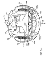
- FIG. 3A is a bottom view of the apparatus of FIG. 1 ;
- FIG. 3B is a front view of the apparatus of FIG. 1 with the bumper section removed;
- FIG. 4 is a perspective view of the apparatus of FIG. 1 with the handle section lifted;
- FIG. 5A is a cross section of the apparatus of FIG. 1 ;
- FIG. 5B is a front perspective view of the apparatus of FIG. 1 with the cover section removed;
- FIG. 6A is a cross sectional view of the nozzle and agitator unit of an embodiment of the present invention.
- FIG. 6B is a front view of the nozzle of FIG. 6A ;
- FIG. 7A is a bottom view of the rear portion of the apparatus.
- FIG. 7B is a cross-sectional view along line 7 B— 7 B of FIG. 7A ;
- FIG. 8 is a cross sectional view of an embodiment of a filtration unit of the apparatus and a portion of the apparatus;
- FIG. 9A is a perspective view of an embodiment of an impeller of the apparatus.
- FIG. 9B is a cross sectional view of the impeller of FIG. 9A ;
- FIGS. 9C and 9D are sectional views of the impeller of FIG. 9A ;
- FIG. 10A is a sectional view of a rotating member of the apparatus
- FIG. 10B is a cross-sectional view of the rotating member of FIG. 10A , taken along line 10 B— 10 B;
- FIG. 10C is a sectional view of a rotating member of the apparatus.
- FIG. 11 is a perspective view of an alternate embodiment of a rotating member, typically a brush, for the agitator unit of the present invention.
- FIGS. 12A and 12B are top and bottom views of an alternate nozzle and agitator unit for the present invention.
- FIG. 12C is a perspective view of an alternate agitator unit of the present invention.
- FIG. 13 is a view of the bumper section of the cover and the shock detection system; in accordance with an embodiment of the invention.
- FIG. 14 is a perspective view of the shock detection system of FIG. 13 ;
- FIG. 15 is a perspective view of a drive wheel
- FIG. 16 is a sectional view of the support wheel assembly
- FIG. 17 is a perspective view of the apparatus in operation using the leash
- FIG. 18 is a cross sectional view of the leash assembly
- FIG. 19 is a perspective view of the nozzle height adjustment system
- FIG. 20 is diagram of a door sensing system
- FIGS. 21A and 21B are diagrams of the door sensing system in operation with the apparatus of the invention.
- FIGS. 22A and 22B are diagrams of a stair sensing system in operation with the apparatus of the invention.
- FIG. 23 is a schematic diagram of the control system for the apparatus of the invention.
- FIGS. 24A and 24B are flow diagrams of an example navigation process used by the apparatus of the invention.
- FIG. 25 is a diagram of a system for confining the apparatus in accordance with the present invention.
- FIGS. 1 , 2 and 3 A show the apparatus 20 of the present invention in an exemplary configuration as a robotic vacuum cleaner.
- the apparatus 20 includes a cover 22 , formed of sections 100 , 101 , 104 and 106 (detailed below), with openings 24 a - 24 g in the bumper section (bumper) 104 .
- This control panel 25 includes various control knobs 26 a , indicators 26 b (Light Emitting Diodes (LED) or the like), 26 c (LED Display or the like), as well as a socket 27 for receiving a cord (plug end or the like) for charging the apparatus 20 in an electrical outlet or the like.
- a leash 28 also extends from this control panel 25 .
- the apparatus 20 includes sensors, that are part of sensing systems. Door detection sensors 30 a , 30 b in openings 31 a , 31 b are on or near the control panel 25 on the upper side of the apparatus 20 .
- the front side of the apparatus 20 includes contour sensors 34 , 35 ( FIG. 13 ) for lateral obstacle and wall detection, in openings 24 a and 24 b (FIG. 13 ), frontal obstacle detection sensors 36 a , 36 b in openings 24 c and 24 d , corner sensors 37 , in openings 24 e , a shelf detection sensor 38 in opening 24 f and remote control sensors 40 in upper opening 24 g and lateral openings 24 h (see also FIG. 13 ).
- These sensors 40 receive signals, typically infrared (IR) light signals, from a remote controller 46 or a coded transmitter 1300 , as shown in FIG. 25 and detailed below.
- IR infrared
- the apparatus 20 is formed of multiple systems, including a power system, drive (motion) system, navigation system, payload, or vacuuming system, bumper system, sensing (including obstacle detecting) systems, all coupled to a control system 1000 (FIG. 23 ), allowing for autonomous operation.
- This autonomous operation includes for example, vacuum cleaning or vacuuming, and other surface cleaning operations and movement therefore, by the apparatus 20 .
- the apparatus 20 also includes numerous other systems, shown and detailed below.
- the apparatus 20 is formed of a chassis 50 , having a base 52 and an extending portion 54 (FIG. 4 ), for supporting the components and systems (detailed herein).
- the chassis 50 rests on drive wheels 72 and a support wheel 74 .
- the drive wheels are typically limited to a single degree of freedom and are “active”, with each drive wheel 72 controlled by conventional axial drive mechanisms 73 (motors, etc.-FIG. 19 ).
- the support wheel 74 is “passive”, and typically has multiple degrees of freedom, as it is used for position, distance and orientation control of the apparatus 20 (shown in FIG. 16 and detailed below).
- This support wheel 74 is for example, a castor wheel, as detailed in FIG. 16 below.
- the drive wheels 72 are forward of the support wheel 74 , such that the apparatus 20 moves in the direction of the arrow 75 , this arrow indicating the “forward” direction. Accordingly, for description purposes of this document, the terms “forward” and “front” will refer to direction or orientation from the support wheel 74 to the drive wheels 72 , while the terms “rear” and “backward” will refer to the direction or orientation opposite of arrow 75 , the direction from the drive wheels 72 to the support wheel 74 (and associated electronics).
- Drive wheels 72 are driven independently of each other, so as to allow for steering (turning and directional changes), and define the steering system 1030 (FIG. 23 ).
- These drive wheels 72 (forming the steering system 1030 ) couple with the support wheel 74 , to form the drive system 1040 (FIG. 23 ).
- the steering system 1030 and drive system 1040 couple with the control system 1000 .
- the drive wheels 72 and support wheel 74 couple with the navigation system (processed through the microprocessor 1004 in FIG. 23 ).
- battery housings 85 (only one shown), envelope batteries 86 , typically 12 volt batteries, typically rechargeable, or other similar power source(s) that provide power to the apparatus 20 .
- the battery housings 85 include handles 87 , for ease in placement and removal of the batteries 86 (by a user 88 ) into and out of the apparatus 20 .
- the housings 86 typically at their bottom sides, include electrical plugs (not shown) for receipt in correspondingly configured sockets (not shown) on the chassis 50 , or vice versa, or other suitable paired electrical contacts.
- the sockets couple with power distribution electronics, to provide power to all components and systems of the apparatus 20 , as well as the control system 1000 .
- the batteries 86 and associated electronics and circuitry form the power system 1070 ( FIG. 23 ) for the apparatus 20 .
- a charging system 1074 ( FIG. 23 ) formed by a charging module (not shown), and associated circuitry.
- the charging module is electrically coupled to the batteries 86 .
- the charging module is also connected to the socket 27 or port, that can connect with an electrical line, that plugs into a conventional wall socket or the like, to provide electricity to the charging module and ultimately to the batteries.
- the cover 22 is typically formed in sections 100 , 101 , 104 , 106 .
- There are two underlying or main sections 100 , 101 mounted to the extending portion 54 of the chassis 50 in a fixed manner, overlapped in the from of the apparatus 20 by a bumper section (or bumper) 104 and in the rear of the apparatus 20 by a handle section 106 .
- the handle section 106 includes openings 108 , 118 where the filtration unit 148 ( FIG. 8 ) is viewable and a handle 106 a is formed from the handle opening 118 .
- the bumper section 104 is pivotally mounted on the apparatus 20 as it mounts (along its inner wall 110 ) to the bumper member 360 , as shown in FIGS. 13 and 14 and detailed below. This mounting suspends the bumper section 104 , allowing it to absorb impacts for the apparatus 20 .
- This bumper section 104 covers an arc of approximately 200 degrees (front and sides). Accordingly, this bumper section can handle frontal and lateral impacts to the apparatus 20 as well as impacts from points along the top of the apparatus 20 .
- This bumper section 104 forms part of the shock detection or bumper system 1082 ( FIGS. 13 , 14 and 23 ) and detailed below.
- the handle section 106 is pivotally mounted to the extending portion 54 of the chassis 50 .
- This section 106 includes an opening 118 , that when the apparatus 20 is in a use position, snap-fits into the main section 100 .
- the opening 118 is dimensioned such that the filtration unit 148 (FIG. 8 ), can be viewed.
- the lower portion of the section 106 is pivoted upward, whereby it is a handle 106 a , allowing the apparatus 20 to be carried by the user.
- the payload 130 is a vacuum cleaning system, and includes a nozzle 140 that connects to a tube 142 , through a duct 144 .
- the tube 142 extends into, and is typically part of, a filtration unit 148 (also in FIG. 3 ), that includes filter elements 150 and a particle collection area 152 .
- a conduit 154 connects the filtration unit 148 to an impeller chamber 156 , that houses an impeller 158 , that is rotated by a motor 160 .
- the impeller chamber 156 that houses the impeller 158 and motor 160 , is typically formed of shells 161 a , 161 b joined by mechanical fasteners, adhesives or other conventional arrangements, and a support member 162 (attached to the chassis 50 ), along a rim 162 r .
- the support member 162 includes a vent 163 , formed of bars 163 a , the vent 163 open to the ambient environment. This allows for air intake for suction (in the direction toward the impeller 158 , or downstream for purposes of this document).
- This arrangement forms a flow path for particles, that is considered to be indirect, since the filtration unit 148 is before the impeller 158 , in the particle flow path.
- An agitator unit 164 is at the base of the nozzle 140 .
- This agitator unit 164 includes a cover 164 a that typically includes a compartment 165 for accommodating rotating members 166 a , 166 b , and is positioned upstream of the nozzle 140 .
- the rotating members 166 a , 166 b are typically brushes or the like, whose rotation is controlled by a conventional rotator motor 308 .
- the agitator unit 164 may include rollers 168 or the like for contact with the surface or ground 183 , and may be mounted onto the chassis 50 in a manner, so as to contact the ground or surface 183 , providing resistance to it, and adjust to various levels in accordance with the contour of the ground or surface.
- the cover 164 a for example, at its front, begins at a height hh off of the ground 183 (for example, approximately 2 to 4 cm), exposing the rotating members 166 a , 166 b , so as to be an “open brush”.
- This “open brush” construction allows obstacles to be agitated by the rotating members 166 a , 166 b and suctioned away for enhanced cleaning and obstacle free movement of the apparatus 20 .
- These rotating members 166 a , 166 b in this construction can assist with drive movements.
- the nozzle 140 includes a neck 170 and a body 172 , that form an inner cavity 174 for particles (e.g., debris, etc.) to pass through.
- the neck 170 terminates in an opening 176 for attachment to the tube 142 of the filtration unit 148 .
- the other end extends to an outwardly tapered portion of the body 172 .
- the body 172 terminates in a lip 178 , that is typically rounded, with an opening 180 .
- This opening 180 includes a first, and typically upper edge 180 a , and is narrow at its middle 180 m or midsection and wide at the sides 180 s , as a result of the tapering (upward, away from the ground 183 ) of the lip 178 , so as to have uniform airflow into the nozzle opening 180 .
- the body 172 also includes sidewalls 172 a , that border a cut-out edge 182 .
- This cut out edge 182 defines a second, typically lower, edge of the opening 180 , and provides for ground clearance and greater maneuverability.
- the horizontal orientation of the nozzle body 172 coupled with the lip 178 extending beyond the cutout edge 182 , allows a flow cavity to be formed with the floor or surface 183 .
- This cavity is of a constant vertical aperture with respect to the opening 180 , as indicated by typically equal lengths 180 ′. This constant vertical aperture maintains acceleration of the airflow into the nozzle opening 180 and nozzle body 172 .
- the cavity coupled with the shape of the rotating members 166 a , 166 b creates a horizontal acceleration channel with horizontal air flow for particulates (debris, etc.) into the nozzle 140 .
- arms 184 extend laterally from the neck 170 and terminate in blocks 186 .
- the blocks 186 are mounted in boxes 188 , with receiving portions 189 , outer sidewalls 189 a and inner (cut-out) sidewalls 189 b .
- the blocks 186 are forced into the receiving portions 189 by biasing members (typically flexible), for example, springs 192 , that extend inside the blocks 186 and can be covered with an electrically insulation sheath 192 a tube or the like, and frictionally retain the blocks 186 in the boxes 188 .
- biasing members typically flexible
- springs 192 that extend inside the blocks 186 and can be covered with an electrically insulation sheath 192 a tube or the like, and frictionally retain the blocks 186 in the boxes 188 .
- the springs 192 can also be made of nonconducting material, for example, plastics or non-conducting metals (to avoid a short circuit between the plates 194 , 198 and the spring 192 , detailed below). This arrangement provides the blocks 186 with the ability for pivotal movement therein, ultimately allowing the nozzle 140 to pivot about the boxes 188 .
- the boxes 188 include electrical contacts 194 , 195 , typically metal sheets, plates, or the like, in communication with wiring 196 (from wire leads 196 a ) linked to the control system 1000 .
- the blocks 186 include a metal plate 198 at one end and a metal stub 199 (also FIG. 6B ) at the other end (along the arm 184 ), also connected by the wiring 196 .
- the plates 194 , 198 between the respective boxes 188 and the blocks 186 form “normally open” contacts, while the respective plates 195 of boxes 188 , and stubs 199 form “normally closed” contacts.
- This series of contacts and associated electronics defines a nozzle obstacle detection system 1080 (FIG. 23 ).
- the open contact (plates 194 , 198 ) and the closed contact (plate 195 and stub 199 ) are registered with the control system 1000 .
- the nozzle 140 upon its movement encounter a hard object, obstacle, or the dragging force become too great, the nozzle 140 will move. If the force is great enough, and movement of the nozzle 140 closes any of the normally open contacts, such that the plate 198 physically contacts the plate 194 , and/or opens the physical contact between the plate 195 and the stub 199 , a signal, typically indicating a closed or open circuit respectively (from the initially open and closed circuits, respectively), will be sent to the control system 1000 .
- control system 1000 With the requisite signal sent to the control system 1000 , the control system 1000 will signal the nozzle/rotating member height mechanism 560 , to raise the nozzle 140 (and the rotating members 166 a , 166 b attached thereto) over the obstacle. With the nozzle 140 and rotating members 166 having cleared the obstacle, travel of the apparatus 20 continues as normal. Alternately, the control system 1000 can be programmed to signal the drive system 1040 to cease operation immediately. (This is also true for other drive system stoppages throughout this document, that are not specifically detailed).
- the nozzle 140 is typically made of resilient materials, such as plastic (HDPE, PVC, Nylon, etc.) and is easily separable from both the base 52 of the chassis 50 and the agitator unit 164 .
- the nozzle 140 typically snaps into the base 54 with the agitator unit 164 snapping into the nozzle 140 , in a “tools free” manner.
- the agitator unit 164 snaps into the nozzle 140 as edges 204 of the agitator fit into slots 206 on the nozzle 140 ( FIGS. 6A , 6 B and 19 ).
- This engagement is held together by a resilient clip 208 on the agitator unit 164 having a spike (not shown) on its lower surface, the engages a correspondingly configured opening (not shown) on the nozzle 140 , holding the nozzle 140 and agitator unit 164 together.
- This snap-together arrangement allows for different nozzles to be placed onto the apparatus 20 . These different nozzles are designed for the specific type of particulate and surface that the apparatus 20 is to be operated on.
- the tube 142 is formed of a neck 222 and an outwardly tapered head portion 224 .
- the head portion 224 is typically of a diameter larger than the neck 222 , and is of a configuration to push particles around the filter element 150 (having pleats 150 a ), that is open on its lateral sides and above it. This results in air circulation along the pleats 150 a , that causes a self-cleaning effect, resulting in longer life for the filter element 150 . Pressure loss is minimized due to reduced blockage of the material forming the filter element 150 .
- This filtration unit 148 is a box-like article of a transparent material, such as plastic or the like, to allow for full bin sensing (detailed below) and inspection by viewing. It can be easily removed, by lifting, from the apparatus 20 , when the handle section 106 is lifted (as shown in FIG. 4 ). It typically separates into two pieces 230 , 231 (allowing for emptying of dirt held therein), that when placed together along edges 230 e , 231 e , lock in a frictional engagement. A fist piece 230 forms the bottom of the unit 148 , with its inner side serving as the particle collection area 152 or dirt cup.
- the preferred material for the filter 150 is a material having a permeability of approximately 100 CFM per square foot.
- a light transmitter 232 and a light receiver 233 that coupled with the requisite electronics, form a full bin sensing system 1020 (FIG. 23 ).
- the transmitter 232 and receiver 233 communicate with the filtration unit 148 through openings 232 a , 233 a in the extending portion 54 of the chassis 50 that borders the filtration unit 148 .
- the light transmitter 232 and light receiver, with associated electronics, couple to the control system 1000 .
- a “full bin” is sensed when dirt has accumulated in the filtration unit 148 to a point where light transmitted from the transmitter 232 can not be detected by the receiver 233 .
- a signal is then sent to from the control system 1000 , for example, to an indicator light 26 b indicating a full bin. (The filtration unit 148 can be removed and emptied as detailed above).
- FIGS. 9A-9D show the impeller 158 in detail.
- the impeller 158 is constructed to pull particulates downstream upon rotation by the motor 160 .
- the impeller 158 includes a central member 250 , typically conical in shape, with a bore 251 therein for accommodating a motor shaft 270 or the like and plates 254 , 255 , with two types of blades 256 , 258 therebetween.
- the upper plate 254 for example, has a radius of curvature RA of approximately 53 mm, while the conical portion 250 defining the lower plate 255 has a radius of curvature RB, for example, of approximately 39 mm.
- These blades 256 , 258 include short blades 256 , that typically extend from at least proximate the ends of the plates 254 , 255 to a point before the conical contour of the central member 250 , and longer twisted blades 258 , that extend from at least proximate the ends of the plates 254 , 255 to the conical contour of the central member 250 .
- the upper plate 254 includes an opening 262 to receive portions of the twisted blades 258 .
- Blades 256 , 258 are typically arranged in threes, with typically two arced (or short) blades 256 between each twisted blade 258 . There are typically five series of these three blade arrangements (two short blades and one twisted blade).
- Arced blades 256 are typically curved, so as to have exit angles ⁇ , typically 30 ⁇ 5 degrees, while twisted blades 258 typically are curved such that exit angles ⁇ are typically 30 ⁇ 5 degrees.
- These twisted blades include an upper blade twist angle ⁇ along the conical portion 250 of for example, approximately 10 degrees, and an input angle ⁇ of approximately 60 degrees, and a radius of curvature RX of for example, approximately 9 mm.
- the blades 256 , 258 are typically arced in the same direction, between the plates 254 , 255 .
- This configuration of blades 256 , 258 provides for high impeller efficiency of approximately 60%. (This efficiency defined by the output airflow divided by the motor input power).
- the impeller 158 is typically an integral, one piece structure, made of hard plastic, such as HDPE, PVC, Nylon. It is typically made by techniques such as injection molding or the like.
- the motor 160 is typically an 80 watt standard motor, or other similar motor. It includes a shaft 270 extending therefrom, to which the impeller 158 attaches. This motor 160 is electrically connected to the power system 1070 , and can operate at relatively low RPMs, for example here, the motor 160 may operate at approximately 7500 rpm. By operating at low RPMs, the motor operates at a low noise level and is energy efficient.
- the motor 160 is held on a motor support 272 (FIG. 5 A), that may be incorporated into the support member 162 .
- the agitator unit 164 includes rotating members 166 a , 166 b , typically brushes. These rotating members 166 a , 166 b are joined together by a pulley 300 , attached thereto, that is received in a belt 302 . The other end of the belt 302 is received by a shaft 306 of a motor (agitator motor) 308 , that rotates the shaft 306 , the motor 308 operated by the control system 1000 .
- a motor agitator motor
- Speed of the rotating members 166 a , 166 b can be changed according to surface type, detected by the method detailed below and signaled to the control system that signals the motor 308 , or manually entered into the control system 1000 by the user (typically via the remote controller 46 or through the user interface 25 ).
- the rotating members 166 a , 166 b or brush speed may be approximately 3000 RPM on carpet, and about 500 RPM on hard floors. The low RPM on hard floors is to eliminate particles from escaping under the nozzle 140 due to their high energy. This problem does not exist in carpets since there is not a gap between the nozzle 140 and the carpet.
- One method for defining or detecting the surface type is by measuring the load on the motor 308 that drives the rotating members 166 a , 166 b (brushes). This is due to a difference in load on the motor 308 between hard floors and medium to deep (e.g. medium to deep pile) carpets. These loads are signaled to the control system 1000 , that processes this information and signals the motor 308 to rotate the rotating members, at the above described speeds for hard floors and carpets respectively.
- the control system 1000 can detect that deep carpet is the surface over which the apparatus is traveling 20 , as detailed below. Based on this height detection, the control system can signal the motor 308 to the aforementioned speeds.
- the control system 1000 signals the motor 308 to rotate the rotating members 166 a , 166 b at the high speed, of approximately 3000 RPM.
- lower heights with respect to the surface 183 are indicative of hard floors, and thus, the control system 1000 signals the motor 308 to rotate the rotating members 166 a , 166 b at the low speed, of approximately 500 RPM.
- the motor 308 and rotating members 166 a , 166 b can also serve as a third surface detection mechanism.
- This system is particularly effective in detecting these low or low pile carpets. This is done in the microprocessor 1004 , that will analyze the load on the motor 308 for the rotating members 166 a , 166 b as a function of resistance provided by the surface being traversed.
- This detection mechanism involves a short shut down of the motor 308 , for example, approximately 0.5 seconds. Accordingly, rotation of the rotating members 166 a , 166 b ceases.
- the control system 1000 will signal the motor 308 to rotate the rotating members 166 a , 166 b , at a slow speed, typically approximately 500 RPM for hard floors, as detailed above.
- the surface being traversed is most likely a carpet, such as the low or low pile carpet, whereby the control system 1000 will signal the motor 308 to rotate the rotating members 166 a , 166 b , at a high speed, typically approximately 3000 RPM for carpets, as detailed above.
- both rotating members 166 a , 166 b will be described with respect to a single rotating member 166 a , that is exemplary of both rotating members 166 a , 166 b . Accordingly, all components of both rotating members 166 a , 166 b are the same and are numbered as such, except for grooves 314 a , 314 b , that are the same in construction, but are numbered differently to illustrate operational principles, as detailed below.
- the rotating members 166 a , 166 b both include a core 316 of diameter DC and a helical groove 314 a , 314 b , respectively, that extends into the core 316 .
- Diameter DC is typically large, for example, approximately 30 mm, resulting in a typically large perimeter of approximately 10 cm, so as not to allow fringes or other carpet or rug fragments to wrap around the core 316 .
- the groves 314 a , 314 b include a leading edge 318 , that is preferably straight and at least substantially parallel with respect to the vertical, and a trailing edge 319 that is preferably rounded. (The leading edge 318 and trailing edge 319 of the grove 314 a , 314 b are referred to as such, in accordance with the preferred rotational direction of the rotating members 166 a , 166 b , indicated by arrow RM.)
- Bristles 320 anchored into the core 316 of the rotating member 166 a , 166 b , by conventional fastening techniques, extend from the core 316 , through the groove 314 a , 314 b to slightly beyond the outer surface 322 of the rotating member 166 a , 166 b .
- the bristles 320 can bend, so as not to inhibit torque on the rotating members 166 a , 166 b .
- These bristles 320 are typically made of nylon or the like.
- the rotating members 166 a , 166 b are connected to the pulley 300 at an orientation where the respective grooves 314 a , 314 b form a “V”, such that these grooves 314 a , 314 b spiral outward from the center of the apparatus 20 .
- This orientation of the grooves 314 a , 314 b coupled with their construction, the diameter of the core 316 , bristle 320 arrangement in the grooves 314 a , 314 b and length, moves dirt toward the center or inward into the nozzle 140 .
- These rotating members 166 a , 166 b are also detachable, and can be replaced with other suitable brushes or the like.
- FIG. 11 there is an alternate rotating member 166 ′, typically a brush with a core 312 ′, that is attached to the agitator unit 164 as detailed above.
- the rotating member 166 ′ is similar in all aspects to the rotating members 166 a , 166 b , except where indicated.
- the rotating member 166 ′ is formed of resilient members 320 ′, for example, of hard plastic, rubber or the like, embedded therein or attached thereto. Upon rotation of the brush, the rotating members 320 ′ strike the surface with a force sufficient to agitate or bring up particulates. These members 320 ′ can also bend, so as to keep torque on the rotating member 166 ′ at suitable levels for proper operation.
- FIGS. 12A and 12B detail alternate embodiments of the nozzle 140 ′ and for the agitator unit 164 ′. All components are the same as those in the nozzle 140 and agitator unit 164 detailed above, except where indicated.
- the nozzle 140 ′ there are protrusions 328 at the nozzle opening 180 , to make airflow uniform at the nozzle opening 180 .
- the rotating members have been replaced by a clapping unit 330 .
- the clapping unit 330 attaches to the nozzle 140 by a plate 331 , via screw mechanisms 331 a or the like.
- This clapping unit 330 includes the pulley 300 attached to a rod 332 , on which are connected wheels 334 and cams 335 with lips 335 a , that upon rotation of the rod, move clips 338 , by lifting their flanges 338 a , up and down, typically at different times (although all at the same time is also suitable), to create agitation of particulates for suction.
- FIG. 12C details another alternate embodiment agitator unit 164 ′′.
- there are two motors 340 a , 340 b that typically rotate cams 342 a , 342 b in opposite directions, as indicated by the arrows 343 a , 343 b .
- Non-motorized cams 344 mounted to the apparatus 20 support belts 345 that include bristles 320 ′′.
- the belts 345 and bristles 320 ′′ travel in a direction substantially perpendicular to the direction of travel of the apparatus 20 (indicated by arrow 75 ). This substantially perpendicular direction of travel is sufficient to create the requisite agitation of particulates for suction as detailed above.
- FIGS. 13 and 14 (in FIG. 14 , the support member 162 is partially cut away) detail the shock detection system 1082 ( FIG. 23 ) for the apparatus 20 .
- This system includes bumper member 360 , having rods 362 received in oppositely disposed lateral supports 364 , that abut lateral segments 162 a , typically having an inverted “L” shaped contour, on the support member 162 .
- the rods 362 are hooked to springs 366 , that in turn are hooked to the vent bars 163 a of the support member 162 .
- the springs 366 pull the rods 362 upward, such that the lateral supports 364 engage the lateral segments 162 a .
- This attachment provides the ends of the lateral supports 364 with pivotal movement at pivot points 365 a , 365 b , from the lateral segments 162 a .
- This pivotal movement may occur upon frontal or top impacts to the apparatus 20 .
- the lateral supports 364 include oppositely disposed protrusions 370 that are received in correspondingly configured tracks 372 on the inner wall 110 of the bumper section 104 (only one shown).
- the positioning of the bumper member 360 in the apparatus 20 is such that shock detection is provided along an arc of approximately 200 degrees.
- the bumper section 104 is supported at its center of gravity, inhibiting tilting torque from developing during acceleration and deceleration of the apparatus 20 .
- the linear force on the center of gravity during acceleration is balanced by the spring 366 force, where the front mounting eliminates any movement during deceleration.
- the bumper section 104 and bumper member 360 are connected such that a static force of approximately 0.26 kilograms (Kg) on the upper and lower ends of the bumper section 104 and increasing to a static force of 1.2 Kg at the center will activate a signal to the control system 1000 that the bumper section 104 has contacted an obstacle and for example, the drive system 1040 must be signaled to cease motion, by the control system 1000 .
- the drive system 1040 will stop motion, such that the apparatus 20 has traveled not more than approximately 15 cm from the time of impact with the obstacle.
- the rods 362 are connected by a central member 374 , that rests between arms 376 from a spring 378 . These arms 376 , each rest in grooves 380 , within a guide 382 , and while movable, provide a resistive force against lateral movement of the central member 374 , in the case of side impacts on the apparatus 20 .
- Metal clips or plates extend along the inner sides of the lateral supports 364 , and contact metal members (not shown) at the pivot points 365 a , 365 b on the lateral segments 162 a , to form electrical contacts.
- Arms 376 also of a metallic material, contact a metal band 388 on a member 390 . rearward of the guide 382 . In the case of a front impact of sufficient force (overcoming that of the springs 366 ), the bumper member 360 will be moved pivotally.
- electrical leads 392 throughout this member 360 to which wires or the like are connected for coupling with the electronics of the control system.
- a signal will then be sent to the control system 1000 , that will then, for example, signal the drive system 1040 to cease motion immediately.
- the bumper member 360 will move laterally, such that this movement causes at least one of the arms 376 to move out of contact with the band 388 .
- This will also cause a signal to be sent to the control system 1000 , that will then, for example, signal the drive system 1040 to cease motion.
- these pivotal and lateral movements are caused by contact to the bumper section 104 at the front of the apparatus 20 .
- the bumper member 360 is configured for example, such that movements of approximately 2 mm or greater to the bumper section 104 or forces as detailed above, will cause these pivotal or lateral movements, to occur, whereby at least one requisite electrical contact is made or broken. This change in electrical contact will result in a signal being sent to the control system 1000 , that will signal the drive system 1040 to stop, ceasing motion of the apparatus 20 (as detailed above). Motion ceases within the depression limits of the bumper member 104 , that is typically not more than 20 mm.
- FIG. 15 shows a drive wheel 72 (representative of both drive wheels), that typically includes a tread portion 72 t formed of lateral protrusions 72 a , defining outer rows, with central “+” shaped protrusions 72 b , defining an inner row.
- This provides the drive wheel 72 with increased traction, to minimize slippage along various surfaces, for example, hard floors and carpets. This allows for precise movement of the apparatus 20 .
- the drive wheel 72 at this treaded portion is typically made of a soft rubber or the like.
- the protrusions 72 b of the inner row are “+” shaped so as to be reinforced laterally, to establish a central point for turning.
- the protrusions 72 a of the outer rows are flexible laterally, to smooth the drive path and are flexible laterally allowing for turning with minimal movement of the turning center.
- the gaps between protrusions 72 a of the outer rows improve climbing on carpets, should the carpet be approached from an angle.
- FIG. 16 shows the support wheel 74 in an assembly that with associated electronics forms a portion of the drive system 1040 ( FIG. 23 ) that couples to the control system 1000 .
- the support wheel 74 is, for example, a castor wheel, typically formed of two shells 400 a , 400 b (FIG. 2 ), so as to have a hollow inner chamber 402 .
- a band 403 (FIG. 2 ), made of rubber or the like, placed around the support wheel 74 .
- magnets 404 or other metal objects detectable by magnets or the like.
- the shells 400 a , 400 b also include aligned bores 408 for receiving the axial portion 410 of a movement arm 412 (the other portion of the movement arm 412 being the main portion 414 ).
- the support wheel 74 tracks odometry and angles of travel, to signal the control system 1000 for determining direction and orientation of the apparatus 20 .
- the movement arm 412 at its main portion 414 is rotatably mounted within a sensor unit 416 .
- This sensor unit 416 includes several, typically three, magnetic field sensors 418 , such as hall effect sensors, located over a circle around the arm 412 . These sensors 418 send signals to the control system 1000 .
- the positions of the magnets 404 in the wheel inner chamber 402 are utilized by the control system 1000 , in an odometer function, to determine total displacement.
- the control system 1000 By monitoring the signal obtained from the magnetic field sensors 418 , both the travel distance and the orientation of the castor wheel 74 can be determined (the distance is obtained by counting the number of pulses induced by the traveling magnets 404 where the angle is calculated by comparing the strength of signal between the magnetic field sensors 418 ).
- control system 1000 can adjust the steering 1030 and drive 1040 systems accordingly, to properly position the apparatus 20 .
- the control system 1000 with this information can also control the navigation system accordingly.
- the leash 28 is a wire 508 or the like, and includes a balled end 510 and a coiled end 512 , typically wrapped around a spring biased roller 514 in the body of the apparatus 20 .
- the wire 508 extends through a mechanical member 520 , intermediate its ends.
- the mechanical member 520 includes a body 522 , and oppositely disposed ring members 524 , 525 with hemispherical protrusions 524 a , 525 a resting in each other in alignment. Ring members 524 , 525 also include a tubular guide 524 b , 525 b . Upper ring member 525 is held in place by a spring 528 , that is held in place by the body cover 530 and the neck 525 c of the ring member 525 . This spring 528 allows for movement of the upper ring member 525 when the leash 28 (wire 508 ) is pulled.
- a sensor(s) 540 coupled to the control system 1000 , connects to the ring members 524 , 525 and detects which protrusions 524 a , 525 a , were temporarily pulled out of alignment, and signals this back to the control system 1000 .
- the control system 1000 recognizes this direction, and powers the drive wheels 72 accordingly, with the direction and orientation of the apparatus determined by the support wheel 74 and its sensors reporting to the control system 1000 .
- FIGS. 3B and 19 there is a nozzle height adjusting system 560 (FIG. 23 ), coupled to the control system 1000 , that raises and lowers the nozzle 140 , in response to the surface, and in some cases, obstacles detected.
- the nozzle 140 includes a bracket 561 with an opening 562 therein. This opening 562 is engaged by a rod 564 attached to an adjustment mechanism 566 , and with associated electronics, is coupled to the control system 1000 .
- the nozzle 140 is spring mounted, and can be pushed upward, to contact a metal or magnetic portion 570 of a member 572 within a spring 573 .
- the end of the metal member 572 is detected by a magnet (magnetic sensor) 580 , for example, a hall effect sensor, that senses a position change for the member 572 , and will indicate this change, via signals or the like to the control system 1000 , that will signal the adjustment mechanism 566 , typically including a motor 566 a .
- This motor 566 a will drive an eccentric member 566 b , that translates rotation to vertical movement by moving the rod 564 , and therefore the nozzle 140 up to the proper position.
- the nozzle 140 will move down provided there is open space between the rotating members 166 a , 166 b , i.e., brushes, and the surface, as detailed below).
- the nozzle height adjustment system 560 typically functions to set only the minimum height for the nozzle 140 and rotating members 166 a , 166 b (i.e., brushes) (since the nozzle 140 is attached to the rotating members 166 a , 166 b , they are treated as a single unitnozzle/rotating members, for purposes of this example description). Accordingly, it can adjust the nozzle 140 /rotating members 166 a , 166 b , for higher surfaces automatically, since the nozzle 140 /rotating members 166 a , 166 b can travel freely upward.
- rotating members 166 a , 166 b i.e., brushes
- the minimum height is required to keep the nozzle 140 /rotating members 166 a , 166 b (i.e., brushes) at a desired height, and therefore reducing the load on the nozzle/rotating members, as induced by the carpet.
- the rollers 168 maintain the nozzle 140 /brushes 166 a , 166 b at the correct height.
- the measurement of height for the rotating members 166 a , 166 b is also suitable for determining surface types, in particular, carpets versus hard floors or other surfaces. This can be achieved because the brushes 166 a , 166 b and nozzle 140 have a degree of freedom in the upward direction, and therefore, can follow the level or contour of the surface on which they are riding. For example, in carpets, the rollers 168 sink slightly, the brush height in relation to the rollers 168 will be different from this height on a hard floor, and thus the surface type can be determined.
- All of these sensors are electrically coupled to the control system 1000 , that in turn signals the drive system 1040 and drive wheels 72 to operate in various modes, depending upon the obstacle or opening detected.
- door detection sensor 30 a is typically formed of two infra-red (infrared or IR) transmitters 600 a , 600 b , while the other door detection sensor 30 b is typically formed of an IR receiver(s) 602 .
- the transmitters 600 a , 600 b are positioned at an angle ⁇ , with respect to each other, that is, for example, approximately 20-30 degrees, and at a distance zz from each other, for example, approximately 10 mm.
- One transmitter, here, transmitter 600 a , and the receiver 602 are typically also tilted approximately 5 degrees (into the plane of the paper). This tilting limits potentially unwanted reflections from horizontal highly reflective surfaces such as metal door frames, mirrors, lights, reflectors, etc., since most of the light energy in these cases will be projected 10 degrees forward rather than returning to the receiver 602 .
- Door or boundary detectors include retro-reflectors 606 (reflectors that reflect light back at approximately the same angle received), typically sticker-like, of which one or more can be placed on the floor proximate the door 608 and/or within the doorjamb itself. Should a floor or wall boundary be desired, the retro-reflector 606 may be placed on the floor or wall, and similarly, the retro-reflector 606 may be placed on the ceiling to define the desired wall or floor boundary.
- retro-reflectors 606 reflectors that reflect light back at approximately the same angle received
- typically sticker-like of which one or more can be placed on the floor proximate the door 608 and/or within the doorjamb itself.
- the retro-reflector 606 may be placed on the floor or wall, and similarly, the retro-reflector 606 may be placed on the ceiling to define the desired wall or floor boundary.
- the transmitters 600 a , 600 b by being arranged at this angle ⁇ , can detect the desired doors, and entryways for these doors, while distinguishing them from other locations, such as under tables, counters or the like.
- the transmitters 600 a , 600 b emit light beams 609 a , 609 b (illustrated in FIGS. 21A and 21B for description purposes).
- the range for the receiver 600 is also represented by a beam 610 (also, only for description purposes).
- the receiver 602 will detect a reflection of a beam from the corresponding transmitter 600 a (illustrated by beams 609 a , 610 ) off of the retro-reflector 606 , while the receiver 602 will not detect a reflection from the second transmitter 600 b.
- the requisite signals based on whether or not light from zero, one or both sensors (transmitters) 600 a , 600 b was received, (by the receiver 602 ), are sent to the control system 1000 .
- This control system 1000 will signal the drive system 1040 ( FIG. 23 ) ceasing motion of the apparatus 20 or changing direction of the apparatus 20 , as per the determined travel (cleaning) pattern, as detailed below.
- transmitters, receivers and reflector(s) can be replaced by any combination of transmitters, receivers and reflectors, provided they function as detailed above.
- Contour sensors 34 , 35 are typically mounted laterally, at the sides of the apparatus 20 at upper and lower positions. These sensors 34 , 35 are used for detecting walls, furniture and other laterally positioned obstacles. These sensors 34 , 35 , are typically formed of an ultrasonic transmitter and an ultrasonic receiver. These contour sensors are in communication with the control system 1000 , and should a wall, furniture or other lateral obstacle be detected, the control system 1000 will signal the drive system 1040 ceasing motion of the apparatus 20 , as detailed above.
- Obstacle sensors 36 a , 36 b , 37 for detecting obstacles, such as furniture, walls, or other obstacles, are typically arranged so as to cover the front of the apparatus 20 .
- front obstacle sensors 36 a , 36 b are disposed high and low on the apparatus 20 with respect to each other and in a substantially parallelogram-shaped pattern with respect to each other.
- the corner sensors 37 are in a relationship where their signals cross each other. For example, this crossing is typically at an approximately 90 degree orientation.
- These obstacle sensors 36 a , 36 b , 37 are typically ultrasonic transceivers, but other equivalent sensors are also permissible.
- These obstacle sensors 36 a , 36 b , 37 are in communication with the control system 1000 , and should an obstacle be detected, will send a signal to the control system 1000 accordingly, that will typically cease motion of the drive system 1040 , as detailed above.
- the obstacle sensors may be units, such as 40 Khz ultrasonic transducer, Part No. 400PT160, from Prowave.
- These ultrasonic sensors 34 , 35 36 a , 36 b , 37 define an array, and function as proximity sensors (of a proximity sensing system), that when coupled with the control system 1000 , can provide a low resolution image of the obstacle path in front of the apparatus 20 .
- a sensor 38 typically for horizontal object, for example, shelf, detection.
- This sensor 38 typically includes a transmitter portion and a receiver portion, angularly upward (for example an angle of approximately 35 degrees with respect to the horizontal).
- This sensor 38 is typically a Position Sensing Diode (PSD), formed from infrared transmitting and receiving components, and for example, may be a Sharp® infra-red sensor unit, Part No. GP 2D12 14 from Sharp Electronics, Japan.
- PSD Position Sensing Diode
- this sensor 38 provides the requisite horizontal object detection. It also functions in combination with obstacle sensors 36 a , 36 b , 37 (and the control system 1000 ) to create a local map. Should a low obstacle be detected, a signal will be sent to the control system 1000 , that will signal the drive system 1040 , ceasing motion of the apparatus 20 , as detailed above.
- sensors 620 (only one shown) (ranges of each sensor illustrated by beam projections 621 ), coupled to the control system 1000 , are for detecting height variances, typically associated with stair detection. These sensors 620 are typically attached on opposite sides of the extending portion 54 , that extends from the chassis 50 . These sensors 620 are typically position sensing diodes (as detailed above). For example, the variance subject to detection would typically occur with stairs, that is about 3 cm from the surface on which the apparatus 20 rides. With this variance detected, the sensors 620 will signal the control system 1000 , whereby the drive system 1040 will cease motion of the apparatus 20 , as it was too close to stairs or other downward decline in the surface.
- FIG. 23 There is also a full bin sensor system 1020 (FIG. 23 ), formed of a transmitter 232 and receiver 233 positioned proximate to the filtration unit 148 (detailed above). This full bin sensor system 1020 is coupled to the control system 1000 .
- the remote control sensors 40 are typically infra-red (infrared or IR) sensors. They are coupled to the control system 1000 , that accepts commands from the remote controller 46 , transmitted in the form of infra-red light. They are positioned frontally and laterally in the apparatus 20 ( FIGS. 1 and 13 ) to receive signals from the remote controller 46 regardless of the position of the apparatus 20 .
- IR infra-red
- the remote controller 46 is typically an infra-red (infrared or IR) remote controller (as detailed above) or the like. This remote controller 46 can signal directly to the control system 1000 (as the remote control sensor 40 is coupled to the control system 1000 ) various commands, such as ON/OFF, various travel modes, various cleaning modes and patterns, strengths of cleaning, speed of the apparatus, etc.
- IR infra-red
- control system 1000 can be programmed to function in a cleaning mode and pattern, where upon being signaled, typically by the remote controller 46 , the apparatus 20 , will “spot clean.” This involves small precise movements concentrated around a small area for cleaning this small area. This concentrated cleaning may involve high power suction by the apparatus 20 as it travels in small, typically overlapping, circles in a highly repetitious manner around this small area.
- control system 1000 can be programmed to perform a travel mode, where once signaled, typically by the remote controller 46 , and the signal is received by one of the remote control sensors 40 , the apparatus 20 navigates its way to a point proximate the remote controller 46 , from its present location.
- This is known as the “call me” function, and typically is a dedicated key on the remote controller 46 , but could also be a code or the like.
- Navigation and movement to the point proximate the remote controller 46 can be wholly or partially in accordance with the sensors and associated systems and portions of the exemplary navigation program, detailed below (in blocks 1201 - 1244 of FIG. 24 ).
- Navigation back to the point proximate to the remote controller can also be partially or wholly by a beam riding mechanism, where the beam from the remote controller 46 is tracked by the control system 1000 and the apparatus 20 is rotated and maneuvered to the point proximate the remote controller 46 .
- FIG. 23 is a schematic diagram of the control system 1000 of the apparatus 20 .
- the control system 1000 includes a main processing board 1002 , that includes processing circuitry and other related circuitry, and a processor, such as a microprocessor (MP) 1004 , that for example, serves as the central processing unit (CPU), for this main processing board 1002 .
- the microprocessor 1004 is preprogrammed as well as having functionalities for receiving programs (typically entered through the remote controller 46 by the user). These programs may be for automatic or manual operation of the apparatus, or combinations thereof.
- the apparatus 20 can also include storage media (not shown), coupled to the control system 1000 or various components thereof. This storage media stores data, such as scanning patterns for cleaning, sound samples, mapping functions, travel modes, etc.
- This microprocessor 1004 can be, for example, a Hitachi H8S2350 processor.
- the navigation system and remote control command processing are through the microprocessor 1004 . There functions, as well as others are directly integrated into the microprocessor 1004 .
- the control system 1000 and in particular the main processing board 1002 and accordingly, the microprocessor 1004 , are coupled to various components and systems, as detailed below. All below-listed components and systems include the requisite associated electronics and electronic couplings in order for proper operation with the main processing board 1002 and microprocessor 1004 .
- This control system 1000 controls power distribution to all systems and components as well as all operations thereof, for example, speeds, on/off, adjustments, positioning, etc. All components mentioned below, controlled by the control system 1000 include the requisite electronics, circuitry, couplings, etc., so as to define systems controlled by the main processing board 1002 and microprocessor 1004 of the control system 1000 .
- the user interface 25 is electronically coupled (with the requisite associated electronics) to the main processing board 1002 , and accordingly, the microprocessor 1004 ).
- This main processing board 1002 (and accordingly the microprocessor 1004 ) is also coupled to the door detection sensors 30 a , 30 b , contour sensors 34 , 35 , obstacle sensors, 36 a , 36 b , 37 , Infra-red sensors, e.g., the sensor 38 and remote control sensor 40 , the stair detection sensors 620 , and the full bin sensing system 1020 .
- the main board 1002 and microprocessor 1004 are also coupled to the steering system 1030 , that includes left 1032 a and right 1032 b drive motors and corresponding left 1034 a and right 1034 b odometers, associated with the respective drive wheels 72 .
- This drive system 1040 also includes the angle sensing system 1042 and odometry system 1044 of the guide wheel 74 .
- the navigation system also couples to these steering 1030 and drive 1040 systems through the main board 1002 .
- the main board 1002 and microprocessor 1004 also couple to a power system 1070 , that include the batteries 86 , and associated electronics, as well as the charging system 1074 .
- the main board 1002 and microprocessor 1004 also control power to and thus, speed of the impeller motor 160 and agitator motor 308 .
- There is also a coupling of the main board 1002 /microprocessor 1004 with the “normally open” and “normally closed” electrical contacts defining the nozzle obstacle sensor system 1080 (detailed above).
- the main board 1002 /microprocessor 1004 with the nozzle height adjustment system 560 , including the nozzle height adjustment motor 566 and a nozzle height sensor 582 , as well as the shock detection system 1082 , in particular, the sensors associated therewith (detailed above).
- the main board 1002 /microprocessor 1004 can also couple to additional systems 1090 , that include for example, supplemental proximity sensing systems, supplemental navigation systems, etc.
- FIG. 24A is a flow diagram indicating an example process of navigation and scanning for movement of the apparatus 20 for vacuum cleaning or the like.
- this process 1200 can be implemented by the microprocessor 1004 . It is typically preprogrammed therein and coupled with the control system 1000 and main board 1002 will be performed by the apparatus 20 .
- the process 1200 begins at a START, block 1201 , typically by activating the apparatus.
- the control system 1000 via the microprocessor 1004 selects a footprint (path or scanning pattern) for the movement of the apparatus 20 , at block 1202 .
- the system always includes a default footprint. Alternately, this footprint can be selected by the user, with the signals corresponding to the desired footprint entered into the control system.
- the control system 1000 via the microprocessor 1004 , then signals the drive system 1040 .
- This signal causes operation of the drive system 1040 , where the apparatus 20 scans the immediate area in accordance with the selected footprint, at block 1204 .
- the “footprint” for scanning is the pattern of movement of the apparatus. This pattern is typically triangular, and in particular in isocelises triangles. It can also be rectangular in linear movements. Scanning patterns are typically designed so as to be substantially free of repetition. For example, scanning patterns may be as disclosed in commonly owned U.S. Pat. No. 6,255,793 and PCT Patent Application PCT/IL99/00248 (WO 99/59042), both of these documents incorporated by reference in their entirety herein.
- the area being scanned is then monitored, at block 1206 . Scanning continues until it is detected and signaled to the control system 1000 , that the apparatus can no longer move laterally for scanning, at block 1208 . At block 1208 , the scanning is ended, or the “end of sweep” has been determined.
- an opening, suitable in size for the apparatus 20 to enter was detected during scanning (typically by contour sensors 34 , 35 , as shown in FIGS. 1 and 13 ), at block 1210 . If an opening of suitable size was not detected during the scan, it is then determined if the apparatus 20 has scanned for a predetermined time, area and or distance, or combination thereof, at block 1220 . This is in accordance with predetermined policies, typically preprogrammed into the microprocessor 1004 .
- the scan direction is changed, at block 1222 .
- the process then returns to block 1202 .
- Changing of the scanning direction for example, can involve a turning movement of approximately 45 degrees by the apparatus 20 , with scanning typically employing the same footprint, as was determined at block 1202 .
- Other turning angles are also permissible, and can be programmed or entered into the control system 1000 , for example, through the remote controller 46 .
- a contour movement to the opening is signaled at block 1232 .
- This contour movement involves the apparatus 20 moving along the sides or periphery (typically defined by the walls of the room or area), or proximate thereto (collectively, the “contour”), of the scanned area to look for the opening, as detected by the contour sensors 34 , 35 (detailed above). Initially, if necessary, prior to the contour movement (based on the position of the apparatus 20 upon reaching the end of sweep), the apparatus 20 moves to a point along or proximate the sides or periphery from where the contour movement (to the opening) will begin.
- the apparatus 20 is signaled (from the control system 1000 ) to enter and move through the opening, at block 1234 , by sensing the contour (by contour sensors 34 , 35 ) and following it to the next area to be cleaned (scanned). It is then determined if the opening is blocked, at block 1236 . If the opening is not blocked, the process returns to block 1204 .
- the apparatus 20 is driven to return to the beginning of the opening at block 1238 , where the scanning direction is changed, as the process returns to block 1222 . With the scanning direction changed, the process returns to block 1202 .
- a contour movement is signaled, at block 1242 .
- This contour movement involves the apparatus 20 moving along the sides, periphery or proximate thereto, of the scanned area (typically defined by the walls of the room or area) to look for an opening, suitable for passage of the apparatus therethrough, at block 1244 .
- the apparatus 20 is signaled (from the control system 1000 ) to enter and move through the opening, at block 1234 .
- the process continues from this point (block 1234 ) as detailed above.
- contour movements in blocks 1232 and 1242 can be replaced with point to point navigation, as detailed above.
- the determination as to whether to make a contour movement or point to point navigation can be programmed into the microprocessor 1004 .
- the above process 1200 repeats for as long as necessary, typically until a time out, power outage or deactivation (turned OFF) by the user.
- FIG. 24B is a flow diagram indicating another example process of navigation and scanning for movement of the apparatus 20 for vacuum cleaning or the like.
- this process 1250 can be implemented by the microprocessor 1004 . It is typically preprogrammed therein and coupled with the control system 1000 and main board 1002 will be performed by the apparatus 20 .
- blocks 1201 ′, 1202 ′, 1204 ′, 1206 ′ and 1208 ′ are similar to corresponding blocks 1201 , 1202 , 1204 , 1206 and 1208 , that have been described above, those descriptions applicable here.
- block 1208 ′ As lateral advancement for the apparatus 20 is no longer possible, here, the apparatus 20 having reached the end of sweep, the process moves to block 1252 .
- block 1252 there is performed a contour movement in accordance with the coutour movements detailed above. Additionally, if necessary, prior to the contour movement (based on the position of the apparatus 20 upon reaching the end of sweep), the apparatus 20 moves to a point along or proximate the sides or periphery from where the contour movement will begin.
- This contour movement can be for a predetermined or preset distance.
- the process returns to block 1201 ′, whereby scanning of an area or portion thereof begins again.
- the process repeats for as long as necessary, typically until a time out, power outage or deactivation (turned OFF) by the user.
- the microprocessor 1004 is also programmed for all of the above detailed cleaning and travel modes and combinations thereof.
- the microprocessor 1004 operates in conjunction with the main board 1002 and control system 1000 , for all of these additional cleaning and travel modes.
- the microprocessor 1004 is also programmed to determine distances traveled for odometers of the drive 72 and support 74 wheels.
- FIG. 25 there is detailed another function of the invention.
- the apparatus 20 can be confined to specific areas, by the placement of one or more coded transmitters 1300 at various locations in a room.
- the transmitter 1300 functions as a “virtual” wall.
- coded transmitter 1300 is positioned such that its “IN” beam 1308 is on the QQ side of the room 1302 , while the “OUT” beam 1309 is on the RR side of the room 1302 . Both of these beams 1308 and 1309 are typically of IR light so as to be detectable by the sensors 40 . Once detected, signals are sent from the sensors 40 to the control unit 1000 , that processes these signals and controls the drive system 1040 to maintain the apparatus 20 in the proper portion of the room, here portion QQ.
Abstract
Description
D=[K 1 ·d][ΣL i/max{L i }]+[K 2·max{L i}]
where,
-
- Li is the series L1 to Ln, and L1 to Ln are the lengths of each straight line portion of the scanned pattern;
- K1 and K2 can be, for example, K1=0.8, K2=1, where Li are measured in meters; and
- d is the diameter of the apparatus, for
example apparatus 20, expressed in meters.
Claims (39)
D=[K 1 ·d][ΣL i/max{L i }]+[K 2·max{L i}]
D=[K 1 ·d][ΣL i/max{L i }]+[K 2·max{L i}]
Priority Applications (7)
| Application Number | Priority Date | Filing Date | Title |
|---|---|---|---|
| PCT/IL2002/000788 WO2003026474A2 (en) | 2001-09-26 | 2002-09-25 | Robotic vacuum cleaner |
| EP02775174.2A EP1441632B1 (en) | 2001-09-26 | 2002-09-25 | Robotic vacuum cleaner |
| AU2002341358A AU2002341358A1 (en) | 2001-09-26 | 2002-09-25 | Robotic vacuum cleaner |
| US10/360,092 US7079923B2 (en) | 2001-09-26 | 2003-02-07 | Robotic vacuum cleaner |
| US11/487,850 US7444206B2 (en) | 2001-09-26 | 2006-07-17 | Robotic vacuum cleaner |
| US12/181,869 US7769490B2 (en) | 2001-09-26 | 2008-07-29 | Robotic vacuum cleaner |
| US12/846,194 US8311674B2 (en) | 2001-09-26 | 2010-07-29 | Robotic vacuum cleaner |
Applications Claiming Priority (2)
| Application Number | Priority Date | Filing Date | Title |
|---|---|---|---|
| IL14568001A IL145680A0 (en) | 2001-09-26 | 2001-09-26 | Robotic vacuum cleaner |
| IL145680 | 2001-09-26 |
Related Child Applications (1)
| Application Number | Title | Priority Date | Filing Date |
|---|---|---|---|
| US10/360,092 Continuation US7079923B2 (en) | 2001-09-26 | 2003-02-07 | Robotic vacuum cleaner |
Publications (2)
| Publication Number | Publication Date |
|---|---|
| US20030060928A1 US20030060928A1 (en) | 2003-03-27 |
| US7167775B2 true US7167775B2 (en) | 2007-01-23 |
Family
ID=11075815
Family Applications (1)
| Application Number | Title | Priority Date | Filing Date |
|---|---|---|---|
| US10/007,103 Expired - Fee Related US7167775B2 (en) | 2001-09-26 | 2001-12-04 | Robotic vacuum cleaner |
Country Status (2)
| Country | Link |
|---|---|
| US (1) | US7167775B2 (en) |
| IL (1) | IL145680A0 (en) |
Cited By (85)
| Publication number | Priority date | Publication date | Assignee | Title |
|---|---|---|---|---|
| US20040236468A1 (en) * | 2003-03-14 | 2004-11-25 | Taylor Charles E. | Robot vacuum with remote control mode |
| US20050021181A1 (en) * | 2003-07-24 | 2005-01-27 | Samsung Gwangju Electronics Co., Ltd. | Robot cleaner |
| US20050137749A1 (en) * | 2003-12-22 | 2005-06-23 | Lg Electronics Inc. | Robot cleaner and operating method thereof |
| US20060020369A1 (en) * | 2004-03-11 | 2006-01-26 | Taylor Charles E | Robot vacuum cleaner |
| US20060085095A1 (en) * | 2003-09-19 | 2006-04-20 | Royal Appliance Mfg. Co. | Sensors and associated methods for controlling a vacuum cleaner |
| US20060087273A1 (en) * | 2004-10-27 | 2006-04-27 | Samsung Gwangju Electronics Co., Ltd | Robot cleaner system and a method for returning to external recharging apparatus |
| US20060184293A1 (en) * | 2005-02-18 | 2006-08-17 | Stephanos Konandreas | Autonomous surface cleaning robot for wet cleaning |
| US20060190132A1 (en) * | 2005-02-18 | 2006-08-24 | Christopher John Morse | Autonomous surface cleaning robot for dry cleaning |
| US20060190134A1 (en) * | 2005-02-18 | 2006-08-24 | Irobot Corporation | Autonomous surface cleaning robot for wet and dry cleaning |
| US20070016328A1 (en) * | 2005-02-18 | 2007-01-18 | Andrew Ziegler | Autonomous surface cleaning robot for wet and dry cleaning |
| US20070061058A1 (en) * | 2003-09-30 | 2007-03-15 | Gordon Evan A | Control arrangement for a propulsion unit for a self-propelled floor care appliance |
| US20070100500A1 (en) * | 2001-09-26 | 2007-05-03 | F Robotics Acquisitions, Ltd. | Robotic vacuum cleaner |
| US20070114975A1 (en) * | 2004-01-21 | 2007-05-24 | Irobot Corporation | Autonomous robot auto-docking and energy management systems and methods |
| US20070179670A1 (en) * | 2002-01-24 | 2007-08-02 | Irobot Corporation | Navigational control system for a robotic device |
| US20070213892A1 (en) * | 2001-06-12 | 2007-09-13 | Irobot Corporation | Method and System for Multi-Mode Coverage For An Autonomous Robot |
| US20070244610A1 (en) * | 2005-12-02 | 2007-10-18 | Ozick Daniel N | Autonomous coverage robot navigation system |
| US20070250212A1 (en) * | 2005-12-02 | 2007-10-25 | Halloran Michael J | Robot system |
| US20080021597A1 (en) * | 2004-08-27 | 2008-01-24 | Abb Research Ltd. | Device And Method For Safeguarding A Machine-Controlled Handling Device |
| US20080047092A1 (en) * | 2006-05-19 | 2008-02-28 | Irobot Corporation | Coverage robots and associated cleaning bins |
| US20080065265A1 (en) * | 2006-05-31 | 2008-03-13 | Irobot Corporation | Detecting robot stasis |
| US20080091305A1 (en) * | 2005-12-02 | 2008-04-17 | Irobot Corporation | Coverage robot mobility |
| US20080140254A1 (en) * | 2006-12-06 | 2008-06-12 | Samsung Gwangju Electronics Co., Ltd. | Robot cleaner system and control method thereof |
| US20080150466A1 (en) * | 2004-01-28 | 2008-06-26 | Landry Gregg W | Debris Sensor for Cleaning Apparatus |
| US20080206092A1 (en) * | 2004-11-23 | 2008-08-28 | Crapser James R | Device And Methods Of Providing Air Purification In Combination With Superficial Floor Cleaning |
| US20080276408A1 (en) * | 2007-05-09 | 2008-11-13 | Irobot Corporation | Autonomous coverage robot |
| US20080282494A1 (en) * | 2005-12-02 | 2008-11-20 | Irobot Corporation | Modular robot |
| US20090194137A1 (en) * | 2008-01-28 | 2009-08-06 | Seegrid Corporation | Service robot and method of operating same |
| US20090198381A1 (en) * | 2008-01-28 | 2009-08-06 | Seegrid Corporation | Methods for repurposing temporal-spatial information collected by service robots |
| US20090198376A1 (en) * | 2008-01-28 | 2009-08-06 | Seegrid Corporation | Distributed multi-robot system |
| US20090198380A1 (en) * | 2008-01-28 | 2009-08-06 | Seegrid Corporation | Methods for real-time and near real-time interactions with robots that service a facility |
| US7620476B2 (en) * | 2005-02-18 | 2009-11-17 | Irobot Corporation | Autonomous surface cleaning robot for dry cleaning |
| US20090319083A1 (en) * | 2001-01-24 | 2009-12-24 | Irobot Corporation | Robot Confinement |
| US20100049365A1 (en) * | 2001-06-12 | 2010-02-25 | Irobot Corporation | Method and System for Multi-Mode Coverage For An Autonomous Robot |
| US20100211243A1 (en) * | 2004-03-05 | 2010-08-19 | Samsung Electronics Co., Ltd. Of Suwon-Si | Traveling control method, medium, and apparatus for autonomous navigation |
| US20100257691A1 (en) * | 2002-01-03 | 2010-10-14 | Irobot Corporation | Autonomous floor-cleaning robot |
| US20110125323A1 (en) * | 2009-11-06 | 2011-05-26 | Evolution Robotics, Inc. | Localization by learning of wave-signal distributions |
| US8382906B2 (en) | 2005-02-18 | 2013-02-26 | Irobot Corporation | Autonomous surface cleaning robot for wet cleaning |
| US8386081B2 (en) | 2002-09-13 | 2013-02-26 | Irobot Corporation | Navigational control system for a robotic device |
| US8412377B2 (en) | 2000-01-24 | 2013-04-02 | Irobot Corporation | Obstacle following sensor scheme for a mobile robot |
| US8428778B2 (en) | 2002-09-13 | 2013-04-23 | Irobot Corporation | Navigational control system for a robotic device |
| US8594840B1 (en) | 2004-07-07 | 2013-11-26 | Irobot Corporation | Celestial navigation system for an autonomous robot |
| US8742926B2 (en) | 2010-12-30 | 2014-06-03 | Irobot Corporation | Debris monitoring |
| US8774970B2 (en) | 2009-06-11 | 2014-07-08 | S.C. Johnson & Son, Inc. | Trainable multi-mode floor cleaning device |
| US8788092B2 (en) | 2000-01-24 | 2014-07-22 | Irobot Corporation | Obstacle following sensor scheme for a mobile robot |
| US8800107B2 (en) | 2010-02-16 | 2014-08-12 | Irobot Corporation | Vacuum brush |
| US8862271B2 (en) | 2012-09-21 | 2014-10-14 | Irobot Corporation | Proximity sensing on mobile robots |
| US8972052B2 (en) | 2004-07-07 | 2015-03-03 | Irobot Corporation | Celestial navigation system for an autonomous vehicle |
| US9008835B2 (en) | 2004-06-24 | 2015-04-14 | Irobot Corporation | Remote control scheduler and method for autonomous robotic device |
| US9119512B2 (en) | 2011-04-15 | 2015-09-01 | Martins Maintenance, Inc. | Vacuum cleaner and vacuum cleaning system and methods of use in a raised floor environment |
| US9146560B2 (en) | 2012-03-30 | 2015-09-29 | Irobot Corporation | System and method for implementing force field deterrent for robot |
| US9278690B2 (en) | 2013-12-18 | 2016-03-08 | Irobot Corporation | Autonomous mobile robot |
| US9282867B2 (en) | 2012-12-28 | 2016-03-15 | Irobot Corporation | Autonomous coverage robot |
| US9320398B2 (en) | 2005-12-02 | 2016-04-26 | Irobot Corporation | Autonomous coverage robots |
| US20160257005A1 (en) * | 2015-03-03 | 2016-09-08 | The Procter & Gamble Company | Safety Device for a Mechanical Motion Device |
| US9483055B2 (en) | 2012-12-28 | 2016-11-01 | Irobot Corporation | Autonomous coverage robot |
| US9811089B2 (en) | 2013-12-19 | 2017-11-07 | Aktiebolaget Electrolux | Robotic cleaning device with perimeter recording function |
| US9939529B2 (en) | 2012-08-27 | 2018-04-10 | Aktiebolaget Electrolux | Robot positioning system |
| US9946263B2 (en) | 2013-12-19 | 2018-04-17 | Aktiebolaget Electrolux | Prioritizing cleaning areas |
| US10045675B2 (en) | 2013-12-19 | 2018-08-14 | Aktiebolaget Electrolux | Robotic vacuum cleaner with side brush moving in spiral pattern |
| US10149589B2 (en) | 2013-12-19 | 2018-12-11 | Aktiebolaget Electrolux | Sensing climb of obstacle of a robotic cleaning device |
| US10209080B2 (en) | 2013-12-19 | 2019-02-19 | Aktiebolaget Electrolux | Robotic cleaning device |
| US10214933B2 (en) | 2017-05-11 | 2019-02-26 | Hayward Industries, Inc. | Pool cleaner power supply |
| US10219665B2 (en) | 2013-04-15 | 2019-03-05 | Aktiebolaget Electrolux | Robotic vacuum cleaner with protruding sidebrush |
| US10231591B2 (en) | 2013-12-20 | 2019-03-19 | Aktiebolaget Electrolux | Dust container |
| US10335003B2 (en) | 2016-03-23 | 2019-07-02 | Advanced Digital Broadcast S.A. | System and method for an autonomous cleaning apparatus |
| US10433697B2 (en) | 2013-12-19 | 2019-10-08 | Aktiebolaget Electrolux | Adaptive speed control of rotating side brush |
| US10448794B2 (en) | 2013-04-15 | 2019-10-22 | Aktiebolaget Electrolux | Robotic vacuum cleaner |
| US10499778B2 (en) | 2014-09-08 | 2019-12-10 | Aktiebolaget Electrolux | Robotic vacuum cleaner |
| US10518416B2 (en) | 2014-07-10 | 2019-12-31 | Aktiebolaget Electrolux | Method for detecting a measurement error in a robotic cleaning device |
| US10534367B2 (en) | 2014-12-16 | 2020-01-14 | Aktiebolaget Electrolux | Experience-based roadmap for a robotic cleaning device |
| US10617271B2 (en) | 2013-12-19 | 2020-04-14 | Aktiebolaget Electrolux | Robotic cleaning device and method for landmark recognition |
| US10678251B2 (en) | 2014-12-16 | 2020-06-09 | Aktiebolaget Electrolux | Cleaning method for a robotic cleaning device |
| US10729297B2 (en) | 2014-09-08 | 2020-08-04 | Aktiebolaget Electrolux | Robotic vacuum cleaner |
| US20200262069A1 (en) * | 2019-02-20 | 2020-08-20 | Material Handling Systems, Inc. | Vacuum-based end effector for engaging parcels |
| US10874274B2 (en) | 2015-09-03 | 2020-12-29 | Aktiebolaget Electrolux | System of robotic cleaning devices |
| US10877484B2 (en) | 2014-12-10 | 2020-12-29 | Aktiebolaget Electrolux | Using laser sensor for floor type detection |
| US10874271B2 (en) | 2014-12-12 | 2020-12-29 | Aktiebolaget Electrolux | Side brush and robotic cleaner |
| US11058268B1 (en) | 2014-12-16 | 2021-07-13 | AI Incorporated | Mopping extension for a robotic vacuum |
| US11099554B2 (en) | 2015-04-17 | 2021-08-24 | Aktiebolaget Electrolux | Robotic cleaning device and a method of controlling the robotic cleaning device |
| US11122953B2 (en) | 2016-05-11 | 2021-09-21 | Aktiebolaget Electrolux | Robotic cleaning device |
| US11169533B2 (en) | 2016-03-15 | 2021-11-09 | Aktiebolaget Electrolux | Robotic cleaning device and a method at the robotic cleaning device of performing cliff detection |
| US11202543B2 (en) | 2018-01-17 | 2021-12-21 | Techtronic Floor Care Technology Limited | System and method for operating a cleaning system based on a surface to be cleaned |
| US11278173B2 (en) | 2002-01-03 | 2022-03-22 | Irobot Corporation | Autonomous floor-cleaning robot |
| US11474533B2 (en) | 2017-06-02 | 2022-10-18 | Aktiebolaget Electrolux | Method of detecting a difference in level of a surface in front of a robotic cleaning device |
| US11921517B2 (en) | 2017-09-26 | 2024-03-05 | Aktiebolaget Electrolux | Controlling movement of a robotic cleaning device |
Families Citing this family (59)
| Publication number | Priority date | Publication date | Assignee | Title |
|---|---|---|---|---|
| US7346428B1 (en) | 2002-11-22 | 2008-03-18 | Bissell Homecare, Inc. | Robotic sweeper cleaner with dusting pad |
| JP4838978B2 (en) * | 2002-12-16 | 2011-12-14 | アイロボット コーポレイション | Autonomous floor cleaning robot |
| US7805220B2 (en) | 2003-03-14 | 2010-09-28 | Sharper Image Acquisition Llc | Robot vacuum with internal mapping system |
| US20050010331A1 (en) * | 2003-03-14 | 2005-01-13 | Taylor Charles E. | Robot vacuum with floor type modes |
| US20040200505A1 (en) * | 2003-03-14 | 2004-10-14 | Taylor Charles E. | Robot vac with retractable power cord |
| US7801645B2 (en) | 2003-03-14 | 2010-09-21 | Sharper Image Acquisition Llc | Robotic vacuum cleaner with edge and object detection system |
| US7133746B2 (en) * | 2003-07-11 | 2006-11-07 | F Robotics Acquistions, Ltd. | Autonomous machine for docking with a docking station and method for docking |
| US20050071056A1 (en) * | 2003-09-30 | 2005-03-31 | Tondra Aaron P. | Control arrangement for a propulsion unit for a self-propelled floor care appliance |
| US7201786B2 (en) * | 2003-12-19 | 2007-04-10 | The Hoover Company | Dust bin and filter for robotic vacuum cleaner |
| KR20050063547A (en) * | 2003-12-22 | 2005-06-28 | 엘지전자 주식회사 | Robot cleaner and operating method thereof |
| AU2012200539B2 (en) * | 2004-01-28 | 2014-10-23 | Irobot Corporation | Debris sensor for cleaning apparatus |
| WO2005098476A1 (en) | 2004-03-29 | 2005-10-20 | Evolution Robotics, Inc. | Method and apparatus for position estimation using reflected light sources |
| US20060020370A1 (en) * | 2004-07-22 | 2006-01-26 | Shai Abramson | System and method for confining a robot |
| EP1796879A2 (en) * | 2004-08-27 | 2007-06-20 | Sharper Image Corporation | Robot cleaner with improved vacuum unit |
| AU2012200415B2 (en) * | 2005-02-18 | 2012-08-02 | Irobot Corporation | "Autonomous surface cleaning robot for wet and dry cleaning" |
| KR100653165B1 (en) * | 2005-02-25 | 2006-12-05 | 삼성광주전자 주식회사 | Robot cleaner and method of control thereof |
| KR100657530B1 (en) * | 2005-03-31 | 2006-12-14 | 엘지전자 주식회사 | A device for detecting lift of automatic travelling robot |
| JP2006296682A (en) * | 2005-04-19 | 2006-11-02 | Funai Electric Co Ltd | Self-propelled vacuum cleaner |
| JP4300199B2 (en) * | 2005-06-13 | 2009-07-22 | 株式会社東芝 | Mobile robot, mobile robot position and orientation calculation method, mobile robot autonomous traveling system |
| KR100645381B1 (en) * | 2005-08-31 | 2006-11-14 | 삼성광주전자 주식회사 | Apparatus for return to external charge of robot cleaner and method thereof |
| DE102005046639A1 (en) * | 2005-09-29 | 2007-04-05 | Vorwerk & Co. Interholding Gmbh | Automatically displaceable floor dust collector, has passive wheel is monitored for its movement and measure is initiated when intensity of movement of passive wheel changes |
| JP4417902B2 (en) * | 2005-10-31 | 2010-02-17 | 株式会社東芝 | Wheel moving robot |
| KR101290378B1 (en) * | 2005-12-02 | 2013-07-26 | 아이로보트 코퍼레이션 | Autonomous coverage robot navigation system |
| US20070150094A1 (en) * | 2005-12-23 | 2007-06-28 | Qingfeng Huang | System and method for planning and indirectly guiding robotic actions based on external factor tracking and analysis |
| WO2007109627A2 (en) | 2006-03-17 | 2007-09-27 | Irobot Corporation | Lawn care robot |
| US8306659B2 (en) * | 2006-12-06 | 2012-11-06 | F Robotics Acquisitions Ltd. | Autonomous robot |
| KR20080060535A (en) * | 2006-12-27 | 2008-07-02 | 주식회사 유진로봇 | Apparatus for automatic charging of the autonomous mobile robot and method for automatic charging used the same |
| JP5027735B2 (en) * | 2007-05-25 | 2012-09-19 | サッポロビール株式会社 | Method for producing sparkling alcoholic beverage |
| KR101483541B1 (en) * | 2010-07-15 | 2015-01-19 | 삼성전자주식회사 | Autonomous cleaning device, maintenance station and cleaning system having them |
| CN103534659B (en) | 2010-12-30 | 2017-04-05 | 美国iRobot公司 | Cover robot navigation |
| JP5758188B2 (en) * | 2011-04-28 | 2015-08-05 | 株式会社東芝 | Electric vacuum cleaner |
| CN203987872U (en) | 2013-06-03 | 2014-12-10 | 碧洁家庭护理有限公司 | Autonomous type floor cleaning equipment |
| AU2015241429B2 (en) | 2014-03-31 | 2018-12-06 | Irobot Corporation | Autonomous mobile robot |
| JP6616938B2 (en) * | 2014-10-03 | 2019-12-04 | 株式会社マキタ | Self-propelled dust collection robot |
| US10463219B2 (en) | 2014-10-03 | 2019-11-05 | Makita Corporation | Self-propelled, dust-collecting robot |
| JP6907162B2 (en) * | 2014-10-03 | 2021-07-21 | 株式会社マキタ | Self-propelled dust collecting robot |
| JP2016073396A (en) * | 2014-10-03 | 2016-05-12 | 株式会社マキタ | Self propelled dust collection robot |
| US9516806B2 (en) | 2014-10-10 | 2016-12-13 | Irobot Corporation | Robotic lawn mowing boundary determination |
| US9510505B2 (en) | 2014-10-10 | 2016-12-06 | Irobot Corporation | Autonomous robot localization |
| TW201617016A (en) * | 2014-11-14 | 2016-05-16 | 盈太企業股份有限公司 | Turbine |
| US9420741B2 (en) | 2014-12-15 | 2016-08-23 | Irobot Corporation | Robot lawnmower mapping |
| US9538702B2 (en) | 2014-12-22 | 2017-01-10 | Irobot Corporation | Robotic mowing of separated lawn areas |
| US10091980B1 (en) * | 2015-06-05 | 2018-10-09 | Thomas Paul Cogley | Bed bug detector system |
| US10021871B1 (en) * | 2015-06-05 | 2018-07-17 | Thomas Paul Cogley | Mobile insect killing system |
| US10021869B1 (en) * | 2015-06-05 | 2018-07-17 | Thomas Paul Cogley | Mosquito destructor system |
| US10091981B1 (en) * | 2015-06-05 | 2018-10-09 | Thomas Paul Cogley | Flea destructor system |
| US11115798B2 (en) | 2015-07-23 | 2021-09-07 | Irobot Corporation | Pairing a beacon with a mobile robot |
| US10034421B2 (en) | 2015-07-24 | 2018-07-31 | Irobot Corporation | Controlling robotic lawnmowers |
| US10021830B2 (en) | 2016-02-02 | 2018-07-17 | Irobot Corporation | Blade assembly for a grass cutting mobile robot |
| US10459063B2 (en) | 2016-02-16 | 2019-10-29 | Irobot Corporation | Ranging and angle of arrival antenna system for a mobile robot |
| US10732127B2 (en) * | 2016-10-26 | 2020-08-04 | Pixart Imaging Inc. | Dirtiness level determining system and surface cleaning machine |
| WO2019013989A1 (en) | 2017-07-14 | 2019-01-17 | Irobot Corporation | Blade assembly for a grass cutting mobile robot |
| JP2019201880A (en) * | 2018-05-23 | 2019-11-28 | 株式会社マキタ | Robot dust collector |
| JP1640872S (en) * | 2018-11-16 | 2019-09-09 | ||
| US10736309B1 (en) * | 2018-11-27 | 2020-08-11 | Thomas Paul Cogley | Bed bug detector system |
| US11678653B1 (en) * | 2019-01-19 | 2023-06-20 | Thomas Paul Cogley | Mobile insect killing system with handle assembly |
| JP7198104B2 (en) | 2019-02-06 | 2022-12-28 | 株式会社マキタ | Cleaner |
| JP7224967B2 (en) | 2019-03-05 | 2023-02-20 | 株式会社マキタ | upright dust collector |
| JP7231503B2 (en) | 2019-06-28 | 2023-03-01 | 株式会社マキタ | Optical sensor and robot dust collector |
Citations (102)
| Publication number | Priority date | Publication date | Assignee | Title |
|---|---|---|---|---|
| US4219092A (en) | 1976-02-28 | 1980-08-26 | Richter Wolf Dieter | Automatic guidance apparatus |
| US4397372A (en) | 1981-03-09 | 1983-08-09 | Bell & Howell Company | Pendulum suspended bumper assembly |
| US4420651A (en) | 1980-09-08 | 1983-12-13 | Siemens Aktiengesellschaft | Proximity switch operable without physical contact |
| US4503581A (en) | 1983-03-09 | 1985-03-12 | Early Susan E | Automatic floor treating apparatus |
| US4580766A (en) * | 1984-05-17 | 1986-04-08 | Woodgate Brian F | Line or net hauling apparatus |
| US4596412A (en) | 1985-02-21 | 1986-06-24 | The United States Of America As Represented By The Secretary Of The Navy | Tactile bumper for a mobile robot or platform |
| US4638445A (en) | 1984-06-08 | 1987-01-20 | Mattaboni Paul J | Autonomous mobile robot |
| US4706327A (en) | 1986-05-30 | 1987-11-17 | Whirlpool Corporation | Automatic vacuum nozzle height adjustment system for vacuum cleaner |
| US4754520A (en) | 1987-08-27 | 1988-07-05 | The Singer Company | Automatically adjustable floating cleaner head |
| US4875693A (en) * | 1988-08-31 | 1989-10-24 | Oerlikon Motch Corporation | Arbor assembly |
| US4942640A (en) | 1987-04-02 | 1990-07-24 | Matsushita Electric Industrial Co., Ltd. | Automatic electric vacuum cleaner with temporary manual override |
| US4964190A (en) | 1987-09-16 | 1990-10-23 | Matsushita Electric Industrial Co., Ltd. | Floor nozzle of a vacuum cleaner |
| US4977639A (en) | 1988-08-15 | 1990-12-18 | Mitsubishi Denki Kabushiki Kaisha | Floor detector for vacuum cleaners |
| US5095577A (en) | 1986-12-11 | 1992-03-17 | Azurtec | Automatic vacuum cleaner |
| US5144715A (en) | 1989-08-18 | 1992-09-08 | Matsushita Electric Industrial Co., Ltd. | Vacuum cleaner and method of determining type of floor surface being cleaned thereby |
| JPH04295323A (en) * | 1991-03-22 | 1992-10-20 | Matsushita Electric Ind Co Ltd | Vacuum cleaner |
| US5279672A (en) | 1992-06-29 | 1994-01-18 | Windsor Industries, Inc. | Automatic controlled cleaning machine |
| US5284522A (en) | 1990-06-28 | 1994-02-08 | Matsushita Electric Industrial Co., Ltd. | Self-running cleaning control method |
| US5293955A (en) | 1991-12-30 | 1994-03-15 | Goldstar Co., Ltd. | Obstacle sensing apparatus for a self-propelled cleaning robot |
| US5309592A (en) | 1992-06-23 | 1994-05-10 | Sanyo Electric Co., Ltd. | Cleaning robot |
| US5321614A (en) | 1991-06-06 | 1994-06-14 | Ashworth Guy T D | Navigational control apparatus and method for autonomus vehicles |
| US5341540A (en) | 1989-06-07 | 1994-08-30 | Onet, S.A. | Process and autonomous apparatus for the automatic cleaning of ground areas through the performance of programmed tasks |
| US5353224A (en) | 1990-12-07 | 1994-10-04 | Goldstar Co., Ltd. | Method for automatically controlling a travelling and cleaning operation of vacuum cleaners |
| US5357432A (en) | 1990-10-03 | 1994-10-18 | Aisin Seiki Kabushiki Kaisha | Automatic lateral guidance control system |
| US5363305A (en) | 1990-07-02 | 1994-11-08 | Nec Research Institute, Inc. | Navigation system for a mobile robot |
| US5369347A (en) | 1992-03-25 | 1994-11-29 | Samsung Electronics Co., Ltd. | Self-driven robotic cleaning apparatus and driving method thereof |
| US5402051A (en) | 1992-03-24 | 1995-03-28 | Sanyo Electric Co., Ltd. | Floor cleaning robot and method of controlling same |
| US5414625A (en) | 1991-04-01 | 1995-05-09 | Nissan Motor Co., Ltd. | System and method for providing steering control for autonomous vehicle |
| US5432416A (en) | 1992-09-30 | 1995-07-11 | Samsung Electronics Co., Ltd. | Driving apparatus for robot |
| US5440216A (en) | 1993-06-08 | 1995-08-08 | Samsung Electronics Co., Ltd. | Robot cleaner |
| US5444893A (en) | 1992-09-08 | 1995-08-29 | Goldstar Co., Ltd. | Apparatus for preventing bumping and falling of automatic travelling vacuum cleaner |
| US5499425A (en) | 1994-12-20 | 1996-03-19 | Ryobi Motor Products | Height adjustment mechanism for an upright vacuum cleaner |
| US5525883A (en) | 1994-07-08 | 1996-06-11 | Sara Avitzour | Mobile robot location determination employing error-correcting distributed landmarks |
| US5534762A (en) | 1993-09-27 | 1996-07-09 | Samsung Electronics Co., Ltd. | Self-propelled cleaning robot operable in a cordless mode and a cord mode |
| US5548511A (en) | 1992-10-29 | 1996-08-20 | White Consolidated Industries, Inc. | Method for controlling self-running cleaning apparatus |
| US5559696A (en) | 1994-02-14 | 1996-09-24 | The Regents Of The University Of Michigan | Mobile robot internal position error correction system |
| US5568589A (en) | 1992-03-09 | 1996-10-22 | Hwang; Jin S. | Self-propelled cleaning machine with fuzzy logic control |
| US5621291A (en) | 1994-03-31 | 1997-04-15 | Samsung Electronics Co., Ltd. | Drive control method of robotic vacuum cleaner |
| US5634237A (en) | 1995-03-29 | 1997-06-03 | Paranjpe; Ajit P. | Self-guided, self-propelled, convertible cleaning apparatus |
| US5657225A (en) | 1994-04-22 | 1997-08-12 | Siemsns Aktiengesellschaft | Method for assuring a safety interval of a self-propelled mobile unit |
| US5682640A (en) | 1994-03-31 | 1997-11-04 | Samsung Electronics Co., Ltd. | Power supply apparatus for automatic vacuum cleaner |
| US5684695A (en) | 1994-03-11 | 1997-11-04 | Siemens Aktiengesellschaft | Method and apparatus for constructing an environment map of a self-propelled, mobile unit |
| US5687294A (en) | 1994-06-07 | 1997-11-11 | Samsung Electronics Co., Ltd. | Running control system of robot and method thereof |
| US5709007A (en) | 1996-06-10 | 1998-01-20 | Chiang; Wayne | Remote control vacuum cleaner |
| US5719762A (en) | 1995-11-06 | 1998-02-17 | The United States Of America As Represented By The Secretary Of The Navy | Method of controlling a vehicle to make a combination of arbitrary translational and rotational motions |
| US5741118A (en) | 1994-04-28 | 1998-04-21 | Toto Ltd. | Multiblade radial fan and method for making same |
| US5758298A (en) | 1994-03-16 | 1998-05-26 | Deutsche Forschungsanstalt Fur Luft-Und Raumfahrt E.V. | Autonomous navigation system for a mobile robot or manipulator |
| US5764014A (en) | 1996-02-01 | 1998-06-09 | Mannesmann Dematic Rapistan Corp. | Automated guided vehicle having ground track sensor |
| US5781960A (en) | 1996-04-25 | 1998-07-21 | Aktiebolaget Electrolux | Nozzle arrangement for a self-guiding vacuum cleaner |
| US5787545A (en) | 1994-07-04 | 1998-08-04 | Colens; Andre | Automatic machine and device for floor dusting |
| US5794166A (en) | 1995-06-12 | 1998-08-11 | Siemens Aktiengesellschaft | Method for determining slippage of an autonomous mobile unit with three-wheel kinematics |
| US5815880A (en) | 1995-08-08 | 1998-10-06 | Minolta Co., Ltd. | Cleaning robot |
| US5841259A (en) | 1993-08-07 | 1998-11-24 | Samsung Electronics Co., Ltd. | Vacuum cleaner and control method thereof |
| US5867800A (en) | 1994-03-29 | 1999-02-02 | Aktiebolaget Electrolux | Method and device for sensing of obstacles for an autonomous device |
| US5870315A (en) | 1995-12-28 | 1999-02-09 | Hunter Engineering Company | Apparatus and method for determining vehicle wheel alignment measurements from three dimensional wheel positions and orientations |
| US5906024A (en) | 1996-02-08 | 1999-05-25 | Bissell Inc. | Nozzle lift and adjustment mechanism for an upright vacuum cleaner |
| US5916285A (en) | 1995-10-18 | 1999-06-29 | Jervis B. Webb Company | Method and apparatus for sensing forward, reverse and lateral motion of a driverless vehicle |
| US5926909A (en) | 1996-08-28 | 1999-07-27 | Mcgee; Daniel | Remote control vacuum cleaner and charging system |
| US5935179A (en) | 1996-04-30 | 1999-08-10 | Aktiebolaget Electrolux | System and device for a self orienting device |
| US5940927A (en) | 1996-04-30 | 1999-08-24 | Aktiebolaget Electrolux | Autonomous surface cleaning apparatus |
| US5956250A (en) | 1990-02-05 | 1999-09-21 | Caterpillar Inc. | Apparatus and method for autonomous vehicle navigation using absolute data |
| US5957984A (en) | 1994-09-06 | 1999-09-28 | Siemens Aktiengesellschaft | Method of determining the position of a landmark in the environment map of a self-propelled unit, the distance of the landmark from the unit being determined dynamically by the latter |
| US5959423A (en) | 1995-06-08 | 1999-09-28 | Minolta Co., Ltd. | Mobile work robot system |
| US5995884A (en) * | 1997-03-07 | 1999-11-30 | Allen; Timothy P. | Computer peripheral floor cleaning system and navigation method |
| US5995883A (en) | 1996-06-07 | 1999-11-30 | Minolta Co., Ltd. | Autonomous vehicle and controlling method for autonomous vehicle |
| US6028672A (en) | 1996-09-30 | 2000-02-22 | Zheng J. Geng | High speed three dimensional imaging method |
| US6076230A (en) | 1999-04-21 | 2000-06-20 | The Hoover Company | Vacuum cleaner height adjustment mechanism |
| US6076227A (en) | 1997-08-25 | 2000-06-20 | U.S. Philips Corporation | Electrical surface treatment device with an acoustic surface type detector |
| US6076226A (en) | 1997-01-27 | 2000-06-20 | Robert J. Schaap | Controlled self operated vacuum cleaning system |
| US6079862A (en) | 1996-02-22 | 2000-06-27 | Matsushita Electric Works, Ltd. | Automatic tracking lighting equipment, lighting controller and tracking apparatus |
| WO2000038027A1 (en) | 1998-12-18 | 2000-06-29 | Dyson Limited | Light detection apparatus |
| WO2000036962A1 (en) | 1998-12-18 | 2000-06-29 | Dyson Limited | Vacuum cleaner |
| WO2000038029A1 (en) | 1998-12-18 | 2000-06-29 | Dyson Limited | Autonomous vehicular appliance, especially vacuum cleaner |
| WO2000038025A1 (en) | 1998-12-18 | 2000-06-29 | Dyson Limited | Improvements in or relating to floor cleaning devices |
| WO2000036970A1 (en) | 1998-12-18 | 2000-06-29 | Dyson Limited | Portable appliance |
| WO2000036969A1 (en) | 1998-12-18 | 2000-06-29 | Dyson Limited | Vacuum cleaning appliance with a battery pack |
| WO2000038028A1 (en) | 1998-12-18 | 2000-06-29 | Dyson Limited | Vacuum cleaner |
| WO2000038255A1 (en) | 1998-12-18 | 2000-06-29 | Dyson Limited | An electrical appliance with battery packs |
| WO2000036965A1 (en) | 1998-12-18 | 2000-06-29 | Dyson Limited | Vacuum cleaner |
| WO2000036961A1 (en) | 1998-12-18 | 2000-06-29 | Dyson Limited | Vacuum cleaner |
| US6105202A (en) | 1998-01-30 | 2000-08-22 | Stmicrolectronics S.R.L. | Intelligent suction device capable of automatically adapting the suction force according to the conditions of the surface, particularly for vacuum cleaners and the like |
| US6119057A (en) | 1997-03-21 | 2000-09-12 | Minolta Co., Ltd. | Autonomous vehicle with an easily set work area and easily switched mode |
| US6123779A (en) | 1999-06-01 | 2000-09-26 | Fantom Technologies Inc. | Pressure based sensing means for adjusting the height of an agitator in a vacuum cleaner head |
| US6124694A (en) | 1999-03-18 | 2000-09-26 | Bancroft; Allen J. | Wide area navigation for a robot scrubber |
| US6138063A (en) | 1997-02-28 | 2000-10-24 | Minolta Co., Ltd. | Autonomous vehicle always facing target direction at end of run and control method thereof |
| WO2000073867A1 (en) | 1999-05-28 | 2000-12-07 | Dyson Limited | Indicator for a robotic machine |
| WO2001001208A1 (en) | 1999-06-24 | 2001-01-04 | Dyson Limited | Appliance user interface |
| WO2001006904A1 (en) | 1999-07-23 | 2001-02-01 | Dyson Limited | Robotic floor cleaning device |
| WO2001008544A1 (en) | 1999-07-31 | 2001-02-08 | Notetry Limited | Vacuum cleaner |
| US6205380B1 (en) | 1996-07-02 | 2001-03-20 | Siemens Aktiengesellschaft | Process for preparing an area plan having a cellular structure and comprising a unit moving automatically and positioned in said area using sensors based on wave reflection |
| US6278917B1 (en) | 1997-09-01 | 2001-08-21 | Siemens Aktiengesellschaft | Method for docking an autonomous mobile unit with the use of a light beam |
| US20010047231A1 (en) | 1998-12-29 | 2001-11-29 | Friendly Robotics Ltd. | Method for operating a robot |
| US6338013B1 (en) * | 1999-03-19 | 2002-01-08 | Bryan John Ruffner | Multifunctional mobile appliance |
| US20020016649A1 (en) | 2000-01-24 | 2002-02-07 | Jones Joseph L. | Robot obstacle detection system |
| US6389329B1 (en) * | 1997-11-27 | 2002-05-14 | Andre Colens | Mobile robots and their control system |
| US20020120364A1 (en) * | 1997-11-27 | 2002-08-29 | Andre Colens | Mobile robots and their control system |
| US6443509B1 (en) | 2000-03-21 | 2002-09-03 | Friendly Robotics Ltd. | Tactile sensor |
| US20020156556A1 (en) * | 1999-07-12 | 2002-10-24 | Ruffner Bryan J. | Multifunctional mobile appliance |
| US6493612B1 (en) | 1998-12-18 | 2002-12-10 | Dyson Limited | Sensors arrangement |
| US20030025472A1 (en) | 2001-06-12 | 2003-02-06 | Jones Joseph L. | Method and system for multi-mode coverage for an autonomous robot |
| US6615108B1 (en) * | 1998-05-11 | 2003-09-02 | F. Robotics Acquisitions Ltd. | Area coverage with an autonomous robot |
| US6690134B1 (en) * | 2001-01-24 | 2004-02-10 | Irobot Corporation | Method and system for robot localization and confinement |
-
2001
- 2001-09-26 IL IL14568001A patent/IL145680A0/en unknown
- 2001-12-04 US US10/007,103 patent/US7167775B2/en not_active Expired - Fee Related
Patent Citations (104)
| Publication number | Priority date | Publication date | Assignee | Title |
|---|---|---|---|---|
| US4219092A (en) | 1976-02-28 | 1980-08-26 | Richter Wolf Dieter | Automatic guidance apparatus |
| US4420651A (en) | 1980-09-08 | 1983-12-13 | Siemens Aktiengesellschaft | Proximity switch operable without physical contact |
| US4397372A (en) | 1981-03-09 | 1983-08-09 | Bell & Howell Company | Pendulum suspended bumper assembly |
| US4503581A (en) | 1983-03-09 | 1985-03-12 | Early Susan E | Automatic floor treating apparatus |
| US4580766A (en) * | 1984-05-17 | 1986-04-08 | Woodgate Brian F | Line or net hauling apparatus |
| US4638445A (en) | 1984-06-08 | 1987-01-20 | Mattaboni Paul J | Autonomous mobile robot |
| US4596412A (en) | 1985-02-21 | 1986-06-24 | The United States Of America As Represented By The Secretary Of The Navy | Tactile bumper for a mobile robot or platform |
| US4706327A (en) | 1986-05-30 | 1987-11-17 | Whirlpool Corporation | Automatic vacuum nozzle height adjustment system for vacuum cleaner |
| US5095577A (en) | 1986-12-11 | 1992-03-17 | Azurtec | Automatic vacuum cleaner |
| US4942640A (en) | 1987-04-02 | 1990-07-24 | Matsushita Electric Industrial Co., Ltd. | Automatic electric vacuum cleaner with temporary manual override |
| US4754520A (en) | 1987-08-27 | 1988-07-05 | The Singer Company | Automatically adjustable floating cleaner head |
| US4964190A (en) | 1987-09-16 | 1990-10-23 | Matsushita Electric Industrial Co., Ltd. | Floor nozzle of a vacuum cleaner |
| US4977639A (en) | 1988-08-15 | 1990-12-18 | Mitsubishi Denki Kabushiki Kaisha | Floor detector for vacuum cleaners |
| US4875693A (en) * | 1988-08-31 | 1989-10-24 | Oerlikon Motch Corporation | Arbor assembly |
| US5341540A (en) | 1989-06-07 | 1994-08-30 | Onet, S.A. | Process and autonomous apparatus for the automatic cleaning of ground areas through the performance of programmed tasks |
| US5144715A (en) | 1989-08-18 | 1992-09-08 | Matsushita Electric Industrial Co., Ltd. | Vacuum cleaner and method of determining type of floor surface being cleaned thereby |
| US5956250A (en) | 1990-02-05 | 1999-09-21 | Caterpillar Inc. | Apparatus and method for autonomous vehicle navigation using absolute data |
| US5284522A (en) | 1990-06-28 | 1994-02-08 | Matsushita Electric Industrial Co., Ltd. | Self-running cleaning control method |
| US5363305A (en) | 1990-07-02 | 1994-11-08 | Nec Research Institute, Inc. | Navigation system for a mobile robot |
| US5357432A (en) | 1990-10-03 | 1994-10-18 | Aisin Seiki Kabushiki Kaisha | Automatic lateral guidance control system |
| US5353224A (en) | 1990-12-07 | 1994-10-04 | Goldstar Co., Ltd. | Method for automatically controlling a travelling and cleaning operation of vacuum cleaners |
| JPH04295323A (en) * | 1991-03-22 | 1992-10-20 | Matsushita Electric Ind Co Ltd | Vacuum cleaner |
| US5414625A (en) | 1991-04-01 | 1995-05-09 | Nissan Motor Co., Ltd. | System and method for providing steering control for autonomous vehicle |
| US5321614A (en) | 1991-06-06 | 1994-06-14 | Ashworth Guy T D | Navigational control apparatus and method for autonomus vehicles |
| US5293955A (en) | 1991-12-30 | 1994-03-15 | Goldstar Co., Ltd. | Obstacle sensing apparatus for a self-propelled cleaning robot |
| US5568589A (en) | 1992-03-09 | 1996-10-22 | Hwang; Jin S. | Self-propelled cleaning machine with fuzzy logic control |
| US5402051A (en) | 1992-03-24 | 1995-03-28 | Sanyo Electric Co., Ltd. | Floor cleaning robot and method of controlling same |
| US5369347A (en) | 1992-03-25 | 1994-11-29 | Samsung Electronics Co., Ltd. | Self-driven robotic cleaning apparatus and driving method thereof |
| US5309592A (en) | 1992-06-23 | 1994-05-10 | Sanyo Electric Co., Ltd. | Cleaning robot |
| US5279672A (en) | 1992-06-29 | 1994-01-18 | Windsor Industries, Inc. | Automatic controlled cleaning machine |
| US5444893A (en) | 1992-09-08 | 1995-08-29 | Goldstar Co., Ltd. | Apparatus for preventing bumping and falling of automatic travelling vacuum cleaner |
| US5432416A (en) | 1992-09-30 | 1995-07-11 | Samsung Electronics Co., Ltd. | Driving apparatus for robot |
| US5548511A (en) | 1992-10-29 | 1996-08-20 | White Consolidated Industries, Inc. | Method for controlling self-running cleaning apparatus |
| US5440216A (en) | 1993-06-08 | 1995-08-08 | Samsung Electronics Co., Ltd. | Robot cleaner |
| US5841259A (en) | 1993-08-07 | 1998-11-24 | Samsung Electronics Co., Ltd. | Vacuum cleaner and control method thereof |
| US5534762A (en) | 1993-09-27 | 1996-07-09 | Samsung Electronics Co., Ltd. | Self-propelled cleaning robot operable in a cordless mode and a cord mode |
| US5559696A (en) | 1994-02-14 | 1996-09-24 | The Regents Of The University Of Michigan | Mobile robot internal position error correction system |
| US5684695A (en) | 1994-03-11 | 1997-11-04 | Siemens Aktiengesellschaft | Method and apparatus for constructing an environment map of a self-propelled, mobile unit |
| US5758298A (en) | 1994-03-16 | 1998-05-26 | Deutsche Forschungsanstalt Fur Luft-Und Raumfahrt E.V. | Autonomous navigation system for a mobile robot or manipulator |
| US5867800A (en) | 1994-03-29 | 1999-02-02 | Aktiebolaget Electrolux | Method and device for sensing of obstacles for an autonomous device |
| US5621291A (en) | 1994-03-31 | 1997-04-15 | Samsung Electronics Co., Ltd. | Drive control method of robotic vacuum cleaner |
| US5682640A (en) | 1994-03-31 | 1997-11-04 | Samsung Electronics Co., Ltd. | Power supply apparatus for automatic vacuum cleaner |
| US5657225A (en) | 1994-04-22 | 1997-08-12 | Siemsns Aktiengesellschaft | Method for assuring a safety interval of a self-propelled mobile unit |
| US5741118A (en) | 1994-04-28 | 1998-04-21 | Toto Ltd. | Multiblade radial fan and method for making same |
| US5687294A (en) | 1994-06-07 | 1997-11-11 | Samsung Electronics Co., Ltd. | Running control system of robot and method thereof |
| US5787545A (en) | 1994-07-04 | 1998-08-04 | Colens; Andre | Automatic machine and device for floor dusting |
| US5525883A (en) | 1994-07-08 | 1996-06-11 | Sara Avitzour | Mobile robot location determination employing error-correcting distributed landmarks |
| US5957984A (en) | 1994-09-06 | 1999-09-28 | Siemens Aktiengesellschaft | Method of determining the position of a landmark in the environment map of a self-propelled unit, the distance of the landmark from the unit being determined dynamically by the latter |
| US5499425A (en) | 1994-12-20 | 1996-03-19 | Ryobi Motor Products | Height adjustment mechanism for an upright vacuum cleaner |
| US5634237A (en) | 1995-03-29 | 1997-06-03 | Paranjpe; Ajit P. | Self-guided, self-propelled, convertible cleaning apparatus |
| US5959423A (en) | 1995-06-08 | 1999-09-28 | Minolta Co., Ltd. | Mobile work robot system |
| US5794166A (en) | 1995-06-12 | 1998-08-11 | Siemens Aktiengesellschaft | Method for determining slippage of an autonomous mobile unit with three-wheel kinematics |
| US5815880A (en) | 1995-08-08 | 1998-10-06 | Minolta Co., Ltd. | Cleaning robot |
| US5916285A (en) | 1995-10-18 | 1999-06-29 | Jervis B. Webb Company | Method and apparatus for sensing forward, reverse and lateral motion of a driverless vehicle |
| US5719762A (en) | 1995-11-06 | 1998-02-17 | The United States Of America As Represented By The Secretary Of The Navy | Method of controlling a vehicle to make a combination of arbitrary translational and rotational motions |
| US5870315A (en) | 1995-12-28 | 1999-02-09 | Hunter Engineering Company | Apparatus and method for determining vehicle wheel alignment measurements from three dimensional wheel positions and orientations |
| US5764014A (en) | 1996-02-01 | 1998-06-09 | Mannesmann Dematic Rapistan Corp. | Automated guided vehicle having ground track sensor |
| US5906024A (en) | 1996-02-08 | 1999-05-25 | Bissell Inc. | Nozzle lift and adjustment mechanism for an upright vacuum cleaner |
| US6079862A (en) | 1996-02-22 | 2000-06-27 | Matsushita Electric Works, Ltd. | Automatic tracking lighting equipment, lighting controller and tracking apparatus |
| US5781960A (en) | 1996-04-25 | 1998-07-21 | Aktiebolaget Electrolux | Nozzle arrangement for a self-guiding vacuum cleaner |
| US5935179A (en) | 1996-04-30 | 1999-08-10 | Aktiebolaget Electrolux | System and device for a self orienting device |
| US5940927A (en) | 1996-04-30 | 1999-08-24 | Aktiebolaget Electrolux | Autonomous surface cleaning apparatus |
| US5995883A (en) | 1996-06-07 | 1999-11-30 | Minolta Co., Ltd. | Autonomous vehicle and controlling method for autonomous vehicle |
| US5709007A (en) | 1996-06-10 | 1998-01-20 | Chiang; Wayne | Remote control vacuum cleaner |
| US6205380B1 (en) | 1996-07-02 | 2001-03-20 | Siemens Aktiengesellschaft | Process for preparing an area plan having a cellular structure and comprising a unit moving automatically and positioned in said area using sensors based on wave reflection |
| US5926909A (en) | 1996-08-28 | 1999-07-27 | Mcgee; Daniel | Remote control vacuum cleaner and charging system |
| US6028672A (en) | 1996-09-30 | 2000-02-22 | Zheng J. Geng | High speed three dimensional imaging method |
| US6076226A (en) | 1997-01-27 | 2000-06-20 | Robert J. Schaap | Controlled self operated vacuum cleaning system |
| US6138063A (en) | 1997-02-28 | 2000-10-24 | Minolta Co., Ltd. | Autonomous vehicle always facing target direction at end of run and control method thereof |
| US5995884A (en) * | 1997-03-07 | 1999-11-30 | Allen; Timothy P. | Computer peripheral floor cleaning system and navigation method |
| US6119057A (en) | 1997-03-21 | 2000-09-12 | Minolta Co., Ltd. | Autonomous vehicle with an easily set work area and easily switched mode |
| US6076227A (en) | 1997-08-25 | 2000-06-20 | U.S. Philips Corporation | Electrical surface treatment device with an acoustic surface type detector |
| US6278917B1 (en) | 1997-09-01 | 2001-08-21 | Siemens Aktiengesellschaft | Method for docking an autonomous mobile unit with the use of a light beam |
| US6532404B2 (en) * | 1997-11-27 | 2003-03-11 | Colens Andre | Mobile robots and their control system |
| US20020120364A1 (en) * | 1997-11-27 | 2002-08-29 | Andre Colens | Mobile robots and their control system |
| US6389329B1 (en) * | 1997-11-27 | 2002-05-14 | Andre Colens | Mobile robots and their control system |
| US6105202A (en) | 1998-01-30 | 2000-08-22 | Stmicrolectronics S.R.L. | Intelligent suction device capable of automatically adapting the suction force according to the conditions of the surface, particularly for vacuum cleaners and the like |
| US6615108B1 (en) * | 1998-05-11 | 2003-09-02 | F. Robotics Acquisitions Ltd. | Area coverage with an autonomous robot |
| WO2000038029A1 (en) | 1998-12-18 | 2000-06-29 | Dyson Limited | Autonomous vehicular appliance, especially vacuum cleaner |
| WO2000036962A1 (en) | 1998-12-18 | 2000-06-29 | Dyson Limited | Vacuum cleaner |
| WO2000036965A1 (en) | 1998-12-18 | 2000-06-29 | Dyson Limited | Vacuum cleaner |
| WO2000038255A1 (en) | 1998-12-18 | 2000-06-29 | Dyson Limited | An electrical appliance with battery packs |
| WO2000036970A1 (en) | 1998-12-18 | 2000-06-29 | Dyson Limited | Portable appliance |
| WO2000036969A1 (en) | 1998-12-18 | 2000-06-29 | Dyson Limited | Vacuum cleaning appliance with a battery pack |
| WO2000038028A1 (en) | 1998-12-18 | 2000-06-29 | Dyson Limited | Vacuum cleaner |
| WO2000036961A1 (en) | 1998-12-18 | 2000-06-29 | Dyson Limited | Vacuum cleaner |
| WO2000038027A1 (en) | 1998-12-18 | 2000-06-29 | Dyson Limited | Light detection apparatus |
| US6493612B1 (en) | 1998-12-18 | 2002-12-10 | Dyson Limited | Sensors arrangement |
| WO2000038025A1 (en) | 1998-12-18 | 2000-06-29 | Dyson Limited | Improvements in or relating to floor cleaning devices |
| US20010047231A1 (en) | 1998-12-29 | 2001-11-29 | Friendly Robotics Ltd. | Method for operating a robot |
| US6339735B1 (en) | 1998-12-29 | 2002-01-15 | Friendly Robotics Ltd. | Method for operating a robot |
| US6124694A (en) | 1999-03-18 | 2000-09-26 | Bancroft; Allen J. | Wide area navigation for a robot scrubber |
| US6338013B1 (en) * | 1999-03-19 | 2002-01-08 | Bryan John Ruffner | Multifunctional mobile appliance |
| US6076230A (en) | 1999-04-21 | 2000-06-20 | The Hoover Company | Vacuum cleaner height adjustment mechanism |
| WO2000073867A1 (en) | 1999-05-28 | 2000-12-07 | Dyson Limited | Indicator for a robotic machine |
| US6123779A (en) | 1999-06-01 | 2000-09-26 | Fantom Technologies Inc. | Pressure based sensing means for adjusting the height of an agitator in a vacuum cleaner head |
| WO2001001208A1 (en) | 1999-06-24 | 2001-01-04 | Dyson Limited | Appliance user interface |
| US20020156556A1 (en) * | 1999-07-12 | 2002-10-24 | Ruffner Bryan J. | Multifunctional mobile appliance |
| WO2001006904A1 (en) | 1999-07-23 | 2001-02-01 | Dyson Limited | Robotic floor cleaning device |
| WO2001008544A1 (en) | 1999-07-31 | 2001-02-08 | Notetry Limited | Vacuum cleaner |
| US20020016649A1 (en) | 2000-01-24 | 2002-02-07 | Jones Joseph L. | Robot obstacle detection system |
| US6443509B1 (en) | 2000-03-21 | 2002-09-03 | Friendly Robotics Ltd. | Tactile sensor |
| US6690134B1 (en) * | 2001-01-24 | 2004-02-10 | Irobot Corporation | Method and system for robot localization and confinement |
| US20030025472A1 (en) | 2001-06-12 | 2003-02-06 | Jones Joseph L. | Method and system for multi-mode coverage for an autonomous robot |
Non-Patent Citations (3)
| Title |
|---|
| Hinkel et al., An application for a distributed computer architecture-Realtime data processing in an autonomous mobile robot, 1988, The 8th International Confirence on Distruted Computing Systems, San Jose, California, see entire document. * |
| Okhotsimsky, et al., Development of a robotic assembly complex, 1992 IEEE International Conference on May, 1992, 12-14, p.(s) 1122-1125 vol. 2. |
| U.S. Appl. No. 60/297,718, filed Jun. 12, 2001, Joseph L. Jones. |
Cited By (220)
| Publication number | Priority date | Publication date | Assignee | Title |
|---|---|---|---|---|
| US8788092B2 (en) | 2000-01-24 | 2014-07-22 | Irobot Corporation | Obstacle following sensor scheme for a mobile robot |
| US20170066132A1 (en) * | 2000-01-24 | 2017-03-09 | Irobot Corporation | Obstacle following sensor scheme for a mobile robot |
| US8478442B2 (en) | 2000-01-24 | 2013-07-02 | Irobot Corporation | Obstacle following sensor scheme for a mobile robot |
| US8565920B2 (en) | 2000-01-24 | 2013-10-22 | Irobot Corporation | Obstacle following sensor scheme for a mobile robot |
| US9446521B2 (en) | 2000-01-24 | 2016-09-20 | Irobot Corporation | Obstacle following sensor scheme for a mobile robot |
| US8761935B2 (en) | 2000-01-24 | 2014-06-24 | Irobot Corporation | Obstacle following sensor scheme for a mobile robot |
| US11084172B2 (en) * | 2000-01-24 | 2021-08-10 | Irobot Corporation | Obstacle following sensor scheme for a mobile robot |
| US8412377B2 (en) | 2000-01-24 | 2013-04-02 | Irobot Corporation | Obstacle following sensor scheme for a mobile robot |
| US9144361B2 (en) | 2000-04-04 | 2015-09-29 | Irobot Corporation | Debris sensor for cleaning apparatus |
| US9883783B2 (en) | 2001-01-24 | 2018-02-06 | Irobot Corporation | Debris sensor for cleaning apparatus |
| US20170215671A1 (en) * | 2001-01-24 | 2017-08-03 | Irobot Corporation | Autonomous floor-cleaning robot |
| US10433692B2 (en) * | 2001-01-24 | 2019-10-08 | Irobot Corporation | Autonomous floor-cleaning robot |
| US8686679B2 (en) | 2001-01-24 | 2014-04-01 | Irobot Corporation | Robot confinement |
| US9038233B2 (en) | 2001-01-24 | 2015-05-26 | Irobot Corporation | Autonomous floor-cleaning robot |
| US9591959B2 (en) | 2001-01-24 | 2017-03-14 | Irobot Corporation | Debris sensor for cleaning apparatus |
| US9167946B2 (en) | 2001-01-24 | 2015-10-27 | Irobot Corporation | Autonomous floor cleaning robot |
| US10420447B2 (en) * | 2001-01-24 | 2019-09-24 | Irobot Corporation | Autonomous floor-cleaning robot |
| US9622635B2 (en) | 2001-01-24 | 2017-04-18 | Irobot Corporation | Autonomous floor-cleaning robot |
| US10517454B2 (en) | 2001-01-24 | 2019-12-31 | Irobot Corporation | Autonomous floor-cleaning robot |
| US20090319083A1 (en) * | 2001-01-24 | 2009-12-24 | Irobot Corporation | Robot Confinement |
| US20170215673A1 (en) * | 2001-01-24 | 2017-08-03 | Irobot Corporation | Autonomous floor-cleaning robot |
| US9582005B2 (en) | 2001-01-24 | 2017-02-28 | Irobot Corporation | Robot confinement |
| US8368339B2 (en) | 2001-01-24 | 2013-02-05 | Irobot Corporation | Robot confinement |
| US9104204B2 (en) | 2001-06-12 | 2015-08-11 | Irobot Corporation | Method and system for multi-mode coverage for an autonomous robot |
| US8463438B2 (en) | 2001-06-12 | 2013-06-11 | Irobot Corporation | Method and system for multi-mode coverage for an autonomous robot |
| US8396592B2 (en) | 2001-06-12 | 2013-03-12 | Irobot Corporation | Method and system for multi-mode coverage for an autonomous robot |
| US20100049365A1 (en) * | 2001-06-12 | 2010-02-25 | Irobot Corporation | Method and System for Multi-Mode Coverage For An Autonomous Robot |
| US20070213892A1 (en) * | 2001-06-12 | 2007-09-13 | Irobot Corporation | Method and System for Multi-Mode Coverage For An Autonomous Robot |
| US7444206B2 (en) * | 2001-09-26 | 2008-10-28 | F Robotics Acquisitions Ltd. | Robotic vacuum cleaner |
| US20070100500A1 (en) * | 2001-09-26 | 2007-05-03 | F Robotics Acquisitions, Ltd. | Robotic vacuum cleaner |
| US8671507B2 (en) * | 2002-01-03 | 2014-03-18 | Irobot Corporation | Autonomous floor-cleaning robot |
| US20100263158A1 (en) * | 2002-01-03 | 2010-10-21 | Irobot Corporation | Autonomous floor-cleaning robot |
| US20110131741A1 (en) * | 2002-01-03 | 2011-06-09 | Jones Joseph L | Autonomous Floor-Cleaning Robot |
| US8763199B2 (en) | 2002-01-03 | 2014-07-01 | Irobot Corporation | Autonomous floor-cleaning robot |
| US20100257690A1 (en) * | 2002-01-03 | 2010-10-14 | Irobot Corporation | Autonomous floor-cleaning robot |
| US20100257691A1 (en) * | 2002-01-03 | 2010-10-14 | Irobot Corporation | Autonomous floor-cleaning robot |
| US8656550B2 (en) | 2002-01-03 | 2014-02-25 | Irobot Corporation | Autonomous floor-cleaning robot |
| US11278173B2 (en) | 2002-01-03 | 2022-03-22 | Irobot Corporation | Autonomous floor-cleaning robot |
| US8474090B2 (en) | 2002-01-03 | 2013-07-02 | Irobot Corporation | Autonomous floor-cleaning robot |
| US8516651B2 (en) | 2002-01-03 | 2013-08-27 | Irobot Corporation | Autonomous floor-cleaning robot |
| US20070179670A1 (en) * | 2002-01-24 | 2007-08-02 | Irobot Corporation | Navigational control system for a robotic device |
| US9128486B2 (en) | 2002-01-24 | 2015-09-08 | Irobot Corporation | Navigational control system for a robotic device |
| US9949608B2 (en) | 2002-09-13 | 2018-04-24 | Irobot Corporation | Navigational control system for a robotic device |
| US8428778B2 (en) | 2002-09-13 | 2013-04-23 | Irobot Corporation | Navigational control system for a robotic device |
| US8793020B2 (en) | 2002-09-13 | 2014-07-29 | Irobot Corporation | Navigational control system for a robotic device |
| US8515578B2 (en) | 2002-09-13 | 2013-08-20 | Irobot Corporation | Navigational control system for a robotic device |
| US8781626B2 (en) | 2002-09-13 | 2014-07-15 | Irobot Corporation | Navigational control system for a robotic device |
| US8386081B2 (en) | 2002-09-13 | 2013-02-26 | Irobot Corporation | Navigational control system for a robotic device |
| US20040236468A1 (en) * | 2003-03-14 | 2004-11-25 | Taylor Charles E. | Robot vacuum with remote control mode |
| US20050021181A1 (en) * | 2003-07-24 | 2005-01-27 | Samsung Gwangju Electronics Co., Ltd. | Robot cleaner |
| US7474941B2 (en) * | 2003-07-24 | 2009-01-06 | Samsung Gwangju Electronics Co., Ltd. | Robot cleaner |
| US7599758B2 (en) * | 2003-09-19 | 2009-10-06 | Royal Appliance Mfg. Co. | Sensors and associated methods for controlling a vacuum cleaner |
| US20060085095A1 (en) * | 2003-09-19 | 2006-04-20 | Royal Appliance Mfg. Co. | Sensors and associated methods for controlling a vacuum cleaner |
| US7725223B2 (en) | 2003-09-30 | 2010-05-25 | Techtronic Floor Care Technology Limited | Control arrangement for a propulsion unit for a self-propelled floor care appliance |
| US20070061058A1 (en) * | 2003-09-30 | 2007-03-15 | Gordon Evan A | Control arrangement for a propulsion unit for a self-propelled floor care appliance |
| US7359766B2 (en) * | 2003-12-22 | 2008-04-15 | Lg Electronics Inc. | Robot cleaner and operating method thereof |
| US20050137749A1 (en) * | 2003-12-22 | 2005-06-23 | Lg Electronics Inc. | Robot cleaner and operating method thereof |
| US20070114975A1 (en) * | 2004-01-21 | 2007-05-24 | Irobot Corporation | Autonomous robot auto-docking and energy management systems and methods |
| US8749196B2 (en) | 2004-01-21 | 2014-06-10 | Irobot Corporation | Autonomous robot auto-docking and energy management systems and methods |
| US20070267998A1 (en) * | 2004-01-21 | 2007-11-22 | Irobot Corporation | Autonomous Robot Auto-Docking and Energy Management Systems and Methods |
| US20080007203A1 (en) * | 2004-01-21 | 2008-01-10 | Irobot Corporation | Autonomous robot auto-docking and energy management systems and methods |
| US8390251B2 (en) | 2004-01-21 | 2013-03-05 | Irobot Corporation | Autonomous robot auto-docking and energy management systems and methods |
| US8461803B2 (en) | 2004-01-21 | 2013-06-11 | Irobot Corporation | Autonomous robot auto-docking and energy management systems and methods |
| US9215957B2 (en) | 2004-01-21 | 2015-12-22 | Irobot Corporation | Autonomous robot auto-docking and energy management systems and methods |
| US8854001B2 (en) | 2004-01-21 | 2014-10-07 | Irobot Corporation | Autonomous robot auto-docking and energy management systems and methods |
| US8378613B2 (en) | 2004-01-28 | 2013-02-19 | Irobot Corporation | Debris sensor for cleaning apparatus |
| US10595695B2 (en) | 2004-01-28 | 2020-03-24 | Irobot Corporation | Debris sensor for cleaning apparatus |
| US20090038089A1 (en) * | 2004-01-28 | 2009-02-12 | Irobot Corporation | Debris Sensor for Cleaning Apparatus |
| US8456125B2 (en) | 2004-01-28 | 2013-06-04 | Irobot Corporation | Debris sensor for cleaning apparatus |
| US10182693B2 (en) | 2004-01-28 | 2019-01-22 | Irobot Corporation | Debris sensor for cleaning apparatus |
| US8253368B2 (en) | 2004-01-28 | 2012-08-28 | Irobot Corporation | Debris sensor for cleaning apparatus |
| US7459871B2 (en) * | 2004-01-28 | 2008-12-02 | Irobot Corporation | Debris sensor for cleaning apparatus |
| US20080150466A1 (en) * | 2004-01-28 | 2008-06-26 | Landry Gregg W | Debris Sensor for Cleaning Apparatus |
| US8255107B2 (en) * | 2004-03-05 | 2012-08-28 | Samsung Electronics Co., Ltd. | Traveling control method, medium, and apparatus for autonomous navigation |
| US20100211243A1 (en) * | 2004-03-05 | 2010-08-19 | Samsung Electronics Co., Ltd. Of Suwon-Si | Traveling control method, medium, and apparatus for autonomous navigation |
| US20060020369A1 (en) * | 2004-03-11 | 2006-01-26 | Taylor Charles E | Robot vacuum cleaner |
| US9008835B2 (en) | 2004-06-24 | 2015-04-14 | Irobot Corporation | Remote control scheduler and method for autonomous robotic device |
| US9486924B2 (en) | 2004-06-24 | 2016-11-08 | Irobot Corporation | Remote control scheduler and method for autonomous robotic device |
| US8972052B2 (en) | 2004-07-07 | 2015-03-03 | Irobot Corporation | Celestial navigation system for an autonomous vehicle |
| US9229454B1 (en) | 2004-07-07 | 2016-01-05 | Irobot Corporation | Autonomous mobile robot system |
| US8594840B1 (en) | 2004-07-07 | 2013-11-26 | Irobot Corporation | Celestial navigation system for an autonomous robot |
| US8634956B1 (en) | 2004-07-07 | 2014-01-21 | Irobot Corporation | Celestial navigation system for an autonomous robot |
| US8634958B1 (en) | 2004-07-07 | 2014-01-21 | Irobot Corporation | Celestial navigation system for an autonomous robot |
| US8874264B1 (en) | 2004-07-07 | 2014-10-28 | Irobot Corporation | Celestial navigation system for an autonomous robot |
| US9223749B2 (en) | 2004-07-07 | 2015-12-29 | Irobot Corporation | Celestial navigation system for an autonomous vehicle |
| US20080021597A1 (en) * | 2004-08-27 | 2008-01-24 | Abb Research Ltd. | Device And Method For Safeguarding A Machine-Controlled Handling Device |
| US7783386B2 (en) * | 2004-08-27 | 2010-08-24 | Abb Research Ltd | Device and method for safeguarding a machine-controlled handling device |
| US7489985B2 (en) * | 2004-10-27 | 2009-02-10 | Samsung Gwangju Electronics Co., Ltd. | Robot cleaner system and a method for returning to external recharging apparatus |
| US20060087273A1 (en) * | 2004-10-27 | 2006-04-27 | Samsung Gwangju Electronics Co., Ltd | Robot cleaner system and a method for returning to external recharging apparatus |
| US7837958B2 (en) | 2004-11-23 | 2010-11-23 | S.C. Johnson & Son, Inc. | Device and methods of providing air purification in combination with superficial floor cleaning |
| US20080206092A1 (en) * | 2004-11-23 | 2008-08-28 | Crapser James R | Device And Methods Of Providing Air Purification In Combination With Superficial Floor Cleaning |
| US10470629B2 (en) | 2005-02-18 | 2019-11-12 | Irobot Corporation | Autonomous surface cleaning robot for dry cleaning |
| US8782848B2 (en) | 2005-02-18 | 2014-07-22 | Irobot Corporation | Autonomous surface cleaning robot for dry cleaning |
| US20080155768A1 (en) * | 2005-02-18 | 2008-07-03 | Irobot Corporation | Autonomous surface cleaning robot for wet and dry cleaning |
| US20070016328A1 (en) * | 2005-02-18 | 2007-01-18 | Andrew Ziegler | Autonomous surface cleaning robot for wet and dry cleaning |
| US8382906B2 (en) | 2005-02-18 | 2013-02-26 | Irobot Corporation | Autonomous surface cleaning robot for wet cleaning |
| US20080140255A1 (en) * | 2005-02-18 | 2008-06-12 | Irobot Corporation | Autonomous surface cleaning robot for wet and dry cleaning |
| US8670866B2 (en) | 2005-02-18 | 2014-03-11 | Irobot Corporation | Autonomous surface cleaning robot for wet and dry cleaning |
| US7389156B2 (en) * | 2005-02-18 | 2008-06-17 | Irobot Corporation | Autonomous surface cleaning robot for wet and dry cleaning |
| US20060190134A1 (en) * | 2005-02-18 | 2006-08-24 | Irobot Corporation | Autonomous surface cleaning robot for wet and dry cleaning |
| US20060190132A1 (en) * | 2005-02-18 | 2006-08-24 | Christopher John Morse | Autonomous surface cleaning robot for dry cleaning |
| US9445702B2 (en) | 2005-02-18 | 2016-09-20 | Irobot Corporation | Autonomous surface cleaning robot for wet and dry cleaning |
| US8739355B2 (en) | 2005-02-18 | 2014-06-03 | Irobot Corporation | Autonomous surface cleaning robot for dry cleaning |
| US7620476B2 (en) * | 2005-02-18 | 2009-11-17 | Irobot Corporation | Autonomous surface cleaning robot for dry cleaning |
| US8985127B2 (en) | 2005-02-18 | 2015-03-24 | Irobot Corporation | Autonomous surface cleaning robot for wet cleaning |
| US8392021B2 (en) * | 2005-02-18 | 2013-03-05 | Irobot Corporation | Autonomous surface cleaning robot for wet cleaning |
| US8966707B2 (en) | 2005-02-18 | 2015-03-03 | Irobot Corporation | Autonomous surface cleaning robot for dry cleaning |
| US8387193B2 (en) | 2005-02-18 | 2013-03-05 | Irobot Corporation | Autonomous surface cleaning robot for wet and dry cleaning |
| US8774966B2 (en) | 2005-02-18 | 2014-07-08 | Irobot Corporation | Autonomous surface cleaning robot for wet and dry cleaning |
| US20060184293A1 (en) * | 2005-02-18 | 2006-08-17 | Stephanos Konandreas | Autonomous surface cleaning robot for wet cleaning |
| US20070244610A1 (en) * | 2005-12-02 | 2007-10-18 | Ozick Daniel N | Autonomous coverage robot navigation system |
| US8978196B2 (en) | 2005-12-02 | 2015-03-17 | Irobot Corporation | Coverage robot mobility |
| US9320398B2 (en) | 2005-12-02 | 2016-04-26 | Irobot Corporation | Autonomous coverage robots |
| US20080282494A1 (en) * | 2005-12-02 | 2008-11-20 | Irobot Corporation | Modular robot |
| US20080058987A1 (en) * | 2005-12-02 | 2008-03-06 | Irobot Corporation | Navigating autonomous coverage robots |
| US20070250212A1 (en) * | 2005-12-02 | 2007-10-25 | Halloran Michael J | Robot system |
| US8584305B2 (en) | 2005-12-02 | 2013-11-19 | Irobot Corporation | Modular robot |
| US8374721B2 (en) | 2005-12-02 | 2013-02-12 | Irobot Corporation | Robot system |
| US8380350B2 (en) | 2005-12-02 | 2013-02-19 | Irobot Corporation | Autonomous coverage robot navigation system |
| US20090007366A1 (en) * | 2005-12-02 | 2009-01-08 | Irobot Corporation | Coverage Robot Mobility |
| US20080091304A1 (en) * | 2005-12-02 | 2008-04-17 | Irobot Corporation | Navigating autonomous coverage robots |
| US20080091305A1 (en) * | 2005-12-02 | 2008-04-17 | Irobot Corporation | Coverage robot mobility |
| US8954192B2 (en) | 2005-12-02 | 2015-02-10 | Irobot Corporation | Navigating autonomous coverage robots |
| US9392920B2 (en) | 2005-12-02 | 2016-07-19 | Irobot Corporation | Robot system |
| US8761931B2 (en) | 2005-12-02 | 2014-06-24 | Irobot Corporation | Robot system |
| US9149170B2 (en) | 2005-12-02 | 2015-10-06 | Irobot Corporation | Navigating autonomous coverage robots |
| US9599990B2 (en) | 2005-12-02 | 2017-03-21 | Irobot Corporation | Robot system |
| US8661605B2 (en) | 2005-12-02 | 2014-03-04 | Irobot Corporation | Coverage robot mobility |
| US8606401B2 (en) | 2005-12-02 | 2013-12-10 | Irobot Corporation | Autonomous coverage robot navigation system |
| US9144360B2 (en) * | 2005-12-02 | 2015-09-29 | Irobot Corporation | Autonomous coverage robot navigation system |
| US8600553B2 (en) | 2005-12-02 | 2013-12-03 | Irobot Corporation | Coverage robot mobility |
| US9492048B2 (en) | 2006-05-19 | 2016-11-15 | Irobot Corporation | Removing debris from cleaning robots |
| US8528157B2 (en) | 2006-05-19 | 2013-09-10 | Irobot Corporation | Coverage robots and associated cleaning bins |
| US8418303B2 (en) | 2006-05-19 | 2013-04-16 | Irobot Corporation | Cleaning robot roller processing |
| US8572799B2 (en) | 2006-05-19 | 2013-11-05 | Irobot Corporation | Removing debris from cleaning robots |
| US20080047092A1 (en) * | 2006-05-19 | 2008-02-28 | Irobot Corporation | Coverage robots and associated cleaning bins |
| US9955841B2 (en) | 2006-05-19 | 2018-05-01 | Irobot Corporation | Removing debris from cleaning robots |
| US10244915B2 (en) | 2006-05-19 | 2019-04-02 | Irobot Corporation | Coverage robots and associated cleaning bins |
| US8417383B2 (en) | 2006-05-31 | 2013-04-09 | Irobot Corporation | Detecting robot stasis |
| US9317038B2 (en) | 2006-05-31 | 2016-04-19 | Irobot Corporation | Detecting robot stasis |
| US20080065265A1 (en) * | 2006-05-31 | 2008-03-13 | Irobot Corporation | Detecting robot stasis |
| US20080140254A1 (en) * | 2006-12-06 | 2008-06-12 | Samsung Gwangju Electronics Co., Ltd. | Robot cleaner system and control method thereof |
| US7787991B2 (en) * | 2006-12-06 | 2010-08-31 | Samsung Gwangju Electronics Co., Ltd. | Robot cleaner system and control method thereof |
| US11498438B2 (en) | 2007-05-09 | 2022-11-15 | Irobot Corporation | Autonomous coverage robot |
| US10070764B2 (en) | 2007-05-09 | 2018-09-11 | Irobot Corporation | Compact autonomous coverage robot |
| US10299652B2 (en) | 2007-05-09 | 2019-05-28 | Irobot Corporation | Autonomous coverage robot |
| US8370985B2 (en) | 2007-05-09 | 2013-02-12 | Irobot Corporation | Compact autonomous coverage robot |
| US8839477B2 (en) | 2007-05-09 | 2014-09-23 | Irobot Corporation | Compact autonomous coverage robot |
| US8239992B2 (en) | 2007-05-09 | 2012-08-14 | Irobot Corporation | Compact autonomous coverage robot |
| US20080276408A1 (en) * | 2007-05-09 | 2008-11-13 | Irobot Corporation | Autonomous coverage robot |
| US8347444B2 (en) | 2007-05-09 | 2013-01-08 | Irobot Corporation | Compact autonomous coverage robot |
| US9480381B2 (en) | 2007-05-09 | 2016-11-01 | Irobot Corporation | Compact autonomous coverage robot |
| US8726454B2 (en) | 2007-05-09 | 2014-05-20 | Irobot Corporation | Autonomous coverage robot |
| US8438695B2 (en) | 2007-05-09 | 2013-05-14 | Irobot Corporation | Autonomous coverage robot sensing |
| US11072250B2 (en) | 2007-05-09 | 2021-07-27 | Irobot Corporation | Autonomous coverage robot sensing |
| US20090198376A1 (en) * | 2008-01-28 | 2009-08-06 | Seegrid Corporation | Distributed multi-robot system |
| US8838268B2 (en) | 2008-01-28 | 2014-09-16 | Seegrid Corporation | Service robot and method of operating same |
| US8755936B2 (en) | 2008-01-28 | 2014-06-17 | Seegrid Corporation | Distributed multi-robot system |
| US9603499B2 (en) | 2008-01-28 | 2017-03-28 | Seegrid Corporation | Service robot and method of operating same |
| US8433442B2 (en) | 2008-01-28 | 2013-04-30 | Seegrid Corporation | Methods for repurposing temporal-spatial information collected by service robots |
| US8892256B2 (en) | 2008-01-28 | 2014-11-18 | Seegrid Corporation | Methods for real-time and near real-time interactions with robots that service a facility |
| US20090198380A1 (en) * | 2008-01-28 | 2009-08-06 | Seegrid Corporation | Methods for real-time and near real-time interactions with robots that service a facility |
| US20090194137A1 (en) * | 2008-01-28 | 2009-08-06 | Seegrid Corporation | Service robot and method of operating same |
| US20090198381A1 (en) * | 2008-01-28 | 2009-08-06 | Seegrid Corporation | Methods for repurposing temporal-spatial information collected by service robots |
| US8774970B2 (en) | 2009-06-11 | 2014-07-08 | S.C. Johnson & Son, Inc. | Trainable multi-mode floor cleaning device |
| US8930023B2 (en) | 2009-11-06 | 2015-01-06 | Irobot Corporation | Localization by learning of wave-signal distributions |
| US20110125323A1 (en) * | 2009-11-06 | 2011-05-26 | Evolution Robotics, Inc. | Localization by learning of wave-signal distributions |
| US11058271B2 (en) | 2010-02-16 | 2021-07-13 | Irobot Corporation | Vacuum brush |
| US10314449B2 (en) | 2010-02-16 | 2019-06-11 | Irobot Corporation | Vacuum brush |
| US8800107B2 (en) | 2010-02-16 | 2014-08-12 | Irobot Corporation | Vacuum brush |
| US10758104B2 (en) | 2010-12-30 | 2020-09-01 | Irobot Corporation | Debris monitoring |
| US8742926B2 (en) | 2010-12-30 | 2014-06-03 | Irobot Corporation | Debris monitoring |
| US9233471B2 (en) | 2010-12-30 | 2016-01-12 | Irobot Corporation | Debris monitoring |
| US9826872B2 (en) | 2010-12-30 | 2017-11-28 | Irobot Corporation | Debris monitoring |
| US10244913B2 (en) | 2010-12-30 | 2019-04-02 | Irobot Corporation | Debris monitoring |
| US9888820B2 (en) | 2011-04-15 | 2018-02-13 | Martins Maintenance, Inc. | Vacuum cleaner and vacuum cleaning system and methods of use in a raised floor environment |
| US9119512B2 (en) | 2011-04-15 | 2015-09-01 | Martins Maintenance, Inc. | Vacuum cleaner and vacuum cleaning system and methods of use in a raised floor environment |
| US9146560B2 (en) | 2012-03-30 | 2015-09-29 | Irobot Corporation | System and method for implementing force field deterrent for robot |
| US9939529B2 (en) | 2012-08-27 | 2018-04-10 | Aktiebolaget Electrolux | Robot positioning system |
| US9442488B2 (en) | 2012-09-21 | 2016-09-13 | Irobot Corporation | Proximity sensing on mobile robots |
| US8862271B2 (en) | 2012-09-21 | 2014-10-14 | Irobot Corporation | Proximity sensing on mobile robots |
| US10429851B2 (en) | 2012-09-21 | 2019-10-01 | Irobot Corporation | Proximity sensing on mobile robots |
| US10162359B2 (en) | 2012-12-28 | 2018-12-25 | Irobot Corporation | Autonomous coverage robot |
| US9483055B2 (en) | 2012-12-28 | 2016-11-01 | Irobot Corporation | Autonomous coverage robot |
| US9282867B2 (en) | 2012-12-28 | 2016-03-15 | Irobot Corporation | Autonomous coverage robot |
| US10448794B2 (en) | 2013-04-15 | 2019-10-22 | Aktiebolaget Electrolux | Robotic vacuum cleaner |
| US10219665B2 (en) | 2013-04-15 | 2019-03-05 | Aktiebolaget Electrolux | Robotic vacuum cleaner with protruding sidebrush |
| US9278690B2 (en) | 2013-12-18 | 2016-03-08 | Irobot Corporation | Autonomous mobile robot |
| US9811089B2 (en) | 2013-12-19 | 2017-11-07 | Aktiebolaget Electrolux | Robotic cleaning device with perimeter recording function |
| US10209080B2 (en) | 2013-12-19 | 2019-02-19 | Aktiebolaget Electrolux | Robotic cleaning device |
| US9946263B2 (en) | 2013-12-19 | 2018-04-17 | Aktiebolaget Electrolux | Prioritizing cleaning areas |
| US10045675B2 (en) | 2013-12-19 | 2018-08-14 | Aktiebolaget Electrolux | Robotic vacuum cleaner with side brush moving in spiral pattern |
| US10617271B2 (en) | 2013-12-19 | 2020-04-14 | Aktiebolaget Electrolux | Robotic cleaning device and method for landmark recognition |
| US10433697B2 (en) | 2013-12-19 | 2019-10-08 | Aktiebolaget Electrolux | Adaptive speed control of rotating side brush |
| US10149589B2 (en) | 2013-12-19 | 2018-12-11 | Aktiebolaget Electrolux | Sensing climb of obstacle of a robotic cleaning device |
| US10231591B2 (en) | 2013-12-20 | 2019-03-19 | Aktiebolaget Electrolux | Dust container |
| US10518416B2 (en) | 2014-07-10 | 2019-12-31 | Aktiebolaget Electrolux | Method for detecting a measurement error in a robotic cleaning device |
| US10499778B2 (en) | 2014-09-08 | 2019-12-10 | Aktiebolaget Electrolux | Robotic vacuum cleaner |
| US10729297B2 (en) | 2014-09-08 | 2020-08-04 | Aktiebolaget Electrolux | Robotic vacuum cleaner |
| US10877484B2 (en) | 2014-12-10 | 2020-12-29 | Aktiebolaget Electrolux | Using laser sensor for floor type detection |
| US10874271B2 (en) | 2014-12-12 | 2020-12-29 | Aktiebolaget Electrolux | Side brush and robotic cleaner |
| US10678251B2 (en) | 2014-12-16 | 2020-06-09 | Aktiebolaget Electrolux | Cleaning method for a robotic cleaning device |
| US11864715B1 (en) | 2014-12-16 | 2024-01-09 | AI Incorporated | Mopping extension for a robotic vacuum |
| US10534367B2 (en) | 2014-12-16 | 2020-01-14 | Aktiebolaget Electrolux | Experience-based roadmap for a robotic cleaning device |
| US11058268B1 (en) | 2014-12-16 | 2021-07-13 | AI Incorporated | Mopping extension for a robotic vacuum |
| US9937628B2 (en) * | 2015-03-03 | 2018-04-10 | The Procter & Gamble Company | Safety device for a mechanical motion device |
| US20160257005A1 (en) * | 2015-03-03 | 2016-09-08 | The Procter & Gamble Company | Safety Device for a Mechanical Motion Device |
| US11099554B2 (en) | 2015-04-17 | 2021-08-24 | Aktiebolaget Electrolux | Robotic cleaning device and a method of controlling the robotic cleaning device |
| US10874274B2 (en) | 2015-09-03 | 2020-12-29 | Aktiebolaget Electrolux | System of robotic cleaning devices |
| US11712142B2 (en) | 2015-09-03 | 2023-08-01 | Aktiebolaget Electrolux | System of robotic cleaning devices |
| US11169533B2 (en) | 2016-03-15 | 2021-11-09 | Aktiebolaget Electrolux | Robotic cleaning device and a method at the robotic cleaning device of performing cliff detection |
| US10335003B2 (en) | 2016-03-23 | 2019-07-02 | Advanced Digital Broadcast S.A. | System and method for an autonomous cleaning apparatus |
| US11122953B2 (en) | 2016-05-11 | 2021-09-21 | Aktiebolaget Electrolux | Robotic cleaning device |
| US10214933B2 (en) | 2017-05-11 | 2019-02-26 | Hayward Industries, Inc. | Pool cleaner power supply |
| US11474533B2 (en) | 2017-06-02 | 2022-10-18 | Aktiebolaget Electrolux | Method of detecting a difference in level of a surface in front of a robotic cleaning device |
| US11921517B2 (en) | 2017-09-26 | 2024-03-05 | Aktiebolaget Electrolux | Controlling movement of a robotic cleaning device |
| US11202543B2 (en) | 2018-01-17 | 2021-12-21 | Techtronic Floor Care Technology Limited | System and method for operating a cleaning system based on a surface to be cleaned |
| US11839349B2 (en) | 2018-01-17 | 2023-12-12 | Techtronic Floor Care Technology Limited | System and method for operating a cleaning system based on a surface to be cleaned |
| US20200262069A1 (en) * | 2019-02-20 | 2020-08-20 | Material Handling Systems, Inc. | Vacuum-based end effector for engaging parcels |
| US11524403B2 (en) * | 2019-02-20 | 2022-12-13 | Material Handling Systems, Inc. | Vacuum-based end effector for engaging parcels |
Also Published As
| Publication number | Publication date |
|---|---|
| IL145680A0 (en) | 2002-06-30 |
| US20030060928A1 (en) | 2003-03-27 |
Similar Documents
| Publication | Publication Date | Title |
|---|---|---|
| US7167775B2 (en) | Robotic vacuum cleaner | |
| US7444206B2 (en) | Robotic vacuum cleaner | |
| US9510715B2 (en) | Robotic vacuum cleaning | |
| KR100690669B1 (en) | Position-reconizing system for a self-moving robot | |
| US7805220B2 (en) | Robot vacuum with internal mapping system | |
| US8661605B2 (en) | Coverage robot mobility | |
| US6389329B1 (en) | Mobile robots and their control system | |
| US20080184518A1 (en) | Robot Cleaner With Improved Vacuum Unit | |
| US20060020369A1 (en) | Robot vacuum cleaner | |
| US20040204792A1 (en) | Robotic vacuum with localized cleaning algorithm | |
| US20050010331A1 (en) | Robot vacuum with floor type modes | |
| WO2000038025A1 (en) | Improvements in or relating to floor cleaning devices | |
| KR100818739B1 (en) | Robot cleaner and therefor control process | |
| US11576548B2 (en) | Artificial barrier for autonomous floor cleaner | |
| EP4292500A1 (en) | Automatic cleaning device control method and apparatus, and medium and electronic device |
Legal Events
| Date | Code | Title | Description |
|---|---|---|---|
| AS | Assignment |
Owner name: F ROBOTICS ACQUISITIONS LTD., ISRAEL Free format text: ASSIGNMENT OF ASSIGNORS INTEREST;ASSIGNOR:FRIENDLY ROBOTICS, LTD.;REEL/FRAME:013631/0490 Effective date: 20021230 |
|
| AS | Assignment |
Owner name: FRIENDLY ROBOTICS LTD., ISRAEL Free format text: ASSIGNMENT OF ASSIGNORS INTEREST;ASSIGNORS:ABRAMSON, SHAI;LEVLN, SHALOM;ZASLAVSKY, RAN;REEL/FRAME:013719/0010 Effective date: 20020312 |
|
| FPAY | Fee payment |
Year of fee payment: 4 |
|
| FEPP | Fee payment procedure |
Free format text: PAYOR NUMBER ASSIGNED (ORIGINAL EVENT CODE: ASPN); ENTITY STATUS OF PATENT OWNER: LARGE ENTITY |
|
| FPAY | Fee payment |
Year of fee payment: 8 |
|
| FEPP | Fee payment procedure |
Free format text: ENTITY STATUS SET TO UNDISCOUNTED (ORIGINAL EVENT CODE: BIG.) |
|
| FEPP | Fee payment procedure |
Free format text: MAINTENANCE FEE REMINDER MAILED (ORIGINAL EVENT CODE: REM.); ENTITY STATUS OF PATENT OWNER: LARGE ENTITY |
|
| LAPS | Lapse for failure to pay maintenance fees |
Free format text: PATENT EXPIRED FOR FAILURE TO PAY MAINTENANCE FEES (ORIGINAL EVENT CODE: EXP.); ENTITY STATUS OF PATENT OWNER: LARGE ENTITY |
|
| STCH | Information on status: patent discontinuation |
Free format text: PATENT EXPIRED DUE TO NONPAYMENT OF MAINTENANCE FEES UNDER 37 CFR 1.362 |
|
| FP | Lapsed due to failure to pay maintenance fee |
Effective date: 20190123 |
|
| AS | Assignment |
Owner name: MTD PRODUCTS INC, OHIO Free format text: ASSIGNMENT OF ASSIGNORS INTEREST;ASSIGNOR:F ROBOTICS ACQUISITIONS LTD.;REEL/FRAME:055782/0889 Effective date: 20210330 |