US7149656B2 - Diagnostic system for a data acquisition system - Google Patents
Diagnostic system for a data acquisition system Download PDFInfo
- Publication number
- US7149656B2 US7149656B2 US10/064,128 US6412802A US7149656B2 US 7149656 B2 US7149656 B2 US 7149656B2 US 6412802 A US6412802 A US 6412802A US 7149656 B2 US7149656 B2 US 7149656B2
- Authority
- US
- United States
- Prior art keywords
- data
- data acquisition
- recited
- acquisition system
- controller
- Prior art date
- Legal status (The legal status is an assumption and is not a legal conclusion. Google has not performed a legal analysis and makes no representation as to the accuracy of the status listed.)
- Expired - Lifetime, expires
Links
- 238000002591 computed tomography Methods 0.000 claims description 15
- 238000000034 method Methods 0.000 claims description 7
- 230000004044 response Effects 0.000 claims description 4
- 230000008878 coupling Effects 0.000 claims 2
- 238000010168 coupling process Methods 0.000 claims 2
- 238000005859 coupling reaction Methods 0.000 claims 2
- 238000004040 coloring Methods 0.000 claims 1
- 238000012360 testing method Methods 0.000 description 19
- 238000013479 data entry Methods 0.000 description 3
- 238000004458 analytical method Methods 0.000 description 1
- 238000013506 data mapping Methods 0.000 description 1
- 238000004519 manufacturing process Methods 0.000 description 1
- 238000012986 modification Methods 0.000 description 1
- 230000004048 modification Effects 0.000 description 1
Images


Classifications
-
- G—PHYSICS
- G06—COMPUTING; CALCULATING OR COUNTING
- G06F—ELECTRIC DIGITAL DATA PROCESSING
- G06F11/00—Error detection; Error correction; Monitoring
- G06F11/22—Detection or location of defective computer hardware by testing during standby operation or during idle time, e.g. start-up testing
- G06F11/2294—Detection or location of defective computer hardware by testing during standby operation or during idle time, e.g. start-up testing by remote test
Landscapes
- Engineering & Computer Science (AREA)
- General Engineering & Computer Science (AREA)
- Theoretical Computer Science (AREA)
- Computer Hardware Design (AREA)
- Quality & Reliability (AREA)
- Physics & Mathematics (AREA)
- General Physics & Mathematics (AREA)
- Measuring And Recording Apparatus For Diagnosis (AREA)
Abstract
A diagnostic system for a data acquisition system includes a computer controller that is coupled to the data acquisition system. A display device is coupled to the computer controller. The computer controller receives data from the data acquisition system and generates a screen display corresponding to an architectural representation of the data acquisition system. The controller generates screen indicia corresponding to a location of a problem on the architectural representation.
Description
The present invention relates generally to data acquisition systems, and more particularly, to a diagnostic system for a data acquisition system.
Diagnostic systems typically are used to test the operation of the system during manufacturing and the functioning of the system in operation. Typical diagnostic systems perform tests and provide various test data. The test data is then analyzed by the technician to determine the source of the problem.
Complex systems such as computed tomography (CT) type systems include a number of controlling circuit cards. One example of the amount of data provided in such a system is that fifty critical to quality (CTQ) characteristics may be tested in a complete test. Nearly 13,000 data points per CTQ may be obtained in such systems. Sorting through such a vast amount of data is difficult. Therefore, pinpointing the source of errors is also difficult.
Therefore, it would be desirable to provide a system to easily pinpoint a problem in a complex system.
The present invention provides a diagnostic system for a data acquisition that may be used locally or remotely. In one aspect of the invention a diagnostic system for a data acquisition includes a computer controller that is coupled to the data acquisition system. A display device is coupled to the computer controller. The computer controller receives data from the data acquisition and generates a screen display corresponding to an architectural representation of the data acquisition system. The controller generates screen indicia corresponding to a location of a problem on the architectural representation.
In a further aspect of the invention the method for operating a data acquisition system comprises: receiving data from a data acquisition system; diagnosing a problem in response to said data; generating a screen display corresponding to an schematic representation of the data acquisition system; and generating a screen indicia on said display device corresponding to a location of a problem on the schematic representation of the data acquisition system.
One advantage of the invention is that the system may be accessed remotely. That is, the present invention may be accessed through an internet browser when the data acquisition system is coupled to a network. Such systems are particularly useful for complex systems that are not easily removed from their locations such as x-ray systems, CT systems, and MRI systems.
Other aspects and advantages of the present invention will become apparent upon the following detailed description and appended claims, and upon reference to the accompanying drawings.
In the following figures the same reference numerals will be used to illustrate the same components. The following description is provided with respect to a computed tomography (CT) machine, however, those skilled in the art will recognize various applications for the diagnostic system described herein.
Referring now to FIG. 1 , a diagnostic system 10 is illustrated coupled to a CT system 12. Diagnostic system 10 includes a computer controller 14 that is preferably microprocessor-based and thus has a CPU 16 therein. Computer controller 14 has a memory 18, a data entry device 20, and a display 22. Memory 18 may be various types of memory including RAM or ROM or hard disk, floppy disk, CD, or DVD. Data entry device 20 may be various types of data entry devices including a keyboard, touch screen, or other type of device. Display 22 is preferably a monitor and may include a flat panel or other type of monitor.
Referring now to FIG. 2 , a first screen 50 is illustrated. The first screen 50 is displayed after a connection of computer controller 14 and CT system 12 as formed through interconnection 36. Identification indicia 52 may be displayed to illustrate the particularly serial number, model number or other identification of the data acquisition system or the CT system. Test history indicia 54 may also be displayed on first screen 50. Test history 54 may include the date and time of the previous test. These tests may be stored within CT system 12 or may be stored in memory 18. Various test portions may also be displayed by test portion indicia 56. Test portion indicia 56 may allow the operator to obtain the data from various types of tests to display them on the screen. The various tests may be determined based upon the type of machine and the various critical to quality characteristics associated with such a system. The test portion indicia 56 may be colored to indicate pass or fail. When the operator clicks on each one of these devices they may also provide an indication as to the pass fail for the various parts of each of these tests.
Referring now to FIG. 3 , a box plot illustrating the various tests may be illustrated. Each converter within the data acquisition may be represented by one of the box plots 60. The box plot points are raw data that has been normalized (dividing by the upper specification limit). This allows easier comparison with the various box plots. It should be noted that the upper specification limit may not be the same for all channels of the converters. The box plot 60 may be colored to indicate pass or fail. For example, the failed box plots may be indicated in red while the green is used to indicate pass. Various other indications may be provided on the screen. For example, box 52 may indicate trouble since the range of data extends above the box plot 62 above a fail line 64. The worst case converter may also be identified on the screen display (a so-called quality indicator). If the quality indicator is above one, the test failed which means the worst value is above the upper specification limit.
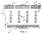
Another screen 70 is illustrated. In this screen a schematic layout of the data acquisition system is illustrated. The data acquisition system has a right chassis portion 72, a center chassis portion 74, and a left chassis portion 76. These portions correspond to specific circuits. The schematic representation also has an application-specific integrated circuit (ASIC) layout 78.
A converter board to connect indicia 80 is also illustrated. Each of the portions 72 through 80 have various boxes therein corresponding on a one-to-one basis with the circuit board in the data acquisition system. Box 82A, 82B, 82C, and 82D correspond to errors found in the critical to quality characteristics. Thus, these components can easily be replaced by merely looking at the schematic representation thereof.
As can be seen, the present invention allows a technician or an assembly person to easily locate and identify the problem in a data acquisition circuit or other complicated circuit without the need to interpret a vast amount of data.
It is inherent in any system that various security procedures and the like may be provided by the systems described herein such as password and user identification.
While the invention has been described in connection with one or more embodiments, it should be understood that the invention is not limited to those embodiments. On the contrary, the invention is intended to cover all alternatives, modifications, and equivalents, as may be included within the spirit and scope of the appended claims.
Claims (23)
1. A system comprising:
a diagnostic system;
a data acquisition system coupled to the diagnostic system;
a computer controller coupled to the data acquisition system;
a display device coupled to the computer controller;
said controller receiving data from said data acquisition system, diagnosing a problem in response to said data, said controller generating a first screen display corresponding to a schematic representation of the data acquisition system, said controller generating a screen indicia on said display device corresponding to a location of a problem on the schematic representation to the data acquisition system, said controller generating a second screen display comprising a boxplot illustrating normalized raw data corresponding to the schematic representation.
2. A system as recited in claim 1 further comprising a computed tomography system, the data acquisition system is disposed with the computed tomography system.
3. A system as recited in claim 2 wherein the computed tomography system comprises a detector assembly, said data acquisition system disposed within said detector assembly.
4. A computed tomography system comprising a system as recited in claim 1 .
5. A system as recited in claim 1 wherein said data is stored in a memory.
6. A system as recited in claim 1 wherein said data is communicated from said data acquisition system.
7. A system as recited in claim 1 wherein said data acquisition system is located remotely from said diagnostic system.
8. A system as recited in claim 1 further comprising a network coupling said computer controller and said data acquisition system.
9. A system as recited in claim 1 wherein said controller has a web browser, said controller generating the screen indicia through said web browser.
10. A system as recited in claim 1 wherein the boxplot is colored to indicate passed or failed data.
11. A diagnostic system for a data acquisition system comprising:
a computer controller coupled to the data acquisition system; and
a display device coupled to the computer controller;
said controller receiving data from said data acquisition system, diagnosing a problem in response to said data, said controller generating a first screen display corresponding to a schematic representation of the date acquisition system, said controller generating a screen indicia on said display device corresponding to a location of a problem on the schematic representation of the data acquisition system, said controller generating a second screen display comprising a boxplot illustrating normalized raw data corresponding to the schematic representation.
12. A diagnostic system as recited in claim 11 further comprising a network coupling said computer controller and said data acquisition system.
13. A diagnostic system as recited in claim 12 wherein said network comprises a public service telephone network.
14. A diagnostic system as recited in claim 12 wherein said network comprises the Internet.
15. A diagnostic system as recited in claim 11 wherein said data is stored in a memory.
16. A diagnostic system as recited in claim 11 wherein said controller has a web browser, said controller generating the screen indicia through said web browser.
17. A diagnostic system as recited in claim 11 wherein said data is communicated from said data acquisition system.
18. A diagnostic system as recited in claim 11 wherein the boxplot is colored to indicate passed or failed data.
19. A method for operating a diagnostic system comprising:
receiving data from a data acquisition system;
diagnosing a problem in response to said data;
generating a first screen display corresponding to a schematic representation of the data acquisition system;
generating a screen indicator on said display device corresponding to a location of a problem on the schematic representation of the data acquisition system; and
generating a second screen display comprising a boxplot illustrating normalized raw data corresponding to the schematic representation.
20. A method as recited in claim 19 wherein receiving data comprises receiving data through an interface.
21. A method as recited in claim 19 wherein receiving data comprises remotely receiving data.
22. A method as recited in claim 19 wherein said data acquisition system is disposed within a CT system.
23. A method as recited in claim 19 further comprising coloring the boxplot is colored to indicate passed or failed data.
Priority Applications (1)
| Application Number | Priority Date | Filing Date | Title |
|---|---|---|---|
| US10/064,128 US7149656B2 (en) | 2002-06-13 | 2002-06-13 | Diagnostic system for a data acquisition system |
Applications Claiming Priority (1)
| Application Number | Priority Date | Filing Date | Title |
|---|---|---|---|
| US10/064,128 US7149656B2 (en) | 2002-06-13 | 2002-06-13 | Diagnostic system for a data acquisition system |
Publications (2)
| Publication Number | Publication Date |
|---|---|
| US20030233215A1 US20030233215A1 (en) | 2003-12-18 |
| US7149656B2 true US7149656B2 (en) | 2006-12-12 |
Family
ID=29731569
Family Applications (1)
| Application Number | Title | Priority Date | Filing Date |
|---|---|---|---|
| US10/064,128 Expired - Lifetime US7149656B2 (en) | 2002-06-13 | 2002-06-13 | Diagnostic system for a data acquisition system |
Country Status (1)
| Country | Link |
|---|---|
| US (1) | US7149656B2 (en) |
Cited By (1)
| Publication number | Priority date | Publication date | Assignee | Title |
|---|---|---|---|---|
| US20080034257A1 (en) * | 2006-08-07 | 2008-02-07 | Siemens Aktiengesellschaft | Remote diagnosis system for medical appliances of modular design |
Families Citing this family (2)
| Publication number | Priority date | Publication date | Assignee | Title |
|---|---|---|---|---|
| US20070030287A1 (en) * | 2005-08-04 | 2007-02-08 | Honeywell International Inc. | Visual comparison of data set with data subset |
| US20080126868A1 (en) * | 2006-09-01 | 2008-05-29 | Murray David W | System and method for storing embedded diagnostic test failure reports on a faulty component |
Citations (11)
| Publication number | Priority date | Publication date | Assignee | Title |
|---|---|---|---|---|
| US5754451A (en) * | 1996-02-29 | 1998-05-19 | Raytheon Company | Preventative maintenance and diagonstic system |
| US5807256A (en) * | 1993-03-01 | 1998-09-15 | Kabushiki Kaisha Toshiba | Medical information processing system for supporting diagnosis |
| US6239438B1 (en) * | 1998-11-19 | 2001-05-29 | General Electric Company | Dual acquisition imaging method and apparatus |
| US6298454B1 (en) * | 1999-02-22 | 2001-10-02 | Fisher-Rosemount Systems, Inc. | Diagnostics in a process control system |
| US6345113B1 (en) * | 1999-01-12 | 2002-02-05 | Analogic Corporation | Apparatus and method for processing object data in computed tomography data using object projections |
| US20020082862A1 (en) * | 2000-12-22 | 2002-06-27 | Kelley Raymond J. | Web-based medical diagnostic system financial operation planning system and method |
| US20020085674A1 (en) * | 2000-12-29 | 2002-07-04 | Price John Scott | Radiography device with flat panel X-ray source |
| US20020123864A1 (en) * | 2001-03-01 | 2002-09-05 | Evren Eryurek | Remote analysis of process control plant data |
| US6598011B1 (en) * | 1998-11-25 | 2003-07-22 | Ianne Mae Howards Koritzinsky | Medical diagnostic system services interface |
| US6656683B1 (en) * | 2000-07-05 | 2003-12-02 | Board Of Regents, The University Of Texas System | Laser scanning cytology with digital image capture |
| US6678703B2 (en) * | 2000-06-22 | 2004-01-13 | Radvault, Inc. | Medical image management system and method |
-
2002
- 2002-06-13 US US10/064,128 patent/US7149656B2/en not_active Expired - Lifetime
Patent Citations (11)
| Publication number | Priority date | Publication date | Assignee | Title |
|---|---|---|---|---|
| US5807256A (en) * | 1993-03-01 | 1998-09-15 | Kabushiki Kaisha Toshiba | Medical information processing system for supporting diagnosis |
| US5754451A (en) * | 1996-02-29 | 1998-05-19 | Raytheon Company | Preventative maintenance and diagonstic system |
| US6239438B1 (en) * | 1998-11-19 | 2001-05-29 | General Electric Company | Dual acquisition imaging method and apparatus |
| US6598011B1 (en) * | 1998-11-25 | 2003-07-22 | Ianne Mae Howards Koritzinsky | Medical diagnostic system services interface |
| US6345113B1 (en) * | 1999-01-12 | 2002-02-05 | Analogic Corporation | Apparatus and method for processing object data in computed tomography data using object projections |
| US6298454B1 (en) * | 1999-02-22 | 2001-10-02 | Fisher-Rosemount Systems, Inc. | Diagnostics in a process control system |
| US6678703B2 (en) * | 2000-06-22 | 2004-01-13 | Radvault, Inc. | Medical image management system and method |
| US6656683B1 (en) * | 2000-07-05 | 2003-12-02 | Board Of Regents, The University Of Texas System | Laser scanning cytology with digital image capture |
| US20020082862A1 (en) * | 2000-12-22 | 2002-06-27 | Kelley Raymond J. | Web-based medical diagnostic system financial operation planning system and method |
| US20020085674A1 (en) * | 2000-12-29 | 2002-07-04 | Price John Scott | Radiography device with flat panel X-ray source |
| US20020123864A1 (en) * | 2001-03-01 | 2002-09-05 | Evren Eryurek | Remote analysis of process control plant data |
Non-Patent Citations (1)
| Title |
|---|
| Gerald E. Dallal, "look at the data", 1999, pp. 1-4. * |
Cited By (2)
| Publication number | Priority date | Publication date | Assignee | Title |
|---|---|---|---|---|
| US20080034257A1 (en) * | 2006-08-07 | 2008-02-07 | Siemens Aktiengesellschaft | Remote diagnosis system for medical appliances of modular design |
| US8024612B2 (en) * | 2006-08-07 | 2011-09-20 | Siemens Aktiengesellschaft | Remote diagnosis system for medical appliances of modular design |
Also Published As
| Publication number | Publication date |
|---|---|
| US20030233215A1 (en) | 2003-12-18 |
Similar Documents
| Publication | Publication Date | Title |
|---|---|---|
| US6192302B1 (en) | Motor vehicle diagnostic system and apparatus | |
| US6275559B1 (en) | Method and system for diagnosing faults in imaging scanners | |
| US20030200483A1 (en) | Electronic test program that can distinguish results | |
| EP0050014A1 (en) | Automatic test system | |
| US7729524B2 (en) | Assessment of radiographic systems and operators using task-based phantom | |
| US6882961B2 (en) | Method and system for providing diagnostics for a work machines | |
| US5712972A (en) | Identification of faults in data paths and functional units of a central processing unit by a systematic execution of test instructions | |
| JP2007102388A (en) | Maintenance support device, maintenance support method, maintenance support system, controller, and control method | |
| US7350106B2 (en) | Device for aiding the locating of failure of a complex system | |
| CN111954890A (en) | Terminal device, work machine system, information processing method, and server device | |
| US6850868B2 (en) | Maintenance system for analyzing instrument | |
| US20020170000A1 (en) | Test and on-board programming station | |
| US7461296B2 (en) | Method to test a software system for technical systems | |
| US7149656B2 (en) | Diagnostic system for a data acquisition system | |
| KR102082575B1 (en) | System for supporting operator in nuclear plant and method for supporting operator using the same | |
| US20040061722A1 (en) | Passdown database and flow chart | |
| KR100293559B1 (en) | Method for automatically searching error of component in automatic test apparatus | |
| WO2020204140A1 (en) | Medial information processing device and medical information processing method | |
| CN210862747U (en) | Detection device for medical equipment fault detection | |
| JP3084013B2 (en) | Gas appliance failure diagnosis method and repair method using the same | |
| JP2925286B2 (en) | Fault diagnosis system | |
| TW202217486A (en) | Mobile equipment diagnostic device and method for displaying equipment diagnostic information | |
| JP3197524B2 (en) | Diagnosis device for hot water supply equipment | |
| JPH08178278A (en) | Repairing method and repair supporting apparatus for gas apparatus or the like | |
| KR20010076717A (en) | Advanced Alarm System of Main Control Room in Nuclear Power Plant |
Legal Events
| Date | Code | Title | Description |
|---|---|---|---|
| STCF | Information on status: patent grant |
Free format text: PATENTED CASE |
|
| FPAY | Fee payment |
Year of fee payment: 4 |
|
| FPAY | Fee payment |
Year of fee payment: 8 |
|
| MAFP | Maintenance fee payment |
Free format text: PAYMENT OF MAINTENANCE FEE, 12TH YEAR, LARGE ENTITY (ORIGINAL EVENT CODE: M1553) Year of fee payment: 12 |