US7124660B2 - Hex-axis horizontal movement dynamic simulator - Google Patents
Hex-axis horizontal movement dynamic simulator Download PDFInfo
- Publication number
- US7124660B2 US7124660B2 US10/622,506 US62250603A US7124660B2 US 7124660 B2 US7124660 B2 US 7124660B2 US 62250603 A US62250603 A US 62250603A US 7124660 B2 US7124660 B2 US 7124660B2
- Authority
- US
- United States
- Prior art keywords
- yoke
- sliding
- plate
- guide
- fastened
- Prior art date
- Legal status (The legal status is an assumption and is not a legal conclusion. Google has not performed a legal analysis and makes no representation as to the accuracy of the status listed.)
- Expired - Fee Related, expires
Links
Images


Classifications
-
- B—PERFORMING OPERATIONS; TRANSPORTING
- B25—HAND TOOLS; PORTABLE POWER-DRIVEN TOOLS; MANIPULATORS
- B25J—MANIPULATORS; CHAMBERS PROVIDED WITH MANIPULATION DEVICES
- B25J17/00—Joints
- B25J17/02—Wrist joints
- B25J17/0258—Two-dimensional joints
- B25J17/0266—Two-dimensional joints comprising more than two actuating or connecting rods
-
- A—HUMAN NECESSITIES
- A47—FURNITURE; DOMESTIC ARTICLES OR APPLIANCES; COFFEE MILLS; SPICE MILLS; SUCTION CLEANERS IN GENERAL
- A47B—TABLES; DESKS; OFFICE FURNITURE; CABINETS; DRAWERS; GENERAL DETAILS OF FURNITURE
- A47B91/00—Feet for furniture in general
- A47B91/16—Self-levelling legs
-
- B—PERFORMING OPERATIONS; TRANSPORTING
- B25—HAND TOOLS; PORTABLE POWER-DRIVEN TOOLS; MANIPULATORS
- B25J—MANIPULATORS; CHAMBERS PROVIDED WITH MANIPULATION DEVICES
- B25J9/00—Programme-controlled manipulators
- B25J9/003—Programme-controlled manipulators having parallel kinematics
- B25J9/0033—Programme-controlled manipulators having parallel kinematics with kinematics chains having a prismatic joint at the base
- B25J9/0042—Programme-controlled manipulators having parallel kinematics with kinematics chains having a prismatic joint at the base with kinematics chains of the type prismatic-universal-universal
-
- G—PHYSICS
- G09—EDUCATION; CRYPTOGRAPHY; DISPLAY; ADVERTISING; SEALS
- G09B—EDUCATIONAL OR DEMONSTRATION APPLIANCES; APPLIANCES FOR TEACHING, OR COMMUNICATING WITH, THE BLIND, DEAF OR MUTE; MODELS; PLANETARIA; GLOBES; MAPS; DIAGRAMS
- G09B9/00—Simulators for teaching or training purposes
- G09B9/02—Simulators for teaching or training purposes for teaching control of vehicles or other craft
-
- Y—GENERAL TAGGING OF NEW TECHNOLOGICAL DEVELOPMENTS; GENERAL TAGGING OF CROSS-SECTIONAL TECHNOLOGIES SPANNING OVER SEVERAL SECTIONS OF THE IPC; TECHNICAL SUBJECTS COVERED BY FORMER USPC CROSS-REFERENCE ART COLLECTIONS [XRACs] AND DIGESTS
- Y10—TECHNICAL SUBJECTS COVERED BY FORMER USPC
- Y10T—TECHNICAL SUBJECTS COVERED BY FORMER US CLASSIFICATION
- Y10T74/00—Machine element or mechanism
- Y10T74/20—Control lever and linkage systems
- Y10T74/20207—Multiple controlling elements for single controlled element
- Y10T74/20305—Robotic arm
- Y10T74/20329—Joint between elements
Definitions
- the invention relates to a hex-axis horizontal movement dynamic simulator and more particularly to 6-degrees-of-freedom motion simulating equipment used in modular design.
- a goal of the present invention is to provide a solution to the above-described problems of the conventional Stewart Platform by employing a modular design instead of the hydraulic or pneumatic system used by the conventional Stewart Platform.
- Another goal of the present invention is to provide a hex-axis horizontal movement dynamic simulator that can simulate the motion of 6 degrees of freedom without employing a hydraulic or pneumatic system.
- a further goal of the invention is to provide a hex-axis horizontal movement dynamic simulator having a modular structure that comprises three modular movement control units of the same structure.
- the modular movement control units are located at positions relative to each other forming three sides of an equilateral triangle and are pivoted to a load-carrying platform by a universal-joint yoke mechanism corresponding to each of the three movement control units.
- a further goal of the invention is to provide a specific structure of a modular movement control unit that can precisely control the movement of the load-carrying platform and provide a motion simulation platform having 6 degrees of freedom.
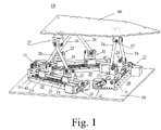
- FIG. 1 illustrates a first embodiment of the hex-axis horizontal movement dynamic simulator of the invention that has three sets of movement control units of the same structure located separately at the positions forming three sides of an equilateral triangle.
- FIG. 2 illustrates the hex-axis horizontal movement dynamic simulator of FIG. 1 showing the variation of translation and angular motion of the load-carrying platform.
- FIG. 3 is a schematic drawing of the invention shown in FIG. 2 as viewed from another direction.
- FIG. 4 is a disassembly drawing showing the parts of the movement control unit illustrated in FIG. 1 .
- FIG. 5 illustrates a second embodiment of the hex-axis horizontal movement dynamic simulator having three sets of movement control units of the same structure located separately at the positions forming three sides of an equilateral triangle.
- FIG. 6 is a disassembly drawing showing parts of the movement control unit illustrated in FIG. 5 .
- FIG. 7 illustrates a third type of embodiment of the hex-axis horizontal movement dynamic simulator having three sets of movement control units of the same structure located separately at the positions forming three sides of an equilateral triangle.
- FIG. 8 is a disassembly drawing showing the parts of the movement control unit illustrated in FIG. 7 .
- a key point of the invention is that no hydraulic or pneumatic system is used in a hex-axis motion simulator 10 .
- For each universal-joint yoke mechanism 27 one end of each of two fixed-length connecting rods 26 are pivoted to the universal-joint yoke mechanism 27 and the other ends of the connecting rods 26 are separately connected to a transmission-joint yoke mechanism 25 .
- each transmission-joint yoke mechanism 25 is pivoted to a sliding seat 24 and the rectilinear translation motion and position of each transmission-joint yoke mechanism 25 is controlled by controlling the rectilinear translation and position of the corresponding sliding seat 24 so as to generate a motion of 6 degrees of freedom that controls the spatial motion and position of the load-carrying platform.
- Hex-axis horizontal movement dynamic simulator 10 comprises three movement control units 20 , of the same structure, that are fixed on a foundation 50 at the locations relative to each other forming three sides of an equilateral triangle.
- Each of the three movement control units 20 is pivoted to the load carrying platform 60 by a universal-joint yoke mechanism 27 .
- the locations at which the three universal-joint yoke mechanisms 27 are pivoted to the load-carrying platform 60 form an equilateral triangle.
- Each movement control unit 20 is symmetrically structured to comprise a universal-joint yoke mechanism 27 , two connecting rods of fixed length 26 , two transmission-joint yoke mechanisms 25 , two sliding seats 24 , two lead screws 23 , two servo-driving mechanisms 22 , and a rectilinear translation guide 21 . Since universal-joint yoke mechanism 27 is pivotally connected to load-carrying platform 60 , it can generate a motion of 1 degree of freedom relative to load-carrying platform 60 . Since one end of each of the two connecting rods 26 is pivotally connected to the same universal-joint yoke mechanism 27 , the connecting rod can generate a motion of 2 degrees of freedom.
- the end of the connecting rod pivoted to the universal-joint yoke mechanism 27 has 3 degrees of freedom for generating a spatial motion relative to the load-carrying platform.
- the other ends of the two connecting rods are symmetrically pivoted to separate driving joint yoke mechanisms 25 that can generate a spatial motion of 2 degrees of freedom. Since the transmission-joint yoke mechanism 25 of each connecting rod 26 is pivoted to a sliding seat 24 , the transmission-joint yoke mechanism 25 has 1 degree of freedom for generating a spatial motion relative to the sliding seat 24 . Therefore, the end of the connecting rod 26 pivoted to the transmission-joint yoke mechanism 25 has 3 degrees of freedom relative to the sliding seat 24 for spatial motion.
- both ends of each connecting rod 26 of each movement control unit 20 have 3 degrees of freedom for generating a spatial motion. Since all connecting rods are fixed-length rigid bodies, when the sliding seat 24 is displaced rectilinearly, the transmission-joint yoke mechanism 25 on one end of the connecting rod 26 is restricted to rectilinear translation together with the sliding seat 24 , which enables the connecting rod 26 to generate a spatial displacement of 6 degrees of freedom. Through the variation of spatial position of every connecting rod 26 , the universal-joint yoke mechanism 27 on the other end of the connecting rod 26 will generate a relative spatial-displacement following the rectilinear displacement of the transmission-joint yoke mechanism 25 .
- the spatial position of the connecting rod 26 on the transmission-joint yoke mechanism 25 associated with 6 degrees of freedom will vary. That is, the universal-joint yoke mechanism 27 on one end of each connecting rod 26 will change its spatial position relative to the transmission-joint yoke mechanism 25 and actuate the load-carrying platform 60 to vary its spatial position.
- FIGS. 1–3 corresponds to the rectilinear displacement of different sliding seats 24 , which slide on different movement control units 20 that are respectively located at the positions forming three sides of an equilateral triangle.
- the sliding seats 24 may have relative displacements for the load-carrying platform 60 . Therefore, through the synchronous and precise control of the rectilinear movement of each sliding seat 24 of each movement control unit 20 , such as may be provided by a computer system, the spatial movement of each universal-joint yoke mechanism 27 relative to the others can be precisely controlled to achieve a precise control of the motion of load-carrying platform 60 and to generate linear and angular displacement spatially.
- the mechanism that enables each sliding seat 24 of each movement control unit 20 to generate a rectilinear motion comprises two lead screws 23 , two servo-driving mechanisms 22 having servo-motors 221 , a rectilinear translation guide 21 having two guide seats 212 and two straight sliding rails 211 .
- Each sliding seat 24 has a female screw thread that engages with the lead screw 23 .
- the servo-motor 221 of the servo-driving mechanism 22 is employed to drive the lead screw 23 to rotate, which enables the sliding seat 24 on one of the guide seats 212 of the rectilinear translation guide 21 to be guided by the straight sliding rail 211 and to generate rectilinear displacement.
- each sliding seat 24 can be precisely controlled by the precise control of the rotating speed and angular displacement of the servo-motor 221 of each servo-driving mechanism 22 , through which a precise control of the variation of linear and angular displacement of the load-carrying platform 60 can be achieved.
- the first embodiment of the movement control unit is shown in FIGS. 1–4 and comprises a base seat 40 , a universal joint yoke mechanism 27 , two connecting rods of fixed length 26 , two transmission-joint yoke mechanisms 25 , two sliding seats 24 , two lead screws 23 , two servo-driving mechanisms 22 , and a rectilinear translation guide 21 .
- the base seat 40 is a longitudinal plate fastened to the foundation 50 by bolt.
- the rectilinear translation guide 21 has two linear sliding rails 211 parallel to each other and two identical guide seats 212 .
- each guide seat 212 can be installed on and match the two straight sliding rails 211 and slide on the two straight sliding rails along the guiding direction.
- Each servo-driving mechanism 22 comprises a servo-motor 221 assembled with a driving pulley 222 , a driving belt 223 , a driven pulley 224 and a bearing plate 225 that drives a lead screw 23 .
- the bearing plate 225 of each servo-driving mechanism 22 is installed at a position near a different end of the base seat 40 so as to form a bracket for mounting the two lead screws 23 with bearings and to have the two lead screws 23 parallel to the two straight sliding rails 211 .
- the driving pulley 222 is mounted on the driving shaft of the servo-motor 221
- the driven pulley 224 is mounted on the lead screw 23 .
- the driving pulley 222 and the driven pulley 224 are connected by the driving belt 223 .
- the sliding seat 24 is rectangular shaped and fastened to the guide seat 212 of the rectilinear translation guide 21 .
- two penetrating holes 241 , 242 are prepared.
- Hole 241 has a female screw thread and engages with the lead screw 23 .
- the other hole 242 is a passage for another lead screw 23 to pass through.
- a mounting recess 243 for pivotally mounting the transmission joint yoke mechanism 25 .
- the transmission-joint yoke mechanism 25 comprises a U-shaped yoke 251 and a T-shaped pivot axis.
- the horizontal stub shaft formed on both sides of the T-shaped pivot axis is pivoted to the two vertical portions of the U-shaped yoke 251 by a bearing and nut that enable the perpendicular stub shaft of the T-shaped pivot axis to have 1 degree of freedom of rotational motion relative to the U-shaped yoke 251 .
- a mounting shaft 253 that is pivotally mounted to the mounting recess 243 by a bearing and nut that provide the transmission joint yoke mechanism 25 with 1 degree of freedom of rotational motion relative to the sliding seat 24 .
- the perpendicular stub shaft of the T-shaped pivot axis 252 of each transmission-joint yoke mechanism 25 has 2 degrees of freedom of rotational motion relative to the sliding seat 24 to which it is mounted.
- the universal-joint yoke mechanism 27 comprises an inverse U-shaped yoke 271 , a cardan shaft 272 , a neck-ring seat 274 , and a cover plate 275 .
- the left and right horizontal stub shafts formed on both sides of the cardan shaft 272 are pivoted to the two vertical portions of the inverse U-shaped yoke 271 by a bearing and nut that enable the perpendicular stub shaft formed on the front and rear side of the cardan shaft ( 272 ) to have 1 degree of freedom of rotational motion relative to the inverse U-shaped yoke 271 .
- the inverse U-shaped yoke 271 On the top side of the inverse U-shaped yoke 271 , is a mounting shaft 273 that is pivoted to the neck-ring seat 274 by a bearing. A cover plate 275 is mounted on the upper side of the neck-ring seat 274 , through which the whole assembly of the universal-joint yoke mechanism 27 is mounted on the load-carrying platform 60 .
- the inverse U-shaped yoke 271 has 1 degree of freedom of rotational motion relative to the neck-ring seat 274 or the cover plate 275 .
- the perpendicular stub shaft on the front and rear side of the cardan shaft 272 of the inverse U-shaped yoke 271 has 2 degrees of freedom of rotational motion relative to the neck-ring seat 274 or cover-plate 275 .
- Every connecting rod 26 has a fixed length.
- On both ends of the connecting rod 26 are pivoting holes through which the front end of the connecting rod is pivotally connected to the front perpendicular stub shaft or rear perpendicular stub shaft of the cardan shaft 272 of the universal-joint 27 .
- the pivoting hole on the front end of the connecting rod 26 has 1 degree of freedom of rotational motion relative to the perpendicular stub shaft of the cardan shaft 272 .
- the pivoting hole on the front end of every connecting rod 26 has 3 degrees of freedom of rotational motion relative to the neck-ring seat 274 or cover plate 275 .
- the pivoting hole on the rear end of every connecting rod 26 is pivotally connected to the perpendicular stub shaft of the T-shaped pivot axis 252 by a bearing and nut that provide the pivoting hole on the rear end of every connecting rod 26 with 1 degree of freedom of rotational motion relative to the perpendicular stub shaft of the T-shaped pivot axis 252 .
- the pivoting hole on the rear end of every connecting rod 26 has 3 degrees of freedom of rotational motion relative to the sliding seat 24 .
- each end of the connecting rod 26 has 3 degrees of freedom of rotational motion, the whole connecting rod 26 has 6 degrees of freedom for generating a spatial motion.
- the above-mentioned mechanism as verified by the equation of mobility in Spatial Mechanism, generates a spatial motion of 6 degrees of freedom, according to Gruebler's formula for a spatial mechanism:
- the relative rotating angle and rotating speed of the servo-motor 221 of the servo-driving mechanism 22 of each movement control unit 20 can be synchronously controlled.
- the sliding seat 24 and transmission-joint yoke mechanism 25 on each of the three movement control units can synchronously generate different rectilinear movements to drive the connecting rods 26 to generate relative spatial-displacements and control the relative spatial-movement of each universal-joint yoke mechanism 27 , thus enabling the load-carrying platform 60 to vary its posture and angular position so as to simulate the state of a carrier (such as vehicle, ship, airplane and roller coaster etc.) making a spatial motion of 6 degrees of freedom.
- a carrier such as vehicle, ship, airplane and roller coaster etc.
- the second embodiment of the movement control unit 20 is shown in FIGS. 5 and 6 and comprises a machine bed 41 , one universal-joint yoke mechanism 27 , two fixed-length connecting rods, two transmission-joint yoke mechanisms 25 , two sliding seats 24 , two lead screws 23 , two servo-driving mechanisms 22 , and a rectilinear translation guide 21 .
- the components of the universal-joint yoke mechanism 27 , the connecting rod 26 , the transmission-joint yoke mechanism 25 , the lead screw 23 , the servo-driving mechanism 22 , and the rectilinear translation guide 21 are the same as those in the first embodiment of the invention.
- the machine bed 41 of the second embodiment of the invention is a rectangular stand made of a metal plate having an inverse U-shaped cross-section that is fastened on the foundation 50 .
- a cover plate 411 is mounted on both the left and right ends of the machine bed 41 with holes and an opening prepared at appropriate positions.
- the servo-motor 221 of the servo-driving mechanism 22 is installed inside the machine bed 41 .
- the driving shaft of the servo-motor 221 extends outside the machine bed 41 .
- a driving pulley 222 is mounted and fastened on the driving shaft of the driving-servo motor 221 .
- Two support plates 227 of the servo-driving mechanism 22 are installed at places closed to both ends of the machine bed 41 to form the support for pivotally mounting the two lead screws 23 by bearings in a position parallel to the two straight sliding rails 211 of the rectilinear translation guide 21 .
- the driven pulley 224 is mounted and fastened on the lead screw 23 with a transmission belt installed on and passing through the driving pulley 222 and driven pulley 224 . Therefore, the driving power of the servo-motor 221 is transmitted to the lead screw 23 through the driving pulley 222 , the transmission belt 223 , and the driven pulley 224 .
- the sliding seat 24 employed in the second embodiment of the invention comprises a sliding block 244 and a neck ring seat 246 .
- the sliding block 244 is fastened on the guide seat 212 of the rectilinear translation guide mechanism 21 .
- two holes are provided, one of which has a female screw thread and engages with a lead screw 23 .
- the other hole serves as the passage for another lead screw to pass through.
- the neck-ring seat 246 is fastened on the top side of the sliding block 244 or a fastening plate 245 is installed on the top side of the sliding block 244 , first, and then the neck-ring 246 is fastened on the fastening plate 245 .
- the mounting shaft 253 of the U-shaped yoke 251 of the transmission-joint yoke mechanism 25 is pivoted to the circular access on the tope side of the neck-ring seat 246 by a bearing and related parts.
- the sliding seat 24 employed in the second embodiment and the first embodiment can be exchanged and used in either of the two embodiments or in other embodiments of the invention.
- the third embodiment of the movement control unit 20 is shown in FIGS. 7 and 8 and comprises a base seat 40 , a universal-joint yoke mechanism 29 , two fixed-length connecting rods 26 , two sliding yoke mechanisms 28 , two leading screws 23 , two servo-driving mechanisms 22 , and a rectilinear translation guide 21 .
- the connecting rod 26 , lead screw 23 , servo-driving mechanism 22 , and rectilinear translation guide 21 are the same as those employed in the first embodiment.
- the structure of the universal-joint yoke mechanism 29 is similar to the sliding yoke mechanism 28 .
- the universal-joint yoke mechanism 29 of the third embodiment comprises an inverse U-shaped yoke assembly 291 , a pivoting plate 293 , a pivoting shaft 295 , two fixing blocks 296 , an L-shaped yoke plate 297 , a fastening yoke plate 298 , and two cover plates 299 .
- the L-shaped yoke plate is formed by a horizontal portion and a vertical portion. The horizontal portion is fastened on the load-carrying platform 60 . A vertical portion hole is provided for mounting a shaft.
- the fastening yoke plate 298 is a plate-shaped member with appropriate thickness having an appearance symmetric to that of the vertical portion of the L-shaped yoke plate 297 .
- a shaft mounting hole is also provided on the fastening yoke plate 298 , which is to be assembled with the L-shaped yoke plate 297 to form a yoke assembly.
- the pivoting plate 293 is rectangular shape with a pivoting access in its center position and horizontal stub shafts 294 extended symmetrically from both sides opposite to each other that pivotally mount in the hole on the L-shaped yoke plate 297 and the fastening yoke plate 298 by bearings and related parts.
- the two cover plates are fastened on one side of the vertical portion of the L-shaped yoke plate 297 and the fastening yoke plate 298 to fix the whole assembly and provide the pivoting plate 293 with 1 degree of freedom of rotational motion relative to the L-shaped yoke plate 297 and the fastening yoke plate 298 .
- the yoke assembly 291 has a mounting shaft 292 extended upwardly from its top side and is mounted in the pivoting access in the center position of the pivoting plate 293 by a bearing, and a cover is fastened on the mounting surface of the pivoting plate to fix the assembly.
- the yoke assembly has 1 degree of freedom of rotational motion relative to the pivoting plate 293 and has 2 degrees of freedom of motion relative to the L-shaped yoke plate 297 and the fastening yoke plate 298 .
- the bottom side of the two flanks of the yoke assembly 291 has a semicircular recess, and the fixing block 296 also has a corresponding semicircular recess on the top side.
- a shaft 295 is pivotally installed by fixing the two fixing blocks on the bottom side of the two flanks of the yoke assembly 291 , and both ends of the pivoting shaft 295 can be pivotally connected to the connecting rod 26 so as to provide the pivot hole on the front end of each connecting rod with 1 degree of freedom of rotational motion relative to the yoke assembly 291 and 3 degrees of freedom of rotational motion relative to the L-shaped yoke plate 297 and the fastening yoke plate 298 .
- the sliding yoke mechanism 28 employed in the third embodiment comprises a U-shaped yoke assembly 281 , a pivoting plate 283 , a shaft 285 , two fixing blocks 286 , an L-shaped sliding yoke plate 287 , a sliding fastening plate 288 , and two cover plates 289 .
- the L-shaped sliding yoke plate 287 has a horizontal portion and a vertical portion and is fastened on the guide seat 212 of the rectilinear translation guide 21 through its horizontal portion.
- the L-shaped sliding yoke plate 287 has two penetrating holes, one of which has a female screw thread and engages with the lead screw 23 . The other hole serves as a passage for another lead screw 23 to pass through.
- the vertical portion of the L-shaped sliding yoke plate 287 has a pivoting hole.
- the sliding fastening plate 288 is a plate-shaped member of appropriate thickness and has an appearance symmetric to that of the vertical portion of the L-shaped sliding yoke plate.
- Two penetrating holes and a pivoting hole are provided on the sliding fastening plate 288 .
- the two penetrating holes are for the two lead screws 23 to pass through.
- a yoke assembly is formed by assembling the sliding fastening plate 288 and the L-shaped sliding yoke plate 287 .
- the pivoting plate 283 is rectangular shaped with a pivoting access in a center position and horizontal stub shafts 284 extended symmetrically from both sides opposite to each other that pivotally mount in the hole on the L-shaped sliding yoke plate 287 and the sliding fastening yoke plate 288 by a bearing and related parts.
- Two cover plates are fastened on one side of the vertical portion of the L-shaped sliding yoke plate 287 and the sliding fastening plate 288 to fix the whole assembly so that the pivoting plate 283 has 1 degree of freedom of rotational motion relative to the L-shaped sliding yoke plate 287 and the sliding fastening plate 288 .
- the yoke assembly 281 has a mounting shaft 282 extended downwardly from its bottom side that is pivotally mounted in the pivoting access in the center position of the pivoting plate 283 by a bearing and related parts. A cover is fastened on the pivoting plate 283 to fix the assembly.
- the U-shaped yoke assembly 281 has 1 degree of freedom of rotational motion relative to the pivoting plate 283 and has 2 degrees of freedom of rotational motion relative to the L-shaped sliding yoke plate 287 and the sliding fastening plate 288 .
- the top side of the two vertical portions of the U-shaped yoke assembly has a semicircular recess, and a corresponding semicircular recess is provided on the fixing block 286 on the bottom side.
- a shaft 285 is pivotally installed by fixing the two fixing blocks 286 on the top side of the U-shaped yoke assembly, and both ends of the pivoting shaft 285 can be pivotally connected to the connecting rod 26 so as to provide the pivot hole on the rear end of the connecting rod 26 with 1 degree of freedom of rotational motion relative to the U-shaped yoke assembly 281 and 3 degrees of freedom of rotational motion relative to the L-shaped sliding yoke plate 287 and the sliding fastening plate 288 . Since both ends of the connecting rod 26 have 3 degrees of freedom of rotational motion, each connecting rod 26 has 6 degrees of freedom of rotational motion in space.
Abstract
Description
Where
Claims (7)
Applications Claiming Priority (2)
| Application Number | Priority Date | Filing Date | Title |
|---|---|---|---|
| TW091116413 | 2002-07-23 | ||
| TW091116413A TW546595B (en) | 2002-07-23 | 2002-07-23 | Six-axis translation-type dynamic simulation device |
Publications (2)
| Publication Number | Publication Date |
|---|---|
| US20040144288A1 US20040144288A1 (en) | 2004-07-29 |
| US7124660B2 true US7124660B2 (en) | 2006-10-24 |
Family
ID=29730036
Family Applications (1)
| Application Number | Title | Priority Date | Filing Date |
|---|---|---|---|
| US10/622,506 Expired - Fee Related US7124660B2 (en) | 2002-07-23 | 2003-07-21 | Hex-axis horizontal movement dynamic simulator |
Country Status (3)
| Country | Link |
|---|---|
| US (1) | US7124660B2 (en) |
| JP (1) | JP3919712B2 (en) |
| TW (1) | TW546595B (en) |
Cited By (48)
| Publication number | Priority date | Publication date | Assignee | Title |
|---|---|---|---|---|
| US20060241810A1 (en) * | 2005-04-20 | 2006-10-26 | Dan Zhang | High stiffness, high accuracy, parallel kinematic, three degree of freedom motion platform |
| US20060254380A1 (en) * | 2004-06-24 | 2006-11-16 | Dlr Deutsches Zentrum Fur Luft-Und Raumfahrt E.V. | Movement device |
| US20080078266A1 (en) * | 2006-09-29 | 2008-04-03 | Abb Patent Gmbh | Jig particularly for the positioning of articles |
| US20090255364A1 (en) * | 2008-04-10 | 2009-10-15 | Murata Machinery, Ltd. | Parallel mechanism |
| US20090321631A1 (en) * | 2008-06-25 | 2009-12-31 | Axcelis Technologies, Inc. | Low-inertia multi-axis multi-directional mechanically scanned ion implantation system |
| US20100032543A1 (en) * | 2006-03-01 | 2010-02-11 | Jan Van Der Tempel | Vessel, motion platform, method for compensating motions of a vessel and use of a stewart platform |
| US20100078866A1 (en) * | 2006-12-21 | 2010-04-01 | Hexagon Metrology Ab | Method and device for the compensation of geometrical errors in machining machinery |
| US20100122602A1 (en) * | 2008-11-17 | 2010-05-20 | Marcroft Sacha L | Parallel kinematic positioning system |
| US20100273132A1 (en) * | 2006-08-18 | 2010-10-28 | Zen Technologies Ltd. | Motion platform system |
| DE102010024504A1 (en) * | 2010-06-21 | 2011-12-22 | Technische Universität Braunschweig | Machine, particularly robot, comprises motor, and drive unit, which is driven by motor, where output part is provided, which is driven by drive unit |
| US20120180593A1 (en) * | 2010-07-13 | 2012-07-19 | Thales | Hexapod actuator device |
| US20130153792A1 (en) * | 2011-12-16 | 2013-06-20 | Cymer, Inc | Droplet generator steering system |
| US20130158565A1 (en) * | 2009-11-27 | 2013-06-20 | Mcmaster University | Automated in-bore mr guided robotic diagnostic and therapeutic system |
| US20140197327A1 (en) * | 2013-01-17 | 2014-07-17 | Ims Nanofabrication Ag | High-voltage insulation device for charged-particle optical apparatus |
| US9099277B2 (en) | 2013-07-17 | 2015-08-04 | Ims Nanofabrication Ag | Pattern definition device having multiple blanking arrays |
| US20150308609A1 (en) * | 2012-12-21 | 2015-10-29 | Materialise N.V. | Apparatus and methods of positioning an object using an adjustment block |
| US9214314B1 (en) * | 2015-03-10 | 2015-12-15 | Varian Semiconductor Equipment Associates, Inc. | Ion beam manipulator |
| US9269543B2 (en) | 2014-02-28 | 2016-02-23 | Ims Nanofabrication Ag | Compensation of defective beamlets in a charged-particle multi-beam exposure tool |
| US20160140862A1 (en) * | 2012-11-14 | 2016-05-19 | E2M Technologies Bv | Six-degree-of-freedom motion simulator assembly |
| US9373482B2 (en) | 2014-07-10 | 2016-06-21 | Ims Nanofabrication Ag | Customizing a particle-beam writer using a convolution kernel |
| US9443699B2 (en) | 2014-04-25 | 2016-09-13 | Ims Nanofabrication Ag | Multi-beam tool for cutting patterns |
| US9495499B2 (en) | 2014-05-30 | 2016-11-15 | Ims Nanofabrication Ag | Compensation of dose inhomogeneity using overlapping exposure spots |
| US9568907B2 (en) | 2014-09-05 | 2017-02-14 | Ims Nanofabrication Ag | Correction of short-range dislocations in a multi-beam writer |
| US9653263B2 (en) | 2015-03-17 | 2017-05-16 | Ims Nanofabrication Ag | Multi-beam writing of pattern areas of relaxed critical dimension |
| US9799487B2 (en) | 2015-03-18 | 2017-10-24 | Ims Nanofabrication Ag | Bi-directional double-pass multi-beam writing |
| US20180096622A1 (en) * | 2015-04-02 | 2018-04-05 | Mclaren Applied Technologies Limited | Motion arrangement |
| US20180222042A1 (en) * | 2015-10-02 | 2018-08-09 | Beckhoff Automation Gmbh | Robot, xy table for a robot and linear transport system |
| US20180297195A1 (en) * | 2015-10-26 | 2018-10-18 | Sony Corporation | Parallel link robot and operation apparatus |
| US20180326587A1 (en) * | 2015-11-25 | 2018-11-15 | Mitsubishi Electric Corporation | Parallel link device |
| US10325757B2 (en) | 2017-01-27 | 2019-06-18 | Ims Nanofabrication Gmbh | Advanced dose-level quantization of multibeam-writers |
| US10325756B2 (en) | 2016-06-13 | 2019-06-18 | Ims Nanofabrication Gmbh | Method for compensating pattern placement errors caused by variation of pattern exposure density in a multi-beam writer |
| US10410831B2 (en) | 2015-05-12 | 2019-09-10 | Ims Nanofabrication Gmbh | Multi-beam writing using inclined exposure stripes |
| US10522329B2 (en) | 2017-08-25 | 2019-12-31 | Ims Nanofabrication Gmbh | Dose-related feature reshaping in an exposure pattern to be exposed in a multi beam writing apparatus |
| US10596699B2 (en) * | 2017-10-23 | 2020-03-24 | Petru Aurelian Simionescu | Parallel mechanism masticator and chewing apparatus |
| US10651010B2 (en) | 2018-01-09 | 2020-05-12 | Ims Nanofabrication Gmbh | Non-linear dose- and blur-dependent edge placement correction |
| WO2020102398A1 (en) * | 2018-11-14 | 2020-05-22 | Battelle Energy Alliance, Llc | Linear delta systems, hexapod systems, and related methods |
| US10821599B2 (en) | 2018-11-14 | 2020-11-03 | Battelle Energy Alliance, Llc | Dual linear delta assemblies, linear delta systems, and related methods |
| US10840054B2 (en) | 2018-01-30 | 2020-11-17 | Ims Nanofabrication Gmbh | Charged-particle source and method for cleaning a charged-particle source using back-sputtering |
| US20210063266A1 (en) * | 2019-07-26 | 2021-03-04 | Chuhan WANG | Horizontal instrument, a supporting device and a method for adjusting the bearing surface of the supporting device to be horizontal |
| US10955084B2 (en) * | 2013-12-06 | 2021-03-23 | Huber Diffraktionstechnik Gmbh & Co. Kg | Redundant parallel positioning table device |
| US11059166B2 (en) | 2018-11-14 | 2021-07-13 | Battelle Energy Alliance, Llc | Linear delta systems with additional degrees of freedom and related methods |
| US11099482B2 (en) | 2019-05-03 | 2021-08-24 | Ims Nanofabrication Gmbh | Adapting the duration of exposure slots in multi-beam writers |
| US11426863B2 (en) * | 2019-08-30 | 2022-08-30 | Yanshan University | Four-chain six-degree-of-freedom hybrid mechanism |
| US11458579B2 (en) | 2013-12-06 | 2022-10-04 | Huber Diffraktionstechnik Gmbh & Co. Kg | Redundant parallel positioning table device |
| US11569064B2 (en) | 2017-09-18 | 2023-01-31 | Ims Nanofabrication Gmbh | Method for irradiating a target using restricted placement grids |
| US20230192251A1 (en) * | 2021-02-19 | 2023-06-22 | Barge Master Ip B.V. | Offshore assembly comprising a motion compensation platform carrying an object with a height of 30-50 meters or more, motion compensation platform, as well as use of the assembly |
| US11728081B2 (en) * | 2016-08-05 | 2023-08-15 | Ecole polytechnique fédérale de Lausanne (EPFL) | Planar pop-up actuator device with embedded electro-magnetic actuation |
| US11735391B2 (en) | 2020-04-24 | 2023-08-22 | Ims Nanofabrication Gmbh | Charged-particle source |
Families Citing this family (62)
| Publication number | Priority date | Publication date | Assignee | Title |
|---|---|---|---|---|
| US20050055180A1 (en) * | 2003-09-08 | 2005-03-10 | Pischke Gina C. | Method and system for seat placement |
| US7194391B2 (en) * | 2003-09-30 | 2007-03-20 | The Boeing Company | Method and system for seat placement |
| US7881823B2 (en) * | 2004-09-24 | 2011-02-01 | Institut National Des Sciences Appliquees | Robotic positioning and orientation device and needle holder comprising one such device |
| CN100342151C (en) * | 2005-03-31 | 2007-10-10 | 浙江大学 | Hydraulic buffer of complex vibration with mechanism in six degree of freedom based on parallel connection |
| ITRM20060387A1 (en) * | 2006-07-20 | 2008-01-21 | Ospedale Pidiatrico Bambino Gesu | MOTORIZED PLATFORM FOR TREATMENT OF THERAPY FOR PATIENTS |
| KR101049953B1 (en) * | 2008-11-28 | 2011-07-15 | 한양대학교 산학협력단 | 3 DOF haptic joystick and robot system using same |
| FR2956034B1 (en) * | 2010-02-09 | 2012-02-10 | Thales Sa | TRAINING DEVICE FOR RUGBY PLAYERS |
| FR2977649B1 (en) * | 2011-07-08 | 2013-08-02 | Thales Sa | LINEAR ACTUATOR |
| GB201117550D0 (en) | 2011-10-11 | 2011-11-23 | Henson Timothy G | Exercise machine |
| KR101284082B1 (en) | 2011-11-04 | 2013-07-10 | 한국기술교육대학교 산학협력단 | Auto blackboard eraser |
| CN102662327B (en) * | 2012-05-18 | 2014-04-30 | 哈尔滨工业大学 | Design method for resolving modal space controller of hydraulic drive six-degree-of-freedom parallel mechanism |
| CN103624786B (en) * | 2012-08-29 | 2016-12-21 | 塔莱斯公司 | Linear actuators |
| CN102909569B (en) * | 2012-11-01 | 2015-05-06 | 北京创航科技发展有限公司 | 1T2R three-degree of freedom spatial parallel mechanism |
| CN102941571B (en) * | 2012-12-08 | 2015-04-15 | 无锡智航控制技术有限公司 | Low-space dual-rod guide type three-degree of freedom moving platform |
| EP2584551B2 (en) | 2012-12-12 | 2020-11-04 | Moog B.V. | Simulator |
| CN102990651B (en) * | 2012-12-27 | 2015-04-01 | 广西大学 | Double closed-loop subchain parallel mechanism with completely symmetrical kinematic pair connection |
| CN103901038A (en) * | 2012-12-28 | 2014-07-02 | 鸿富锦精密工业(深圳)有限公司 | Detection system |
| CN103197563A (en) * | 2013-04-15 | 2013-07-10 | 成琼 | Parallel mechanism modal space control method suitable for ophthalmic microsurgery |
| CN103465255B (en) * | 2013-09-24 | 2015-08-26 | 北京交通大学 | A kind of hydraulic drive parallel mobile robot |
| CN103737576A (en) * | 2014-01-08 | 2014-04-23 | 北京邮电大学 | Six freedom degree force feedback hand controller |
| CN103943020B (en) * | 2014-04-11 | 2016-06-01 | 四度空间株式会社 | 6 connecting rod motorized motions motion simulation devices of ball screw rod up-down mode |
| CN104971485B (en) * | 2014-04-11 | 2019-08-06 | 四度空间株式会社 | Utilize the sled simulator of 3 axis power type simulator of sliding type |
| CN104015185B (en) * | 2014-06-12 | 2015-10-21 | 常州大学 | A kind of weak coupling three transfer parallel robot mechanism |
| KR20160080592A (en) * | 2014-12-30 | 2016-07-08 | 유도스타자동화 주식회사 | Yacht simulator |
| FR3033024B1 (en) * | 2015-02-20 | 2017-03-17 | Philippe Alain Marec | POSITIONING MECHANISM |
| CN104932536B (en) * | 2015-05-25 | 2016-06-29 | 盐城工学院 | Whether Stewart parallel institution bar elongate member meets the method for discrimination of actual bit shape |
| CN106514622B (en) * | 2015-06-11 | 2018-12-25 | 黄朝阳 | A kind of working method grabbed bucket based on the four-degree-of-freedom of parallel institution from steady cabinet |
| CN105425582B (en) * | 2015-11-04 | 2018-03-13 | 北京航空航天大学 | A kind of Stewart mechanisms online calibration method based on Kalman filtering |
| FR3046451B1 (en) * | 2016-01-06 | 2018-07-06 | Micro-Controle - Spectra-Physics | SYSTEM FOR GENERATING DISPLACEMENT OF A SUPPORT PLATE ACCORDING TO SIX DEGREES OF FREEDOM. |
| CN105538293A (en) * | 2016-01-28 | 2016-05-04 | 燕山大学 | Three-freedom-degree parallel posture adjustment and vibration isolation platform comprising variable angled branches |
| CN105500348A (en) * | 2016-01-28 | 2016-04-20 | 燕山大学 | Six-degree-of-freedom parallel posture adjustment and vibration isolation platform containing tower-shaped telescopic branches |
| CN105563466A (en) * | 2016-01-28 | 2016-05-11 | 燕山大学 | Three-degree-of-freedom parallel attitude-adjusting and vibration-isolating platform comprising tower-shaped telescopic branches |
| CN105857643B (en) * | 2016-04-01 | 2018-05-25 | 中国科学院上海微系统与信息技术研究所 | The flexible solar wing of power satellite and the two degrees of freedom storage device applied to the flexibility solar wing |
| CN105690376A (en) * | 2016-04-12 | 2016-06-22 | 周啸波 | Multi-degree-of-freedom motion platform |
| CN105947651A (en) * | 2016-05-25 | 2016-09-21 | 刘明月 | Intelligent carrying mechanical jaw for electric vehicle parts |
| CN105798890A (en) * | 2016-05-25 | 2016-07-27 | 刘明月 | Intelligent manipulator for warehouse operation of new energy automobile parts |
| CN106584459B (en) * | 2016-11-29 | 2023-04-07 | 洛阳博智自动控制技术有限公司 | Wiring system and construction method of motion simulator |
| CN106742008A (en) * | 2017-01-03 | 2017-05-31 | 北京大白科技有限公司 | A kind of airborne six degree of freedom head based on Stewart parallel institutions |
| CN106891922A (en) * | 2017-02-28 | 2017-06-27 | 谢荧 | Six-freedom motion dolly |
| CN107160368B (en) * | 2017-06-28 | 2023-04-21 | 华南理工大学 | Linear motor driven plane two-degree-of-freedom parallel mechanism control device and method |
| TWI642040B (en) | 2017-10-03 | 2018-11-21 | 智崴資訊科技股份有限公司 | A simulated flying somatosensory device |
| CN108031016B (en) * | 2017-12-22 | 2024-04-09 | 广州科莱瑞迪医疗器材股份有限公司 | Radiotherapy bed |
| CN108578985A (en) * | 2018-06-26 | 2018-09-28 | 跑视界(北京)体育发展有限公司 | A kind of device adjusting treadmill multifreedom motion, method and treadmill |
| US10717199B2 (en) * | 2018-06-28 | 2020-07-21 | Viettel Group | Spring-support mechanism for parallel robots |
| CN108840305B (en) * | 2018-07-11 | 2023-05-23 | 天津市正方科技发展有限公司 | Train loading automatic loading system |
| CN109048412A (en) * | 2018-09-06 | 2018-12-21 | 潍坊思博精工科技有限公司 | A kind of diesel engine cylinder head Multi-angle hole positioning tool |
| CN108941360B (en) * | 2018-09-07 | 2024-04-12 | 济南昊中自动化有限公司 | High-speed punching press transfer robot |
| CN109606755B (en) * | 2018-12-10 | 2023-09-26 | 燕山大学 | Six-dimensional motion simulation cabin capable of balancing load |
| CN109795715B (en) * | 2019-02-16 | 2023-10-13 | 天津大学 | Three-degree-of-freedom and single-degree-of-freedom gesture comprehensive debugging platform of general aircraft |
| CN110027725A (en) * | 2019-04-26 | 2019-07-19 | 扬州万方电子技术有限责任公司 | A kind of translation rotation convergent movement device |
| CN110486590A (en) * | 2019-09-11 | 2019-11-22 | 穆特科技(武汉)股份有限公司 | A kind of two degrees of freedom platform mechanism of sliding block form |
| SE543934C2 (en) * | 2019-10-07 | 2021-09-28 | Rophi Ab | A machine |
| KR102183714B1 (en) * | 2019-10-28 | 2020-11-26 | 조경남 | Box shaped case |
| KR102356828B1 (en) * | 2020-05-26 | 2022-02-03 | 한국기계연구원 | Rotary joint unit with linear actuator |
| CN112841956B (en) * | 2021-01-06 | 2023-05-09 | 北京分享时代科技股份有限公司 | Layout mounting frame for new generation information technology |
| CN113148247B (en) * | 2021-04-25 | 2022-09-23 | 北京超验极客教育科技有限公司 | Scientific test platform for simulating docking of space station |
| CN113345312B (en) * | 2021-05-11 | 2022-12-09 | 北京若贝特智能机器人科技有限公司 | Four-degree-of-freedom parallel mechanism and motion simulator using same |
| CN113749401A (en) * | 2021-08-06 | 2021-12-07 | 温州理工学院 | Drawing auxiliary device for environmental art design |
| CN114323541B (en) * | 2021-12-10 | 2023-02-24 | 中国海洋大学 | Train wind tunnel test system applying motion simulation device and attitude adjustment method |
| CN114604325A (en) * | 2022-03-15 | 2022-06-10 | 江苏英拓动力科技有限公司 | Auxiliary leveling mechanism for whole vehicle control system of unmanned crawler vehicle carrying platform |
| CN114516042A (en) * | 2022-03-28 | 2022-05-20 | 西安建筑科技大学 | Six-degree-of-freedom parallel platform based on piezoelectric linear motor drive |
| CN116092769A (en) * | 2023-02-17 | 2023-05-09 | 哈尔滨工业大学 | Large-scale magnet multi-degree-of-freedom adjusting mechanism capable of resisting electromagnetic impact under high vacuum |
Citations (11)
| Publication number | Priority date | Publication date | Assignee | Title |
|---|---|---|---|---|
| US5575597A (en) * | 1991-04-05 | 1996-11-19 | Geodetic Technology International Holdings N.V. | Mechanical manipulator |
| US5656905A (en) * | 1995-04-03 | 1997-08-12 | Tsai; Lung-Wen | Multi-degree-of-freedom mechanisms for machine tools and the like |
| US5752834A (en) | 1995-11-27 | 1998-05-19 | Ling; Shou Hung | Motion/force simulators with six or three degrees of freedom |
| US5975907A (en) | 1998-04-06 | 1999-11-02 | Technische Universiteit Delft | Motion simulator with movable base plate |
| US5987726A (en) * | 1996-03-11 | 1999-11-23 | Fanuc Robotics North America, Inc. | Programmable positioner for the stress-free assembly of components |
| US6041500A (en) | 1998-01-23 | 2000-03-28 | Giddings & Lewis, Inc. | Automatic assembly machine and method utilizing six-axis positioning device |
| US6099217A (en) | 1995-12-20 | 2000-08-08 | Wiegand; Alexander Konrad | Device for spatially moving a body with three to six degrees of freedom in a controlled manner |
| US6196081B1 (en) | 1998-02-03 | 2001-03-06 | Hexel Corporation | Systems and methods employing a rotary track for machining and manufacturing |
| US6240799B1 (en) | 1998-05-26 | 2001-06-05 | Hexel Corporation | Triangular gimbal |
| US6330837B1 (en) | 1997-08-28 | 2001-12-18 | Microdexterity Systems, Inc. | Parallel mechanism |
| US6516681B1 (en) * | 1999-09-17 | 2003-02-11 | Francois Pierrot | Four-degree-of-freedom parallel robot |
-
2002
- 2002-07-23 TW TW091116413A patent/TW546595B/en not_active IP Right Cessation
-
2003
- 2003-07-02 JP JP2003270249A patent/JP3919712B2/en not_active Expired - Fee Related
- 2003-07-21 US US10/622,506 patent/US7124660B2/en not_active Expired - Fee Related
Patent Citations (12)
| Publication number | Priority date | Publication date | Assignee | Title |
|---|---|---|---|---|
| US5575597A (en) * | 1991-04-05 | 1996-11-19 | Geodetic Technology International Holdings N.V. | Mechanical manipulator |
| US5656905A (en) * | 1995-04-03 | 1997-08-12 | Tsai; Lung-Wen | Multi-degree-of-freedom mechanisms for machine tools and the like |
| US5752834A (en) | 1995-11-27 | 1998-05-19 | Ling; Shou Hung | Motion/force simulators with six or three degrees of freedom |
| US6099217A (en) | 1995-12-20 | 2000-08-08 | Wiegand; Alexander Konrad | Device for spatially moving a body with three to six degrees of freedom in a controlled manner |
| US5987726A (en) * | 1996-03-11 | 1999-11-23 | Fanuc Robotics North America, Inc. | Programmable positioner for the stress-free assembly of components |
| US6378190B2 (en) * | 1996-03-11 | 2002-04-30 | Fanuc Robotics North America, Inc. | Method for stress-free assembly of components |
| US6330837B1 (en) | 1997-08-28 | 2001-12-18 | Microdexterity Systems, Inc. | Parallel mechanism |
| US6041500A (en) | 1998-01-23 | 2000-03-28 | Giddings & Lewis, Inc. | Automatic assembly machine and method utilizing six-axis positioning device |
| US6196081B1 (en) | 1998-02-03 | 2001-03-06 | Hexel Corporation | Systems and methods employing a rotary track for machining and manufacturing |
| US5975907A (en) | 1998-04-06 | 1999-11-02 | Technische Universiteit Delft | Motion simulator with movable base plate |
| US6240799B1 (en) | 1998-05-26 | 2001-06-05 | Hexel Corporation | Triangular gimbal |
| US6516681B1 (en) * | 1999-09-17 | 2003-02-11 | Francois Pierrot | Four-degree-of-freedom parallel robot |
Cited By (69)
| Publication number | Priority date | Publication date | Assignee | Title |
|---|---|---|---|---|
| US7909303B2 (en) * | 2004-06-24 | 2011-03-22 | Dlr Deutsches Zentrum Fur Luft - Und Raumfahrt E.V. | Movement device |
| US20060254380A1 (en) * | 2004-06-24 | 2006-11-16 | Dlr Deutsches Zentrum Fur Luft-Und Raumfahrt E.V. | Movement device |
| US20060241810A1 (en) * | 2005-04-20 | 2006-10-26 | Dan Zhang | High stiffness, high accuracy, parallel kinematic, three degree of freedom motion platform |
| US8672288B2 (en) * | 2006-03-01 | 2014-03-18 | Ampelmann Holding B.V. | Vessel, motion platform, method for compensating motions of a vessel and use of a Stewart platform |
| US9487277B2 (en) | 2006-03-01 | 2016-11-08 | Ampelmann Holding B.V. | Vessel, motion platform, method for compensating motions of a vessel and use of a Stewart platform |
| US9174710B2 (en) | 2006-03-01 | 2015-11-03 | Ampelmann Holding B.V. | Vessel, motion platform, method for compensating motions of a vessel and use of a Stewart platform |
| US20100032543A1 (en) * | 2006-03-01 | 2010-02-11 | Jan Van Der Tempel | Vessel, motion platform, method for compensating motions of a vessel and use of a stewart platform |
| US8403673B2 (en) * | 2006-08-18 | 2013-03-26 | Zen Technologies Ltd. | Motion platform system |
| US20100273132A1 (en) * | 2006-08-18 | 2010-10-28 | Zen Technologies Ltd. | Motion platform system |
| US20080078266A1 (en) * | 2006-09-29 | 2008-04-03 | Abb Patent Gmbh | Jig particularly for the positioning of articles |
| US20100078866A1 (en) * | 2006-12-21 | 2010-04-01 | Hexagon Metrology Ab | Method and device for the compensation of geometrical errors in machining machinery |
| US20090255364A1 (en) * | 2008-04-10 | 2009-10-15 | Murata Machinery, Ltd. | Parallel mechanism |
| US8227768B2 (en) | 2008-06-25 | 2012-07-24 | Axcelis Technologies, Inc. | Low-inertia multi-axis multi-directional mechanically scanned ion implantation system |
| US20090321631A1 (en) * | 2008-06-25 | 2009-12-31 | Axcelis Technologies, Inc. | Low-inertia multi-axis multi-directional mechanically scanned ion implantation system |
| US20100122602A1 (en) * | 2008-11-17 | 2010-05-20 | Marcroft Sacha L | Parallel kinematic positioning system |
| US8215199B2 (en) * | 2008-11-17 | 2012-07-10 | Marcroft Sacha L | Parallel kinematic positioning system |
| US20130158565A1 (en) * | 2009-11-27 | 2013-06-20 | Mcmaster University | Automated in-bore mr guided robotic diagnostic and therapeutic system |
| US9259271B2 (en) * | 2009-11-27 | 2016-02-16 | Mehran Anvari | Automated in-bore MR guided robotic diagnostic and therapeutic system |
| DE102010024504A1 (en) * | 2010-06-21 | 2011-12-22 | Technische Universität Braunschweig | Machine, particularly robot, comprises motor, and drive unit, which is driven by motor, where output part is provided, which is driven by drive unit |
| DE102010024504B4 (en) * | 2010-06-21 | 2012-07-26 | Technische Universität Braunschweig | Positioning machine |
| US8578811B2 (en) * | 2010-07-13 | 2013-11-12 | Thales | Hexapod actuator device |
| US20120180593A1 (en) * | 2010-07-13 | 2012-07-19 | Thales | Hexapod actuator device |
| US20130153792A1 (en) * | 2011-12-16 | 2013-06-20 | Cymer, Inc | Droplet generator steering system |
| US10426020B2 (en) | 2011-12-16 | 2019-09-24 | Asml Netherlands B.V. | Droplet generator steering system |
| US9279445B2 (en) * | 2011-12-16 | 2016-03-08 | Asml Netherlands B.V. | Droplet generator steering system |
| US9842509B2 (en) * | 2012-11-14 | 2017-12-12 | E2M Technologies B.V. | Six-degree-of-freedom motion simulator assembly |
| US20160140862A1 (en) * | 2012-11-14 | 2016-05-19 | E2M Technologies Bv | Six-degree-of-freedom motion simulator assembly |
| US20150308609A1 (en) * | 2012-12-21 | 2015-10-29 | Materialise N.V. | Apparatus and methods of positioning an object using an adjustment block |
| US20140197327A1 (en) * | 2013-01-17 | 2014-07-17 | Ims Nanofabrication Ag | High-voltage insulation device for charged-particle optical apparatus |
| US9093201B2 (en) * | 2013-01-17 | 2015-07-28 | Ims Nanofabrication Ag | High-voltage insulation device for charged-particle optical apparatus |
| US9099277B2 (en) | 2013-07-17 | 2015-08-04 | Ims Nanofabrication Ag | Pattern definition device having multiple blanking arrays |
| US10955084B2 (en) * | 2013-12-06 | 2021-03-23 | Huber Diffraktionstechnik Gmbh & Co. Kg | Redundant parallel positioning table device |
| US11458579B2 (en) | 2013-12-06 | 2022-10-04 | Huber Diffraktionstechnik Gmbh & Co. Kg | Redundant parallel positioning table device |
| US9269543B2 (en) | 2014-02-28 | 2016-02-23 | Ims Nanofabrication Ag | Compensation of defective beamlets in a charged-particle multi-beam exposure tool |
| US9443699B2 (en) | 2014-04-25 | 2016-09-13 | Ims Nanofabrication Ag | Multi-beam tool for cutting patterns |
| US9495499B2 (en) | 2014-05-30 | 2016-11-15 | Ims Nanofabrication Ag | Compensation of dose inhomogeneity using overlapping exposure spots |
| US9520268B2 (en) | 2014-07-10 | 2016-12-13 | Ims Nanofabrication Ag | Compensation of imaging deviations in a particle-beam writer using a convolution kernel |
| US9373482B2 (en) | 2014-07-10 | 2016-06-21 | Ims Nanofabrication Ag | Customizing a particle-beam writer using a convolution kernel |
| US9568907B2 (en) | 2014-09-05 | 2017-02-14 | Ims Nanofabrication Ag | Correction of short-range dislocations in a multi-beam writer |
| US9214314B1 (en) * | 2015-03-10 | 2015-12-15 | Varian Semiconductor Equipment Associates, Inc. | Ion beam manipulator |
| US9653263B2 (en) | 2015-03-17 | 2017-05-16 | Ims Nanofabrication Ag | Multi-beam writing of pattern areas of relaxed critical dimension |
| US9799487B2 (en) | 2015-03-18 | 2017-10-24 | Ims Nanofabrication Ag | Bi-directional double-pass multi-beam writing |
| US20180096622A1 (en) * | 2015-04-02 | 2018-04-05 | Mclaren Applied Technologies Limited | Motion arrangement |
| US10410831B2 (en) | 2015-05-12 | 2019-09-10 | Ims Nanofabrication Gmbh | Multi-beam writing using inclined exposure stripes |
| US10926406B2 (en) * | 2015-10-02 | 2021-02-23 | Beckhoff Automation Gmbh | Robot, XY table for a robot and linear transport system |
| US20180222042A1 (en) * | 2015-10-02 | 2018-08-09 | Beckhoff Automation Gmbh | Robot, xy table for a robot and linear transport system |
| US20180297195A1 (en) * | 2015-10-26 | 2018-10-18 | Sony Corporation | Parallel link robot and operation apparatus |
| US10744639B2 (en) * | 2015-10-26 | 2020-08-18 | Sony Corporation | Parallel link robot and operation apparatus |
| US20180326587A1 (en) * | 2015-11-25 | 2018-11-15 | Mitsubishi Electric Corporation | Parallel link device |
| US11548142B2 (en) * | 2015-11-25 | 2023-01-10 | Mitsubishi Electric Corporation | Parallel link device |
| US10325756B2 (en) | 2016-06-13 | 2019-06-18 | Ims Nanofabrication Gmbh | Method for compensating pattern placement errors caused by variation of pattern exposure density in a multi-beam writer |
| US11728081B2 (en) * | 2016-08-05 | 2023-08-15 | Ecole polytechnique fédérale de Lausanne (EPFL) | Planar pop-up actuator device with embedded electro-magnetic actuation |
| US10325757B2 (en) | 2017-01-27 | 2019-06-18 | Ims Nanofabrication Gmbh | Advanced dose-level quantization of multibeam-writers |
| US10522329B2 (en) | 2017-08-25 | 2019-12-31 | Ims Nanofabrication Gmbh | Dose-related feature reshaping in an exposure pattern to be exposed in a multi beam writing apparatus |
| US11569064B2 (en) | 2017-09-18 | 2023-01-31 | Ims Nanofabrication Gmbh | Method for irradiating a target using restricted placement grids |
| US10596699B2 (en) * | 2017-10-23 | 2020-03-24 | Petru Aurelian Simionescu | Parallel mechanism masticator and chewing apparatus |
| US10651010B2 (en) | 2018-01-09 | 2020-05-12 | Ims Nanofabrication Gmbh | Non-linear dose- and blur-dependent edge placement correction |
| US10840054B2 (en) | 2018-01-30 | 2020-11-17 | Ims Nanofabrication Gmbh | Charged-particle source and method for cleaning a charged-particle source using back-sputtering |
| US11059166B2 (en) | 2018-11-14 | 2021-07-13 | Battelle Energy Alliance, Llc | Linear delta systems with additional degrees of freedom and related methods |
| US10906172B2 (en) | 2018-11-14 | 2021-02-02 | Battelle Energy Alliance, Llc | Linear delta systems, hexapod systems, and related methods |
| US10821599B2 (en) | 2018-11-14 | 2020-11-03 | Battelle Energy Alliance, Llc | Dual linear delta assemblies, linear delta systems, and related methods |
| WO2020102398A1 (en) * | 2018-11-14 | 2020-05-22 | Battelle Energy Alliance, Llc | Linear delta systems, hexapod systems, and related methods |
| US11099482B2 (en) | 2019-05-03 | 2021-08-24 | Ims Nanofabrication Gmbh | Adapting the duration of exposure slots in multi-beam writers |
| US11204296B2 (en) * | 2019-07-26 | 2021-12-21 | Chuhan WANG | Horizontal instrument, a supporting device and a method for adjusting the bearing surface of the supporting device to be horizontal |
| US20210063266A1 (en) * | 2019-07-26 | 2021-03-04 | Chuhan WANG | Horizontal instrument, a supporting device and a method for adjusting the bearing surface of the supporting device to be horizontal |
| US11426863B2 (en) * | 2019-08-30 | 2022-08-30 | Yanshan University | Four-chain six-degree-of-freedom hybrid mechanism |
| US11735391B2 (en) | 2020-04-24 | 2023-08-22 | Ims Nanofabrication Gmbh | Charged-particle source |
| US20230192251A1 (en) * | 2021-02-19 | 2023-06-22 | Barge Master Ip B.V. | Offshore assembly comprising a motion compensation platform carrying an object with a height of 30-50 meters or more, motion compensation platform, as well as use of the assembly |
| US11919611B2 (en) * | 2021-02-19 | 2024-03-05 | Barge Master Ip B.V. | Offshore assembly comprising a motion compensation platform carrying an object with a height of 30-50 meters or more, motion compensation platform, as well as use of the assembly |
Also Published As
| Publication number | Publication date |
|---|---|
| US20040144288A1 (en) | 2004-07-29 |
| JP2004050404A (en) | 2004-02-19 |
| TW546595B (en) | 2003-08-11 |
| JP3919712B2 (en) | 2007-05-30 |
Similar Documents
| Publication | Publication Date | Title |
|---|---|---|
| US7124660B2 (en) | Hex-axis horizontal movement dynamic simulator | |
| EP1501065A1 (en) | Parallel kinematic hexapodal dynamic simulator | |
| US20050277092A1 (en) | Motion platform device for spatial disorientation simulation | |
| JP3915122B2 (en) | Driving simulator | |
| AU2009301427B2 (en) | Motion and orientation simulator | |
| US8403673B2 (en) | Motion platform system | |
| CN104002302B (en) | A kind of have virtual axle two, Three Degree Of Freedom tilter | |
| CN105881585A (en) | Counterbalancing Linkage Mechanism | |
| KR20090046377A (en) | Motion base for virtual reality motion simulator | |
| CN105702117A (en) | Six-axis-driven three-degree-of-freedom static load balancing large parallel movement simulation platform | |
| CN2927222Y (en) | Comprehensive innovation test bed of three-dimensional mechanism system | |
| KR101146947B1 (en) | 4 degrees of freedom motion limiting device and simulator motion platform utilizing the motion limiting device | |
| CN112113781A (en) | Large-scale multi-degree-of-freedom pose adjusting device in vacuum low-temperature environment | |
| KR101176414B1 (en) | 4 degrees of freedom actuation system and simulator motion platform utilizing the actuation system | |
| WO2015099435A1 (en) | Device for absorbing impact of automobile door | |
| CN109955284B (en) | Force feedback device with two rotations and one movement and three degrees of freedom | |
| CN106706265B (en) | Four-degree-of-freedom movement mechanism | |
| CN205800204U (en) | Translation stage device | |
| CN1460802A (en) | Six-axle translation dynamic analogue equipmunt | |
| CN101666859B (en) | Drive feeding mechanism of dual-linear motor | |
| RU184973U1 (en) | Two-target flat target assembly with three-stage target simulators | |
| KR20020076727A (en) | Motion base using motor | |
| KR102016423B1 (en) | Linear stage with built-in Ready-made ball screw | |
| RU2205745C1 (en) | Industrial robot | |
| CN1203298C (en) | Air flow property experiment platform for high speed magnetic suspension rotor system |
Legal Events
| Date | Code | Title | Description |
|---|---|---|---|
| AS | Assignment |
Owner name: INTERNET MOTION NAVIGATOR CORP., TAIWAN Free format text: ASSIGNMENT OF ASSIGNORS INTEREST;ASSIGNOR:CHIANG, JOHNSON;REEL/FRAME:014316/0317 Effective date: 20030714 |
|
| FPAY | Fee payment |
Year of fee payment: 4 |
|
| REMI | Maintenance fee reminder mailed | ||
| FPAY | Fee payment |
Year of fee payment: 8 |
|
| SULP | Surcharge for late payment |
Year of fee payment: 7 |
|
| FEPP | Fee payment procedure |
Free format text: MAINTENANCE FEE REMINDER MAILED (ORIGINAL EVENT CODE: REM.) |
|
| LAPS | Lapse for failure to pay maintenance fees |
Free format text: PATENT EXPIRED FOR FAILURE TO PAY MAINTENANCE FEES (ORIGINAL EVENT CODE: EXP.); ENTITY STATUS OF PATENT OWNER: SMALL ENTITY |
|
| STCH | Information on status: patent discontinuation |
Free format text: PATENT EXPIRED DUE TO NONPAYMENT OF MAINTENANCE FEES UNDER 37 CFR 1.362 |
|
| FP | Lapsed due to failure to pay maintenance fee |
Effective date: 20181024 |