US7123768B2 - Apparatus and method for detecting a pattern - Google Patents
Apparatus and method for detecting a pattern Download PDFInfo
- Publication number
- US7123768B2 US7123768B2 US09/841,039 US84103901A US7123768B2 US 7123768 B2 US7123768 B2 US 7123768B2 US 84103901 A US84103901 A US 84103901A US 7123768 B2 US7123768 B2 US 7123768B2
- Authority
- US
- United States
- Prior art keywords
- pixel
- image data
- pixels
- partial
- image
- Prior art date
- Legal status (The legal status is an assumption and is not a legal conclusion. Google has not performed a legal analysis and makes no representation as to the accuracy of the status listed.)
- Expired - Fee Related, expires
Links
Images


Classifications
-
- G—PHYSICS
- G06—COMPUTING; CALCULATING OR COUNTING
- G06V—IMAGE OR VIDEO RECOGNITION OR UNDERSTANDING
- G06V10/00—Arrangements for image or video recognition or understanding
- G06V10/40—Extraction of image or video features
Definitions
- the present invention relates to an apparatus and method for detecting a specific pattern contained in an image.
- a pattern matching processing has been known as one of data processing performed in an apparatus, such as copier, which stores obtained image data in an image memory as binary or multi-valued data and detects a specific pattern or recognizes a shape contained in an image by comparing the data with the pixel data of a reference pattern stored previously in a memory.
- pattern-detection apparatus there is known an apparatus that recognizes a partial image having a predetermined shape and size and being part of a specific pattern, based on condition that (1) the number of ON-pixel within m ⁇ n pixel rectangle block area in the neighborhood of a target pixel falls within a predetermined range, and that (2) no ON-pixel exists within a predetermined area in the neighborhood of said block area, after low-resolution converting a binary data.
- this pattern-detection apparatus cannot precisely identify a partial image, in particular, having an empty inside and often wrongly detects another image, such as a circular image having an all over painted inside or a quadrilateral or triangular image composed of multiple pixels of the same size, with the desired partial image.
- this pattern recognition apparatus cannot precisely identify the shape of a partial image and often wrongly detects for the desired image, another image such as an L-shaped image or diagonal line.
- the specific pattern is the detection object for this apparatus and consists of a plurality of partial images having a predetermined shape and size.
- binary image data is successively scanned by a filter in which the specific pattern is framed.
- a score is set for the arrangement of the partial images recognized in the area framed by the filter.
- the apparatus determines the detection of the specific pattern based on the score.
- this apparatus if at least one of the partial images constituting the specific pattern is not recognized, then even if the recognition results for other partial images are perfect, the specific pattern cannot be detected.
- the object of the present invention is to provide a pattern-detection apparatus that can detect a specific pattern with high precision and has a simple configuration and also to provide a pattern detection method for detecting a specific pattern used by the apparatus.
- a pattern-detection apparatus that detects a specific pattern contained in an image.
- the pattern-detection apparatus has a binarizing unit that binarizes an input image to obtain binary image data, a partial-image recognition unit that recognizes a partial image that is contained in the binary image data, and that is part of the specific pattern and has an empty inside, and a specific pattern determination unit that determines the specific pattern contained in the image, based on the recognition results obtained by the partial-image recognition unit.
- the partial-image recognition unit successively scans, for the binary image data, a pixel-block area of predetermined size containing a target pixel and recognizes a partial image contained in the binary image data, on the condition that at least one OFF-pixel exists within a reference block consisting of the target pixel and predetermined pixels in its neighborhood. Also, the partial-image recognition unit may change the size of the reference block, depending on the size of the partial-image to be recognized within the pixel-block area.
- the above partial-image recognition unit may recognize the partial image on at least one of the conditions that the pixels constituting the outermost lines of a pixel-block area are all OFF-pixels, and that the number of ON-pixels contained in a predetermined area with its center being at a target pixel in said pixel-block area is within a prescribed range.
- the pattern-detection apparatus may have a low-resolution conversion unit that converts the binary image data obtained by the binarizing unit to binary image data of lower resolution, and the partial-image recognition unit may recognize the partial image for the binary image data converted to lower-resolution image data by the low-resolution conversion unit.
- a method for detecting a specific pattern contained in an image has steps of binarizing input image data to obtain binary image data, recognizing a partial image that is contained in the binary image data, and that is part of the specific pattern, and has an empty inside, and determining the specific pattern contained in the image based on the recognition results.
- a pixel-block area of predetermined size containing a target pixel is successively scanned for the binary image data, and a partial image contained in the binary image data is recognized on the condition that at least one OFF-pixel exists within a reference block consisting of a target pixel and predetermined pixels in its neighborhood.
- a computer-readable storage medium that stores a pattern-detection program for detecting a specific pattern contained in an image.
- the pattern-detection program has steps of binarizing input image data to obtain binary image data, recognizing a partial image that is contained in the binary image data, and that is part of the specific pattern, and has an empty inside, and determining the specific pattern contained in the image based on the recognition results.
- a pixel-block area of predetermined size containing a target pixel is successively scanned for the binary image data, and a partial image contained in the binary image data is recognized on the condition that at least one OFF-pixel exists within a reference block consisting of a target pixel and predetermined pixels in its neighborhood.
- a pattern-detection apparatus that detects a specific pattern contained in an image.
- the pattern-detection apparatus has a binarizing unit that obtains binary image data by binarizing input image data, a partial-image recognition unit that recognizes a partial image that is contained in the binary image data and that is part of the specific pattern, a setting device that determines similarity between a reference image and the partial image recognized by the partial-image recognition unit and sets a value corresponding to the similarity, and a specific pattern determination unit that determines the specific pattern contained in the image, based on the value corresponding to the similarity and set by the setting device.
- the partial-image recognition unit may scan successively, for the binary image data, a pixel-block area of predetermined size containing an target pixel and recognizes a partial image within the block, based on a predetermined condition.
- the setting device may set values for a plurality of scanned pixel-block areas, corresponding to the similarity, and the specific pattern determination unit may determine the specific pattern contained in the image, based on the total value of the values set by the setting device and corresponding to the similarity.
- the partial-image recognition unit may further determine the partial image on at least one of the conditions that the pixels constituting the outermost lines of a pixel-block area are all OFF-pixels, and the number of ON-pixels contained in a predetermined area with its center at an target pixel in the pixel-block area falls within a prescribed range.
- the pattern-detection apparatus may have a low-resolution conversion unit that converts the binary image data obtained by the binarizing unit to binary image data of lower resolution, and the partial-image recognition unit may recognize a partial image for the binary image data converted to lower-resolution image data by the low-resolution conversion unit.
- a method for detecting a specific pattern contained in an image has steps of binarizing input image data to obtain binary image data, recognizing a partial image that is contained in the binary image data, and that is part of the specific pattern, and determining similarity between the recognized partial image and a reference image, setting a value corresponding to the similarity, and determining the specific pattern contained in the image, based on the set values corresponding to the similarity.
- a computer-readable storage medium that stores a pattern-detection program for detecting a specific pattern contained in an image.
- the pattern-detection program has steps of binarizing input image data to obtain binary image data, recognizing a partial image that is contained in the binary image data, and that is part of the specific pattern, and determining similarity between the recognized partial image and a reference image, setting a value corresponding to the similarity, and determining the specific pattern contained in the image, based on the set values corresponding to the similarity.
- a pattern-detection apparatus that detects a specific pattern contained in an image.
- the pattern-detection apparatus has a binarizing unit that binarizes an input image data to obtain binary image data, a partial-image recognition unit that recognizes a partial image that is contained in the binary image data and that is part of the specific pattern, and a specific pattern determination unit that determines the specific pattern contained in the image based on the recognition results obtained by the partial-image recognition unit.
- the partial-image recognition unit recognizes a partial image contained in the binary image data, for a pixel-block area having predetermined size and containing a target pixel in the binary image data, based on at least one of the conditions concerning the pixels at the opposite vertices, the pixels on the outermost lines of the pixel-block area, and the pixels on the opposite sides on the outermost lines of the pixel block.
- the partial image may be approximately a circular image.
- the condition for the partial-image recognition in the partial-image recognition unit may be that the number of OFF-pixels in each pixel pair that is located at opposite vertices is less than 2.
- condition for the partial-image recognition in the partial-image recognition unit may be that the total number of ON-pixels on the outermost lines is not more than a predetermined number, for the pixels on the outermost lines of the pixel-block area. Still further, the condition for the partial-image recognition in the partial-image recognition unit may be that the total number of ON-pixels on the outermost lines is not more than a predetermined number, for the pixels on each pair of opposite sides on the outermost lines of the pixel-block area.
- the pattern-detection apparatus may have a low-resolution conversion unit that converts the binary image data obtained by the binarizing unit to binary image data of lower resolution, and the partial-image recognition unit may recognize the partial image for the binary image data converted to lower-resolution image data by the low-resolution conversion unit.
- a method for detecting a specific pattern contained in an image has steps of binarizing input image data to obtain binary image data, recognizing a partial image that is contained in the binary image data, and that is part of the specific pattern, and has an empty inside, and determining the specific pattern contained in the image based on the recognition results.
- the partial image contained in the binary image data is recognized, for a pixel-block area having predetermined size and containing a target pixel in the binary image data, based on at least one of the conditions concerning the pixels at the opposite vertices, the pixels on the outermost lines of the pixel-block area, and the pixels on each pair of opposite sides on the outermost lines of the pixel-block area.
- a computer-readable storage medium that stores a pattern-detection program for detecting a specific pattern contained in an image.
- the pattern-detection program has steps of binarizing input image data to obtain binary image data, recognizing a partial image that is contained in the binary image data, and that is part of the specific pattern, and determining the specific pattern contained in the image based on the recognition results.
- the partial image contained in the binary image data is recognized, for a pixel-block area having predetermined size and containing a target pixel in the binary image data, based on at least one of the conditions concerning the pixels at the opposite vertices, the pixels on the outermost lines of the pixel-block area, and the pixels on each pair of opposite sides on the outermost lines of the pixel-block area.
- FIG. 1 schematically shows a copier in accordance with a first embodiment of the present invention
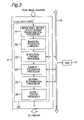
- FIG. 2 is a block diagram that illustrates the basic configuration of the copier in accordance with the first embodiment of the present invention
- FIG. 3 is a block diagram that illustrates the configuration of a pattern-detection processor in the image-data processor of FIG. 2 ;
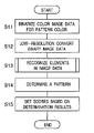
- FIG. 4 is a flowchart of pattern-detection processing in accordance with the first embodiment of the present invention.
- FIG. 5 is a block diagram that illustrates the configuration of an element-recognition processor in the pattern-detection processor in accordance with the first embodiment of the present invention
- FIG. 6 shows the arrangement of the pixels that constitute an ideal element
- FIGS. 7A , 7 B, 7 C and 7 D show various 7 ⁇ 7 pixel-block areas that contain recognition objects identified as element candidates
- FIGS. 8A , 8 B, 8 C and 8 D show various 7 ⁇ 7 pixel-block areas that contain recognition objects not identified as element candidates
- FIGS. 9A , 9 B, 9 C, 9 D, 9 E, 9 F, 9 G and 9 H show examples of reference blocks set in the pixel-block areas containing element candidates of various sizes
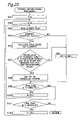
- FIG. 10 is a flowchart of element-recognition processing in accordance with the first embodiment of the present invention.
- FIG. 11 is a block diagram that illustrates an element-recognition processor in the pattern-detection processor in accordance with a second embodiment of the present invention.
- FIG. 12 illustrates the determination conditions for pixel information at opposite vertices in accordance with the second embodiment of the present invention
- FIG. 13 illustrates the determination conditions for pixel information on the outermost lines in accordance with the second embodiment of the present invention
- FIG. 14 illustrates the determination conditions for pixel information on opposite sides on the outermost lines in accordance with the second embodiment of the present invention
- FIG. 15 is a flowchart of element-recognition processing in accordance with the second embodiment of the present invention.
- FIG. 16 is a flowchart of pattern-detection processing in accordance with a third embodiment of the present invention.
- FIG. 17 is a block diagram that illustrates the configuration of an element-recognition processor in the pattern-detection processor in accordance with the third embodiment of the present invention.
- FIG. 18 shows examples of how to set scores for various elements in accordance with the third embodiment of the present invention.
- FIG. 19 is a flowchart of element-detection and score-setting processing in accordance with the third embodiment of the present invention.
- FIG. 20 shows the arrangement of the elements that constitute an ideal pattern
- FIG. 21 shows a pattern composed of elements having set scores and determination results
- FIG. 22 shows another pattern composed of elements having set scores and determination results
- FIG. 23 is a flowchart of specific pattern determination processing in accordance with the third embodiment of the present invention.
- FIG. 1 schematically illustrates a copier in accordance with a first embodiment of the present invention
- FIG. 2 is a block diagram that shows a basic configuration of the copier.
- This copier 1 comprises, as its basic components, an image scanner 4 that reads a manuscript using an optical system to obtain image data, an image-data processor 5 that performs various processing including character-recognizing processing for the image data, a printer 6 that performs printing based on the image data.
- these components are connected, through a data bus 15 , to a CPU 11 that controls the various components built into the copier 1 , a ROM 12 that stores control programs for the CPU 11 , and a RAM 13 that temporarily stores data and programs executed by the CPU 11 for control.
- a CCD 2 of the image scanner 4 optically reads a manuscript on a manuscript table and performs photoelectric transfer.
- a tri-line linear CCD with 3 lines of sensor elements corresponding to three color components, R (red), G (green), and B (blue) is used for the CCD 2 .
- This linear CCD can obtain three colors of light, R, G, and B from the reflected light with one-time scanning, when light is irradiated on a manuscript of the manuscript table.
- the linear CCD can convert each of the three colors of light into an electric signal (analog image data).
- the analog image data obtained by the image scanner 4 is input to the image-data processor 5 to be processed thereby and converted to an output format appropriate for the printer 6 .
- the printer 6 creates a hard copy based on the image data output from the image-data processor 5 .
- the operation of each component during this process is executed by CPU 11 , which stores the programs recorded in ROM 12 in RAM 13 and successively reads them.
- FIG. 3 is a block diagram illustrating the configuration of the pattern-detection processor built into the image-data processor 5 .
- This pattern-detection processor 20 has an image-input section 21 to which digitized image data is input, a low-resolution converting processor 23 that lowers the resolution of the image data, and binarizing processor 22 that performs labeling (binarizing) each density value of the pixels constituting the image data whose resolution has been lowered.
- the image data input to the image-input section 21 is data in which each of R (red), G (green), and B (blue) has density value of 8 bits (256 levels).
- preprocessing of resolution conversion, multiplication transformation and the like may be added, if necessary.
- the binarizing processor 22 determines whether a density value for a given color of each of the pixels constituting the image data is within a predetermined reference range and performs binarizing processing to set the pixel having the density value within the reference range as an ON-pixel. It is noted that an “ON-pixel” is a pixel having the value 1 in binary image data and represents a pixel in which a point exists. This definition is applied hereafter.
- the image data is then input to the resolution-lowering processor 23 to be converted to low-resolution data, by pixel-skipping to be processed later for element-recognition processing.
- the low-resolution image data is temporarily stored in a predetermined memory such as RAM 13 .
- the pattern-detection processor 20 has an element-recognition processor 24 that recognizes the elements that is contained in the image data, and that is part of a specific pattern, a pattern-determination processor 25 that determines a pattern composed of a plurality of elements, and a score-setting processor 26 that gives a score for the determination results.
- the element-recognition processor 24 reads the image data stored in RAM 13 to recognize an element in the image data.
- This “element” represents a partial-image that constitutes part of a pattern and has an empty inside, a predetermined size and color.
- the results obtained by the element-recognition processing are stored again in RAM 13 .
- the pattern-determination processor 25 determines, based on the arrangement of a plurality of elements stored in RAM 13 , whether a specific pattern is composed of these elements.
- the score-setting processor 26 gives a score for the determination results by the pattern-determination processor 25 .
- FIG. 4 is a flowchart of pattern-detection processing by the pattern-detection processor 20 .
- this pattern-detection processing first, the color image data input through the image-input section 21 is binarized for the pattern color (S 11 ). Next, the binary image data is converted to a low-resolution image data (S 12 ). Then, the whole binary image data of low resolution is successively scanned by a filter of m ⁇ n size in which an element can be framed, and elements contained in the image data are recognized (S 13 ). This element-recognition processing is detailed later with reference to FIG. 10 .
- the binary image data is scanned by a filter of a size in which a specific pattern can be framed, and the pattern is recognized based on the arrangement of the recognized elements (S 14 ). Then, the obtained pattern-determination results are evaluated, and a score corresponding to the results are set (S 15 ). The pattern-detection processing is thus finished.
- FIG. 5 is a block diagram that represents the configuration of the element-recognition processor 24 in the pattern-detection processor 20 .
- This element-recognition processor 24 has an element-candidate determiner 31 that evaluates recognition objects in the image data based on predetermined conditions to identify recognition objects satisfying the conditions as element candidates, an element-candidate-size detector 32 that detects the size of the recognition object identified as an element candidate, an OFF-pixel detector 33 that detects OFF-pixels that exist in a reference block within a pixel block area containing the recognition object, which consists of a target pixel and predetermined pixels in its neighborhood, and a final element determiner 34 that determines a final element depending on the determination and detection results by these components.
- the reading and writing of data performed by the element-recognition processor 24 for RAM 13 are controlled by a memory controller 18 .
- a “target pixel” represents a reference pixel that is located at the center or its neighborhood of each pixel-block area, when pixel-block areas in the image data are successively scanned, during the element-recognition processing, by a filter of mxn size in which an element can be framed.
- An “OFF-pixel” is a pixel having value 0 in binary image data, that it is a pixel in which a point does not exit.
- the memory controller 18 derives, during the element-recognition processing, the address on RAM 13 where the binary image data is stored, and successively reads pixel-block areas in the binary image data from RAM 13 .
- These pixel-block areas are rectangular block-areas consisting of mxn pixels with its center being at a target pixel. The size of a pixel-block area is determined based on processing resolution and the size of an ideal element.
- the pixel-block areas read by the memory controller 18 are input to the element-candidate determiner 31 and the OFF-pixel detector 33 .
- the element-candidate determiner 31 evaluates recognition objects in input pixel-block areas based on predetermined conditions to identify recognition objects satisfying the conditions as element candidates.
- the predetermined conditions are that (1) the pixels constituting the outermost lines of a pixel-block area are all OFF-pixels, and that (2) the number of ON-pixels contained in a predetermined area with its center being at a target pixel in the pixel-block area is within a prescribed range.
- an ideal element is a circular image having an empty inside such that, in a 4 ⁇ 4 pixel-block area, ON-pixels are arranged on the upper, lower, left and right sides, and OFF-pixels are arranged at the four corners and the middle 2 ⁇ 2 pixel-block area.
- the pixels indicated by crosshatching are ON-pixels.
- element-candidate determination is performed in a 7 ⁇ 7 pixel-block area. In this case, corresponding to the above conditions (1) and (2), the following conditions are established.
- the pixels constituting the outermost lines of the 7 ⁇ 7 pixel-block area are all OFF-pixels, and the number of ON-pixels contained in a 5 ⁇ 5 pixel-block area with its center being at a target pixel in the 7 ⁇ 7 pixel-block area falls within 6 to 10.
- various recognition objects contained in a 7 ⁇ 7 pixel-block area as shown in FIG. 7A-7D are identified as element candidates. Although these recognition objects differ in shape or size from the ideal element shown in FIG. 6 , they are identified as element candidates, since they satisfy the above conditions (1) and (2).
- various recognition objects contained in a 7 ⁇ 7 pixel-block area as shown in FIG. 8A-8D are not identified as element candidates, since they do not satisfy at least one of the above conditions (1) and (2).
- the pixel-block areas containing recognition objects that have been identified as element candidates by the element-candidate determiner 31 are input to the element-candidate-size detector 32 and the final element determiner 34 at any time.
- the element-candidate-size detector 32 receives a pixel-block area containing a recognition object that has been identified as an element candidate by the element-candidate determiner 31 and detects the size of the recognition object.
- the size of the recognition object is expressed in terms of the size of a rectangular pixel-block (that is, an m ⁇ n pixel-block) in which the recognition object can be framed. For example, if the recognition object is identical to the ideal element shown in FIG. 6 , its size is expressed as a 4 ⁇ 4 pixel-block area.
- the detection results obtained by the element-candidate-size detector 31 are input to the OFF-pixel detector 33 .
- the OFF-pixel detector 33 receives the detection results from the element-candidate-size detector 31 , and based on these detection results, extracts the pixel-block corresponding to the size of the detection object from a pixel-block area input from RAM 13 through memory controller 18 . Next, in the extracted pixel-block, the OFF-pixel detector 33 sets a reference block consisting of a target pixel and the pixels in its predetermined neighborhood and detects OFF-pixels within the reference block. If detecting some OFF-pixels within the reference block, then the OFF-pixel detector 33 determines that the recognition object contained in the pixel-block area is an element having an empty inside.
- FIG. 9A to 9H show examples of set reference blocks in various pixel-blocks extracted as pixel-blocks corresponding to the sizes of recognition objects.
- a pixel marked with an asteroid-shaped symbol represents a target pixel
- an area indicated by crosshatching is a reference block.
- the target pixel is the center pixel, and only the center pixel is set as the reference block. If the target pixel is an OFF-pixel, then the recognition object is identified as an element having a predetermined shape.
- 3 ⁇ 4 pixel-blocks 42 and 43 as shown in FIG. 9B the target pixel is either one of the two pixels within the block, and a reference block consisting of the target pixel and a pixel adjacent to it within the block is set.
- the reference blocks are set on the same area within the block. This situation is similar to the case of 4 ⁇ 3 pixel-blocks 44 and 45 as shown in FIG. 9C .
- the target pixel is the center pixel, and a reference block consisting of the center pixel and the two pixels adjacent to it within the block is set.
- the target pixel is one of the four pixels within the block, and the target pixel, and a reference block consisting of the target pixel and the three pixels adjacent to it within the block is set.
- the target pixel is the center pixel, as in 3 ⁇ 5 pixel-block 46 shown in FIG. 9D , and a reference block consisting of the center pixel and the two pixels adjacent to it within the block is set.
- the target pixel is one of the two pixels in the neighborhood of its center within the block, and a reference block consisting of the target pixel and the five pixels adjacent to it within the block is set. This situation is similar to the case of 5 ⁇ 4 pixel-blocks as shown in FIG. 9H .
- the size of the above reference block varies with the extracted pixel-block area, i.e. the size of the recognition object identified as an element candidate by the element-candidate determiner 31 . This fact means that various kinds of processing resolution and element size can be accommodated.
- the detection results obtained by the OFF-pixel detector 33 are sent to the final element determiner 34 .
- the final element determiner 34 receives determination results from the element-candidate determiner 31 and detection results from the OFF-pixel detector 33 , and based on these results, determines whether the recognition object contained in the pixel-block area is an element.
- the determination results are sent to and stored in RAM 13 through the memory controller 18 .
- the recognition objects that do not all satisfy various conditions are excluded.
- recognition elements more agreeing with the ideal element shown in FIG. 6 are selected, and particularly, elements with empty insides can be recognized with high precision.
- the element-recognition processing as described above is performed after the resolution of the image data is lowered, so that the speedup of processing and saving of used memory can be achieved.
- the elements are approximately circular images having empty insides, so that the shape to be recognized can be identified with relatively simple conditions that are symmetric for the upper and lower sides, left and right sides.
- FIG. 10 is a flowchart of element-recognition processing (S 13 of FIG. 4 ) and shows the processing flow in the element-recognition processor 24 of FIG. 5 .
- the image data is scanned by a filter of the size in which the ideal element shown in FIG. 6 can be framed, and whether the determination conditions as described above are satisfied or not is determined.
- the processing is described for the case where a filter corresponding to a 7 ⁇ 7 pixel-block area is used.
- the binary image data that has been stored after its resolution was lowered is read (S 21 ).
- the start position of scanning by the filter is determined. That is, for the scanning filter, the Y-axis is set at the upper end of the image data (S 22 ), and the X-axis is set at the left end of the image data (S 23 ).
- S 26 the size of the element candidate contained in the 7 ⁇ 7 pixel-block area is examined.
- S 27 it is determined whether OFF-pixels exist within a reference block corresponding to the size of the element candidate and set in the 5 ⁇ 5 pixel-block. If OFF-pixels do not exist, then the element flag is set at “OFF” (S 29 ), and the flow proceeds with S 30 . On the other hand, if OFF-pixels exist, then the flow proceeds with S 28 .
- S 28 the recognition object within pixel-block area is identified as an element having a predetermined shape, since all of the conditions tested in S 24 , S 25 , and S 27 are satisfied. Then, the element flag is set at “ON”, and the flow proceeds with S 30 .
- S 30 it is determined whether the 7 ⁇ 7 pixel-block area that is the recognition object is the last pixel-block area in the X-direction. If the 7 ⁇ 7 pixel-block area is not the last one, then the filter is shifted by one pixel in the X-direction (S 31 ), and the flow returns to S 24 to follow the subsequent steps. On the other hand, if the 7 ⁇ 7 pixel-block area is the last one, then the flow proceeds with S 32 , and whether the 7 ⁇ 7 pixel-block area is the last pixel-block area in the Y-direction is determined.
- the filter is shifted by one pixel in the Y-direction (S 33 ), and the flow returns to S 23 to follow the subsequent steps.
- the 7 ⁇ 7 pixel-block area is the last one, then the element-recognition processing is terminated and the flow returns to the main routine.
- the pattern-detection processor and element-recognition processor are configured as hardware circuits, and execution timing for each processing block is controlled by CPU 11 with programs stored in ROM 12 .
- the pattern-detection processing and element-recognition processing as described above can be performed by means of software processing executed by CPU operations.
- programs including the pattern-detection algorithm and element-recognition algorithm are stored in ROM 12 , and each processing is executed by CPU 11 with these programs.
- these programs can be stored in file form in an external storage medium such as a floppy disk, CD-ROM and the like.
- a pixel-block area can be simultaneously input to the element-candidate determiner 31 , the element-candidate-size detector 31 , and the OFF-pixel detector 33 from RAM 13 , and then, the determination and detection results obtained by the element-candidate determiner 31 and the final element determiner 34 can be individually input to the final element determiner 34 .
- the determination and detection results can be evaluated together to determine whether the recognition object is an element having a predetermined shape.
- FIG. 11 is a block diagram that shows the configuration of an element-recognition processor 60 in a pattern-detection processor in accordance with a second embodiment of the present invention.
- This element-recognition processor 60 has an element-candidate determiner 61 that evaluates recognition objects in image data, based on predetermined conditions, to identify recognition objects satisfying the conditions as “element candidates”, an opposite-vertices determiner 62 that determines pixel information at opposite vertices of a pixel-block area containing the recognition object, a outermost-lines determiner 63 that determines pixel information on the outermost lines of the above pixel-block area, a outermost-line opposite sides determiner 64 that determines pixel information on opposite sides of the outermost lines of the above pixel-block area, and a final element determiner 65 that receives the determination results from these components to perform a final determination for an element.
- the reading and writing of data performed between the element-recognition processor 60 and RAM 13 are controlled by a memory controller 18
- the memory controller 18 derives, during the element-recognition processing, the address of RAM 13 in which the binary image data is stored, and successively reads first pixel-block areas in the binary image data from RAM 13 .
- These first pixel-block areas are rectangular block-areas consisting of m ⁇ n pixels with their center being at target pixels.
- the size of a pixel-block area is determined based on processing resolution and the size of an ideal element.
- the pixel-block areas read by the memory controller 18 are input to the element-candidate determiner 61 .
- the element-candidate determiner 61 evaluates recognition objects in input pixel-block areas based on predetermined conditions to identify recognition objects satisfying the conditions as element candidates.
- the predetermined conditions are that (1) the pixels constituting the outermost lines of a pixel-block area are all OFF-pixels, and that (2) the number of ON-pixels contained in a predetermined area with its center being at a target pixel in the pixel-block area falls within a prescribed range.
- the determination processing is the same as the processing performed by the element-candidate determiner 31 described with reference to FIGS. 6 to 8 in the first embodiment described above, and so, the description is omitted.
- the pixel-block areas containing recognition objects that have been identified as element candidates by the element-candidate determiner 61 are input to the opposite-vertices determiner 62 .
- the opposite-vertices determiner 62 first extracts, from the first pixel-block area containing a recognition object identified as an element candidate by the element-candidate determiner 61 , a second pixel-block area containing the recognition object. For example, in a 7 ⁇ 7 pixel-block area that has been identified as an element candidate, since the outermost lines consist of OFF-pixels only based on the above condition (1), a 5 ⁇ 5 pixel-block area is extracted as the second pixel-block area containing a recognition object. Then, the pixel-block area containing the recognition object is evaluated based on the condition that the number of OFF-pixels in each pixel pair that is located at opposite vertices is less than 2.
- the determination processing performed by the opposite-vertices determiner 62 is explained with reference to FIG. 12 .
- the object to be processed is a 5 ⁇ 5 pixel-block area that contains a recognition object with its center being at a target pixel.
- this 5 ⁇ 5 pixel-block area there exist pixel pairs (A, A′) and (B, B′) located at opposite vertices.
- A+A′and B+B′ are evaluated, where the value for an ON-pixel is 1 and the value for an OFF-pixel is 0.
- A+A′ ⁇ 2, and B+B′ ⁇ 2 the recognition object in the 5 ⁇ 5 pixel-block area is identified as an element.
- recognition objects having two pixels at opposite vertices can be excluded, so that a recognition object agreeing with the ideal element shown in FIG. 6 can be selected.
- the pixel-block areas containing recognition objects that have been identified as element candidates by the opposite-vertices determiner 62 are input to the outermost-lines determiner 63 .
- the outermost-lines determiner 63 determines pixel information on the outermost lines of the second pixel-block area containing a recognition object. That is, the second pixel-block area containing a recognition object is evaluated based on the condition that the number of ON-pixels on the outermost lines is not larger than a predetermined number. This determination process is explained here with reference to FIG. 13 .
- the object to be processed is a 5 ⁇ 5 pixel-block area that contains a recognition object with its center being a target pixel. In this 5 ⁇ 5 pixel-block area, there exist outermost lines E 1 and E 5 in the horizontal direction and Ea and Ee in the vertical direction.
- E 1 , E 5 , Ea and Ee are evaluated, where the value for an ON-pixel is 1 and the value for an OFF-pixel is 0. Then, if E1 ⁇ 4 E5 ⁇ 4 Ea ⁇ 4, and Ee ⁇ 4, then the recognition object within the 5 ⁇ 5 pixel-block area is determined to be an element.
- the pixel-block areas containing recognition objects and determined to be elements by the outermost-lines determiner 63 are input to the outermost-line opposite sides determiner 64 .
- the outermost-line opposite-sides determiner 64 determines pixel information on opposite sides of the outermost lines in the second pixel-block area containing a recognition object.
- the second pixel-block area containing a recognition object is evaluated based on the condition that the number of ON-pixels on each pair of outermost lines that constitute opposite sides is not larger than a predetermined number.
- the determination processing is explained here with reference to FIG. 14 .
- the object to be processed is a 5 ⁇ 5 pixel-block area that contains a recognition object with its center being at a target pixel. In this 5 ⁇ 5 pixel-block area, there exist the outermost line pairs (E 1 , E 5 ) and (Ea, Ee) that constitute opposite sides.
- E 1 +E 5 and Ea+Ee are evaluated, where the value for an ON-pixel is 1 and the value for an OFF-pixel is 0. Then, if E 1 +E 5 ⁇ 5, and Ea+Ee ⁇ 5, then the recognition object in 5 ⁇ 5 pixel-block area is identified as an element.
- the pixel-block areas containing recognition objects identified as elements by the outermost-line opposite sides determiner 64 are input to the outermost-line opposite sides determiner 64 .
- the final element determiner 65 receives pixel-block areas from the outermost-line opposite sides determiner 64 and determines whether the recognition objects contained in the pixel-block areas are elements. The determination results are sent to and stored in RAM 13 through the memory controller 18 .
- the recognition objects that do not all satisfy various conditions are excluded.
- recognition elements more agreeing with the ideal element shown in FIG. 6 are selected, and an element can be recognized with high precision.
- the element-recognition processing as described above is performed after the resolution of the image data is lowered, the speedup of processing and saving of used memory can be achieved.
- the elements are approximately circular images having empty insides, so that the shape to be recognized can be determined with relatively simple conditions that it is symmetric for the upper and lower sides, left and right sides.
- FIG. 15 is a flowchart of element-recognition processing and shows the processing flow in the element-recognition processor 60 of FIG. 11 .
- the image data is scanned by a filter of the size in which the ideal element, for example, shown in FIG. 6 can be framed, and whether the determination conditions as described above are satisfied or not is determined.
- the processing is described for the case where a filter corresponding to a 7 ⁇ 7 pixel-block area is used.
- the binary image data that has been stored after its resolution was lowered is read (S 41 ).
- the start position of scanning by the filter is determined. That is, for the scanning filter, the Y-axis is set at the upper end of the image data (S 42 ), and the X-axis is set at the left end of the image data (S 43 ).
- the recognition object that has satisfied the conditions of both S 44 and S 45 is determined as an “element candidate”, and it is further determined whether the element candidate satisfies the determination conditions as described above with reference to FIGS. 12 to 14 (S 46 to S 48 ).
- S 46 the number of ON-pixels on opposite vertices in the 5 ⁇ 5 pixel-block area is determined. That is, it is determined whether the number of ON-pixels at each pair of opposite vertices is less than 2. If at least one of the numbers is not less than 2, then the element flag is set at OFF (S 50 ), and the flow proceeds with S 51 . On the other hand, if both numbers are less than 2, then the flow proceeds with S 47 .
- the outermost lines in the 5 ⁇ 5 pixel-block area are determined. That is, it is determined whether the number of ON-pixels on each outermost line is not larger than 4. If at least one of the numbers is larger than 4, then the element flag is set at “OFF” (S 50 ), and the flow proceeds with S 51 . On the other hand, if numbers are less than 5, then the flow proceeds with S 48 .
- the numbers of ON-pixels on opposite sides in the outermost lines of the 5 ⁇ 5 pixel-block area are determined. That is, it is determined whether the number of ON-pixels on each pair of opposite sides in the outermost lines of the 5 ⁇ 5 pixel-block area is not larger than 5. If at least one of the numbers is larger than 5, then the element flag is set at “OFF” (S 50 ), and the flow proceeds with S 51 . If both numbers are less than 6, then the flow proceeds with S 49 . In S 49 , the recognition object in the pixel-block area is identified as an element, since all of the conditions tested in S 44 to S 48 are satisfied. Then, the element flag is set at “ON”, and the flow proceeds with S 51 .
- S 51 it is determined whether the 7 ⁇ 7 pixel-block area for a recognition object is the last pixel-block area in the X-direction. If the 7 ⁇ 7 pixel-block area is not the last one, then the filter is shifted by one pixel in the X-direction (S 52 ), and the flow returns to S 44 to follow the subsequent steps. On the other hand, if the 7 ⁇ 7 pixel-block area is the last one, then the flow proceeds with S 53 , and whether the 7 ⁇ 7 pixel-block area is the last pixel-block area in the Y-direction is determined.
- the filter is shifted by one pixel in the Y-direction (S 54 ), and the flow returns to S 43 to follow the subsequent steps.
- the 7 ⁇ 7 pixel-block area is the last one, then the element-recognition processing is terminated and the flow returns to the main routine.
- the pattern-detection processor and element-recognition processor are configured as hardware circuits, and execution timing for each processing block is controlled by CPU 11 with programs stored in ROM 12 .
- the pattern-detection processing and element-recognition processing as described above can be performed by means of software processing executed by CPU operations.
- programs including the pattern-detection algorithm and element-recognition algorithm are stored in ROM 12 , and each processing block is executed by CPU 11 with these programs.
- these programs can be stored in file form in an external storage medium such as a floppy disk, CD-ROM and the like.
- a pixel-block area can be simultaneously input to each component (the element-candidate determiner 61 , the opposite-vertices determiner 62 , the outermost-lines determiner 63 , and the outermost-line opposite sides determiner 64 ) from RAM 13 , and then, the determination and detection results obtained by these components can be individually input to the final element determiner 65 .
- the determination and detection results can be evaluated together to determine whether a recognition object is an element having a predetermined shape.
- FIG. 16 is a flowchart of pattern-detection processing by a pattern-detection processor in accordance with a third embodiment of the present invention.
- this pattern-detection processing first, the color image data input from an image-input section is binarized for the pattern color (S 61 ). Next, the binary image data is converted to low-resolution image data (S 62 ). Then, the whole binary image data of which resolution has been lowered is successively scanned by a filter of m ⁇ n size in which an element can be framed, and elements contained in the image data are recognized and the score is provided for each element (S 63 ).
- the binary image data is scanned by a filter of a size in which a specific pattern is framed, and the pattern is recognized based on the arrangement of the recognized element and the score of the element given in S 63 (S 64 ). Then, the obtained pattern determination results are evaluated, and a score corresponding to the results are set (S 65 ). The pattern-detection processing is thus finished.
- the element-recognition and score-setting processing (S 63 ) and the pattern-determination processing (S 64 ) are described in detail later with reference to FIGS. 19 and 23 .
- FIG. 17 is a block diagram that illustrates the configuration of the element-recognition processor 70 in accordance with the third embodiment of the present invention.
- This element-recognition processor 70 has an element-candidate determiner 71 that evaluates recognition objects in the image data, based on predetermined conditions, to identify a recognition object satisfying the conditions as an “element candidate”, an element-score setter 72 that sets a score for each element candidate, based on similarity between the element candidate and a reference element having a predetermined size and shape, and a final-element determiner 74 that receives the determination results from these components to perform a final determination for an element.
- the reading and writing of data performed between the element-recognition processor 70 and RAM 13 are controlled by a memory controller 18 .
- the memory controller 18 derives, during the element-recognition processing, the address of RAM 13 where the binary image data is stored, and successively reads pixel-block areas in the binary image data from RAM 13 .
- These pixel-block areas are rectangular block-areas consisting of m ⁇ n pixels with its center being at an target pixel. The size of a pixel-block area is determined based on processing resolution and the size of an ideal element.
- the pixel-block areas read by the memory controller 18 are input to the element-candidate determiner 71 .
- the element-candidate determiner 71 evaluates recognition objects in input pixel-block areas, based on predetermined conditions, to identify recognition objects satisfying the conditions as element candidates.
- the predetermined conditions are that (1) the pixels constituting the outermost lines of a pixel-block area are all OFF-pixels, and that (2) the number of ON-pixels contained in a predetermined area with its center being at a target pixel in the pixel-block area falls within a prescribed range.
- the determination processing is the same as the processing performed by the element-candidate determiner 31 in the first embodiment and described with reference to FIGS. 6 to 8 . Therefore the explanation is omitted.
- the pixel-block areas containing recognition objects that have been identified as element candidates by the element-candidate determiner 71 are input to the element-score setter 72 and the final element determiner 73 .
- the element-score setter 72 sets a score for each element, based on similarity between the element contained in the pixel-block area input from the element-candidate determiner 71 and a reference element that is identical to an ideal element as shown in FIG. 6 .
- the reference element is stored in a predetermined memory, e.g. ROM 12 , and can be read at any time during the score setting.
- FIG. 18 shows various elements that have been scored based on the similarity to the reference element.
- the various elements are classified into shapes, and as a shape is more similar to the reference element, it gains a higher score. That is, if the shape is the same as that of the reference element, then the score 100 is set. If only one pixel of the shape is lacking, then the score 90 is set. If two pixels of the shape are lacking in total on opposite sides or adjacent edges, then the score 80 is set. If one of sides is lacking, then the score 70 is set.
- score-setting processing is not limited to this procedure, and other various manners can be used as long as the scores can be provided for similarity to the reference elements.
- the scoring results provided by the element-score setter 72 are input to the final element determiner 73 at any time.
- the final element determiner 73 receives pixel-block areas from the element-candidate determiner 71 and determines whether recognition objects contained in the pixel-block areas are elements.
- the final element determiner 73 also receives scoring results from the element-score setter 72 and relates them to corresponding elements.
- the determination results and the element scores are sent to RAM 13 through the memory controller 18 and stored therein.
- FIG. 19 is a flowchart of element-recognition and score-setting processing (S 63 of FIG. 16 ) and shows the processing flow in the element-recognition processor 70 of FIG. 17 .
- this processing for example, the image data is scanned by a filter of the size in which the ideal element as shown in FIG. 6 can be framed, and whether the determination conditions described above are satisfied or not is determined.
- the processing is described for the case where a filter corresponding to a 7 ⁇ 7 pixel-block area is used.
- the binary image data that has been stored after its resolution was lowered is read (S 71 ).
- the start position of scanning by the filter is determined. That is, for the scanning filter, the Y-axis is set at the upper end of the image data (S 72 ), and the X-axis is set at the left end of the image data (S 73 ).
- the recognition object that has satisfied the conditions of both S 74 and S 75 is determined as an element candidate, and the element flag is set at “ON”.
- S 77 similarity of shapes between the element and the reference element is evaluated and a score is set for the element.
- S 80 it is determined whether the 7 ⁇ 7 pixel-block area that is a recognition object is the last pixel-block area in the X-direction. If the 7 ⁇ 7 pixel-block area is not the last one, then the filter is shifted by one pixel in the X-direction (S 81 ), and the flow returns to S 74 to follow the subsequent steps.
- the flow proceeds with S 82 , and whether the 7 ⁇ 7 pixel-block area is the last pixel-block area in the Y-direction. If the 7 ⁇ 7 pixel-block area is not the last one, then the filter is shifted by one pixel in the Y-direction (S 83 ), and the flow returns to S 73 to follow the subsequent steps. On the other hand, if the 7 ⁇ 7 pixel-block area is the last one, then the score-setting processing is terminated and the flow returns to the main routine.
- a score is set for each element, based on similarity between the element and the reference element, so that recognition precision for each element is relatively evaluated.
- an ideal pattern be a pattern that is composed of seven elements arranged in such a way as shown in FIG. 20 , and the case where two patterns shown in FIGS. 21 and 22 have been recognized is considered.
- the arrangement of the elements agrees with that of the ideal pattern.
- the shapes of the elements have some irregularities with the total score 520. In this case, the pattern is identified as the specific pattern.
- the pattern shown in FIG. 22 one of the seven elements (lower right element) is smeared and corrupted, so that the arrangement does not agree with that of the ideal pattern.
- the shapes of the other six elements are the same as the reference element, so that the total score for the elements is 600. In this case, the pattern is identified as the specific pattern.
- FIG. 23 is a flowchart of the pattern-determination processing described above and shows the processing flow in a pattern-determination processor in accordance with the third embodiment of the present invention.
- image data is scanned by a filter in which an ideal pattern as shown in FIG. 20 , for example, can be framed. Then, elements contained and recognized in a pixel-block area corresponding to the filter are considered.
- the start position of scanning by the filter is determined. That is, for the scanning filter, the Y-axis is set at the upper end of the image data (S 91 ), and the X-axis is set at the left end of the image data (S 92 ).
- the element flag set for each element recognized in a flame is read (S 93 ), and whether the elements constitute the pattern is determined, depending on whether the fitness for pattern matching is not less than a predetermined threshold value (S 94 ). If the elements do not constitute the pattern, then the score 0 is set (S 96 ), and flow proceeds with S 99 . If the elements constitute the pattern, then the total score for the elements is calculated (S 95 ).
- S 97 it is determined whether the sum of the score representing the fitness of the arrangement of the elements to the arrangement of an ideal pattern and the total score for the elements is not less than a predetermined value. If the sum is less than the predetermined value, then it is determined that the elements do not constitute the pattern, so that the score 0 is set (S 96 ), and the flow proceeds with S 99 . On the other hand, if the sum is not less than the predetermined value, then it is determined that the elements constitute the specific pattern (S 98 ), and the flow proceeds with S 99 .
- S 99 it is determined whether the block area to be determined is the last pixel-block area in the X-direction. If the block area is not the last one, then the filter is shifted by one pixel in the X-direction (S 100 ), and the flow returns to S 93 to follow the subsequent steps. On the other hand, if the block area is the last one, then the flow proceeds with S 101 , and it is determined whether the block area is the last pixel-block area in the Y-direction. If the block area is not the last one, then the filter is shifted by one pixel in the Y-direction (S 102 ), and the flow returns to S 92 to follow the subsequent steps. On the other hand, if the block area is the last one, then the pattern-determination processing is terminated and the flow returns to the main routine.
- the arrangement of the elements contained in a predetermined pixel-block area is evaluated as well as the scores set for the individual elements by the element-recognition and score-setting processing, and the recognition precision for elements contained in the pixel-block is synthetically determined. Therefore, a specific pattern can be detected with high precision.
- the pattern-detection processor and element-recognition processor are configured as hardware circuits, and execution timing for each processing block is controlled by CPU 11 with programs stored in ROM 12 .
- the pattern-detection and element-recognition processing as described above can be performed as software processing executed by CPU operations.
- programs including the pattern detecting algorithm and element-recognition algorithm are stored in ROM 12 , and each processing block is executed by CPU 11 with these programs.
- these programs can be stored in file form in an external storage medium such as a floppy disk, CD-ROM and the like.
- the hardware configuration of the element-recognition processor 70 described with reference to FIG. 17 can be modified.
- a pixel-block area can be simultaneously input to each component (the element-candidate determiner 71 and the element-score setter 72 ) from RAM 13 , and then, the determination results and element scores can be individually input to the final element determiner 73 .
- the determination results and element scores can be evaluated together to provide a score representing similarity to the specific pattern for the recognition object that has been determined as an element.
Abstract
Description
A+A′<2, and
B+B′<2,
then the recognition object in the 5×5 pixel-block area is identified as an element. According to this determination processing, recognition objects having two pixels at opposite vertices can be excluded, so that a recognition object agreeing with the ideal element shown in
E1≦4
E5≦4
Ea≦4, and
Ee≦4,
then the recognition object within the 5×5 pixel-block area is determined to be an element.
E1+E5≦5, and
Ea+Ee≦5,
then the recognition object in 5×5 pixel-block area is identified as an element.
Claims (11)
Priority Applications (1)
| Application Number | Priority Date | Filing Date | Title |
|---|---|---|---|
| US10/976,002 US7263228B2 (en) | 2000-04-26 | 2004-10-29 | Apparatus and method for detecting a pattern |
Applications Claiming Priority (4)
| Application Number | Priority Date | Filing Date | Title |
|---|---|---|---|
| JP2000-125947 | 2000-04-26 | ||
| JP2000125949A JP4218179B2 (en) | 2000-04-26 | 2000-04-26 | Pattern detection apparatus and method |
| JP2000125947A JP4206604B2 (en) | 2000-04-26 | 2000-04-26 | Pattern detection apparatus and method |
| JP2000125948A JP4254008B2 (en) | 2000-04-26 | 2000-04-26 | Pattern detection apparatus and method |
Related Child Applications (1)
| Application Number | Title | Priority Date | Filing Date |
|---|---|---|---|
| US10/976,002 Division US7263228B2 (en) | 2000-04-26 | 2004-10-29 | Apparatus and method for detecting a pattern |
Publications (2)
| Publication Number | Publication Date |
|---|---|
| US20010036317A1 US20010036317A1 (en) | 2001-11-01 |
| US7123768B2 true US7123768B2 (en) | 2006-10-17 |
Family
ID=27343206
Family Applications (2)
| Application Number | Title | Priority Date | Filing Date |
|---|---|---|---|
| US09/841,039 Expired - Fee Related US7123768B2 (en) | 2000-04-26 | 2001-04-25 | Apparatus and method for detecting a pattern |
| US10/976,002 Expired - Fee Related US7263228B2 (en) | 2000-04-26 | 2004-10-29 | Apparatus and method for detecting a pattern |
Family Applications After (1)
| Application Number | Title | Priority Date | Filing Date |
|---|---|---|---|
| US10/976,002 Expired - Fee Related US7263228B2 (en) | 2000-04-26 | 2004-10-29 | Apparatus and method for detecting a pattern |
Country Status (1)
| Country | Link |
|---|---|
| US (2) | US7123768B2 (en) |
Cited By (6)
| Publication number | Priority date | Publication date | Assignee | Title |
|---|---|---|---|---|
| US20030228066A1 (en) * | 2002-06-11 | 2003-12-11 | Nec Corporation | Image data processing unit for use in a visual inspection device |
| US20040190017A1 (en) * | 2003-03-28 | 2004-09-30 | Anson Bryce L. | Rendering a printing device pixel map |
| US20060279749A1 (en) * | 2005-06-10 | 2006-12-14 | Xerox Corporation | Super resolution encoding |
| US20070071358A1 (en) * | 2005-09-27 | 2007-03-29 | Aten International Co., Ltd. | Digital Image Data Processing Apparatus |
| US8571307B2 (en) | 2010-11-16 | 2013-10-29 | Hand Held Products, Inc. | Method and system operative to process monochrome image data |
| US8600158B2 (en) | 2010-11-16 | 2013-12-03 | Hand Held Products, Inc. | Method and system operative to process color image data |
Families Citing this family (11)
| Publication number | Priority date | Publication date | Assignee | Title |
|---|---|---|---|---|
| US7218417B2 (en) * | 2003-01-30 | 2007-05-15 | Xerox Corporation | Resolution conversion using a morphological partial pixel mapping (MPPM) approach |
| US7852362B2 (en) * | 2005-07-15 | 2010-12-14 | Ricoh Company, Limited | Image writing device using digital light-emitting elements |
| TWI337331B (en) * | 2007-07-20 | 2011-02-11 | Asustek Comp Inc | Method for finding specific pattern and method for compensating image offset |
| AT510837B1 (en) | 2011-07-27 | 2012-07-15 | Helmut Dr Buchberger | INHALATORKOMPONENTE |
| GB2504076A (en) | 2012-07-16 | 2014-01-22 | Nicoventures Holdings Ltd | Electronic smoking device |
| GB2528673B (en) | 2014-07-25 | 2020-07-01 | Nicoventures Holdings Ltd | Aerosol provision system |
| GB2533135B (en) | 2014-12-11 | 2020-11-11 | Nicoventures Holdings Ltd | Aerosol provision systems |
| KR102369156B1 (en) | 2016-04-27 | 2022-02-28 | 니코벤처스 트레이딩 리미티드 | Electronic aerosol delivery system and vaporizer for electronic aerosol delivery system |
| CN110895813A (en) * | 2019-01-21 | 2020-03-20 | 杨鹏 | Resident building data extraction mechanism |
| US11800056B2 (en) | 2021-02-11 | 2023-10-24 | Logitech Europe S.A. | Smart webcam system |
| US11800048B2 (en) | 2021-02-24 | 2023-10-24 | Logitech Europe S.A. | Image generating system with background replacement or modification capabilities |
Citations (25)
| Publication number | Priority date | Publication date | Assignee | Title |
|---|---|---|---|---|
| US4395698A (en) * | 1980-08-15 | 1983-07-26 | Environmental Research Institute Of Michigan | Neighborhood transformation logic circuitry for an image analyzer system |
| US4435836A (en) * | 1981-10-15 | 1984-03-06 | Bell Telephone Laboratories, Incorporated | Technique for extracting features from images |
| US4644585A (en) * | 1985-02-11 | 1987-02-17 | Environmental Research Institute Of Michigan | Method and apparatus for automatic shape recognition |
| US4700401A (en) * | 1983-02-28 | 1987-10-13 | Dest Corporation | Method and apparatus for character recognition employing a dead-band correlator |
| US4724543A (en) * | 1985-09-10 | 1988-02-09 | Beckman Research Institute, City Of Hope | Method and apparatus for automatic digital image analysis |
| US4821133A (en) * | 1987-02-17 | 1989-04-11 | Magnetic Peripherals, Inc. | Bottleneck magnetoresistive element |
| US4914709A (en) * | 1989-06-02 | 1990-04-03 | Eastman Kodak Company | Method for identifying unrecognizable characters in optical character recognition machines |
| US4941192A (en) * | 1987-04-20 | 1990-07-10 | Hitachi, Ltd. | Method and apparatus for recognizing pattern of gray level image |
| US5048109A (en) * | 1989-12-08 | 1991-09-10 | Xerox Corporation | Detection of highlighted regions |
| US5091966A (en) * | 1990-07-31 | 1992-02-25 | Xerox Corporation | Adaptive scaling for decoding spatially periodic self-clocking glyph shape codes |
| US5128525A (en) * | 1990-07-31 | 1992-07-07 | Xerox Corporation | Convolution filtering for decoding self-clocking glyph shape codes |
| US5168147A (en) * | 1990-07-31 | 1992-12-01 | Xerox Corporation | Binary image processing for decoding self-clocking glyph shape codes |
| US5181255A (en) * | 1990-12-13 | 1993-01-19 | Xerox Corporation | Segmentation of handwriting and machine printed text |
| US5201011A (en) * | 1991-11-19 | 1993-04-06 | Xerox Corporation | Method and apparatus for image hand markup detection using morphological techniques |
| US5202933A (en) * | 1989-12-08 | 1993-04-13 | Xerox Corporation | Segmentation of text and graphics |
| US5224179A (en) * | 1988-12-20 | 1993-06-29 | At&T Bell Laboratories | Image skeletonization method |
| US5390003A (en) | 1992-11-30 | 1995-02-14 | Minolta Camera Kabushiki Kaisha | Copying system for preventing copying of copy-prohibited images |
| US5579445A (en) * | 1993-12-17 | 1996-11-26 | Xerox Corporation | Image resolution conversion method that employs statistically generated multiple morphological filters |
| US5590220A (en) * | 1992-08-12 | 1996-12-31 | International Business Machines Corporation | Bending point extraction method for optical character recognition system |
| US5600736A (en) * | 1993-12-02 | 1997-02-04 | Nippon Telegraph And Telephone Corporation | Image pattern identification/recognition method |
| JPH1153539A (en) | 1997-08-04 | 1999-02-26 | Ricoh Co Ltd | Circular pattern discriminating method and storage medium |
| US5898795A (en) * | 1995-12-08 | 1999-04-27 | Ricoh Company, Ltd. | Character recognition method using a method for deleting ruled lines |
| US6272244B1 (en) * | 1997-08-06 | 2001-08-07 | Nippon Telegraph And Telephone Corporation | Methods for extraction and recognition of pattern in an image method for image abnormality judging, and memory medium with image processing programs |
| US6347156B1 (en) * | 1998-05-27 | 2002-02-12 | Fujitsu Limited | Device, method and storage medium for recognizing a document image |
| US6636635B2 (en) | 1995-11-01 | 2003-10-21 | Canon Kabushiki Kaisha | Object extraction method, and image sensing apparatus using the method |
Family Cites Families (4)
| Publication number | Priority date | Publication date | Assignee | Title |
|---|---|---|---|---|
| US4567610A (en) * | 1982-07-22 | 1986-01-28 | Wayland Research Inc. | Method of and apparatus for pattern recognition |
| US4821333A (en) * | 1986-08-22 | 1989-04-11 | Environmental Research Inst. Of Michigan | Machine learning procedures for generating image domain feature detector structuring elements |
| JP3088010B2 (en) * | 1990-05-25 | 2000-09-18 | 株式会社リコー | Line drawing separation method and apparatus |
| DE69232493T2 (en) * | 1991-10-21 | 2003-01-09 | Canon Kk | Method and device for character recognition |
-
2001
- 2001-04-25 US US09/841,039 patent/US7123768B2/en not_active Expired - Fee Related
-
2004
- 2004-10-29 US US10/976,002 patent/US7263228B2/en not_active Expired - Fee Related
Patent Citations (25)
| Publication number | Priority date | Publication date | Assignee | Title |
|---|---|---|---|---|
| US4395698A (en) * | 1980-08-15 | 1983-07-26 | Environmental Research Institute Of Michigan | Neighborhood transformation logic circuitry for an image analyzer system |
| US4435836A (en) * | 1981-10-15 | 1984-03-06 | Bell Telephone Laboratories, Incorporated | Technique for extracting features from images |
| US4700401A (en) * | 1983-02-28 | 1987-10-13 | Dest Corporation | Method and apparatus for character recognition employing a dead-band correlator |
| US4644585A (en) * | 1985-02-11 | 1987-02-17 | Environmental Research Institute Of Michigan | Method and apparatus for automatic shape recognition |
| US4724543A (en) * | 1985-09-10 | 1988-02-09 | Beckman Research Institute, City Of Hope | Method and apparatus for automatic digital image analysis |
| US4821133A (en) * | 1987-02-17 | 1989-04-11 | Magnetic Peripherals, Inc. | Bottleneck magnetoresistive element |
| US4941192A (en) * | 1987-04-20 | 1990-07-10 | Hitachi, Ltd. | Method and apparatus for recognizing pattern of gray level image |
| US5224179A (en) * | 1988-12-20 | 1993-06-29 | At&T Bell Laboratories | Image skeletonization method |
| US4914709A (en) * | 1989-06-02 | 1990-04-03 | Eastman Kodak Company | Method for identifying unrecognizable characters in optical character recognition machines |
| US5048109A (en) * | 1989-12-08 | 1991-09-10 | Xerox Corporation | Detection of highlighted regions |
| US5202933A (en) * | 1989-12-08 | 1993-04-13 | Xerox Corporation | Segmentation of text and graphics |
| US5091966A (en) * | 1990-07-31 | 1992-02-25 | Xerox Corporation | Adaptive scaling for decoding spatially periodic self-clocking glyph shape codes |
| US5128525A (en) * | 1990-07-31 | 1992-07-07 | Xerox Corporation | Convolution filtering for decoding self-clocking glyph shape codes |
| US5168147A (en) * | 1990-07-31 | 1992-12-01 | Xerox Corporation | Binary image processing for decoding self-clocking glyph shape codes |
| US5181255A (en) * | 1990-12-13 | 1993-01-19 | Xerox Corporation | Segmentation of handwriting and machine printed text |
| US5201011A (en) * | 1991-11-19 | 1993-04-06 | Xerox Corporation | Method and apparatus for image hand markup detection using morphological techniques |
| US5590220A (en) * | 1992-08-12 | 1996-12-31 | International Business Machines Corporation | Bending point extraction method for optical character recognition system |
| US5390003A (en) | 1992-11-30 | 1995-02-14 | Minolta Camera Kabushiki Kaisha | Copying system for preventing copying of copy-prohibited images |
| US5600736A (en) * | 1993-12-02 | 1997-02-04 | Nippon Telegraph And Telephone Corporation | Image pattern identification/recognition method |
| US5579445A (en) * | 1993-12-17 | 1996-11-26 | Xerox Corporation | Image resolution conversion method that employs statistically generated multiple morphological filters |
| US6636635B2 (en) | 1995-11-01 | 2003-10-21 | Canon Kabushiki Kaisha | Object extraction method, and image sensing apparatus using the method |
| US5898795A (en) * | 1995-12-08 | 1999-04-27 | Ricoh Company, Ltd. | Character recognition method using a method for deleting ruled lines |
| JPH1153539A (en) | 1997-08-04 | 1999-02-26 | Ricoh Co Ltd | Circular pattern discriminating method and storage medium |
| US6272244B1 (en) * | 1997-08-06 | 2001-08-07 | Nippon Telegraph And Telephone Corporation | Methods for extraction and recognition of pattern in an image method for image abnormality judging, and memory medium with image processing programs |
| US6347156B1 (en) * | 1998-05-27 | 2002-02-12 | Fujitsu Limited | Device, method and storage medium for recognizing a document image |
Cited By (10)
| Publication number | Priority date | Publication date | Assignee | Title |
|---|---|---|---|---|
| US20030228066A1 (en) * | 2002-06-11 | 2003-12-11 | Nec Corporation | Image data processing unit for use in a visual inspection device |
| US20040190017A1 (en) * | 2003-03-28 | 2004-09-30 | Anson Bryce L. | Rendering a printing device pixel map |
| US7333238B2 (en) * | 2003-03-28 | 2008-02-19 | Hewlett-Packard Development Company, L.P. | Rendering a printing device pixel map |
| US20060279749A1 (en) * | 2005-06-10 | 2006-12-14 | Xerox Corporation | Super resolution encoding |
| US7636480B2 (en) * | 2005-06-10 | 2009-12-22 | Xerox Corporation | Super resolution encoding |
| US20070071358A1 (en) * | 2005-09-27 | 2007-03-29 | Aten International Co., Ltd. | Digital Image Data Processing Apparatus |
| US7742661B2 (en) * | 2005-09-27 | 2010-06-22 | Aten International Co., Ltd. | Digital image data processing apparatus |
| US8571307B2 (en) | 2010-11-16 | 2013-10-29 | Hand Held Products, Inc. | Method and system operative to process monochrome image data |
| US8600158B2 (en) | 2010-11-16 | 2013-12-03 | Hand Held Products, Inc. | Method and system operative to process color image data |
| US8849019B2 (en) | 2010-11-16 | 2014-09-30 | Hand Held Products, Inc. | Method and system operative to process color image data |
Also Published As
| Publication number | Publication date |
|---|---|
| US20010036317A1 (en) | 2001-11-01 |
| US7263228B2 (en) | 2007-08-28 |
| US20050089228A1 (en) | 2005-04-28 |
Similar Documents
| Publication | Publication Date | Title |
|---|---|---|
| US7123768B2 (en) | Apparatus and method for detecting a pattern | |
| EP1456816B1 (en) | Apparatus and method for recognizing code | |
| JP3883696B2 (en) | Method for scanning and detecting multiple photos and removing artificial edges | |
| JP4065460B2 (en) | Image processing method and apparatus | |
| US9158986B2 (en) | Character segmentation device and character segmentation method | |
| US8768052B2 (en) | Image processing apparatus, image processing method, and non-transitory computer readable medium | |
| JP5507134B2 (en) | Two-dimensional code reading method, two-dimensional code recognition method, and two-dimensional code reading apparatus | |
| JPH0850633A (en) | Character recognition device | |
| JPH0869505A (en) | Image processing system | |
| JPH0863583A (en) | Device and method for storing and retrieving document | |
| JP2002133426A (en) | Ruled line extracting device for extracting ruled line from multiple image | |
| JPH0877339A (en) | Image processor | |
| JP5337563B2 (en) | Form recognition method and apparatus | |
| US20020051573A1 (en) | Two-dimensional code extracting method | |
| JPH0418351B2 (en) | ||
| JP4132766B2 (en) | Image processing apparatus and method | |
| US6983071B2 (en) | Character segmentation device, character segmentation method used thereby, and program therefor | |
| JP3268552B2 (en) | Area extraction method, destination area extraction method, destination area extraction apparatus, and image processing apparatus | |
| JPH08123901A (en) | Character extraction device and character recognition device using this device | |
| JP4206604B2 (en) | Pattern detection apparatus and method | |
| JP4254008B2 (en) | Pattern detection apparatus and method | |
| JP2000251010A (en) | Document readout method | |
| JP4218179B2 (en) | Pattern detection apparatus and method | |
| JP3253201B2 (en) | Image processing device and image type determination method | |
| JP3061899B2 (en) | Inspection equipment for printed matter |
Legal Events
| Date | Code | Title | Description |
|---|---|---|---|
| AS | Assignment |
Owner name: MINOLTA CO., LTD., JAPAN Free format text: ASSIGNMENT OF ASSIGNORS INTEREST;ASSIGNOR:MORI, TOSHIHIRO;REEL/FRAME:011733/0969 Effective date: 20010413 |
|
| FEPP | Fee payment procedure |
Free format text: PAYOR NUMBER ASSIGNED (ORIGINAL EVENT CODE: ASPN); ENTITY STATUS OF PATENT OWNER: LARGE ENTITY |
|
| FPAY | Fee payment |
Year of fee payment: 4 |
|
| FPAY | Fee payment |
Year of fee payment: 8 |
|
| FEPP | Fee payment procedure |
Free format text: MAINTENANCE FEE REMINDER MAILED (ORIGINAL EVENT CODE: REM.) |
|
| LAPS | Lapse for failure to pay maintenance fees |
Free format text: PATENT EXPIRED FOR FAILURE TO PAY MAINTENANCE FEES (ORIGINAL EVENT CODE: EXP.); ENTITY STATUS OF PATENT OWNER: LARGE ENTITY |
|
| STCH | Information on status: patent discontinuation |
Free format text: PATENT EXPIRED DUE TO NONPAYMENT OF MAINTENANCE FEES UNDER 37 CFR 1.362 |
|
| FP | Lapsed due to failure to pay maintenance fee |
Effective date: 20181017 |