US7104449B2 - Method and apparatus for patterning cards, instruments and documents - Google Patents
Method and apparatus for patterning cards, instruments and documents Download PDFInfo
- Publication number
- US7104449B2 US7104449B2 US09/745,512 US74551200A US7104449B2 US 7104449 B2 US7104449 B2 US 7104449B2 US 74551200 A US74551200 A US 74551200A US 7104449 B2 US7104449 B2 US 7104449B2
- Authority
- US
- United States
- Prior art keywords
- region
- card
- pattern
- disc
- instrument
- Prior art date
- Legal status (The legal status is an assumption and is not a legal conclusion. Google has not performed a legal analysis and makes no representation as to the accuracy of the status listed.)
- Expired - Fee Related, expires
Links
- 238000000034 method Methods 0.000 title claims description 20
- 238000000059 patterning Methods 0.000 title description 3
- 230000003287 optical effect Effects 0.000 claims abstract description 55
- 238000013500 data storage Methods 0.000 claims abstract description 18
- 239000000835 fiber Substances 0.000 claims description 29
- 230000004044 response Effects 0.000 claims description 10
- 230000003595 spectral effect Effects 0.000 claims description 7
- 238000003860 storage Methods 0.000 claims description 7
- 238000005530 etching Methods 0.000 claims 4
- 239000013307 optical fiber Substances 0.000 abstract description 29
- 238000010329 laser etching Methods 0.000 abstract description 3
- 239000000463 material Substances 0.000 description 17
- 238000005286 illumination Methods 0.000 description 6
- 238000010586 diagram Methods 0.000 description 5
- 238000003780 insertion Methods 0.000 description 5
- 230000037431 insertion Effects 0.000 description 5
- 239000003086 colorant Substances 0.000 description 3
- 238000005516 engineering process Methods 0.000 description 3
- 239000000758 substrate Substances 0.000 description 3
- 238000010200 validation analysis Methods 0.000 description 3
- NIXOWILDQLNWCW-UHFFFAOYSA-N acrylic acid group Chemical group C(C=C)(=O)O NIXOWILDQLNWCW-UHFFFAOYSA-N 0.000 description 2
- 244000309464 bull Species 0.000 description 2
- 230000001419 dependent effect Effects 0.000 description 2
- 238000001514 detection method Methods 0.000 description 2
- 230000002708 enhancing effect Effects 0.000 description 2
- 230000006870 function Effects 0.000 description 2
- 238000004519 manufacturing process Methods 0.000 description 2
- 239000004065 semiconductor Substances 0.000 description 2
- 230000003213 activating effect Effects 0.000 description 1
- 229910052782 aluminium Inorganic materials 0.000 description 1
- -1 aluminum compound Chemical class 0.000 description 1
- XTKDAFGWCDAMPY-UHFFFAOYSA-N azaperone Chemical compound C1=CC(F)=CC=C1C(=O)CCCN1CCN(C=2N=CC=CC=2)CC1 XTKDAFGWCDAMPY-UHFFFAOYSA-N 0.000 description 1
- 230000015572 biosynthetic process Effects 0.000 description 1
- 239000011248 coating agent Substances 0.000 description 1
- 238000000576 coating method Methods 0.000 description 1
- 238000010276 construction Methods 0.000 description 1
- 238000005520 cutting process Methods 0.000 description 1
- 238000003384 imaging method Methods 0.000 description 1
- 238000007373 indentation Methods 0.000 description 1
- 230000002452 interceptive effect Effects 0.000 description 1
- 239000004033 plastic Substances 0.000 description 1
- 238000009877 rendering Methods 0.000 description 1
- 238000001228 spectrum Methods 0.000 description 1
- 239000012780 transparent material Substances 0.000 description 1
Images


Classifications
-
- G—PHYSICS
- G11—INFORMATION STORAGE
- G11B—INFORMATION STORAGE BASED ON RELATIVE MOVEMENT BETWEEN RECORD CARRIER AND TRANSDUCER
- G11B23/00—Record carriers not specific to the method of recording or reproducing; Accessories, e.g. containers, specially adapted for co-operation with the recording or reproducing apparatus ; Intermediate mediums; Apparatus or processes specially adapted for their manufacture
- G11B23/28—Indicating or preventing prior or unauthorised use, e.g. cassettes with sealing or locking means, write-protect devices for discs
- G11B23/281—Indicating or preventing prior or unauthorised use, e.g. cassettes with sealing or locking means, write-protect devices for discs by changing the physical properties of the record carrier
-
- G—PHYSICS
- G06—COMPUTING; CALCULATING OR COUNTING
- G06K—GRAPHICAL DATA READING; PRESENTATION OF DATA; RECORD CARRIERS; HANDLING RECORD CARRIERS
- G06K19/00—Record carriers for use with machines and with at least a part designed to carry digital markings
- G06K19/04—Record carriers for use with machines and with at least a part designed to carry digital markings characterised by the shape
- G06K19/041—Constructional details
- G06K19/042—Constructional details the record carrier having a form factor of a credit card and including a small sized disc, e.g. a CD or DVD
- G06K19/045—Constructional details the record carrier having a form factor of a credit card and including a small sized disc, e.g. a CD or DVD the record carrier being of the non-contact type, e.g. RFID, and being specially adapted for attachment to a disc, e.g. a CD or DVD
-
- G—PHYSICS
- G06—COMPUTING; CALCULATING OR COUNTING
- G06K—GRAPHICAL DATA READING; PRESENTATION OF DATA; RECORD CARRIERS; HANDLING RECORD CARRIERS
- G06K19/00—Record carriers for use with machines and with at least a part designed to carry digital markings
- G06K19/06—Record carriers for use with machines and with at least a part designed to carry digital markings characterised by the kind of the digital marking, e.g. shape, nature, code
- G06K19/06009—Record carriers for use with machines and with at least a part designed to carry digital markings characterised by the kind of the digital marking, e.g. shape, nature, code with optically detectable marking
- G06K19/06046—Constructional details
-
- G—PHYSICS
- G06—COMPUTING; CALCULATING OR COUNTING
- G06K—GRAPHICAL DATA READING; PRESENTATION OF DATA; RECORD CARRIERS; HANDLING RECORD CARRIERS
- G06K19/00—Record carriers for use with machines and with at least a part designed to carry digital markings
- G06K19/06—Record carriers for use with machines and with at least a part designed to carry digital markings characterised by the kind of the digital marking, e.g. shape, nature, code
- G06K19/08—Record carriers for use with machines and with at least a part designed to carry digital markings characterised by the kind of the digital marking, e.g. shape, nature, code using markings of different kinds or more than one marking of the same kind in the same record carrier, e.g. one marking being sensed by optical and the other by magnetic means
- G06K19/083—Constructional details
- G06K19/086—Constructional details with markings consisting of randomly placed or oriented elements, the randomness of the elements being useable for generating a unique identifying signature of the record carrier, e.g. randomly placed magnetic fibers or magnetic particles in the body of a credit card
-
- G—PHYSICS
- G06—COMPUTING; CALCULATING OR COUNTING
- G06K—GRAPHICAL DATA READING; PRESENTATION OF DATA; RECORD CARRIERS; HANDLING RECORD CARRIERS
- G06K19/00—Record carriers for use with machines and with at least a part designed to carry digital markings
- G06K19/06—Record carriers for use with machines and with at least a part designed to carry digital markings characterised by the kind of the digital marking, e.g. shape, nature, code
- G06K19/08—Record carriers for use with machines and with at least a part designed to carry digital markings characterised by the kind of the digital marking, e.g. shape, nature, code using markings of different kinds or more than one marking of the same kind in the same record carrier, e.g. one marking being sensed by optical and the other by magnetic means
- G06K19/10—Record carriers for use with machines and with at least a part designed to carry digital markings characterised by the kind of the digital marking, e.g. shape, nature, code using markings of different kinds or more than one marking of the same kind in the same record carrier, e.g. one marking being sensed by optical and the other by magnetic means at least one kind of marking being used for authentication, e.g. of credit or identity cards
- G06K19/18—Constructional details
-
- G—PHYSICS
- G11—INFORMATION STORAGE
- G11B—INFORMATION STORAGE BASED ON RELATIVE MOVEMENT BETWEEN RECORD CARRIER AND TRANSDUCER
- G11B19/00—Driving, starting, stopping record carriers not specifically of filamentary or web form, or of supports therefor; Control thereof; Control of operating function ; Driving both disc and head
- G11B19/02—Control of operating function, e.g. switching from recording to reproducing
- G11B19/12—Control of operating function, e.g. switching from recording to reproducing by sensing distinguishing features of or on records, e.g. diameter end mark
-
- G—PHYSICS
- G11—INFORMATION STORAGE
- G11B—INFORMATION STORAGE BASED ON RELATIVE MOVEMENT BETWEEN RECORD CARRIER AND TRANSDUCER
- G11B20/00—Signal processing not specific to the method of recording or reproducing; Circuits therefor
- G11B20/00086—Circuits for prevention of unauthorised reproduction or copying, e.g. piracy
- G11B20/00094—Circuits for prevention of unauthorised reproduction or copying, e.g. piracy involving measures which result in a restriction to authorised record carriers
-
- G—PHYSICS
- G11—INFORMATION STORAGE
- G11B—INFORMATION STORAGE BASED ON RELATIVE MOVEMENT BETWEEN RECORD CARRIER AND TRANSDUCER
- G11B20/00—Signal processing not specific to the method of recording or reproducing; Circuits therefor
- G11B20/00086—Circuits for prevention of unauthorised reproduction or copying, e.g. piracy
- G11B20/00876—Circuits for prevention of unauthorised reproduction or copying, e.g. piracy wherein physical copy protection means are attached to the medium, e.g. holograms, sensors, or additional semiconductor circuitry
-
- G—PHYSICS
- G11—INFORMATION STORAGE
- G11B—INFORMATION STORAGE BASED ON RELATIVE MOVEMENT BETWEEN RECORD CARRIER AND TRANSDUCER
- G11B23/00—Record carriers not specific to the method of recording or reproducing; Accessories, e.g. containers, specially adapted for co-operation with the recording or reproducing apparatus ; Intermediate mediums; Apparatus or processes specially adapted for their manufacture
- G11B23/0014—Record carriers not specific to the method of recording or reproducing; Accessories, e.g. containers, specially adapted for co-operation with the recording or reproducing apparatus ; Intermediate mediums; Apparatus or processes specially adapted for their manufacture record carriers not specifically of filamentary or web form
- G11B23/0021—Record carriers not specific to the method of recording or reproducing; Accessories, e.g. containers, specially adapted for co-operation with the recording or reproducing apparatus ; Intermediate mediums; Apparatus or processes specially adapted for their manufacture record carriers not specifically of filamentary or web form discs
- G11B23/0028—Details
- G11B23/0035—Details means incorporated in the disc, e.g. hub, to enable its guiding, loading or driving
- G11B23/0042—Details means incorporated in the disc, e.g. hub, to enable its guiding, loading or driving with provision for auxiliary features
-
- G—PHYSICS
- G11—INFORMATION STORAGE
- G11B—INFORMATION STORAGE BASED ON RELATIVE MOVEMENT BETWEEN RECORD CARRIER AND TRANSDUCER
- G11B23/00—Record carriers not specific to the method of recording or reproducing; Accessories, e.g. containers, specially adapted for co-operation with the recording or reproducing apparatus ; Intermediate mediums; Apparatus or processes specially adapted for their manufacture
- G11B23/38—Visual features other than those contained in record tracks or represented by sprocket holes the visual signals being auxiliary signals
- G11B23/40—Identifying or analogous means applied to or incorporated in the record carrier and not intended for visual display simultaneously with the playing-back of the record carrier, e.g. label, leader, photograph
Landscapes
- Engineering & Computer Science (AREA)
- Computer Security & Cryptography (AREA)
- Physics & Mathematics (AREA)
- General Physics & Mathematics (AREA)
- Theoretical Computer Science (AREA)
- Signal Processing (AREA)
- Credit Cards Or The Like (AREA)
- Optical Recording Or Reproduction (AREA)
Abstract
An instrument (e.g., a card or an optical data storage disc such as a CDROM) embodying the invention includes a pattern formed on or within the instrument, whereby the instrument, when illuminated by a light source, produces a unique output light pattern which can be detected by a photo sensor. The formed pattern may take any number of different and randomly formed shapes ranging from stripes of different size and spacing, as in a bar code, to complex two dimensional shapes and images. The pattern formed between the top and bottom surfaces of an instrument may include randomly distributed light pipes (paths) extending from one side of the instrument to one, or more, other side(s) of the instrument. Alternatively, the pattern formed between the top and bottom surfaces may include a number of “pitted” optical fibers extending from a side of the instrument to a “hidden” region internal to the instrument, which does not extend to any of the sides or surfaces of the instrument. Alternatively, the pattern formed between the top and bottom surfaces of the instrument (e.g., a CDROM) may include opaque optical fibers extending within a region of the instrument. Alternatively, a pattern may be formed on an instrument (e.g., a CDROM) by laser etching or scribing a random pattern on a surface of the instrument.
Description
This application is a continuation-in-part of U.S. patent application Ser. No. 09/190,760 filed on Nov. 12, 1998 now U.S. Pat. No. 6,193,156 and a partial divisional of the material disclosed therein.
This invention relates to valuable cards, instruments and documents and, in particular to methods and apparatus for patterning or encoding these cards, instruments and documents.
For ease of discussion, the invention will be illustrated using cards such as commonly used plastic cards. However, it should be understood that in the specification to follow and in the appended claims, when reference is made to “cards”, instruments and documents are also included, although not specifically identified as such.
Cards of interest may be used, for example, to identify a person or object and/or they may be used as a value card (i.e. a debit card or credit card) to withdraw money from a machine. Because of the value of these cards there are counterfeiters who make “false” cards which attempt to imitate “true” or “valid” cards. To enhance the security of the cards it is known to add additional security “features” to the surface of the cards. These added security features can take the form of a hologram or a spatial dependent optical image or ghost images strategically placed on the surface of the card.
In a certain group of applications the security features are dependent on a person actually checking that the cards' security features are present and/or intact. A problem exists with these applications in that there are many instances where the person responsible for checking the validity of the card, such as a cashier, does not actually look at the credit card and simply mechanically “swipes” the card through a card reader, such as a slot reader. When this occurs, the security features present on the card such as the hologram on the surface of the card and the signature on the back of the card are rendered useless.
It is therefore desirable and/or necessary to develop a more reliable and automatic means for impeding the falsification of a card and to check whether these means are present. To this end, card readers may be used to automatically read or sense the security related information contained on a card to identify whether a card is valid. Also, to increase the security of the cards more features may be added to make it much more difficult to counterfeit these cards. Examples of means for enhancing the security of cards and for sensing (reading) the presence of the enhanced security means are described, for example, in our presently pending patent applications, identified below, the teachings of which are incorporated herein by reference: (a) Multi Sensor Information Reader filed on Apr. 7, 1998 and bearing Ser. No. 09/056,134, and (b) Method And Apparatus For Impeding The Counterfeiting Of Cards, Instruments And Documents filed May 26, 1996 and bearing Ser. No. 09/084,844.
A disadvantage of increasing the number of security features placed on the top and bottom surfaces of a card is that it uses up valuable space, which many card manufacturers would prefer to use for advertising. This disadvantage is overcome in cards made in accordance with the invention.
A card embodying the invention includes a pattern formed between the top and bottom surfaces of the card, whereby the card, when illuminated by a light source, produces a unique output light pattern which can be detected by a photo sensor.
Generally, the pattern may take any number of different shapes ranging from stripes of different size and spacing, as in a bar code, to complex two dimensional shapes and images. The pattern formed between the top and bottom surfaces of a card may include light pipes (paths) extending from one side of a card to one, or more, other side(s) of the card. Alternatively, the pattern formed between the top and bottom surfaces may include a bundle of optical fibers extending from one side of a card to one, or more, of the other sides of the card. Alternatively, the pattern formed between the top and bottom surfaces of the card may include light pipes or optical fibers extending between these two surfaces. Alternatively, an image may be embedded between the top and bottom surfaces.
Certain of the cards embodying the invention may be illuminated from the top or the bottom surface to produce an output light pattern along at least one edge of the card. These cards will normally be formed such that the illuminated surfaces are formed of translucent material.
Other cards embodying the invention may be illuminated along one of their edges to produce an output light pattern along another edge. These cards may be formed with opaque top and bottom surfaces.
Certain other cards embodying the invention may be illuminated along a selected one of their edges to produce an output light pattern along another edge and to also produce an output light pattern out of one (or both) of the top and bottom surfaces of the card. In this case the surface from which an output light pattern is produced would be formed of a translucent material.
Still other cards embodying the invention may be illuminated from the top or the bottom surface to produce an output light pattern at the other surface. In this instance both the top and bottom surfaces would be formed of translucent material.
A reader embodying the invention includes means for illuminating a selected card in a predetermined manner and includes sensing means for reading and recognizing the output light pattern. In a particular embodiment of the invention, a reader illuminates a card which includes a pattern of light paths formed within the card, between the top and bottom surfaces thereof, for producing a predetermined light pattern at an edge of the card when the light paths are illuminated. In some embodiments the light paths extend from one side (extending between the top and bottom surfaces) of a card to a second side of the card. When light is applied to the one side of the card, a light pattern is produced at the second side so that the pattern can be sensed. In other embodiments of the invention the light paths extend from one of the two surfaces of the card to a side of the card. The one surface of the card is then illuminated and the light pattern produced at the side of the card is sensed. Still further the light paths may be patterned such that the spacing between the light paths is predetermined and/or the size of each light output site may be predetermined. In certain embodiments of the invention the light paths are formed using optical fibers.
An advantage of cards made in accordance with the invention is that a significant amount of coded information may be produced without requiring space on the top and bottom surfaces of cards. Leaving the top and bottom surfaces of a card free is significant because these areas are precious real estate used by many card manufacturers as advertising space.
An instrument (e.g., a card or an optical data storage disc such as a CDROM) embodying the invention includes a pattern formed on or within the instrument, whereby the instrument, when illuminated by a light source, produces a unique output light pattern which can be detected by a photo sensor. The formed pattern may take any number of different and randomly formed shapes ranging from stripes of different size and spacing, as in a bar code, to complex two dimensional shapes and images. The pattern formed between the top and bottom surfaces of an instrument may include randomly distributed light pipes (paths) extending from one side of the instrument to one, or more, other side(s) of the instrument. Alternatively, the pattern formed between the top and bottom surfaces may include a number of “pitted” optical fibers extending from a side of the instrument to a “hidden” region internal to the instrument, which does not extend to any of the sides or surfaces of the instrument. Alternatively, the pattern formed between the top and bottom surfaces of the instrument (e.g., a CDROM) may include opaque optical fibers extending within a region of the instrument. Alternatively, a pattern may be formed on an instrument (e.g., a CDROM) by laser etching or scribing a random pattern on a surface of the instrument.
In the accompanying drawing like reference characters denote like components; and
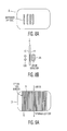
FIGS. 2D1 and 2D2 are side views of cards embodying the invention;
Applicants' invention resides, in part, in the recognition that an existing technology could be modified and adapted to produce cards which could be encoded and/or patterned without the necessity of using up the surface area of the cards.
As light enters the card from either the top or bottom, the light will remain trapped within the semi-reflective material until it can escape from the edges of the card. As the light escapes from the edge of the card the edges of the card will appear to glow. This glowing phenomena can be seen, for example, by illuminating the card with a small flashlight and then visually looking at the edge of the card. To view the light coming out of the edges of the card someone has to actually look at the edge of the card to see if it is present.
The light outputted from the edges of a card formed in accordance with the prior art teaching is diffused and is not of significant use. However, as discussed below, Applicants recognized that the space between the top and bottom surfaces could be coded and/or patterned such that, when illuminated, a significant amount of coded information could be provided.
In FIGS. 2A , 2B and 2C, cards formed in accordance with the invention include light pipe patterns formed within the cards (between its top and bottom surfaces) for producing a predetermined output light pattern at an edge of the cards. That is, when a light pipe pattern is illuminated by a light source, a predetermined output light pattern is produced at the edge (side) of the card. The pattern can then be sensed or read by means of a series of electronic sensors and detectors which can accurately measure the output light pattern being emitted at the edge of the card.
FIG. 2D1 shows a side view looking into the light output side 14 of the card 9. The card 9 may have a total thickness or height (h) of approximately 30 mils. FIG. 2D2 shows a side view looking into the light input side 12 of card 9. The top and bottom surfaces, 11 a and 10 a, respectively, may each have a height of 10 mils and the coded light pattern is formed within a space also having a height of 10 mils. It should be appreciated that these values are by way of example only and that the height of each layer may be made substantially greater or smaller, so long as the total height meets the general standards required of the cards.
In FIGS. 2A , 2B, 2C and 3, the top and bottom surfaces (10, 11) of the cards may formed of an opaque material since the light output pattern is produced at one edge of the card by illuminating another edge of the card.
The light pipes can be made of a material that will only transmit a narrow frequency band (e.g., red, green or yellow). The optical detector will only then validate the card if the signal contains both the correct widths and the predetermined spectra.
Of course the bar/space pattern can be adjusted for each specific customer application. This will allow this technique to have a unique pattern (illumination/opaque) ratio for each application.
In the discussion above, the cards were intended primarily for use in what are known in the art as “insertion readers”, including manual or motorized insertion readers.
In a different embodiment of the invention the light pipe formed in a card does not extend the entire length (or width) of the card. FIGS. 6A and 6B show different views of a card. In FIG. 6A , which is a cross-sectional diagram, the light pipe extends only partially along the width on the length of the card. That is, the light pipe extends from one of the major surfaces of the card to one of the sides of the card. The light pipe is illuminated from one of the top and bottom surfaces and the light is bent at a 90 degree angle and directed towards one edge of the card; where the output light signal is then detected by a detector 30 a. The embodiment of FIG. 6A enables the detection of security features by means of a reader, 101, shown in FIGS. 6C and 6D which uses a manual “swipe” technique (e.g., slot or “swipe” reader). In a manual “swipe” application, the card 9 is typically held in the hand of a user and the lower portion of the card is then inserted and swept through the reader 101.
As shown in FIG. 6C , as the card is passed through a slot reader, the LEDs will illuminate one surface of the card and cause light to be projected via holes or cut-aways 61. When the LEDs align with the input to the light pipe, the detector 30 a will detect the output light pattern produced at the edge of the card. If the light pattern at the edge of the card matches an appropriate configuration, previously stored or programmed in the reader, then the card will be deemed to be valid. In FIG. 6A , when the card surfaces are made opaque, the cut-out 61 to let light in is required. However, note that when the card surface (e.g., surface 10 in FIG. 6A ) is made of a translucent material, there would be no need for holes or cut-aways 61.
Of course, the position of the light and the detector can be interchanged. Thus, in the embodiment shown in FIG. 6A , the one surface 10 of card 9 would be translucent while the other surface 11 could either be opaque or translucent, as shown in FIG. 6E. This is true for all of the embodiments of this invention.
In the discussion above, energizing the light pipe pattern was accomplished by illuminating one end of a light pipe and reading the light output produced at the other end.
However, it is within the ambit of the invention to have an embodiment of the invention in which a pattern is completely embedded within a card, as shown in FIG. 7A. In this example, the picture of a bull is completely embedded within the card. That is, the pattern is placed between the top and bottom surfaces of the card. As shown in FIG. 7B , the card will be placed in a reader housing such that the light is incident on one side of the card and an area detector 30 c is placed on the other side of the card. As the card is inserted into a validation machine (reader), the LEDs illuminate one side of the card which is made of a translucent material. Light will, therefore, pass through the card. However, in the area where the “image of the bull” is located the light will not pass through. The presence or absence of light can then be detected by an area sensor 30C such as a CCD area sensor. If the embedded image matches the preprogrammed security image stored in the reader, the card is deemed valid.
It should be noted that a card may be personalized (customized) by, for example, breaking the fiber strands with a laser. In doing so each card can be personalized to have its own unique pattern, as shown in FIG. 9B.
As shown in FIG. 9B , selected groups of fiber optic strands may be cut (i.e. vaporized) with a laser (or by any other suitable means), as shown by the black stripes 91, 92 and 93 in FIG. 9B. Therefore, the broken strands of optical fibers will not carry light from the light input end of the card to the light output end. In this embodiment, all the fibers could be made identical in terms of their transmissive properties. By cutting selected groups of fiber optic strands a unique pattern can be produced and subsequently detected. However, in FIG. 9B , if the top or bottom surface of the card is translucent, the light input will produce light “marks” at 91, 92 and 93. Therefore, an area reader positioned over a surface of the card for sensing the light emitted at the surface of the card could be used to identify the presence of a light output pattern on the surface of the card.
As shown in FIG. 9C , a reader 91 capable of reading a card of the type shown in FIGS. 9A and 9B includes a light source to illuminate one edge of the card with an optical detector 95 located along a different edge and another optical detector 97 to read one of the surfaces of the card. The detector 97 is then programmed to scan the surface area of the card and to detect where the laser has burned the end of the fiber bundles. As the light leaks out of the end of the fiber bundle that is embedded within the card, it is possible to detect the location where the fibers have been burned. Then the distance between each of the laser cuts (d1 and d2) can be calculated and the information can then be stored on an information storage media on the card (such as a magnetic stripe or an integrated circuit memory).
shown in FIG. 10B by illuminating one surface and sensing the patterned (coded) light out.
The fingerprint parameter can be stored on an information storage media such as a magnetic stripe or an IC memory located on the card. When the card is inserted into the validation reader, the unique fingerprint must match the data stored in the card to validate the card. Otherwise, the card will be rejected as invalid.
As noted above, readers/scanners to illuminate the smart “light cards” embodying the invention and to sense the light pattern output may include an insertion reader (motorized or manual) or a slot reader, as shown in FIGS. 11A and 11B .
It should be evident that the patterning and encoding of cards, as taught herein, may be combined with other prior art security enhancing means for rendering cards embodying the invention even more difficult to counterfeit.
It should be appreciated that the various embodiments of this invention could be incorporated into documents such as passports or visas.
It should also be appreciated that, as shown in FIG. 13 , cards, instruments and documents embodying the invention may include a light pipe or optical fiber sandwiched between two surfaces. Depending on the application, the surfaces may both be opaque, may both be translucent, or one may be opaque and the other translucent.
As shown in FIGS. 14A and 14B , it should be appreciated that cards embodying the invention may be formed by first taking a substrate material 140 which may be opaque or translucent and which will eventually form the top or bottom surface of a card. The substrate material will normally have a thickness in the range of 1 to 15 mils, However, for purpose of illustration it is shown to be 10 mils in these figures. An acrylic material 142 may then be formed on top of the substrate, as shown in FIG. 14B. The material 142 may then be patterned by any known techniques to produce a light pipe as shown in FIG. 14A. A cover (not shown) may then be placed over the pattern previously formed to produce a card embodying the invention. It should be appreciated that this is by way of illustration only and any suitable means for making and encoding the space between the top and bottom surfaces of the card is within the scope of the invention.
When the card is formed with “hidden” pipes, the information pertaining to the pipes and their location may be encoded on a magnetic stripe, a bar code or a semiconductor device located on the card.
The optical fibers 900 a shown in FIGS. 16A and 16B may be used to produce a card of the type shown in FIGS. 17A and 17B . FIG. 17A illustrates that an etched optical fiber 900 a may be placed between the top and bottom surfaces of a card 890 so as to either receive or emit light at a point Lx along the width (or length) of the card. FIG. 17B illustrates that the etched “hidden” fibers may be used to form intricate patterns. In the manufacture of the card 890 (See FIG. 17A), one layer 907 and the adjacent region r1 may be translucent to permit light to pass through and the other layer 909 and the adjacent region r3 may be opaque to block the passage of light. Alternatively, both layers 907, 909 and both regions r1 and r3 may be translucent.
When a card is formed the resulting pattern may be sensed and corresponding data may then be recorded on an information storage medium located on the card. The recording may then be either:
-
- (a) encoded on the card [by means of a magnetic stripe, a bar code, or an integrated circuit (IC) formed on the card or by any other suitable means]; or
- (b) fed into a computer where the information for subsequent comparison with the card is used and read at some later time.
As shown in FIGS. 18A and 18B , a card 890 formed with a plurality of “hidden” light pipes, with the information pertaining to the pipes being encoded on the card, may be inserted in a slot reader 101. The reader includes means for sensing the optical pattern and may also include a sensor to sense the data in the information storage medium pertaining to the pattern. The reader 101 compares the two readings to determine the validity of the card.
There may be more than one layer of light pipes between the top and bottom surfaces of the card. As shown in FIG. 19A , different light pipes may be distributed randomly or arbitrarily at numerous different angles to produce numerous different cards.
- 1—One side of the card can be illuminated (e.g., via light source LS1 in
FIG. 19B ) and (a) the light emanating from any of the other three sides of the card can be sensed by means of photosensors (1,2,3,4,5 inFIGS. 19A and 19B ) located opposite any of the three sides; and/or (b) the light emanating from the top and bottom surfaces of the card can be sensed. - 2—One of the top and bottom surfaces of the card can be illuminated and (a) the light emanating from any of the four sides of the card can be sensed; and/or (b) the light emanating from the other one of the top and bottom surfaces can be sensed.
Sensing of the top and bottom surfaces can be accomplished by means of a linear array or an area array of photo sensors, such as a CCD array. The output pattern produced in response to an illumination signal may be similar to that shown in FIG. 10B—although the resulting pattern may be more complex than theFIG. 10B showing. The output pattern is sensed by a linear or area imaging array and the sensed signals are then processed to produce a digital or analog signal corresponding to the sensed signal(s) and to the underlying pattern. This digital or analog signal, indicative of selected characteristics of the pattern, may then be encoded and may be termed a “security code” which may be stored on the card or in a central computer. The security code may be stored on the card by imparting the corresponding information on a magnetic stripe located on the card, by storing the information in a semiconductor memory chip located on the card, by writing a bar code onto the card at a predetermined location, or by any other similar means for storing data. Subsequently, when the card is about to be used, the card is illuminated and the security code is read and compared with the light pattern output. Then, if there is a match the card is validated.
Instead of storing the security code on the card, the security code may be stored in a central computer which is accessed each time the card is about to be used. That is, when the card is about to be used, the card is illuminated and the light signals are sensed. These signals are then compared with the security code corresponding to the card which is stored in the computer. If the data checks out the card is validated.
It should be appreciated that each card formed in accordance with the invention, as illustrated in FIG. 19A , is formed in a truly random manner. This makes it nearly impossible for forgers to copy and/or falsify these cards.
As shown in FIGS. 18A , 18B, 19A, and 19B, either “pitted” optical fibers 900 a and/or “non-pitted” optical fibers 900 may be used to form random arrangements in accordance with the invention.
As noted above, the inventive concepts described for impeding the counterfeiting of cards, instruments, and documents are also applicable to systems for impeding the counterfeiting of optical data storage discs. Optical data storage discs include compact discs (CD's) which provide, among others, a read-only-memory (ROM) function. The optical data storage disc includes a layer of transparent material formed over one side of the disc with a pattern of indentations defining digital data. This one side of the disc may be covered with a thin coating of reflective material. The digital data is then optically read in any suitable manner (e.g., from the opposite side of the disc).
There is a significant problem associated with the counterfeiting of the information contained on discs, whether the information is in the form of digital data, applications programs, music, etc. A counterfeiter can replicate any existing CD and sell the CD containing the information for 10%, or even less, of the retail price. This sharply cuts into the profits of the legitimate suppliers of the disc.
Applicants' invention is directed to forming security features on a CD and encoding these features on the CD so that these features can be crosschecked to validate the CD. This is best explained with reference to FIG. 20.
In accordance with one aspect of the invention, hair like opaque strands 900 b may be formed within region 204. These optical strands may be optical fibers of different colors for providing different spectral responses (or other suitable light pipes). The strands 900 b may be formed, or placed, within the annular region 204 such that they either: (a) lie horizontally between the top and bottom surfaces of the disc, or along a disc surface, parallel to the surface of the disc; or (b) are mounted vertically between the top and bottom surfaces of the disc.
In accordance with the invention the strands 900 b may be placed and positioned within translucent region 204 in several ways, some of which are as follows:
-
- (a) randomly formed or placed within the
region 204; or - (b) arranged within the
region 204 in an arbitrary and/or programmed manner to produce a unique or predetermined pattern.
- (a) randomly formed or placed within the
In accordance with another aspect of the invention, a plurality of marks, also identified by the reference numeral 900 b, may be etched, scribed or burned (e.g., chemically or via a laser) into region 204. These marks 900 b may be formed in a unique manner or they may be formed arbitrarily, or in accordance with some program. Thus, the CD ROM may be formed with a unique pattern located within the translucent region 204 with either laser etching or by embedding opaque fibers. A large number of different patterns can be generated in this manner. Also, the pattern may be formed at the formation of the CD ROM.
As a finishing step in the manufacture of the CD, the CD may be placed in a CD reader/writer 600 as shown in FIG. 21. The signal or spectral pattern resulting from illuminating the optical strand pattern (see FIG. 20B ) or the optical marks pattern (see FIG. 20C ) in region 204 may be read. FIG. 21 shows a laser/detector 601 which can illuminate the disc and the detect light reflected form the disc. It should be appreciated that when the CD is being read that the reader 600 may be programmed to read only a certain section or sector of the disc (e.g., region 210 in FIG. 20 ) and to record pattern information for that sector. Alternatively, the reader 600 may be programmed to scan the pattern sensed along a radius R1 or a radius R2 as shown in FIG. 20. The signals corresponding to the pattern read are then encoded within a specified area of region 202. Note that this permits the pattern formed on one disc to be made the same as the one formed on another disc. But, by programming the reading of different sections (e.g., by scanning along different radii, R1, R2) of the discs provide a different code to be stored and to be searched for. Interestingly, even if two optical patterns formed on two different discs are the same, by programming scanning of the disc at different radii makes the generation of the security code virtually unique even for apparently like optical patters. Each different radius forms a unique pattern. This pattern may then be used to generate a “unique security code” for the CD ROM. The corresponding information is then encoded and written onto the CD ROM as a hidden file. The information stored in the hidden file is related to the specific radius of the scan and the particular pattern scanned at the programmed radius.
By way of example, as a CD spins within the CD reader/writer, a laser photo detector 601 scans the translucent region 204. The laser scanner 601 and associated signal processing circuitry 603 calculate a “security code” (i.e., the “fingerprint”) associated with the pattern read and determines the “fingerprint” placed on the disc. The “fingerprint” parameter is then written onto the CD, preferably in region 202, as an “hidden” file.
Subsequently when the CD is loaded into an appropriate reading device, the device reads the “hidden” file in region 202. The device can then read (sense) the pattern in region 204 and verify whether the pattern it reads matches the “fingerprint” parameter stored in the hidden file. The pattern formed in region 204 of the disc may be read by the same laser/photodetector circuitry that is used for reading the CD ROM information in region 202. A requirement is that the laser/photodetector be able to scan the region 204 as well as the region 202. If the two regions can not be read with a single laser, then existing equipment would be modified to provide a second laser/photodetector arrangement to scan both regions 202 and 204. When a CD ROM is placed into a reader one of the first steps in validating the CD ROM is to verify whether the security code stored in the hidden file is consistent with the scanned pattern at the programmed scan radius. The validation step may be programmed into the disc or into a reader (e.g. 600) or a combination of both.
Claims (23)
1. A method for impeding a counterfeiting of an instrument having top and bottom surfaces defining a space therebetween comprising the step of:
forming a random optical pattern in one of (a) said top surface, (b) said bottom surface and (c) the space between said top and bottom surfaces, for producing an instrument having an optical pattern which is extremely difficult to duplicate, whereby said random optical pattern and corresponding spectral response are normally different than an optical pattern and a spectral response of any other instrument.
2. A method as claimed in claim 1 wherein the instrument is an optical data storage disc having a region which is translucent and wherein the step of forming random optical patterns includes distributing a multiplicity of strands randomly between the top and bottom surfaces within said translucent region.
3. A method as claimed in claim 2 wherein the strands are opaque fibers.
4. A method as claimed in claim 1 wherein the instrument is an optical data storage disc having a region which is translucent and wherein the step of forming random optical patterns includes etching or laser burning a multiplicity of randomly selected points on one of the top and bottom surfaces within said translucent region.
5. A method as claimed in claim 1 wherein said instrument is an optical data storage disc having a first annular region extending a given distance from the center of the disc and having a second annular region extending between the first annular region and the edge of the disc, wherein said first annular region is translucent and said second annular region is for the storing of data to be read; and wherein the step of forming random patterns includes the step of distributing a multiplicity of strands randomly between the top and bottom surfaces within said first annular region.
6. A method as claimed in claim 5 wherein said strands are opaque fibers.
7. A method as claimed in claim 1 wherein said instrument is an optical data storage disc having a first annular region extending a given distance from the center of the disc and having a second annular region extending between the first annular region and the edge of the disc, wherein said first annular region is translucent and said second annular region is for the storing of data to be read; and wherein the step of forming random patterns includes the step of etching or laser burning a multiplicity of randomly selected points on one of the top and bottom surfaces within said translucent region.
8. A method as claimed in claim 1 further including the steps of:
illuminating the instrument for producing a signal pattern indicative of the random pattern within the instrument; sensing the signal pattern corresponding to the random pattern; and
encoding information corresponding to the signal pattern on an information storage medium located on the instrument.
9. The method as claimed in claim 1 wherein the instrument includes a portion for storing data and wherein the step of forming the optical pattern on or within the instrument occurs simultaneously with the step of writing data into the portion of the instrument intended for the storing of data.
10. A method as claimed in claim 1 wherein said instrument is an optical data storage disc having a first annular region extending a given distance from the center of the disc and having a second annular region extending between the first annular region and the edge of the disc, wherein said first annular region is translucent and said second annular region is for the storing of data to be read; and wherein the step of forming random optical patterns in one of (a) said top surface, (b) said bottom surface and (c) the space between said top and bottom surfaces occurs at the same time as the step of writing data to be stored; the random optical patterns being formed within the first annular region and the data to be stored being written in the second annular region.
11. In an optical data storage disc having a central region with a first translucent annular region surrounding the central region and having a second region surrounding the first region, said second region for storing information to be read by a reading device, the improvement comprising:
a random optical pattern formed within said first region for producing a disc which is extremely difficult to duplicate and having a spectral response within the first translucent region of the disc which is generally different from an optical pattern and a spectral response of any other disc.
12. In an optical data storage disc as claimed in claim 11 , wherein information pertaining to the random optical pattern present in the first translucent region is stored in the second data storage region.
13. In combination with an optical data storage disc as claimed in claim 11 further including:
means for sensing selected characteristics of the random optical pattern formed in the first region and encoding data corresponding thereto within said second region of the disc; and
means for subsequently sensing the pattern formed within the first region and for reading the corresponding encoded data within the second region to validate the disc.
14. In an optical storage disc as claimed in claim 11 wherein the random optical pattern is formed within said first region at the same time as the storing of information into said second region.
15. A combination for impeding a counterfeiting of an optical data storage disc comprising:
an optical data storage disc having a central region with a first translucent annular region surrounding the central region and having a second region surrounding the first region, said second region for storing information to be read by a reading device;
means for forming a random optical pattern within said first region;
means for sensing selected characteristics of the random optical pattern formed in the first region and encoding data corresponding thereto within said second region of the disc; and
means for subsequently sensing the pattern formed within the first region and for reading the corresponding encoded data within the second region to validate the disc.
16. A combination as claimed in claim 15 wherein said means for forming a random optical pattern within said first annular region includes the placement of opaque strands within said first region.
17. A combination as claimed in claim 15 wherein said optical disc has top and bottom surfaces, and wherein the random optical pattern is formed between the top and bottom surfaces.
18. A combination as claimed in claim 15 wherein said means for forming a random optical pattern within said first annular region includes one of etching and laser scribing selected portions of the first annular region of the disc.
19. A combination as claimed in claim 15 wherein the random optical pattern is formed within said first region at the same time as information to be read is stored in the second region.
20. A system for impeding a counterfeiting of an optical data storage disc comprising: an optical data storage disc having a central region with a first translucent annular region surrounding the central region and having a second region surrounding the first region, said second region for storing information to be read by a reading device;
means for forming a random optical pattern within said fist region which is extremely difficult to duplicate;
means for sensing selected characteristics of the random optical pattern formed within the first region and encoding data corresponding thereto within said second region of the disc; and
means for subsequently sensing the pattern formed within the first region and for reading the corresponding encoded data within the second region to determine the validity of the disc.
21. A system as claimed in claim 20 wherein said means for forming an a random optical pattern within said first annular region includes the placement of opaque strands within said first region.
22. A system as claimed in claim 20 wherein said means for forming random optical pattern within said first annular region includes one of etching and laser scribing selected portions of the first region.
23. A system as claimed in claim 20 wherein said information to be read by said reading device is introduced into the disc at the same time as the random optical pattern is formed in said first region.
Priority Applications (2)
| Application Number | Priority Date | Filing Date | Title |
|---|---|---|---|
| US09/745,512 US7104449B2 (en) | 1998-11-12 | 2000-12-22 | Method and apparatus for patterning cards, instruments and documents |
| US10/218,009 US6902111B2 (en) | 1998-11-12 | 2002-08-13 | Method and apparatus for impeding the counterfeiting of discs |
Applications Claiming Priority (2)
| Application Number | Priority Date | Filing Date | Title |
|---|---|---|---|
| US09/190,760 US6193156B1 (en) | 1998-11-12 | 1998-11-12 | Method and apparatus for patterning cards, instruments and documents |
| US09/745,512 US7104449B2 (en) | 1998-11-12 | 2000-12-22 | Method and apparatus for patterning cards, instruments and documents |
Related Parent Applications (1)
| Application Number | Title | Priority Date | Filing Date |
|---|---|---|---|
| US09/190,760 Continuation-In-Part US6193156B1 (en) | 1998-11-12 | 1998-11-12 | Method and apparatus for patterning cards, instruments and documents |
Related Child Applications (1)
| Application Number | Title | Priority Date | Filing Date |
|---|---|---|---|
| US10/218,009 Continuation-In-Part US6902111B2 (en) | 1998-11-12 | 2002-08-13 | Method and apparatus for impeding the counterfeiting of discs |
Publications (2)
| Publication Number | Publication Date |
|---|---|
| US20010010333A1 US20010010333A1 (en) | 2001-08-02 |
| US7104449B2 true US7104449B2 (en) | 2006-09-12 |
Family
ID=26886411
Family Applications (1)
| Application Number | Title | Priority Date | Filing Date |
|---|---|---|---|
| US09/745,512 Expired - Fee Related US7104449B2 (en) | 1998-11-12 | 2000-12-22 | Method and apparatus for patterning cards, instruments and documents |
Country Status (1)
| Country | Link |
|---|---|
| US (1) | US7104449B2 (en) |
Cited By (12)
| Publication number | Priority date | Publication date | Assignee | Title |
|---|---|---|---|---|
| US20080260199A1 (en) * | 2004-08-13 | 2008-10-23 | Ingenia Technology Limited | Authenticity Verification Methods, Products and Apparatuses |
| US20080291788A1 (en) * | 2007-05-22 | 2008-11-27 | Edison Opto Corporation | Optical system for sensing, identification and driving |
| US20110109428A1 (en) * | 2004-03-12 | 2011-05-12 | Ingenia Holdings Limited | System and Method for Article Authentication Using Signatures |
| US20120091195A1 (en) * | 2010-10-14 | 2012-04-19 | Sony Dadc Us Inc. | Loss prevention system with covert marks and method of manufacture thereof |
| US8497983B2 (en) | 2005-12-23 | 2013-07-30 | Ingenia Holdings Limited | Optical authentication |
| US8615475B2 (en) | 2008-12-19 | 2013-12-24 | Ingenia Holdings Limited | Self-calibration |
| US8682076B2 (en) | 2008-12-19 | 2014-03-25 | Ingenia Holdings Limited | Signature generation for use in authentication and verification using a non-coherent radiation source |
| US8699088B2 (en) | 2004-03-12 | 2014-04-15 | Ingenia Holdings Limited | Methods and apparatuses for creating authenticatable printed articles and subsequently verifying them |
| US8892556B2 (en) | 2009-11-10 | 2014-11-18 | Ingenia Holdings Limited | Optimisation |
| US9818249B1 (en) | 2002-09-04 | 2017-11-14 | Copilot Ventures Fund Iii Llc | Authentication method and system |
| US10621482B2 (en) * | 2018-08-31 | 2020-04-14 | National Taiwan Normal University | Graphic two-dimensional barcode and creating method thereof |
| US11250304B1 (en) * | 2020-07-23 | 2022-02-15 | Bank Of America Corporation | Payment card with light-based signature |
Families Citing this family (31)
| Publication number | Priority date | Publication date | Assignee | Title |
|---|---|---|---|---|
| US6973574B2 (en) | 2001-04-24 | 2005-12-06 | Microsoft Corp. | Recognizer of audio-content in digital signals |
| US7020775B2 (en) * | 2001-04-24 | 2006-03-28 | Microsoft Corporation | Derivation and quantization of robust non-local characteristics for blind watermarking |
| DE10318715A1 (en) * | 2003-04-25 | 2004-11-18 | Bundesdruckerei Gmbh Rechts- Und Patentangelegenheiten | Security feature and document with security feature as well as methods for producing and attaching the security feature to a document and method for checking the authenticity of the document |
| US7831832B2 (en) * | 2004-01-06 | 2010-11-09 | Microsoft Corporation | Digital goods representation based upon matrix invariances |
| US20050165690A1 (en) * | 2004-01-23 | 2005-07-28 | Microsoft Corporation | Watermarking via quantization of rational statistics of regions |
| US7497379B2 (en) * | 2004-02-27 | 2009-03-03 | Microsoft Corporation | Counterfeit and tamper resistant labels with randomly occurring features |
| US7770014B2 (en) * | 2004-04-30 | 2010-08-03 | Microsoft Corporation | Randomized signal transforms and their applications |
| ATE410748T1 (en) * | 2004-05-05 | 2008-10-15 | Koninkl Philips Electronics Nv | IDENTIFICATION SYSTEM USING MECHANICAL VIBRATIONS ON THE IDENTIFIER |
| WO2006078220A1 (en) * | 2005-01-19 | 2006-07-27 | Agency For Science, Technology And Research | Identification tag, object adapted to be identified, and related methods, devices and systems |
| US20070076869A1 (en) * | 2005-10-03 | 2007-04-05 | Microsoft Corporation | Digital goods representation based upon matrix invariants using non-negative matrix factorizations |
| JP2007301866A (en) * | 2006-05-12 | 2007-11-22 | Sony Corp | Electronic equipment, printing device, program and consumables |
| US8061619B2 (en) * | 2007-12-19 | 2011-11-22 | Target Brands, Inc. | Transaction card with edge-glow characteristic |
| WO2011032856A1 (en) * | 2009-09-15 | 2011-03-24 | Ksw Microtec Ag | Rfid label |
| EP2426627B1 (en) * | 2010-09-02 | 2016-10-12 | Oberthur Technologies | Luminous module for a microcircuit device |
| FR2964487B1 (en) * | 2010-09-02 | 2013-07-12 | Oberthur Technologies | MICROCIRCUIT CARD COMPRISING A BRIGHT MEANS |
| WO2014058807A1 (en) * | 2012-10-14 | 2014-04-17 | Solarsort Technologies, Inc | Object authentication devices, key-lock mechanism and facilitating equipment |
| DE102014207323B4 (en) | 2014-04-16 | 2018-08-16 | Koenig & Bauer Ag | Method for identifying an object |
| DE102014207318B4 (en) | 2014-04-16 | 2022-03-31 | Koenig & Bauer Ag | Identification feature with several identification elements arranged in a defined, limited area for identifying an object |
| DE102015219394B4 (en) | 2015-10-07 | 2019-01-17 | Koenig & Bauer Ag | Identification feature for identifying an object |
| DE102015219395B4 (en) | 2015-10-07 | 2019-01-17 | Koenig & Bauer Ag | Identification feature with at least two arranged in a defined limited area identification elements for the identification of an object |
| DE102015219393B4 (en) | 2015-10-07 | 2019-01-17 | Koenig & Bauer Ag | Method for identifying an object |
| DE102015219397A1 (en) | 2015-10-07 | 2017-04-13 | Koenig & Bauer Ag | Object with an identification feature arranged for its identification |
| DE102015219396B4 (en) | 2015-10-07 | 2019-01-17 | Koenig & Bauer Ag | Object with an identification feature arranged for its identification |
| DE102015219385A1 (en) | 2015-10-07 | 2017-04-13 | Koenig & Bauer Ag | Method for forming at least one identification feature with a printing press |
| DE102015219388B4 (en) | 2015-10-07 | 2019-01-17 | Koenig & Bauer Ag | Method for the production control of identification features printed with a printing press on a printing material or article |
| DE102015219400B4 (en) | 2015-10-07 | 2019-01-17 | Koenig & Bauer Ag | Method for checking the identity and / or authenticity of an object |
| DE102015219399B4 (en) | 2015-10-07 | 2019-01-17 | Koenig & Bauer Ag | Identification feature for identifying an object |
| DE102015219392B4 (en) | 2015-10-07 | 2019-01-17 | Koenig & Bauer Ag | Identification feature with several arranged in a defined limited area identification elements for the identification of an object |
| DE102016218545A1 (en) | 2015-10-07 | 2017-04-13 | Koenig & Bauer Ag | Identification feature for identifying an object |
| US10628638B1 (en) * | 2019-03-22 | 2020-04-21 | Capital One Services, Llc | Techniques to automatically detect fraud devices |
| US11775532B1 (en) * | 2020-07-15 | 2023-10-03 | Walgreen Co. | Systems and methods for resolving relationships within data sets |
Citations (16)
| Publication number | Priority date | Publication date | Assignee | Title |
|---|---|---|---|---|
| US3648240A (en) * | 1970-01-15 | 1972-03-07 | Identification Corp | Personnel identification apparatus |
| US3728521A (en) * | 1970-09-29 | 1973-04-17 | Bliss & Laughlin Ind | Encoded card employing fiber optic elements |
| US4270153A (en) * | 1979-06-28 | 1981-05-26 | Basf Aktiengesellschaft | Optical control system for transducer positioning apparatus |
| US4671839A (en) * | 1985-12-23 | 1987-06-09 | Xerox Corporation | Secure identification card manufacture |
| US4683371A (en) * | 1981-02-27 | 1987-07-28 | Drexler Technology Corporation | Dual stripe optical data card |
| US4745268A (en) * | 1981-02-27 | 1988-05-17 | Drexler Technology Corporation | Personal information card system |
| US4810868A (en) * | 1985-08-06 | 1989-03-07 | Drexler Technology Corporation | Frasable optical wallet-size data card |
| US5446791A (en) * | 1993-03-17 | 1995-08-29 | Jag Design International Limited | Sound synthesizer system operable by optical data cards |
| US5572589A (en) * | 1993-12-09 | 1996-11-05 | Microsoft Corporation | Disc serialization |
| US5610884A (en) * | 1991-05-09 | 1997-03-11 | Olympus Optical Co., Ltd. | Optical information reproducing apparatus for detecting track crossing direction and track crossing number from reflected light extending over a plurality of tracks |
| US5789733A (en) * | 1996-09-20 | 1998-08-04 | Motorola, Inc. | Smart card with contactless optical interface |
| US5822291A (en) * | 1995-03-23 | 1998-10-13 | Zoom Television, Inc. | Mass storage element and drive unit therefor |
| US5959289A (en) * | 1996-02-13 | 1999-09-28 | Empire Airport Service Co., Ltd. | Card and information recording card and method of using the same |
| US6070799A (en) * | 1997-01-08 | 2000-06-06 | Eastman Kodak Company | Copy protection for a recordable medium and for controlling a recorder |
| US6259575B1 (en) * | 1998-07-01 | 2001-07-10 | Iomega Corporation | Readable indelible mark on storage media |
| US6392832B1 (en) * | 1997-03-26 | 2002-05-21 | Fujitsu Limited | Method for using heat to record on magnetic medium and disk apparatus having temperature changing device |
-
2000
- 2000-12-22 US US09/745,512 patent/US7104449B2/en not_active Expired - Fee Related
Patent Citations (16)
| Publication number | Priority date | Publication date | Assignee | Title |
|---|---|---|---|---|
| US3648240A (en) * | 1970-01-15 | 1972-03-07 | Identification Corp | Personnel identification apparatus |
| US3728521A (en) * | 1970-09-29 | 1973-04-17 | Bliss & Laughlin Ind | Encoded card employing fiber optic elements |
| US4270153A (en) * | 1979-06-28 | 1981-05-26 | Basf Aktiengesellschaft | Optical control system for transducer positioning apparatus |
| US4683371A (en) * | 1981-02-27 | 1987-07-28 | Drexler Technology Corporation | Dual stripe optical data card |
| US4745268A (en) * | 1981-02-27 | 1988-05-17 | Drexler Technology Corporation | Personal information card system |
| US4810868A (en) * | 1985-08-06 | 1989-03-07 | Drexler Technology Corporation | Frasable optical wallet-size data card |
| US4671839A (en) * | 1985-12-23 | 1987-06-09 | Xerox Corporation | Secure identification card manufacture |
| US5610884A (en) * | 1991-05-09 | 1997-03-11 | Olympus Optical Co., Ltd. | Optical information reproducing apparatus for detecting track crossing direction and track crossing number from reflected light extending over a plurality of tracks |
| US5446791A (en) * | 1993-03-17 | 1995-08-29 | Jag Design International Limited | Sound synthesizer system operable by optical data cards |
| US5572589A (en) * | 1993-12-09 | 1996-11-05 | Microsoft Corporation | Disc serialization |
| US5822291A (en) * | 1995-03-23 | 1998-10-13 | Zoom Television, Inc. | Mass storage element and drive unit therefor |
| US5959289A (en) * | 1996-02-13 | 1999-09-28 | Empire Airport Service Co., Ltd. | Card and information recording card and method of using the same |
| US5789733A (en) * | 1996-09-20 | 1998-08-04 | Motorola, Inc. | Smart card with contactless optical interface |
| US6070799A (en) * | 1997-01-08 | 2000-06-06 | Eastman Kodak Company | Copy protection for a recordable medium and for controlling a recorder |
| US6392832B1 (en) * | 1997-03-26 | 2002-05-21 | Fujitsu Limited | Method for using heat to record on magnetic medium and disk apparatus having temperature changing device |
| US6259575B1 (en) * | 1998-07-01 | 2001-07-10 | Iomega Corporation | Readable indelible mark on storage media |
Cited By (21)
| Publication number | Priority date | Publication date | Assignee | Title |
|---|---|---|---|---|
| US9818249B1 (en) | 2002-09-04 | 2017-11-14 | Copilot Ventures Fund Iii Llc | Authentication method and system |
| US8699088B2 (en) | 2004-03-12 | 2014-04-15 | Ingenia Holdings Limited | Methods and apparatuses for creating authenticatable printed articles and subsequently verifying them |
| US8749386B2 (en) * | 2004-03-12 | 2014-06-10 | Ingenia Holdings Limited | System and method for article authentication using signatures |
| US20110109428A1 (en) * | 2004-03-12 | 2011-05-12 | Ingenia Holdings Limited | System and Method for Article Authentication Using Signatures |
| US8896885B2 (en) | 2004-03-12 | 2014-11-25 | Ingenia Holdings Limited | Creating authenticatable printed articles and subsequently verifying them based on scattered light caused by surface structure |
| US8421625B2 (en) | 2004-03-12 | 2013-04-16 | Ingenia Holdings Limited | System and method for article authentication using thumbnail signatures |
| US8766800B2 (en) | 2004-03-12 | 2014-07-01 | Ingenia Holdings Limited | Authenticity verification methods, products, and apparatuses |
| US8502668B2 (en) | 2004-03-12 | 2013-08-06 | Ingenia Holdings Limited | System and method for article authentication using blanket illumination |
| US9019567B2 (en) | 2004-03-12 | 2015-04-28 | Ingenia Holdings Limited | Methods and apparatuses for creating authenticatable printed articles and subsequently verifying them |
| US8757493B2 (en) | 2004-03-12 | 2014-06-24 | Ingenia Holdings Limited | System and method for article authentication using encoded signatures |
| US20080260199A1 (en) * | 2004-08-13 | 2008-10-23 | Ingenia Technology Limited | Authenticity Verification Methods, Products and Apparatuses |
| US8497983B2 (en) | 2005-12-23 | 2013-07-30 | Ingenia Holdings Limited | Optical authentication |
| US20080291788A1 (en) * | 2007-05-22 | 2008-11-27 | Edison Opto Corporation | Optical system for sensing, identification and driving |
| US7628328B2 (en) * | 2007-05-22 | 2009-12-08 | Edison Opto Corporation | Optical system for sensing, identification and driving |
| US8615475B2 (en) | 2008-12-19 | 2013-12-24 | Ingenia Holdings Limited | Self-calibration |
| US8682076B2 (en) | 2008-12-19 | 2014-03-25 | Ingenia Holdings Limited | Signature generation for use in authentication and verification using a non-coherent radiation source |
| US8892556B2 (en) | 2009-11-10 | 2014-11-18 | Ingenia Holdings Limited | Optimisation |
| US20120091195A1 (en) * | 2010-10-14 | 2012-04-19 | Sony Dadc Us Inc. | Loss prevention system with covert marks and method of manufacture thereof |
| US10621482B2 (en) * | 2018-08-31 | 2020-04-14 | National Taiwan Normal University | Graphic two-dimensional barcode and creating method thereof |
| US11615281B2 (en) | 2020-07-23 | 2023-03-28 | Bank Of America Corporation | Payment card with light-based signature |
| US11250304B1 (en) * | 2020-07-23 | 2022-02-15 | Bank Of America Corporation | Payment card with light-based signature |
Also Published As
| Publication number | Publication date |
|---|---|
| US20010010333A1 (en) | 2001-08-02 |
Similar Documents
| Publication | Publication Date | Title |
|---|---|---|
| US7104449B2 (en) | Method and apparatus for patterning cards, instruments and documents | |
| US6193156B1 (en) | Method and apparatus for patterning cards, instruments and documents | |
| US6902111B2 (en) | Method and apparatus for impeding the counterfeiting of discs | |
| US5200794A (en) | Optical head for an optical authenticity identifing system | |
| US7244043B2 (en) | Method and system for a processor controlled illumination system for reading and analyzing materials | |
| US4641017A (en) | Fraud resistant credit card system | |
| EP2002385B1 (en) | Method of reading at least one bar code and system for reading a bar code | |
| US5151582A (en) | Automatic transaction machine system for checking card data and embossed characters | |
| EP2102785B1 (en) | Apparatus and method for secure detection of an item and a method of securing access to information associated with the item | |
| TW469410B (en) | Reading arrangement for information strips with optically encoded information | |
| US7744130B2 (en) | Secure product authentication tags | |
| US4661983A (en) | Secure document identification technique | |
| JPH07210071A (en) | Discrimination system for object | |
| CA2127915C (en) | Magnetic card and card reader apparatus utilizing a pseudo bar code and an address information code | |
| US20100158377A1 (en) | Authentication | |
| CA1313806C (en) | Token having a predetermined optical characteristic, and a token validation device for use therewith | |
| RU2427913C2 (en) | Card that may be authenticated by means of hologram chip | |
| US5456498A (en) | Negotiable instrument fraud detector and processor | |
| US7407101B2 (en) | Card with enhanced security features | |
| US6560017B1 (en) | Compound secure optical identification method and means | |
| US5270526A (en) | Card type recording medium and method of preventing a false use thereof | |
| JPH09245115A (en) | Infrared symbol discriminating reader | |
| JPH0550788A (en) | Card and card reader | |
| EP0412316A2 (en) | Authenticity identifying system for information storage cards | |
| US5231276A (en) | System for preventing a false use of a card type recording medium and a method thereof |
Legal Events
| Date | Code | Title | Description |
|---|---|---|---|
| FPAY | Fee payment |
Year of fee payment: 4 |
|
| SULP | Surcharge for late payment | ||
| REMI | Maintenance fee reminder mailed | ||
| FPAY | Fee payment |
Year of fee payment: 8 |
|
| SULP | Surcharge for late payment |
Year of fee payment: 7 |
|
| FEPP | Fee payment procedure |
Free format text: MAINTENANCE FEE REMINDER MAILED (ORIGINAL EVENT CODE: REM.) |
|
| LAPS | Lapse for failure to pay maintenance fees |
Free format text: PATENT EXPIRED FOR FAILURE TO PAY MAINTENANCE FEES (ORIGINAL EVENT CODE: EXP.); ENTITY STATUS OF PATENT OWNER: SMALL ENTITY |
|
| STCH | Information on status: patent discontinuation |
Free format text: PATENT EXPIRED DUE TO NONPAYMENT OF MAINTENANCE FEES UNDER 37 CFR 1.362 |
|
| FP | Lapsed due to failure to pay maintenance fee |
Effective date: 20180912 |