US7100932B2 - Integrated control and power unit for use aboard a bicycle - Google Patents
Integrated control and power unit for use aboard a bicycle Download PDFInfo
- Publication number
- US7100932B2 US7100932B2 US11/057,819 US5781905A US7100932B2 US 7100932 B2 US7100932 B2 US 7100932B2 US 5781905 A US5781905 A US 5781905A US 7100932 B2 US7100932 B2 US 7100932B2
- Authority
- US
- United States
- Prior art keywords
- unit
- housing
- battery holder
- control unit
- bicycle
- Prior art date
- Legal status (The legal status is an assumption and is not a legal conclusion. Google has not performed a legal analysis and makes no representation as to the accuracy of the status listed.)
- Expired - Fee Related
Links
Images


Classifications
-
- B—PERFORMING OPERATIONS; TRANSPORTING
- B62—LAND VEHICLES FOR TRAVELLING OTHERWISE THAN ON RAILS
- B62K—CYCLES; CYCLE FRAMES; CYCLE STEERING DEVICES; RIDER-OPERATED TERMINAL CONTROLS SPECIALLY ADAPTED FOR CYCLES; CYCLE AXLE SUSPENSIONS; CYCLE SIDE-CARS, FORECARS, OR THE LIKE
- B62K19/00—Cycle frames
- B62K19/30—Frame parts shaped to receive other cycle parts or accessories
- B62K19/34—Bottom brackets
-
- B—PERFORMING OPERATIONS; TRANSPORTING
- B62—LAND VEHICLES FOR TRAVELLING OTHERWISE THAN ON RAILS
- B62J—CYCLE SADDLES OR SEATS; AUXILIARY DEVICES OR ACCESSORIES SPECIALLY ADAPTED TO CYCLES AND NOT OTHERWISE PROVIDED FOR, e.g. ARTICLE CARRIERS OR CYCLE PROTECTORS
- B62J43/00—Arrangements of batteries
- B62J43/20—Arrangements of batteries characterised by the mounting
-
- B—PERFORMING OPERATIONS; TRANSPORTING
- B62—LAND VEHICLES FOR TRAVELLING OTHERWISE THAN ON RAILS
- B62J—CYCLE SADDLES OR SEATS; AUXILIARY DEVICES OR ACCESSORIES SPECIALLY ADAPTED TO CYCLES AND NOT OTHERWISE PROVIDED FOR, e.g. ARTICLE CARRIERS OR CYCLE PROTECTORS
- B62J43/00—Arrangements of batteries
- B62J43/30—Arrangements of batteries for providing power to equipment other than for propulsion
-
- B—PERFORMING OPERATIONS; TRANSPORTING
- B62—LAND VEHICLES FOR TRAVELLING OTHERWISE THAN ON RAILS
- B62J—CYCLE SADDLES OR SEATS; AUXILIARY DEVICES OR ACCESSORIES SPECIALLY ADAPTED TO CYCLES AND NOT OTHERWISE PROVIDED FOR, e.g. ARTICLE CARRIERS OR CYCLE PROTECTORS
- B62J45/00—Electrical equipment arrangements specially adapted for use as accessories on cycles, not otherwise provided for
- B62J45/20—Cycle computers as cycle accessories
-
- B—PERFORMING OPERATIONS; TRANSPORTING
- B62—LAND VEHICLES FOR TRAVELLING OTHERWISE THAN ON RAILS
- B62J—CYCLE SADDLES OR SEATS; AUXILIARY DEVICES OR ACCESSORIES SPECIALLY ADAPTED TO CYCLES AND NOT OTHERWISE PROVIDED FOR, e.g. ARTICLE CARRIERS OR CYCLE PROTECTORS
- B62J9/00—Containers specially adapted for cycles, e.g. panniers or saddle bags
- B62J9/20—Containers specially adapted for cycles, e.g. panniers or saddle bags attached to the cycle as accessories
- B62J9/27—Containers specially adapted for cycles, e.g. panniers or saddle bags attached to the cycle as accessories characterised by mounting arrangements, e.g. quick release arrangements
-
- H—ELECTRICITY
- H01—ELECTRIC ELEMENTS
- H01M—PROCESSES OR MEANS, e.g. BATTERIES, FOR THE DIRECT CONVERSION OF CHEMICAL ENERGY INTO ELECTRICAL ENERGY
- H01M10/00—Secondary cells; Manufacture thereof
- H01M10/42—Methods or arrangements for servicing or maintenance of secondary cells or secondary half-cells
- H01M10/425—Structural combination with electronic components, e.g. electronic circuits integrated to the outside of the casing
- H01M10/4257—Smart batteries, e.g. electronic circuits inside the housing of the cells or batteries
-
- H—ELECTRICITY
- H01—ELECTRIC ELEMENTS
- H01M—PROCESSES OR MEANS, e.g. BATTERIES, FOR THE DIRECT CONVERSION OF CHEMICAL ENERGY INTO ELECTRICAL ENERGY
- H01M50/00—Constructional details or processes of manufacture of the non-active parts of electrochemical cells other than fuel cells, e.g. hybrid cells
- H01M50/20—Mountings; Secondary casings or frames; Racks, modules or packs; Suspension devices; Shock absorbers; Transport or carrying devices; Holders
- H01M50/204—Racks, modules or packs for multiple batteries or multiple cells
- H01M50/207—Racks, modules or packs for multiple batteries or multiple cells characterised by their shape
- H01M50/213—Racks, modules or packs for multiple batteries or multiple cells characterised by their shape adapted for cells having curved cross-section, e.g. round or elliptic
-
- H—ELECTRICITY
- H01—ELECTRIC ELEMENTS
- H01M—PROCESSES OR MEANS, e.g. BATTERIES, FOR THE DIRECT CONVERSION OF CHEMICAL ENERGY INTO ELECTRICAL ENERGY
- H01M50/00—Constructional details or processes of manufacture of the non-active parts of electrochemical cells other than fuel cells, e.g. hybrid cells
- H01M50/20—Mountings; Secondary casings or frames; Racks, modules or packs; Suspension devices; Shock absorbers; Transport or carrying devices; Holders
- H01M50/218—Mountings; Secondary casings or frames; Racks, modules or packs; Suspension devices; Shock absorbers; Transport or carrying devices; Holders characterised by the material
- H01M50/22—Mountings; Secondary casings or frames; Racks, modules or packs; Suspension devices; Shock absorbers; Transport or carrying devices; Holders characterised by the material of the casings or racks
- H01M50/227—Organic material
-
- H—ELECTRICITY
- H01—ELECTRIC ELEMENTS
- H01M—PROCESSES OR MEANS, e.g. BATTERIES, FOR THE DIRECT CONVERSION OF CHEMICAL ENERGY INTO ELECTRICAL ENERGY
- H01M50/00—Constructional details or processes of manufacture of the non-active parts of electrochemical cells other than fuel cells, e.g. hybrid cells
- H01M50/20—Mountings; Secondary casings or frames; Racks, modules or packs; Suspension devices; Shock absorbers; Transport or carrying devices; Holders
- H01M50/249—Mountings; Secondary casings or frames; Racks, modules or packs; Suspension devices; Shock absorbers; Transport or carrying devices; Holders specially adapted for aircraft or vehicles, e.g. cars or trains
-
- H—ELECTRICITY
- H01—ELECTRIC ELEMENTS
- H01M—PROCESSES OR MEANS, e.g. BATTERIES, FOR THE DIRECT CONVERSION OF CHEMICAL ENERGY INTO ELECTRICAL ENERGY
- H01M50/00—Constructional details or processes of manufacture of the non-active parts of electrochemical cells other than fuel cells, e.g. hybrid cells
- H01M50/20—Mountings; Secondary casings or frames; Racks, modules or packs; Suspension devices; Shock absorbers; Transport or carrying devices; Holders
- H01M50/271—Lids or covers for the racks or secondary casings
-
- B—PERFORMING OPERATIONS; TRANSPORTING
- B62—LAND VEHICLES FOR TRAVELLING OTHERWISE THAN ON RAILS
- B62J—CYCLE SADDLES OR SEATS; AUXILIARY DEVICES OR ACCESSORIES SPECIALLY ADAPTED TO CYCLES AND NOT OTHERWISE PROVIDED FOR, e.g. ARTICLE CARRIERS OR CYCLE PROTECTORS
- B62J45/00—Electrical equipment arrangements specially adapted for use as accessories on cycles, not otherwise provided for
-
- H—ELECTRICITY
- H01—ELECTRIC ELEMENTS
- H01M—PROCESSES OR MEANS, e.g. BATTERIES, FOR THE DIRECT CONVERSION OF CHEMICAL ENERGY INTO ELECTRICAL ENERGY
- H01M10/00—Secondary cells; Manufacture thereof
- H01M10/42—Methods or arrangements for servicing or maintenance of secondary cells or secondary half-cells
- H01M10/46—Accumulators structurally combined with charging apparatus
-
- H—ELECTRICITY
- H01—ELECTRIC ELEMENTS
- H01M—PROCESSES OR MEANS, e.g. BATTERIES, FOR THE DIRECT CONVERSION OF CHEMICAL ENERGY INTO ELECTRICAL ENERGY
- H01M50/00—Constructional details or processes of manufacture of the non-active parts of electrochemical cells other than fuel cells, e.g. hybrid cells
- H01M50/50—Current conducting connections for cells or batteries
-
- Y—GENERAL TAGGING OF NEW TECHNOLOGICAL DEVELOPMENTS; GENERAL TAGGING OF CROSS-SECTIONAL TECHNOLOGIES SPANNING OVER SEVERAL SECTIONS OF THE IPC; TECHNICAL SUBJECTS COVERED BY FORMER USPC CROSS-REFERENCE ART COLLECTIONS [XRACs] AND DIGESTS
- Y02—TECHNOLOGIES OR APPLICATIONS FOR MITIGATION OR ADAPTATION AGAINST CLIMATE CHANGE
- Y02E—REDUCTION OF GREENHOUSE GAS [GHG] EMISSIONS, RELATED TO ENERGY GENERATION, TRANSMISSION OR DISTRIBUTION
- Y02E60/00—Enabling technologies; Technologies with a potential or indirect contribution to GHG emissions mitigation
- Y02E60/10—Energy storage using batteries
-
- Y—GENERAL TAGGING OF NEW TECHNOLOGICAL DEVELOPMENTS; GENERAL TAGGING OF CROSS-SECTIONAL TECHNOLOGIES SPANNING OVER SEVERAL SECTIONS OF THE IPC; TECHNICAL SUBJECTS COVERED BY FORMER USPC CROSS-REFERENCE ART COLLECTIONS [XRACs] AND DIGESTS
- Y10—TECHNICAL SUBJECTS COVERED BY FORMER USPC
- Y10S—TECHNICAL SUBJECTS COVERED BY FORMER USPC CROSS-REFERENCE ART COLLECTIONS [XRACs] AND DIGESTS
- Y10S224/00—Package and article carriers
- Y10S224/902—Battery carrier
-
- Y—GENERAL TAGGING OF NEW TECHNOLOGICAL DEVELOPMENTS; GENERAL TAGGING OF CROSS-SECTIONAL TECHNOLOGIES SPANNING OVER SEVERAL SECTIONS OF THE IPC; TECHNICAL SUBJECTS COVERED BY FORMER USPC CROSS-REFERENCE ART COLLECTIONS [XRACs] AND DIGESTS
- Y10—TECHNICAL SUBJECTS COVERED BY FORMER USPC
- Y10S—TECHNICAL SUBJECTS COVERED BY FORMER USPC CROSS-REFERENCE ART COLLECTIONS [XRACs] AND DIGESTS
- Y10S224/00—Package and article carriers
- Y10S224/929—Article carrier for electrical device
Definitions
- This invention relates to an integrated control and power unit for use aboard a bicycle, comprising a housing for an electronic control unit and a holder container for one or more batteries for powering electrical devices fitted aboard the bicycle.
- the object of this invention is to improve the previously proposed unit, making it increasingly simpler and more functional.
- this invention relates to a unit, having the above specified features, and additionally characterised in that the housing of the control unit and the battery holder container are provided with quick coupling means, that, when coupled, also provide the electrical connection between the batteries and the control unit.
- battery holder container can be assembled and electrically connected in an extremely simple and rapid manner. This advantage is very important, especially when needing to fully replace the battery holder container during a cycling competition. In general, however, as specified below, the container will not be replaced, but simply temporarily removed for recharging.
- the quick coupling means comprise a circular seat, formed in the body of the housing of the control unit, and a cylindrical end portion of the battery holder, which can be received within this seat.
- other coupling means can be made in an equivalent fashion by reversing the male and female functions on the battery holder container and on the housing of the control unit.
- the external surface of the cylindrical end portion of the battery holder has one or more electrical contacts leading to the batteries and suitable for engaging corresponding electrical contacts in the seat, once the coupled condition is obtained.
- each of the electrical contacts on the external surface of the cylindrical end portion of the battery holder container consists of a ring of conductive material surrounding the cylindrical portion.
- each of the contacts arranged in the seat for the battery holder container includes a pin, which is elastically biased towards a position radially projecting within this seat.
- the ring forming each electrical contact on the battery holder container has an external surface defining a round recess for receiving and axially locking the respective contact pin in the seat receiving the battery holder container.
- the contact pins also perform a mechanical retaining function.
- the battery or the batteries, are rechargeable.
- the container in which they are housed is hermetically closed and the batteries can be recharged by placing this container in a specifically dedicated seat in a battery charger, which is totally similar to the seat in the housing of the electronic control unit. In this way, the batteries do not need to be removed from the container for recharging.
- the battery holder container comprises a entirely cylindrical elongated body closed on one end and equipped with a closing cap on the opposite end.
- a coil spring is arranged between the batteries and the closed end of the container to dampen all vibrations (and the consequent noise) of the batteries inside the container.
- Any number of electrical contacts can be provided, because accessory terminals can be arranged, in addition to the two power terminals.
- FIG. 1 is a perspective view of the unit according to this invention illustrated in a mounted condition.
- FIG. 2 is a perspective view of the unit shown in FIG. 1 illustrated in a disconnected condition.
- FIG. 3 is a perspective exploded view of the unit according to this invention.
- FIG. 4 is a parallel perspective view of the frame of the bicycle having a unit according to the invention mounted thereon.
- FIG. 5 is a perspective view of a bicycle frame with a second embodiment of the unit according to the invention.
- FIG. 6 is an exploded perspective view, at an enlarged scale, of a detail of FIG. 5 .
- FIG. 7 is a cross-section view of the device according to the invention as shown in FIGS. 5 , 6 , in its mounted condition.
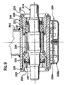
- FIGS. 8 , 9 show variants of FIGS. 6 , 7 with reference to further version of device according to the invention.
- numeral 1 generally indicates an integrated control and power unit usable aboard a bicycle, comprising a housing 2 containing one or more electronic circuit boards forming the electronic control unit, i.e. the bicycle on-board computer, as well as a cylindrical container 3 holding one or more batteries for powering the various electrical devices aboard the bicycle.
- the battery holder container 3 comprises a lower end portion 10 , which is received in an annular cylindrical seat 6 , forming an integral part of the body of the housing 2 .
- the annular seat 6 projects from a riser 7 extending vertically upwards from one end of the box 2 , which is substantially flat and rectangular.
- the riser 7 of the housing 2 presents a hole 8 for engaging a screw for fastening the housing to the bicycle frame at the fastening holes formed in a tube of the bicycle frame, and used for mounting the bottle-cage.
- the battery holder container 3 presents an elongated tubular cylindrical conformation, which is closed on one end by a partition 3 a and on the opposite end by a cap 3 b , which is clipped on and welded to the body of the container 3 , such elements being both made of plastic insulating material.
- the container 3 has two round grooves 3 c on the upper end, which receives two circular cross-section rubber rings 9 , suitable for grasping easily the upper end of the container 3 .
- the container 3 presents a cylindrical portion 10 , which is to be received inside the seat 6 .
- a circular cross-section rubber ring 11 , a metallic conductive material ring 12 , a plastic material shim ring 13 , an additional metallic conductive material ring 14 , an additional rubber ring 15 and finally a cap 3 b are arranged in sequence on the cylindrical portion 10 .
- the two metallic rings 12 , 14 are reciprocally isolated and form two electrical contacts which are respectively connected to the two terminals of the battery, or of the batteries, arranged inside the container 3 . This connection is attained by means of the respective conductor wires, or metallic reeds, which are arranged inside the container 3 , and which project from the container through a slot 26 , arranged in the cylindrical portion 10 so as to be connected to the two rings 12 , 14 .
- any number of electrical contacts can be arranged.
- the two rubber rings 11 , 15 ensure tightness, preventing infiltration of water in the area of the electrical contacts 12 , 14 .
- the cap 3 b is permanently welded to the container 3 after inserting the batteries. The latter can be made according to any known technique and are rechargeable.
- an axial recess 6 a is provided on the inner surface of the annular seat 6 in which a guiding box 16 for two ball headed metallic pins 17 , 18 which are biased by coil springs 19 towards a radially projecting position inside the annular seat 6 .
- the pins 17 , 18 form two electrical contacts suitable for establishing contact with the two rings 12 , 14 of the battery holder container when the latter is inserted in the seat 6 .
- the springs 19 are arranged between a movable plate 20 with two pins 17 , 18 and a counter plate 21 which is secured to an end of the housing 2 .
- the two rings 12 , 14 establish contact with the two contact pins 17 , 18 (also see FIG. 2 ).
- the external surface of the ring 12 and the ring 14 is formed to present a circumferential groove with a rounded cross-section, to provide an axial retention with respect to the contact pins 17 or 18 .
- the two pins 17 , 18 ensure both the mechanical connection and the electrical connection.
- the surface thus formed of each ring 12 , 14 also produces a cam effect that determines the retraction of the pins 17 , 18 when the battery holder container 3 is extracted.
- the battery, or the batteries, arranged in the container 3 rest against the end 3 a of the container with a coil spring 22 arranged in-between, preventing movements inside the container.
- FIG. 3 illustrates an additional supporting element of the container 3 on the bicycle frame, comprising a plate 23 with a hole 24 for engagement of a fastening screw to be screwed into a hole of a tube of the bicycle frame and a semicircular grip 25 for engaging the container 3 laterally.
- the screws engaging the holes 24 and 8 can engage, for example, the two holes usually provided in a tube of the bicycle frame for attaching the bottle-cage of the bicycle (see FIG. 4 ).
- the same screws are used to attach both the bottle-cage and the unit of the invention.
- FIG. 4 depicts the control and power unit according to the preferred embodiment of the present invention mounted on a down tube 55 of a bicycle frame.
- numeral 101 generally designates a bicycle frame, including a front steering tube 102 which is connected to a rear saddle tube 103 through a horizontal tube 104 and a diagonal tube 105 .
- Tubes 103 , 105 converge into a housing 106 for the bicycle crank axle, having a substantially cylindrical shape with a horizontal axis (with reference to the condition of use of the bicycle).
- Reference numeral 107 generally designates an electronic control unit according to the invention, including a rigid housing 108 for housing one or more electronic circuit boards for controlling one or more electronic components mounted on board the bicycle.
- the housing 108 has a substantially flattened shape, with a lower surface 109 which is substantially planar and an upper surface 110 including a cradle-like portion 111 of curved shape which is for engaging the lower surface of the housing 106 while keeping the dimension of the housing 108 along the vertical direction at the minimum.
- the housing 108 further comprises a tubular body 112 acting as a seat for a quick mechanical and electrical coupling with the lower end of a cylindrical holder container 113 containing the batteries.
- the holder 113 is sealed and has two outer metal rings 114 at its lower end, which are insulated from each other, acting as contacts and adapted to co-operate with the two contact pins (not shown in FIG. 6 ) provided within the seat 112 and biased radially inwardly by spring means, in a manner similar to what has been disclosed with reference to the first embodiment of the invention.
- the housing 108 is constituted by a body including an upper half-shell 108 a and a lower half-shell 108 b both made of plastic material and connected to each other (e.g. by welling). These half-shells together define a through hole 115 having a cylindrical surface 117 , for engagement of a screw 118 serving for fastening the housing 108 to the housing 106 of the crank axle.
- the screw 118 is engaged within a threaded hole 118 a of the housing of the crank axle which is conventionally provided, unconventional bicycles, for fastening a guiding plate which guides the cables controlling the front and rear derailleurs, where the bicycle is provided with a derailleur manual control device.
- FIG. 7 shows the housing 106 in cross-section.
- a crank axle 119 which is rotatably abutment through rolling bearings 110 , 121 , 122 by two threaded bush 123 , 124 which are screwed within the housing 106 .
- the bush 123 has an enlarged head 125 which comes into abutment against one end surface of the housing 106 , whereas the bush 124 is received completely inside the housing 106 and presses a tubular spacer 126 against the assembly of bearings 121 , 122 which is supported by the other bush 123 .
- sealing rings 127 , 128 are further associated to bearings 120 , 121 and 122 .
- FIGS. 8 , 9 refer to a further version of the device according to the invention, in which fastening of the housing 208 to housing 206 is obtained in a different manner.
- the housing 208 incorporates two annular ears 229 which are parallel and spaced apart from each other and project upwardly from the upper surface 210 of the housing 208 and are arranged in planes perpendicular to the axis of the crank axle, with reference to the mounted condition on the bicycle.
- the two ears 229 are secured against the respective ends of the housing 206 of the crank axle by means of the two above-mentioned threaded bushes 223 , 224 ( FIG. 9 ).
- both threaded bushes 223 , 224 have an enlarged head 225 and the two ears 229 are each mounted around the respective bush 223 and 224 , between the respective enlarged head 225 and the respective end surface of the housing 206 .
- control unit is adapted to be secured to bicycle frame at a position which is not of hindrance to the normal use of a bicycle while enabling an easy access for carrying out maintenance or replacement operations, or for removing and mounting the battery holder before each recharging operation.
Abstract
A housing for an electronic control unit for use with a bicycle and a battery container for powering electrical devices thereon has a quick couple that when coupled, provides the electrical connection between the batteries and the control unit.
Description
This application is a continuation of U.S. patent application Ser. No. 10/736,325 filed on Dec. 15, 2003, now U.S. Pat. No. 6,896,277 issued on May 24, 2005, which is a continuation of Ser. No. 09/951,549 filed Sep. 14, 2001, now U.S. Pat. No. 6,669,220, which issued on Dec. 30, 2003. Both of these patents are incorporated by reference herein as if fully set forth.
This invention relates to an integrated control and power unit for use aboard a bicycle, comprising a housing for an electronic control unit and a holder container for one or more batteries for powering electrical devices fitted aboard the bicycle. The object of this invention is to improve the previously proposed unit, making it increasingly simpler and more functional.
In order to attain this object, this invention relates to a unit, having the above specified features, and additionally characterised in that the housing of the control unit and the battery holder container are provided with quick coupling means, that, when coupled, also provide the electrical connection between the batteries and the control unit.
Due to these features, battery holder container can be assembled and electrically connected in an extremely simple and rapid manner. This advantage is very important, especially when needing to fully replace the battery holder container during a cycling competition. In general, however, as specified below, the container will not be replaced, but simply temporarily removed for recharging.
In a preferred embodiment, the quick coupling means comprise a circular seat, formed in the body of the housing of the control unit, and a cylindrical end portion of the battery holder, which can be received within this seat. Obviously, however, other coupling means can be made in an equivalent fashion by reversing the male and female functions on the battery holder container and on the housing of the control unit.
Always in the case of the preferred embodiment, the external surface of the cylindrical end portion of the battery holder has one or more electrical contacts leading to the batteries and suitable for engaging corresponding electrical contacts in the seat, once the coupled condition is obtained.
According to an additional preferred characteristic, each of the electrical contacts on the external surface of the cylindrical end portion of the battery holder container consists of a ring of conductive material surrounding the cylindrical portion. At the same time, each of the contacts arranged in the seat for the battery holder container includes a pin, which is elastically biased towards a position radially projecting within this seat.
Due to these characteristics, both the mechanical and electrical coupling is obtained for any angular position of the cylindrical portion of the battery holder container within its seat.
According to an additional preferred characteristic, the ring forming each electrical contact on the battery holder container has an external surface defining a round recess for receiving and axially locking the respective contact pin in the seat receiving the battery holder container. In this way, the contact pins also perform a mechanical retaining function.
Preferably, the battery, or the batteries, are rechargeable. The container in which they are housed is hermetically closed and the batteries can be recharged by placing this container in a specifically dedicated seat in a battery charger, which is totally similar to the seat in the housing of the electronic control unit. In this way, the batteries do not need to be removed from the container for recharging.
According to yet another characteristic, the battery holder container comprises a entirely cylindrical elongated body closed on one end and equipped with a closing cap on the opposite end. A coil spring is arranged between the batteries and the closed end of the container to dampen all vibrations (and the consequent noise) of the batteries inside the container.
Any number of electrical contacts can be provided, because accessory terminals can be arranged, in addition to the two power terminals.
This invention will be better explained by the following detailed description with reference to the accompanying figures as non-limiting example.
With reference to FIGS. 1 , 2, numeral 1 generally indicates an integrated control and power unit usable aboard a bicycle, comprising a housing 2 containing one or more electronic circuit boards forming the electronic control unit, i.e. the bicycle on-board computer, as well as a cylindrical container 3 holding one or more batteries for powering the various electrical devices aboard the bicycle. The battery holder container 3 comprises a lower end portion 10, which is received in an annular cylindrical seat 6, forming an integral part of the body of the housing 2. In the example shown, the annular seat 6 projects from a riser 7 extending vertically upwards from one end of the box 2, which is substantially flat and rectangular. Naturally, the specific conformation of the housing 2 and the container 3 illustrated in the drawings as non-limiting examples can be widely varied. The riser 7 of the housing 2 presents a hole 8 for engaging a screw for fastening the housing to the bicycle frame at the fastening holes formed in a tube of the bicycle frame, and used for mounting the bottle-cage.
With reference to FIG. 3 , the battery holder container 3 presents an elongated tubular cylindrical conformation, which is closed on one end by a partition 3 a and on the opposite end by a cap 3 b, which is clipped on and welded to the body of the container 3, such elements being both made of plastic insulating material. The container 3 has two round grooves 3 c on the upper end, which receives two circular cross-section rubber rings 9, suitable for grasping easily the upper end of the container 3. On the lower end, the container 3 presents a cylindrical portion 10, which is to be received inside the seat 6. A circular cross-section rubber ring 11, a metallic conductive material ring 12, a plastic material shim ring 13, an additional metallic conductive material ring 14, an additional rubber ring 15 and finally a cap 3 b are arranged in sequence on the cylindrical portion 10. The two metallic rings 12, 14 are reciprocally isolated and form two electrical contacts which are respectively connected to the two terminals of the battery, or of the batteries, arranged inside the container 3. This connection is attained by means of the respective conductor wires, or metallic reeds, which are arranged inside the container 3, and which project from the container through a slot 26, arranged in the cylindrical portion 10 so as to be connected to the two rings 12, 14. As mentioned, however, any number of electrical contacts can be arranged. The two rubber rings 11, 15 ensure tightness, preventing infiltration of water in the area of the electrical contacts 12, 14. As mentioned, the cap 3 b is permanently welded to the container 3 after inserting the batteries. The latter can be made according to any known technique and are rechargeable.
As appears in FIG. 3 , an axial recess 6 a is provided on the inner surface of the annular seat 6 in which a guiding box 16 for two ball headed metallic pins 17, 18 which are biased by coil springs 19 towards a radially projecting position inside the annular seat 6. The pins 17, 18 form two electrical contacts suitable for establishing contact with the two rings 12, 14 of the battery holder container when the latter is inserted in the seat 6. The springs 19 are arranged between a movable plate 20 with two pins 17, 18 and a counter plate 21 which is secured to an end of the housing 2.
When the battery holder container 3 is received in the seat 6, the two rings 12, 14 establish contact with the two contact pins 17, 18 (also see FIG. 2 ). Preferably, the external surface of the ring 12 and the ring 14 is formed to present a circumferential groove with a rounded cross-section, to provide an axial retention with respect to the contact pins 17 or 18. In this way, the two pins 17, 18 ensure both the mechanical connection and the electrical connection. The surface thus formed of each ring 12, 14 also produces a cam effect that determines the retraction of the pins 17, 18 when the battery holder container 3 is extracted.
As mentioned, the battery, or the batteries, arranged in the container 3 rest against the end 3 a of the container with a coil spring 22 arranged in-between, preventing movements inside the container.
In FIG. 5 , numeral 101 generally designates a bicycle frame, including a front steering tube 102 which is connected to a rear saddle tube 103 through a horizontal tube 104 and a diagonal tube 105. Tubes 103, 105 converge into a housing 106 for the bicycle crank axle, having a substantially cylindrical shape with a horizontal axis (with reference to the condition of use of the bicycle).
With reference to FIG. 6 , the housing 108 has a substantially flattened shape, with a lower surface 109 which is substantially planar and an upper surface 110 including a cradle-like portion 111 of curved shape which is for engaging the lower surface of the housing 106 while keeping the dimension of the housing 108 along the vertical direction at the minimum. The housing 108 further comprises a tubular body 112 acting as a seat for a quick mechanical and electrical coupling with the lower end of a cylindrical holder container 113 containing the batteries. The holder 113 is sealed and has two outer metal rings 114 at its lower end, which are insulated from each other, acting as contacts and adapted to co-operate with the two contact pins (not shown in FIG. 6 ) provided within the seat 112 and biased radially inwardly by spring means, in a manner similar to what has been disclosed with reference to the first embodiment of the invention.
With reference to FIGS. 6 , 7 the housing 108 is constituted by a body including an upper half-shell 108 a and a lower half-shell 108 b both made of plastic material and connected to each other (e.g. by welling). These half-shells together define a through hole 115 having a cylindrical surface 117, for engagement of a screw 118 serving for fastening the housing 108 to the housing 106 of the crank axle. The screw 118 is engaged within a threaded hole 118 a of the housing of the crank axle which is conventionally provided, unconventional bicycles, for fastening a guiding plate which guides the cables controlling the front and rear derailleurs, where the bicycle is provided with a derailleur manual control device. FIG. 7 shows the housing 106 in cross-section. Inside housing 106 there is arranged a crank axle 119 which is rotatably abutment through rolling bearings 110, 121, 122 by two threaded bush 123, 124 which are screwed within the housing 106. The bush 123 has an enlarged head 125 which comes into abutment against one end surface of the housing 106, whereas the bush 124 is received completely inside the housing 106 and presses a tubular spacer 126 against the assembly of bearings 121, 122 which is supported by the other bush 123. According to a technique known per se, sealing rings 127, 128 are further associated to bearings 120, 121 and 122.
As clearly apparent from the foregoing description, the control unit according to the invention is adapted to be secured to bicycle frame at a position which is not of hindrance to the normal use of a bicycle while enabling an easy access for carrying out maintenance or replacement operations, or for removing and mounting the battery holder before each recharging operation.
Naturally, numerous changes can be implemented to the construction and embodiment of the invention described herein without departing from the scope of the present invention, as defined by the following claims.
Claims (11)
1. An integrated control and power unit for use aboard a bicycle, comprising:
a housing that receives an electronic control unit for controlling an electrical device on a bicycle, having an externally accessible electrical connector that is operatively connected to the control unit; and
a battery holder for providing electrical power, having an electrical connector that mates with the externally accessible electrical connector;
wherein the housing of the control unit and the battery holder are quickly coupled in a substantially circular quick couple that provides an electrical connection between the battery holder and the control unit.
2. The unit of claim 1 wherein the battery holder and the control unit are quickly coupled using a circular seat formed in the housing of the control unit and a cylindrical end portion of the battery holder, which can be received within the seat.
3. The unit of claim 2 wherein the cylindrical end portion of the battery holder container has one or more electrical contacts on the external surface leading to the batteries and suitable for engaging corresponding contacts in the seat, once the coupled condition is obtained.
4. The unit of claim 3 wherein the electrical contacts on the external surface of the cylindrical end portion of the battery holder container comprise a ring of conductive material surrounding the cylindrical portion.
5. The unit of claim 1 wherein the battery holder has an axis of rotation and the electrical connection between the battery holder and the control unit, when coupled, is maintained when the battery holder container rotates about the axis.
6. An integrated control and power unit for use aboard a bicycle, the unit comprising:
a housing that receives an electronic controller for controlling an electrical device on a bicycle, and has an externally accessible electrical connector around a perimeter thereof, having a first configuration that is operatively connected to the control unit; and
an electrical power pack having an electrical connector of a second configuration that mates with the first configuration of the externally accessible electrical connector;
wherein the first and second configurations are quickly coupled to provide an electrical connection between the power pack and the controller.
7. The unit of claim 6 wherein the quick coupling between the power pack and the housing comprises a circular seat formed in the housing and a cylindrical end portion of the power pack that can be received within this seat.
8. The unit of claim 7 wherein the cylindrical end portion of the power pack has one or more electrical contacts on an external surface leading to batteries that are suitable for engaging corresponding contacts in the seat once the coupled condition is obtained.
9. The unit of claim 8 wherein the electrical contacts comprise a ring of conductive material surrounding the cylindrical end portion.
10. The unit of claim 6 wherein the power pack has an axis of rotation and the electrical connection between the power pack and the controller, when coupled, is maintained despite the orientation of when the power pack rotates about the axis.
11. An integrated control and power unit for use aboard a bicycle comprising a housing for an electronic control unit and a holder container for one or more batteries for powering electrical devices fitted aboard the bicycle,
wherein the housing of the control unit and the battery holder container are provided with quick coupling means that, when coupled, also provide the electrical connection between the batteries and the control unit;
wherein the housing is configured for mounting on the down tube of the bicycle.
Priority Applications (2)
| Application Number | Priority Date | Filing Date | Title |
|---|---|---|---|
| US11/057,819 US7100932B2 (en) | 2000-09-15 | 2005-02-14 | Integrated control and power unit for use aboard a bicycle |
| US11/516,001 US20070003828A1 (en) | 2000-09-15 | 2006-09-05 | Integrated control and power unit use aboard a bicycle |
Applications Claiming Priority (7)
| Application Number | Priority Date | Filing Date | Title |
|---|---|---|---|
| ITT02000A00869 | 2000-09-15 | ||
| IT2000TO000869A IT1320645B1 (en) | 2000-09-15 | 2000-09-15 | Integrated controls and electric supply module for use on bicycles, uses cylindrical housing for batteries that screws into socket in control module |
| IT2000TO001028A IT1320740B1 (en) | 2000-10-31 | 2000-10-31 | Integrated controls and electric supply module for use on bicycles, uses cylindrical housing for batteries that screws into socket in control module |
| US09/951,549 US6669220B2 (en) | 2000-09-15 | 2001-09-14 | Integrated control and power unit for use aboard a bicycle |
| ITT02000A001028 | 2003-10-31 | ||
| US10/736,325 US6896277B2 (en) | 2000-09-15 | 2003-12-15 | Integrated control and power unit for use aboard a bicycle |
| US11/057,819 US7100932B2 (en) | 2000-09-15 | 2005-02-14 | Integrated control and power unit for use aboard a bicycle |
Related Parent Applications (1)
| Application Number | Title | Priority Date | Filing Date |
|---|---|---|---|
| US10/736,325 Continuation US6896277B2 (en) | 2000-09-15 | 2003-12-15 | Integrated control and power unit for use aboard a bicycle |
Related Child Applications (1)
| Application Number | Title | Priority Date | Filing Date |
|---|---|---|---|
| US11/516,001 Continuation US20070003828A1 (en) | 2000-09-15 | 2006-09-05 | Integrated control and power unit use aboard a bicycle |
Publications (2)
| Publication Number | Publication Date |
|---|---|
| US20050142437A1 US20050142437A1 (en) | 2005-06-30 |
| US7100932B2 true US7100932B2 (en) | 2006-09-05 |
Family
ID=26332871
Family Applications (4)
| Application Number | Title | Priority Date | Filing Date |
|---|---|---|---|
| US09/951,549 Expired - Fee Related US6669220B2 (en) | 2000-09-15 | 2001-09-14 | Integrated control and power unit for use aboard a bicycle |
| US10/736,325 Expired - Fee Related US6896277B2 (en) | 2000-09-15 | 2003-12-15 | Integrated control and power unit for use aboard a bicycle |
| US11/057,819 Expired - Fee Related US7100932B2 (en) | 2000-09-15 | 2005-02-14 | Integrated control and power unit for use aboard a bicycle |
| US11/516,001 Abandoned US20070003828A1 (en) | 2000-09-15 | 2006-09-05 | Integrated control and power unit use aboard a bicycle |
Family Applications Before (2)
| Application Number | Title | Priority Date | Filing Date |
|---|---|---|---|
| US09/951,549 Expired - Fee Related US6669220B2 (en) | 2000-09-15 | 2001-09-14 | Integrated control and power unit for use aboard a bicycle |
| US10/736,325 Expired - Fee Related US6896277B2 (en) | 2000-09-15 | 2003-12-15 | Integrated control and power unit for use aboard a bicycle |
Family Applications After (1)
| Application Number | Title | Priority Date | Filing Date |
|---|---|---|---|
| US11/516,001 Abandoned US20070003828A1 (en) | 2000-09-15 | 2006-09-05 | Integrated control and power unit use aboard a bicycle |
Country Status (6)
| Country | Link |
|---|---|
| US (4) | US6669220B2 (en) |
| JP (1) | JP2002145152A (en) |
| CZ (1) | CZ300405B6 (en) |
| DE (1) | DE10145503A1 (en) |
| FR (1) | FR2814139A1 (en) |
| TW (1) | TW558537B (en) |
Cited By (11)
| Publication number | Priority date | Publication date | Assignee | Title |
|---|---|---|---|---|
| US20080088108A1 (en) * | 2006-10-11 | 2008-04-17 | Shimano Inc. | Bicycle battery holder assembly |
| US20090207624A1 (en) * | 2008-02-15 | 2009-08-20 | Acumen, Inc. | Headlight assembly permitting compensation for visibility changes |
| US20090261134A1 (en) * | 2008-04-21 | 2009-10-22 | Shimano Inc. | Bicycle battery holder |
| US20130241170A1 (en) * | 2012-03-16 | 2013-09-19 | Specialized Bicycle Components, Inc. | Bicycle with battery mount |
| US9163707B2 (en) | 2011-09-30 | 2015-10-20 | Mtd Products Inc | Method for controlling the speed of a self-propelled walk-behind lawn mower |
| US9394030B2 (en) | 2012-09-27 | 2016-07-19 | Sram, Llc | Rear derailleur |
| US9399499B2 (en) | 2011-06-29 | 2016-07-26 | Shimano Inc. | Bicycle battery holder |
| US9502702B2 (en) | 2015-02-27 | 2016-11-22 | Shimano Inc. | Bicycle battery holder, bicycle battery, and retaining member for bicycle battery |
| US9676444B2 (en) | 2013-10-23 | 2017-06-13 | Sram, Llc | Electromechanical rear derailleur |
| US10029754B2 (en) | 2015-03-06 | 2018-07-24 | Shimano Inc. | Bicycle electrical system |
| US10513310B2 (en) | 2015-03-31 | 2019-12-24 | Shimano Inc. | Bicycle battery holder and bicycle battery unit |
Families Citing this family (24)
| Publication number | Priority date | Publication date | Assignee | Title |
|---|---|---|---|---|
| IT1320339B1 (en) * | 2000-05-09 | 2003-11-26 | Campagnolo Srl | ELECTRONIC CONTROL AND / OR POWER SUPPLY SYSTEM FOR A BICYCLE, FIXED IN THE SAME ANCHOR POINT OF THE BOTTLE-HOLDER GROUP. |
| TW558537B (en) * | 2000-09-15 | 2003-10-21 | Campagnolo Srl | Integrated control and power unit for use aboard a bicycle |
| US20030068547A1 (en) * | 2001-10-10 | 2003-04-10 | Chieh-Feng Wu | Modularized battery case |
| JP3635306B2 (en) | 2002-06-11 | 2005-04-06 | 株式会社キャットアイ | Handle stem and speed indicator |
| EP1553012B1 (en) * | 2004-01-07 | 2008-01-02 | Campagnolo S.r.l. | Combined accessory holder and electronic control system for a bicycle |
| US7267352B2 (en) * | 2005-02-18 | 2007-09-11 | Shimano, Inc. | Apparatus for mounting an electrical component to a bicycle |
| US20060186158A1 (en) * | 2005-02-18 | 2006-08-24 | Shimano, Inc. | Water resisting apparatus for a bicycle electrical component |
| US7243937B2 (en) * | 2005-02-18 | 2007-07-17 | Shimano, Inc. | Bicycle control apparatus |
| JP4065286B2 (en) * | 2005-08-09 | 2008-03-19 | 株式会社シマノ | Bicycle electric derailleur |
| GB2446229B (en) * | 2007-02-05 | 2010-12-29 | Akhter Group Plc | Battery system for electrical vehicle |
| US7980156B2 (en) * | 2007-02-12 | 2011-07-19 | Ok Yeo Chong | Multipurpose transmission mechanism for bicycle with quick assembly device |
| US20110284302A1 (en) * | 2010-05-18 | 2011-11-24 | Yi-Lin Chiu | Bicycle frame, bicycle having the same and electric bicycle having the same |
| US9174691B2 (en) * | 2011-07-21 | 2015-11-03 | Dan Goldwater | Universal mount battery holder for bicycles |
| KR101934399B1 (en) | 2011-11-14 | 2019-01-02 | 삼성에스디아이 주식회사 | Battery pack with protection circuit module and connection terminal portion and electric bike having the same |
| US20170258611A1 (en) * | 2014-05-09 | 2017-09-14 | Mayo Foundation For Medical Education And Research | Devices and methods for forming stents in vivo |
| FR3036680B1 (en) * | 2015-05-26 | 2017-06-02 | Cycles Lapierre | BIKE FRAME |
| WO2017078853A1 (en) * | 2015-11-02 | 2017-05-11 | Lupton-Smith Sean | Electric bicycles and battery kits for electric bicycles |
| JP2018040449A (en) * | 2016-09-08 | 2018-03-15 | 株式会社シマノ | Component for outdoor equipment |
| JP6921718B2 (en) * | 2017-08-04 | 2021-08-18 | 株式会社シマノ | Bicycle components and mounting structure of bicycle components |
| US10940910B2 (en) * | 2017-08-04 | 2021-03-09 | Shimano Inc. | Bicycle component and mounting structure for bicycle component |
| JP6595036B2 (en) * | 2017-09-29 | 2019-10-23 | 本田技研工業株式会社 | Magazine type charger |
| TWI659884B (en) * | 2017-10-16 | 2019-05-21 | 愛地雅工業股份有限公司 | Bicycle frame and its five links |
| PL3566940T3 (en) | 2018-05-07 | 2024-01-03 | Trek Bicycle Corporation | Bicycle battery assembly |
| EP4286260A1 (en) | 2022-06-01 | 2023-12-06 | ZUMA Innovation, S.L. | Derailleur groupset for bicycle and bicycle comprising the derailleur groupset |
Citations (28)
| Publication number | Priority date | Publication date | Assignee | Title |
|---|---|---|---|---|
| US675390A (en) | 1900-12-08 | 1901-06-04 | R M Keating Motor Company | Battery-casing for motor-bicycles. |
| US1439430A (en) | 1921-02-12 | 1922-12-19 | Anker S Lyhne | Weatherproof battery case |
| US3995491A (en) | 1975-08-18 | 1976-12-07 | Preventive Cardiopath Systems, Inc. | Ergometer |
| US4088882A (en) | 1975-08-12 | 1978-05-09 | Lewis Donald J | Fluorescent bike lamp |
| US4092580A (en) | 1975-03-12 | 1978-05-30 | Prinsze Onno M | Energizer apparatus for rechargeable flashlight batteries |
| US4204191A (en) | 1977-04-07 | 1980-05-20 | Daniels Travis J | Lighting system for bicycles |
| US4780864A (en) | 1988-03-21 | 1988-10-25 | Timex Corporation | Combination wristwatch and bicycle computer |
| US4948080A (en) | 1988-08-11 | 1990-08-14 | Jack Stephen W | Bicycle drink holder |
| US5170981A (en) | 1992-01-14 | 1992-12-15 | Topeak, Inc. | Bottle holder for a bicycle |
| US5177432A (en) | 1991-05-31 | 1993-01-05 | Ppg Industries, Inc. | Wireless velocity detector for a bicycle having a rotating AC magnetic field and receiver coils |
| US5199619A (en) | 1990-10-02 | 1993-04-06 | Mostashari Seyed M | Multi functional carrier pack for attachment to front handlebar of bicycle (bike pal) |
| US5217116A (en) | 1992-02-14 | 1993-06-08 | Cooper Ku | Bicycle kettle support with a tool-storing box |
| US5276593A (en) | 1993-05-03 | 1994-01-04 | Von Lighthill | Bicycle light signal |
| US5423509A (en) | 1994-05-03 | 1995-06-13 | Quick Technologies, Inc. | Combination beverage container and stereo holder |
| US5570752A (en) | 1993-07-26 | 1996-11-05 | Yamaha Hatsudoki Kabushiki Kaisha | Transmission arrangement for electric power assisted bicycle |
| US5597225A (en) | 1994-03-31 | 1997-01-28 | Davis; Mckay H. | Battery system for sustained bicycle pathway illumination, and methods |
| US5803328A (en) | 1997-01-07 | 1998-09-08 | Nakahara; Toshikazu | Bicycle aerobar bag |
| US6095270A (en) | 1996-07-31 | 2000-08-01 | Yamaha Hatsudoki Kabushiki Kaisha | Battery carrier lock for electric power assisted vehicle |
| US6179438B1 (en) | 1999-06-30 | 2001-01-30 | Pelican Products, Inc. | Chargeable flashlight |
| USRE37092E1 (en) | 1993-01-13 | 2001-03-13 | Streamlight, Inc. | Flashlight and recharging system therefor |
| US6276479B1 (en) * | 1993-07-26 | 2001-08-21 | Yamaha Hatsudoki Kabushiki Kaisha | Drive arrangement for electric power assisted bicycle |
| US6286982B1 (en) | 1999-03-16 | 2001-09-11 | Isao Tashiro | Lighting apparatus for a bicycle |
| US20010042767A1 (en) | 2000-05-09 | 2001-11-22 | Campagnolo Srl | Electronic control and/or power-supply system for a bicycle, fixable in the same anchoring point as the bottle-cage supporting unit |
| US20020052258A1 (en) | 2000-10-31 | 2002-05-02 | Campagnolo Srl | Integrated control-unit and power-supply assembly for a bicycle, including at least one sensor |
| US6423443B1 (en) | 1999-05-25 | 2002-07-23 | Honda Giken Kogyo Kabushiki Kaisha | Battery mounting structure in power assisted bicycle |
| US6588917B1 (en) | 1998-06-18 | 2003-07-08 | Christopher Lee Halasz | Flashlight |
| US6669220B2 (en) * | 2000-09-15 | 2003-12-30 | Campagnolo S.R.L. | Integrated control and power unit for use aboard a bicycle |
| US20050156001A1 (en) * | 2004-01-07 | 2005-07-21 | Campagnolo S.R.I. | Electronic control system for a bicycle |
Family Cites Families (17)
| Publication number | Priority date | Publication date | Assignee | Title |
|---|---|---|---|---|
| US42767A (en) * | 1864-05-17 | Improvement in apparatus for shaving the heads of screw-blanks | ||
| US52258A (en) * | 1866-01-30 | Improvement in breech-loading fire-arms | ||
| US3450908A (en) * | 1966-10-19 | 1969-06-17 | Tokyo Kagaku Kk | Electric motor for diverse loads having cylindrical housing,switch,and gears |
| JPS62253571A (en) * | 1986-04-28 | 1987-11-05 | ヤマハ発動機株式会社 | Article container fitting structure of motor bi- and tri-cycle |
| US4959637A (en) * | 1989-08-07 | 1990-09-25 | National Safety Devices, Inc. | Emergency signaling device |
| US5127808A (en) * | 1991-01-14 | 1992-07-07 | Alan Nichols | Portable air pump |
| JP2569372Y2 (en) * | 1992-03-13 | 1998-04-22 | 株式会社キャットアイ | Battery case mounting device |
| IT1261090B (en) * | 1993-07-08 | 1996-05-08 | Antonio Romano | MOTORIZED SPEED CHANGE UNIT FOR BICYCLES. |
| US5521803A (en) * | 1994-08-05 | 1996-05-28 | Eckert; Lee H. | Flashlight with flexible core |
| US5633095A (en) * | 1994-11-18 | 1997-05-27 | Yamaha Hatsudoki Kabushiki Kaisha | Battery holding structure |
| JPH08164886A (en) * | 1994-12-12 | 1996-06-25 | Nippondenso Co Ltd | Bicycle with electric auxiliary motive power |
| JP3378740B2 (en) * | 1996-08-09 | 2003-02-17 | 三洋電機株式会社 | Electric bicycle |
| USRE37583E1 (en) * | 1997-02-20 | 2002-03-19 | Currie Technologies, Incorporated | Precision direct drive mechanism for a power assist apparatus for a bicycle |
| US5971116A (en) * | 1997-03-13 | 1999-10-26 | Cannondale Corporation | Electronic suspension system for a wheeled vehicle |
| JP3490901B2 (en) * | 1998-08-31 | 2004-01-26 | 三洋電機株式会社 | Electric bicycle |
| US6296072B1 (en) * | 1999-01-20 | 2001-10-02 | Opti-Bike Llc | Electric bicycle and methods |
| US6588971B2 (en) * | 2001-09-04 | 2003-07-08 | Modular Systems, Inc. | Fastener clip assembly and joint structure using same |
-
2001
- 2001-09-10 TW TW090122384A patent/TW558537B/en not_active IP Right Cessation
- 2001-09-13 FR FR0111878A patent/FR2814139A1/en not_active Withdrawn
- 2001-09-14 DE DE10145503A patent/DE10145503A1/en not_active Withdrawn
- 2001-09-14 JP JP2001279849A patent/JP2002145152A/en active Pending
- 2001-09-14 US US09/951,549 patent/US6669220B2/en not_active Expired - Fee Related
- 2001-09-14 CZ CZ20013312A patent/CZ300405B6/en not_active IP Right Cessation
-
2003
- 2003-12-15 US US10/736,325 patent/US6896277B2/en not_active Expired - Fee Related
-
2005
- 2005-02-14 US US11/057,819 patent/US7100932B2/en not_active Expired - Fee Related
-
2006
- 2006-09-05 US US11/516,001 patent/US20070003828A1/en not_active Abandoned
Patent Citations (34)
| Publication number | Priority date | Publication date | Assignee | Title |
|---|---|---|---|---|
| US675390A (en) | 1900-12-08 | 1901-06-04 | R M Keating Motor Company | Battery-casing for motor-bicycles. |
| US1439430A (en) | 1921-02-12 | 1922-12-19 | Anker S Lyhne | Weatherproof battery case |
| US4092580A (en) | 1975-03-12 | 1978-05-30 | Prinsze Onno M | Energizer apparatus for rechargeable flashlight batteries |
| US4088882A (en) | 1975-08-12 | 1978-05-09 | Lewis Donald J | Fluorescent bike lamp |
| US3995491A (en) | 1975-08-18 | 1976-12-07 | Preventive Cardiopath Systems, Inc. | Ergometer |
| US4204191A (en) | 1977-04-07 | 1980-05-20 | Daniels Travis J | Lighting system for bicycles |
| US4780864A (en) | 1988-03-21 | 1988-10-25 | Timex Corporation | Combination wristwatch and bicycle computer |
| US4948080A (en) | 1988-08-11 | 1990-08-14 | Jack Stephen W | Bicycle drink holder |
| US5199619A (en) | 1990-10-02 | 1993-04-06 | Mostashari Seyed M | Multi functional carrier pack for attachment to front handlebar of bicycle (bike pal) |
| US5177432A (en) | 1991-05-31 | 1993-01-05 | Ppg Industries, Inc. | Wireless velocity detector for a bicycle having a rotating AC magnetic field and receiver coils |
| US5170981A (en) | 1992-01-14 | 1992-12-15 | Topeak, Inc. | Bottle holder for a bicycle |
| US5217116A (en) | 1992-02-14 | 1993-06-08 | Cooper Ku | Bicycle kettle support with a tool-storing box |
| USRE37092E1 (en) | 1993-01-13 | 2001-03-13 | Streamlight, Inc. | Flashlight and recharging system therefor |
| US5276593A (en) | 1993-05-03 | 1994-01-04 | Von Lighthill | Bicycle light signal |
| US5570752A (en) | 1993-07-26 | 1996-11-05 | Yamaha Hatsudoki Kabushiki Kaisha | Transmission arrangement for electric power assisted bicycle |
| US6276479B1 (en) * | 1993-07-26 | 2001-08-21 | Yamaha Hatsudoki Kabushiki Kaisha | Drive arrangement for electric power assisted bicycle |
| US5597225A (en) | 1994-03-31 | 1997-01-28 | Davis; Mckay H. | Battery system for sustained bicycle pathway illumination, and methods |
| US5423509A (en) | 1994-05-03 | 1995-06-13 | Quick Technologies, Inc. | Combination beverage container and stereo holder |
| US6095270A (en) | 1996-07-31 | 2000-08-01 | Yamaha Hatsudoki Kabushiki Kaisha | Battery carrier lock for electric power assisted vehicle |
| US5803328A (en) | 1997-01-07 | 1998-09-08 | Nakahara; Toshikazu | Bicycle aerobar bag |
| US6588917B1 (en) | 1998-06-18 | 2003-07-08 | Christopher Lee Halasz | Flashlight |
| US6286982B1 (en) | 1999-03-16 | 2001-09-11 | Isao Tashiro | Lighting apparatus for a bicycle |
| US6423443B1 (en) | 1999-05-25 | 2002-07-23 | Honda Giken Kogyo Kabushiki Kaisha | Battery mounting structure in power assisted bicycle |
| US6179438B1 (en) | 1999-06-30 | 2001-01-30 | Pelican Products, Inc. | Chargeable flashlight |
| JP2002002571A (en) * | 2000-05-09 | 2002-01-09 | Campagnolo Spa | Electronic control and power supply system for bicycle fixable at same position as bottle cage support unit |
| US20010042767A1 (en) | 2000-05-09 | 2001-11-22 | Campagnolo Srl | Electronic control and/or power-supply system for a bicycle, fixable in the same anchoring point as the bottle-cage supporting unit |
| US20050056670A1 (en) * | 2000-05-09 | 2005-03-17 | Campagnolo S.R.L. | Electronic control containment unit for bicycles |
| US6923355B2 (en) * | 2000-05-09 | 2005-08-02 | Campagnolo S.R.L. | Electronic control containment unit for bicycles |
| US6669220B2 (en) * | 2000-09-15 | 2003-12-30 | Campagnolo S.R.L. | Integrated control and power unit for use aboard a bicycle |
| US6896277B2 (en) * | 2000-09-15 | 2005-05-24 | Campagnolo S.R.L. | Integrated control and power unit for use aboard a bicycle |
| JP2002193164A (en) | 2000-10-31 | 2002-07-10 | Campagnolo Spa | Control unit-power supply integrated assembly for bicycle with at least one sensor |
| US20020052258A1 (en) | 2000-10-31 | 2002-05-02 | Campagnolo Srl | Integrated control-unit and power-supply assembly for a bicycle, including at least one sensor |
| US6597166B2 (en) * | 2000-10-31 | 2003-07-22 | Campagnolo Srl | Integrated control and power supply for bicycles |
| US20050156001A1 (en) * | 2004-01-07 | 2005-07-21 | Campagnolo S.R.I. | Electronic control system for a bicycle |
Cited By (19)
| Publication number | Priority date | Publication date | Assignee | Title |
|---|---|---|---|---|
| US8220679B2 (en) * | 2006-10-11 | 2012-07-17 | Shimano Inc. | Bicycle battery holder assembly |
| US20080088108A1 (en) * | 2006-10-11 | 2008-04-17 | Shimano Inc. | Bicycle battery holder assembly |
| US20090207624A1 (en) * | 2008-02-15 | 2009-08-20 | Acumen, Inc. | Headlight assembly permitting compensation for visibility changes |
| US20090261134A1 (en) * | 2008-04-21 | 2009-10-22 | Shimano Inc. | Bicycle battery holder |
| US8162191B2 (en) | 2008-04-21 | 2012-04-24 | Shimano Inc. | Bicycle battery holder |
| US9399499B2 (en) | 2011-06-29 | 2016-07-26 | Shimano Inc. | Bicycle battery holder |
| US9651138B2 (en) | 2011-09-30 | 2017-05-16 | Mtd Products Inc. | Speed control assembly for a self-propelled walk-behind lawn mower |
| US9163707B2 (en) | 2011-09-30 | 2015-10-20 | Mtd Products Inc | Method for controlling the speed of a self-propelled walk-behind lawn mower |
| US9791037B2 (en) | 2011-09-30 | 2017-10-17 | Mtd Products Inc | Speed control assembly for a self-propelled walk-behind lawn mower |
| US20130241170A1 (en) * | 2012-03-16 | 2013-09-19 | Specialized Bicycle Components, Inc. | Bicycle with battery mount |
| US8979110B2 (en) * | 2012-03-16 | 2015-03-17 | Specialized Bicycle Components, Inc. | Bicycle with battery mount |
| US9394030B2 (en) | 2012-09-27 | 2016-07-19 | Sram, Llc | Rear derailleur |
| US10040511B2 (en) | 2012-09-27 | 2018-08-07 | Sram, Llc | Rear derailleur |
| US11731732B2 (en) | 2012-09-27 | 2023-08-22 | Sram, Llc | Rear derailleur |
| US9676444B2 (en) | 2013-10-23 | 2017-06-13 | Sram, Llc | Electromechanical rear derailleur |
| US10384743B2 (en) | 2013-10-23 | 2019-08-20 | Sram, Llc | Electromechanical rear derailleur |
| US9502702B2 (en) | 2015-02-27 | 2016-11-22 | Shimano Inc. | Bicycle battery holder, bicycle battery, and retaining member for bicycle battery |
| US10029754B2 (en) | 2015-03-06 | 2018-07-24 | Shimano Inc. | Bicycle electrical system |
| US10513310B2 (en) | 2015-03-31 | 2019-12-24 | Shimano Inc. | Bicycle battery holder and bicycle battery unit |
Also Published As
| Publication number | Publication date |
|---|---|
| US6896277B2 (en) | 2005-05-24 |
| US20070003828A1 (en) | 2007-01-04 |
| US20020094474A1 (en) | 2002-07-18 |
| US6669220B2 (en) | 2003-12-30 |
| TW558537B (en) | 2003-10-21 |
| DE10145503A1 (en) | 2002-06-13 |
| CZ300405B6 (en) | 2009-05-13 |
| US20040126652A1 (en) | 2004-07-01 |
| CZ20013312A3 (en) | 2002-04-17 |
| JP2002145152A (en) | 2002-05-22 |
| FR2814139A1 (en) | 2002-03-22 |
| US20050142437A1 (en) | 2005-06-30 |
Similar Documents
| Publication | Publication Date | Title |
|---|---|---|
| US7100932B2 (en) | Integrated control and power unit for use aboard a bicycle | |
| US6600411B2 (en) | Bicycle electrical connector cord | |
| US7709136B2 (en) | Battery pack assembly | |
| US6695621B1 (en) | Towing connector | |
| US5431585A (en) | Car circuit adapter | |
| US7048546B2 (en) | Bicycle hub dynamo assembly | |
| CA1245611A (en) | Lamp for bicycle | |
| US11919594B2 (en) | Bicycle equipment provided with an electric power supply unit | |
| US6905131B2 (en) | Bicycle suspension assembly | |
| US20090035653A1 (en) | Multiple-pair-terminal battery receptacle | |
| ITTO20000869A1 (en) | INTEGRATED CONTROL AND POWER SUPPLY UNIT THAT CAN BE USED ON A BICYCLE. | |
| CN220255725U (en) | Atomizing device | |
| CN220044935U (en) | Atomizing device | |
| JPH0745017Y2 (en) | Instrument mounting device | |
| CN215771660U (en) | Intelligent plug, charger and electric vehicle | |
| CN209929185U (en) | Panel switch convenient to equipment | |
| KR900003088Y1 (en) | Fuse holder | |
| US6042417A (en) | Power feed adapter | |
| US20050237738A1 (en) | Flashlight | |
| KR19990039215U (en) | Mobile phone detachment device of car charger | |
| JPS5819826Y2 (en) | Japanese woodpecker | |
| CN116268612A (en) | Atomizing device | |
| KR0157023B1 (en) | Power cord reel of vacuum cleaner | |
| WO1999012801A1 (en) | Electronic antitheft device for two-wheel vehicles | |
| JPH019075Y2 (en) |
Legal Events
| Date | Code | Title | Description |
|---|---|---|---|
| FEPP | Fee payment procedure |
Free format text: PAT HOLDER NO LONGER CLAIMS SMALL ENTITY STATUS, ENTITY STATUS SET TO UNDISCOUNTED (ORIGINAL EVENT CODE: STOL); ENTITY STATUS OF PATENT OWNER: LARGE ENTITY |
|
| REMI | Maintenance fee reminder mailed | ||
| LAPS | Lapse for failure to pay maintenance fees | ||
| STCH | Information on status: patent discontinuation |
Free format text: PATENT EXPIRED DUE TO NONPAYMENT OF MAINTENANCE FEES UNDER 37 CFR 1.362 |
|
| FP | Lapsed due to failure to pay maintenance fee |
Effective date: 20100905 |