US7095925B2 - Optical phased array transmitter/receiver - Google Patents
Optical phased array transmitter/receiver Download PDFInfo
- Publication number
- US7095925B2 US7095925B2 US10/981,306 US98130604A US7095925B2 US 7095925 B2 US7095925 B2 US 7095925B2 US 98130604 A US98130604 A US 98130604A US 7095925 B2 US7095925 B2 US 7095925B2
- Authority
- US
- United States
- Prior art keywords
- grating
- fiber
- optical
- waveguide
- phase
- Prior art date
- Legal status (The legal status is an assumption and is not a legal conclusion. Google has not performed a legal analysis and makes no representation as to the accuracy of the status listed.)
- Expired - Fee Related
Links
- 230000003287 optical effect Effects 0.000 title claims abstract description 69
- 239000000835 fiber Substances 0.000 claims abstract description 50
- 239000013307 optical fiber Substances 0.000 claims abstract 7
- 239000000758 substrate Substances 0.000 claims description 20
- 238000004891 communication Methods 0.000 claims description 7
- 230000000694 effects Effects 0.000 claims description 4
- 238000010438 heat treatment Methods 0.000 claims description 4
- 230000005540 biological transmission Effects 0.000 claims description 2
- 238000003491 array Methods 0.000 description 11
- 230000010363 phase shift Effects 0.000 description 5
- 125000006850 spacer group Chemical group 0.000 description 5
- 230000000737 periodic effect Effects 0.000 description 4
- 230000001427 coherent effect Effects 0.000 description 3
- 239000000463 material Substances 0.000 description 3
- 241001270131 Agaricus moelleri Species 0.000 description 2
- 230000001934 delay Effects 0.000 description 2
- 230000006870 function Effects 0.000 description 2
- 238000004519 manufacturing process Methods 0.000 description 2
- WYTGDNHDOZPMIW-RCBQFDQVSA-N alstonine Natural products C1=CC2=C3C=CC=CC3=NC2=C2N1C[C@H]1[C@H](C)OC=C(C(=O)OC)[C@H]1C2 WYTGDNHDOZPMIW-RCBQFDQVSA-N 0.000 description 1
- 230000003321 amplification Effects 0.000 description 1
- 238000005253 cladding Methods 0.000 description 1
- 239000002131 composite material Substances 0.000 description 1
- 230000005684 electric field Effects 0.000 description 1
- 230000005670 electromagnetic radiation Effects 0.000 description 1
- 238000001914 filtration Methods 0.000 description 1
- 238000000034 method Methods 0.000 description 1
- 238000012986 modification Methods 0.000 description 1
- 230000004048 modification Effects 0.000 description 1
- 238000003199 nucleic acid amplification method Methods 0.000 description 1
- 239000000382 optic material Substances 0.000 description 1
- 230000005855 radiation Effects 0.000 description 1
- 238000007493 shaping process Methods 0.000 description 1
- 229910052710 silicon Inorganic materials 0.000 description 1
- 239000010703 silicon Substances 0.000 description 1
- 230000003068 static effect Effects 0.000 description 1
Images


Classifications
-
- G—PHYSICS
- G02—OPTICS
- G02B—OPTICAL ELEMENTS, SYSTEMS OR APPARATUS
- G02B6/00—Light guides; Structural details of arrangements comprising light guides and other optical elements, e.g. couplings
- G02B6/24—Coupling light guides
- G02B6/26—Optical coupling means
- G02B6/28—Optical coupling means having data bus means, i.e. plural waveguides interconnected and providing an inherently bidirectional system by mixing and splitting signals
- G02B6/2804—Optical coupling means having data bus means, i.e. plural waveguides interconnected and providing an inherently bidirectional system by mixing and splitting signals forming multipart couplers without wavelength selective elements, e.g. "T" couplers, star couplers
- G02B6/2861—Optical coupling means having data bus means, i.e. plural waveguides interconnected and providing an inherently bidirectional system by mixing and splitting signals forming multipart couplers without wavelength selective elements, e.g. "T" couplers, star couplers using fibre optic delay lines and optical elements associated with them, e.g. for use in signal processing, e.g. filtering
-
- G—PHYSICS
- G01—MEASURING; TESTING
- G01D—MEASURING NOT SPECIALLY ADAPTED FOR A SPECIFIC VARIABLE; ARRANGEMENTS FOR MEASURING TWO OR MORE VARIABLES NOT COVERED IN A SINGLE OTHER SUBCLASS; TARIFF METERING APPARATUS; MEASURING OR TESTING NOT OTHERWISE PROVIDED FOR
- G01D5/00—Mechanical means for transferring the output of a sensing member; Means for converting the output of a sensing member to another variable where the form or nature of the sensing member does not constrain the means for converting; Transducers not specially adapted for a specific variable
- G01D5/26—Mechanical means for transferring the output of a sensing member; Means for converting the output of a sensing member to another variable where the form or nature of the sensing member does not constrain the means for converting; Transducers not specially adapted for a specific variable characterised by optical transfer means, i.e. using infrared, visible, or ultraviolet light
- G01D5/32—Mechanical means for transferring the output of a sensing member; Means for converting the output of a sensing member to another variable where the form or nature of the sensing member does not constrain the means for converting; Transducers not specially adapted for a specific variable characterised by optical transfer means, i.e. using infrared, visible, or ultraviolet light with attenuation or whole or partial obturation of beams of light
- G01D5/34—Mechanical means for transferring the output of a sensing member; Means for converting the output of a sensing member to another variable where the form or nature of the sensing member does not constrain the means for converting; Transducers not specially adapted for a specific variable characterised by optical transfer means, i.e. using infrared, visible, or ultraviolet light with attenuation or whole or partial obturation of beams of light the beams of light being detected by photocells
- G01D5/353—Mechanical means for transferring the output of a sensing member; Means for converting the output of a sensing member to another variable where the form or nature of the sensing member does not constrain the means for converting; Transducers not specially adapted for a specific variable characterised by optical transfer means, i.e. using infrared, visible, or ultraviolet light with attenuation or whole or partial obturation of beams of light the beams of light being detected by photocells influencing the transmission properties of an optical fibre
- G01D5/35306—Mechanical means for transferring the output of a sensing member; Means for converting the output of a sensing member to another variable where the form or nature of the sensing member does not constrain the means for converting; Transducers not specially adapted for a specific variable characterised by optical transfer means, i.e. using infrared, visible, or ultraviolet light with attenuation or whole or partial obturation of beams of light the beams of light being detected by photocells influencing the transmission properties of an optical fibre using an interferometer arrangement
- G01D5/35309—Mechanical means for transferring the output of a sensing member; Means for converting the output of a sensing member to another variable where the form or nature of the sensing member does not constrain the means for converting; Transducers not specially adapted for a specific variable characterised by optical transfer means, i.e. using infrared, visible, or ultraviolet light with attenuation or whole or partial obturation of beams of light the beams of light being detected by photocells influencing the transmission properties of an optical fibre using an interferometer arrangement using multiple waves interferometer
- G01D5/35316—Mechanical means for transferring the output of a sensing member; Means for converting the output of a sensing member to another variable where the form or nature of the sensing member does not constrain the means for converting; Transducers not specially adapted for a specific variable characterised by optical transfer means, i.e. using infrared, visible, or ultraviolet light with attenuation or whole or partial obturation of beams of light the beams of light being detected by photocells influencing the transmission properties of an optical fibre using an interferometer arrangement using multiple waves interferometer using a Bragg gratings
-
- G—PHYSICS
- G01—MEASURING; TESTING
- G01D—MEASURING NOT SPECIALLY ADAPTED FOR A SPECIFIC VARIABLE; ARRANGEMENTS FOR MEASURING TWO OR MORE VARIABLES NOT COVERED IN A SINGLE OTHER SUBCLASS; TARIFF METERING APPARATUS; MEASURING OR TESTING NOT OTHERWISE PROVIDED FOR
- G01D5/00—Mechanical means for transferring the output of a sensing member; Means for converting the output of a sensing member to another variable where the form or nature of the sensing member does not constrain the means for converting; Transducers not specially adapted for a specific variable
- G01D5/26—Mechanical means for transferring the output of a sensing member; Means for converting the output of a sensing member to another variable where the form or nature of the sensing member does not constrain the means for converting; Transducers not specially adapted for a specific variable characterised by optical transfer means, i.e. using infrared, visible, or ultraviolet light
- G01D5/32—Mechanical means for transferring the output of a sensing member; Means for converting the output of a sensing member to another variable where the form or nature of the sensing member does not constrain the means for converting; Transducers not specially adapted for a specific variable characterised by optical transfer means, i.e. using infrared, visible, or ultraviolet light with attenuation or whole or partial obturation of beams of light
- G01D5/34—Mechanical means for transferring the output of a sensing member; Means for converting the output of a sensing member to another variable where the form or nature of the sensing member does not constrain the means for converting; Transducers not specially adapted for a specific variable characterised by optical transfer means, i.e. using infrared, visible, or ultraviolet light with attenuation or whole or partial obturation of beams of light the beams of light being detected by photocells
- G01D5/353—Mechanical means for transferring the output of a sensing member; Means for converting the output of a sensing member to another variable where the form or nature of the sensing member does not constrain the means for converting; Transducers not specially adapted for a specific variable characterised by optical transfer means, i.e. using infrared, visible, or ultraviolet light with attenuation or whole or partial obturation of beams of light the beams of light being detected by photocells influencing the transmission properties of an optical fibre
- G01D5/35383—Mechanical means for transferring the output of a sensing member; Means for converting the output of a sensing member to another variable where the form or nature of the sensing member does not constrain the means for converting; Transducers not specially adapted for a specific variable characterised by optical transfer means, i.e. using infrared, visible, or ultraviolet light with attenuation or whole or partial obturation of beams of light the beams of light being detected by photocells influencing the transmission properties of an optical fibre using multiple sensor devices using multiplexing techniques
- G01D5/35396—Mechanical means for transferring the output of a sensing member; Means for converting the output of a sensing member to another variable where the form or nature of the sensing member does not constrain the means for converting; Transducers not specially adapted for a specific variable characterised by optical transfer means, i.e. using infrared, visible, or ultraviolet light with attenuation or whole or partial obturation of beams of light the beams of light being detected by photocells influencing the transmission properties of an optical fibre using multiple sensor devices using multiplexing techniques using other forms of multiplexing
-
- G—PHYSICS
- G02—OPTICS
- G02B—OPTICAL ELEMENTS, SYSTEMS OR APPARATUS
- G02B6/00—Light guides; Structural details of arrangements comprising light guides and other optical elements, e.g. couplings
- G02B6/24—Coupling light guides
- G02B6/26—Optical coupling means
- G02B6/34—Optical coupling means utilising prism or grating
Definitions
- a phased array is a directive antenna made up of individual antennas or radiating patterns. The radiating pattern is determined by the amplitude and phase of the current at each element.
- the phased array antenna may have its beam electronically steered in angle by changing the phase of current at each element.
- a linear array consists of antenna elements arranged in a straight line in one dimension.
- a planar array is a two dimensional configuration of antenna elements arranged to lie in a plane. In both the linear and planar arrays, the element spacings are usually uniform. Further details of phrased array antenna are described in the book “Introduction to Radar Systems, 3d Edition”, by Merill I. Skolnik (McGraw-Hill, 2001).
- An optical phased array is a phased array implemented in an optical device.
- One optical phased array has a single light source laser beam expanded through a lens into multiple beams, where each of the multiple beam passes through an array of phase shifters comprised of spatial light modulators (SLMs).
- SLMs control the wavefront to shift the phase, such that each SLM may have a different phase delay, or relative time delays between the different SLMs, to control the steering of the beam and create a phase ramp. Further, changing the phase at each SLM in the array may also produce different antenna lob effects to provide a phased array antenna.
- FIG. 1 illustrates an optical device
- FIG. 2 illustrates a phase shifter that may be used in the optical device.
- FIG. 3 illustrates an element used to control the relative energy and phase in each waveguide in the optical device.
- FIGS. 4 a , 4 b , 4 c , and 4 d illustrate examples of laser beams produced by the optical device.
- FIG. 5 illustrates optical devices in laser communication with one another.
- a “programmable” device is a device having properties that are electrically, thermally, mechanically, or otherwise tunable after manufacture of the device is complete.
- Programmable devices include waveguides, waveguide gratings, corrugation segments and spacer segments of waveguides, and coders using such waveguides and waveguide segments.
- Coder and “code generator” are used herein to refer to devices that either encode an input to produce an encoded output or that decode an input to produce a decoded output. Coders can encode and decode phase codes, amplitudes codes, or other codes.
- “Gratings” are waveguide segments that include a variation in one or more optical properties. Such variations can be periodic with a single period or multiply periodic (a sum of several variations of different periods).
- spacer segments Waveguide regions that contain no periodic variations but that are programmable to adjust a phase or other parameter of an optical pulse are referred to as “spacer segments.”
- spacer segments include a phase shifter to permit phase modulation.
- tunable refers to a device that imparts a phase, amplitude, or other modulation to incident electromagnetic radiation, wherein the modulation can be programmatically adjusted after device manufacture.
- electro-optic materials are materials in which an applied voltage, electric field, or magnetic field produces a change in an optical property of the material.
- Waveguides that include programmable composite gratings defined in a core or a cladding or other layer of a waveguide are provided.
- a programmable coder includes an optical waveguide having an electrically controllable index of refraction in one or more spatially distinct waveguide segments, each segment having a periodic refractive-index modulation.
- channel waveguides fabricated in an electro-optic material.
- the channel waveguides comprise alternating grating segments and phase-shift segments (spacer segments).
- the channel waveguides include one or more electrodes so that voltages applied to the grating segments are independently controllable to adjust a Bragg wavelength of each grating segment.
- the channel waveguides also include phase-shift segments that are independently controllable, so that optical delays or phase shifts between grating segments are independently controllable using a “phase shifter”.
- An input pulse with bandwidth sufficient to span the operational bandwidth of such a channel waveguide produces a diffracted output that comprises a set of spectrally and temporally selected subpulses with programmed phase shifts and frequencies.
- the bandwidth and center frequency of a particular subpulse depend upon the grating segment that produced that subpulse.
- Output timing (and hence phase) of the subpulse is determined by a spatial position of the grating that produced the subpulse and of the index of refraction of the grating segments and phase-shifting segments through which that subpulse is transmitted before exiting the channel waveguide.
- FIG. 1 illustrates a planar optical waveguide circuit 2 , i.e., a photonic integrated circuit, implemented on a silica-on-silicon wafer 4 .
- the circuit 2 includes a single-mode waveguide 6 for receiving a laser light 8 from a light source.
- the waveguide 6 splits the received beam 8 among n parallel waveguides 10 a , 10 b . . . 10 n , each comprising a linear array of gratings, such as Bragg gratings.
- the Bragg gratings in each waveguide, e.g., 10 a , 10 b . . . 10 n act as distributed mirrors to couple light out of the plane of the wafer 4 .
- the circuit 2 can operate as a broad area laser source (or receiver).
- the relative phase of the gratings in each of the linear arrays 10 a , 10 b . . . 10 n , as well as the spatial amplitude and phase profile of the gratings controls the profile of the laser beam in the far field to direct the beam.
- the phase By controlling the phase in a manner known in the phase array art to generate radiation patterns known in the art, it is possible to focus a beam in a certain direction with little cross-talk (side-lobes) into other directions or multiple simultaneous directions.
- the beam may directed out of the optical waveguide circuit 2 .
- Each waveguide 10 a , 10 b . . . 10 n includes one or more phase shifters 12 a , 12 b . . . 12 n that may be used to control the relative energy and phase in each waveguide 10 a , 10 b . . . 10 n dynamically in real time.
- FIG. 2 illustrates an example of one of the linear arrays 10 a , 10 b . . . 10 n of Brag gratings.
- Light 20 enters a fiber 22 having Bragg gratings, e.g., 24 a , 24 b . . . 24 n .
- Light 20 travels through the fiber 22 in the horizontal direction.
- a Bragg grating 24 a , 24 b . . . 24 n i.e., a grating segment, most of the light beam passes through and a portion of the light 26 a , 26 b . . .
- each Bragg grating 24 a , 24 b . . . 24 n is reflecting light out of the fiber 22 to control the profile of the beam.
- Four phase shifters 28 a , 28 b , 28 c , and 28 d referred to in FIG. 1 as phase shifters 12 a , 12 b . . .
- phase shift segments spacer segments
- the gratings 24 a , 24 b . . . 24 n i.e., grating segments. Additional or fewer phase shifters may be placed before the gratings, such that there may be one phase shifter between every two gratings.
- These phase shifters 28 a , 28 b . . . 28 n may be programmable to supply voltage to the fiber 22 to change the phase, i.e., optical delay, of the light 20 deflected off of the gratings 24 a , 24 b . . . 24 n out of the optical device 2 .
- phase shifters 28 a , 28 b . . . 28 n may be employed for heating elements for the phase shifters 28 a , 28 b . . . 28 n , including a large number of discrete heaters, a transverse series of serpentine heaters that allow for simple analog control of the direction of the optical beam, etc.
- phase shifters 28 a , 28 b . . . 28 n By controlling the phase shifters 28 a , 28 b . . . 28 n to adjust the phase of the light, different light patterns are generated to steer the beam in different directions. Further, the array of the linear arrays of gratings can be modified to have different phases and amplitude to change the shape and direction of the light beam reflected off the gratings 24 a , 24 b . . . 24 n . In addition to steering the beam, the phase can be adjusted to tailor the shape of the beam. For example, the beam can be apodized in phase and amplitude to create a flat-top profile, or to create a “Bessel-like” beam for diffraction-less propagation.
- a randomly spaced array of waveguides i.e., the linear arrays of gratings 10 a , 10 b . . . 10 n , as opposed to a regular spaced array as shown in FIG. 1 .
- Use of a randomly spaced array of waveguides may reduce unwanted side-lobes that result from a discrete and finite number of array elements.
- the phase shifters 12 a , 12 b . . . 12 n may also include circuitry to control the amplitude of the light as well as the phase, such as a variable optical attenuator.
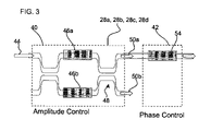
- FIG. 3 illustrates details of the phase shifters 28 a , 28 b , 28 c , 28 d , also referred to as 12 a , 12 b . . . 12 n in FIG. 1 , used to control the relative energy and phase in each waveguide, receiving a light beam from the single-mode waveguide 6 .
- the phase shifters 28 a , 28 b , 28 c , 28 d include an amplitude control 40 and a phase control 42 .
- the amplitude control 40 receives an input light 44 from a source that passes through heaters 46 a , 46 b that control the local phase of the light 44 .
- the light 44 then passes through a 50—50 coupler 48 which produces output beams 50 a , 50 b , where output 52 b is light that is drained and not used.
- the coupler 48 couples lines together from different waveguides.
- Light 50 b comprises dissipated light.
- the amplitude control 40 adjusts the amplitude of the output light 50 a .
- the phase control 42 includes a heater 54 that applies energy to the light 50 a passing through to set the phase of the light.
- FIGS. 4 a – 4 d illustrate examples of different shapes of the beams 40 , 42 , 44 , and 46 , respectively, that may be created by adjusting the phase and amplitude of the light beam reflected off the gratings 24 a , 24 b . . . 24 n by controlling the voltages applied by the phase shifters 28 a , 28 b . . . 28 n .
- FIGS. 4 a , 4 b , and 4 c illustrates how the beam can be apodized in phase and amplitude to create a flat-top profile, or a “Bessel-like” beam for diffraction-less propagation controlled in different directions.
- FIG. 4 c illustrates that the beam is created by using a grating diffraction angle ⁇ y.
- FIG. 4 d provides an example of how the phase shifters 28 a , 28 b . . . 28 n may be controlled to focus the beam.
- FIG. 1 additionally illustrates how the optical device 2 may be used in reverse to collect light through the Bragg gratings that is deflected into a detector 14 .
- the directivity of this receiving optical antenna may be tailored in the same way described above when the optical device 2 functions as a transmitter.
- the phases can be configured to “null” out light received from certain directions at the gratings.
- a circulator or splitter is attached to the optical device 2 with the detector 14 , the optical device 2 can be used to send light and receive light simultaneously, i.e. a transceiver.
- a mirror or reflective Bragg grating
- FIG. 5 illustrates a system comprised of two devices 100 a , 100 b each including a substrate 102 a , 102 b , which may be implemented on an integrated circuit die, forming a surface having a plurality of elements 104 a , 104 , where each element in the array of elements 104 a , 104 b may comprise an optical device 2 shown in FIG. 1 .
- Multiple elements in the array of elements 104 a communicates light beams to elements in the array of elements 104 b acting as a receiver.
- the arrays of elements 104 a , 104 b may comprise transceivers and both transmit and receive light beams 106 therebetween.
- device 100 b may include a memory device 108 , such as a volatile or non-volatile memory device, to store data encoded in the light beams communicated from the device 100 a .
- device 100 a may include a memory device to store data encoded in light transmitted from device 100 b .
- the substrates 102 a , 102 b may comprise integrated circuits.
- the devices 100 a , 100 b may include multiple substrates, each having an array of elements, forming a larger scale array distributed across multiple integrated circuit substrates.
- the devices 100 a , 100 b may comprise a communication device in a stationary location, such as in a building, etc. Alternatively, the devices 100 a , 100 b may be integrated in a moving device, such as a ship, automobile, etc. In implementations, where the devices 100 a , 100 b are included in systems that move, the elements in the arrays 104 a , 104 b may be programmable to allow the transmitter and receiver elements to adjust their phase in the event the arrays 104 a , 104 b change their position. The phase of the transmitter and receiver arrays 104 a , 104 b may be adjusted to allow the receiver array 104 b to remain locked on or continue receiving the beam from the transmitter array 104 a .
- the devices 100 a , 100 b may comprise communication systems, such as transmitters and receivers or modems to enable wireless transmission and reception.
- the described embodiments provide an optical device implementing a phased array in the optical domain to maintain a fixed and coherent phase relationship of light and that can be used for dynamic (or static) shaping of coherent optical beams for laser beam delivery or high directivity optical telescopes.
- the optical device of the described embodiments may comprise a small form factor pseudo-dimensional structure enabled to make a large area structure coherent optical array with high optical power capacity.
- the described embodiments use blazed waveguide Bragg gratings, or other suitable gratings known in the art, which can be patterned with prescribed phase and amplitude functions for biasing the beam shape and creating beams with reduced side lobes.
- Described embodiments provide for increased frequency over RF phased arrays allowing for communication at greatly increased bandwidths compared to an RF phased array antenna and with higher directivity.
- the described optical device may be integrated in a photonic integrated circuit with other functionalities such as on-chip optical amplification, switching, and wavelength filtering.
- the described embodiments may enable optical chip-to-chip communication with quick switching/beam steering, may allow for reading/writing to optical memory using beam steering, may allow for viable laser space communication, and may provide a small light-weight large-area laser/receiver.
Abstract
Description
Claims (30)
Priority Applications (1)
| Application Number | Priority Date | Filing Date | Title |
|---|---|---|---|
| US10/981,306 US7095925B2 (en) | 2004-11-03 | 2004-11-03 | Optical phased array transmitter/receiver |
Applications Claiming Priority (1)
| Application Number | Priority Date | Filing Date | Title |
|---|---|---|---|
| US10/981,306 US7095925B2 (en) | 2004-11-03 | 2004-11-03 | Optical phased array transmitter/receiver |
Publications (2)
| Publication Number | Publication Date |
|---|---|
| US20060091305A1 US20060091305A1 (en) | 2006-05-04 |
| US7095925B2 true US7095925B2 (en) | 2006-08-22 |
Family
ID=36260728
Family Applications (1)
| Application Number | Title | Priority Date | Filing Date |
|---|---|---|---|
| US10/981,306 Expired - Fee Related US7095925B2 (en) | 2004-11-03 | 2004-11-03 | Optical phased array transmitter/receiver |
Country Status (1)
| Country | Link |
|---|---|
| US (1) | US7095925B2 (en) |
Cited By (15)
| Publication number | Priority date | Publication date | Assignee | Title |
|---|---|---|---|---|
| US20060013108A1 (en) * | 2004-06-25 | 2006-01-19 | Maxwell Ian A | Information storage system and method |
| US8059254B1 (en) | 2008-06-04 | 2011-11-15 | Raytheon Company | Transparent heatsink/structure/interconnect for tiling space based optical components |
| US8228293B2 (en) | 2005-09-14 | 2012-07-24 | Nintendo Co., Ltd. | Remote control and system and method using the remote control |
| US20130003514A1 (en) * | 2011-07-01 | 2013-01-03 | Meinolf Blawat | Method and apparatus for data storage |
| WO2013078435A1 (en) * | 2011-11-21 | 2013-05-30 | California Institute Of Technology | Integrated optical phased arrays |
| CN105026970A (en) * | 2013-01-08 | 2015-11-04 | 麻省理工学院 | Optical phased arrays |
| US9621281B2 (en) | 2014-11-18 | 2017-04-11 | Qualcomm Incorporated | Integrated device package and/or system comprising configurable directional optical transmitter |
| CN106575017A (en) * | 2014-06-30 | 2017-04-19 | 奎纳吉系统公司 | Planar beam forming and steering optical phased array chip and method of using same |
| US9632345B2 (en) | 2012-05-24 | 2017-04-25 | Raytheon Company | Liquid crystal control structure, tip-tilt-focus optical phased array and high power adaptive optic |
| US9835856B2 (en) | 2013-05-24 | 2017-12-05 | Raytheon Company | Adaptive optic having meander resistors |
| US10365536B1 (en) * | 2018-02-07 | 2019-07-30 | Eagle Technology, Llc | Optical device including a monolithic body of optical material and related methods |
| US10613410B2 (en) | 2016-10-14 | 2020-04-07 | Analog Photonics LLC | Large scale optical phased array |
| US20200256958A1 (en) * | 2019-02-07 | 2020-08-13 | Pointcloud Inc. | Ranging using a shared path optical coupler |
| US20210318440A1 (en) * | 2020-04-10 | 2021-10-14 | Caterpillar Paving Products Inc. | Perception system three lidar coverage |
| US11808934B2 (en) | 2021-04-20 | 2023-11-07 | Eagle Technology, Llc | Planar optical telescope and related methods |
Families Citing this family (14)
| Publication number | Priority date | Publication date | Assignee | Title |
|---|---|---|---|---|
| US8358888B2 (en) * | 2008-04-10 | 2013-01-22 | Ofs Fitel, Llc | Systems and techniques for generating Bessel beams |
| US20120068880A1 (en) * | 2010-09-17 | 2012-03-22 | Raytheon Company | System and Method for Dual-Band Antenna Pointing, Acquisition, And Tracking |
| US9476981B2 (en) * | 2013-01-08 | 2016-10-25 | Massachusetts Institute Of Technology | Optical phased arrays |
| US9869753B2 (en) * | 2014-08-15 | 2018-01-16 | Quanergy Systems, Inc. | Three-dimensional-mapping two-dimensional-scanning lidar based on one-dimensional-steering optical phased arrays and method of using same |
| US10036803B2 (en) | 2014-10-20 | 2018-07-31 | Quanergy Systems, Inc. | Three-dimensional lidar sensor based on two-dimensional scanning of one-dimensional optical emitter and method of using same |
| US10062946B2 (en) * | 2016-01-05 | 2018-08-28 | Psemi Corporation | Reflection-based RF phase shifter |
| US9893816B2 (en) | 2016-03-25 | 2018-02-13 | Intel Corporation | Dynamic beam steering optoelectronic packages |
| KR102251273B1 (en) * | 2016-12-16 | 2021-05-14 | 더 차레스 스타크 드레이퍼 래보레이토리, 인코포레이티드 | All solid state optical transmit/receive terminal |
| CN108693505A (en) * | 2017-06-09 | 2018-10-23 | 深圳市涵光半导体有限公司 | Laser radar and its phased-array laser transmitter unit |
| WO2019010621A1 (en) * | 2017-07-11 | 2019-01-17 | 深圳市涵光半导体有限公司 | Phased array laser radar |
| DE102018105607B4 (en) * | 2018-03-12 | 2022-05-25 | Sick Ag | Photoelectric sensor and method for detecting objects in a surveillance area |
| CN110044394A (en) * | 2019-05-08 | 2019-07-23 | 浙江大学昆山创新中心 | A kind of novel light wave leads phase-array scanning system |
| DE102019124266A1 (en) | 2019-09-10 | 2021-03-11 | Sick Ag | Optoelectronic sensor and method for detecting objects in a surveillance area |
| US11609478B2 (en) * | 2020-06-11 | 2023-03-21 | Hirose Electric Co., Ltd. | Systems and methods for alignment of photonic integrated circuits and printed optical boards |
Citations (35)
| Publication number | Priority date | Publication date | Assignee | Title |
|---|---|---|---|---|
| US4726011A (en) * | 1985-04-08 | 1988-02-16 | Itt Defense Communications, A Division Of Itt Corporation | Coherent optical fiber communication with frequency-division-multiplexing |
| US5077816A (en) * | 1989-12-26 | 1991-12-31 | United Technologies Corporation | Fiber embedded grating frequency standard optical communication devices |
| US5093876A (en) * | 1990-07-27 | 1992-03-03 | At&T Bell Laboratories | WDM systems incorporating adiabatic reflection filters |
| US5450511A (en) * | 1992-04-29 | 1995-09-12 | At&T Corp. | Efficient reflective multiplexer arrangement |
| US5457760A (en) * | 1994-05-06 | 1995-10-10 | At&T Ipm Corp. | Wavelength division optical multiplexing elements |
| US5570440A (en) * | 1993-06-17 | 1996-10-29 | At&T Corp. | Optical waveguiding component comprising a band-pass filter |
| US5608825A (en) * | 1996-02-01 | 1997-03-04 | Jds Fitel Inc. | Multi-wavelength filtering device using optical fiber Bragg grating |
| US5627927A (en) * | 1992-10-20 | 1997-05-06 | Mcdonnell Douglas Aerospace West | Fiber with multiple overlapping gratings |
| US5638473A (en) * | 1994-11-16 | 1997-06-10 | Northern Telecom Limited | Optical waveguide grating filter |
| US5680489A (en) * | 1996-06-28 | 1997-10-21 | The United States Of America As Represented By The Secretary Of The Navy | Optical sensor system utilizing bragg grating sensors |
| US5748350A (en) * | 1996-06-19 | 1998-05-05 | E-Tek Dynamics, Inc. | Dense wavelength division multiplexer and demultiplexer devices |
| US5793907A (en) * | 1996-03-28 | 1998-08-11 | The Regents Of The University Of California | Method and apparatus for a wavelength selective true-time delay for an optically controlled device |
| US5818585A (en) * | 1997-02-28 | 1998-10-06 | The United States Of America As Represented By The Secretary Of The Navy | Fiber Bragg grating interrogation system with adaptive calibration |
| US5825520A (en) * | 1992-07-27 | 1998-10-20 | Huber; David R. | Optical demultiplexers with grating reflectors |
| US5982334A (en) | 1997-10-31 | 1999-11-09 | Waveband Corporation | Antenna with plasma-grating |
| US5982516A (en) * | 1994-09-20 | 1999-11-09 | Bicc Public Limited Company | Optical network with wavelength-dependent routing |
| US5987197A (en) * | 1997-11-07 | 1999-11-16 | Cidra Corporation | Array topologies for implementing serial fiber Bragg grating interferometer arrays |
| US6014480A (en) * | 1997-11-21 | 2000-01-11 | Hewlett-Packard Company | Optical energy selector apparatus and method |
| US6041070A (en) * | 1997-11-14 | 2000-03-21 | Sdl, Inc. | Resonant pumped short cavity fiber laser |
| US6137442A (en) * | 1998-04-01 | 2000-10-24 | The United States Of America As Represented By The Secretary Of The Navy | Chirped fiber grating beamformer for phased array antennas |
| US6292282B1 (en) * | 1998-08-10 | 2001-09-18 | Templex Technology, Inc. | Time-wavelength multiple access optical communication systems and methods |
| US6314220B1 (en) * | 1995-03-13 | 2001-11-06 | Templex Technology, Inc. | Segmented complex fiber gratings |
| US6313771B1 (en) * | 1999-11-17 | 2001-11-06 | Templex Technology, Inc. | Codes, methods, and apparatus for optical encoding and decoding |
| US20020030877A1 (en) * | 2000-03-07 | 2002-03-14 | Winston Way | Method and apparatus for interleaved optical single sideband modulation |
| US6449073B1 (en) * | 1998-07-21 | 2002-09-10 | Corvis Corporation | Optical communication system |
| US6456762B1 (en) * | 1999-12-09 | 2002-09-24 | Oki Electric Industry Co., Ltd. | Method of fabricating optical waveguide device |
| US20020163696A1 (en) * | 2000-06-23 | 2002-11-07 | Jen-Fa Huang | Fiber bragg grating-based optical CDMA encoder/decoder |
| US6485413B1 (en) | 1991-04-29 | 2002-11-26 | The General Hospital Corporation | Methods and apparatus for forward-directed optical scanning instruments |
| US6522797B1 (en) * | 1998-09-01 | 2003-02-18 | Input/Output, Inc. | Seismic optical acoustic recursive sensor system |
| US6594421B1 (en) | 1999-01-26 | 2003-07-15 | Intel Corporation | Dynamically reconfigurable composite grating filters for temporal waveform processing |
| US6765681B1 (en) | 2001-04-10 | 2004-07-20 | Intel Corporation | Measuring optical phase |
| US6778102B1 (en) * | 1999-06-11 | 2004-08-17 | Intel Corporation | Communication system and apparatus with synchronous orthogonal coding |
| US6807372B1 (en) * | 2000-07-14 | 2004-10-19 | University Of Maryland | Integrated spectral encoder/decoder for optical CDMA communication system |
| US6865344B1 (en) * | 1999-11-12 | 2005-03-08 | Intel Corporation | Code-switched optical networks |
| US20050089328A1 (en) * | 2002-11-20 | 2005-04-28 | Akihiko Nishiki | Optical signal converter, optical encoder, optical decoder, and optical code division multiplexing communication apparatus |
-
2004
- 2004-11-03 US US10/981,306 patent/US7095925B2/en not_active Expired - Fee Related
Patent Citations (37)
| Publication number | Priority date | Publication date | Assignee | Title |
|---|---|---|---|---|
| US4726011A (en) * | 1985-04-08 | 1988-02-16 | Itt Defense Communications, A Division Of Itt Corporation | Coherent optical fiber communication with frequency-division-multiplexing |
| US5077816A (en) * | 1989-12-26 | 1991-12-31 | United Technologies Corporation | Fiber embedded grating frequency standard optical communication devices |
| US5093876A (en) * | 1990-07-27 | 1992-03-03 | At&T Bell Laboratories | WDM systems incorporating adiabatic reflection filters |
| US6485413B1 (en) | 1991-04-29 | 2002-11-26 | The General Hospital Corporation | Methods and apparatus for forward-directed optical scanning instruments |
| US5450511A (en) * | 1992-04-29 | 1995-09-12 | At&T Corp. | Efficient reflective multiplexer arrangement |
| US5825520A (en) * | 1992-07-27 | 1998-10-20 | Huber; David R. | Optical demultiplexers with grating reflectors |
| US5627927A (en) * | 1992-10-20 | 1997-05-06 | Mcdonnell Douglas Aerospace West | Fiber with multiple overlapping gratings |
| US5570440A (en) * | 1993-06-17 | 1996-10-29 | At&T Corp. | Optical waveguiding component comprising a band-pass filter |
| US5457760A (en) * | 1994-05-06 | 1995-10-10 | At&T Ipm Corp. | Wavelength division optical multiplexing elements |
| US5982516A (en) * | 1994-09-20 | 1999-11-09 | Bicc Public Limited Company | Optical network with wavelength-dependent routing |
| US5638473A (en) * | 1994-11-16 | 1997-06-10 | Northern Telecom Limited | Optical waveguide grating filter |
| US6314220B1 (en) * | 1995-03-13 | 2001-11-06 | Templex Technology, Inc. | Segmented complex fiber gratings |
| US5608825A (en) * | 1996-02-01 | 1997-03-04 | Jds Fitel Inc. | Multi-wavelength filtering device using optical fiber Bragg grating |
| US5793907A (en) * | 1996-03-28 | 1998-08-11 | The Regents Of The University Of California | Method and apparatus for a wavelength selective true-time delay for an optically controlled device |
| US5748350A (en) * | 1996-06-19 | 1998-05-05 | E-Tek Dynamics, Inc. | Dense wavelength division multiplexer and demultiplexer devices |
| US5680489A (en) * | 1996-06-28 | 1997-10-21 | The United States Of America As Represented By The Secretary Of The Navy | Optical sensor system utilizing bragg grating sensors |
| US5818585A (en) * | 1997-02-28 | 1998-10-06 | The United States Of America As Represented By The Secretary Of The Navy | Fiber Bragg grating interrogation system with adaptive calibration |
| US5982334A (en) | 1997-10-31 | 1999-11-09 | Waveband Corporation | Antenna with plasma-grating |
| US5987197A (en) * | 1997-11-07 | 1999-11-16 | Cidra Corporation | Array topologies for implementing serial fiber Bragg grating interferometer arrays |
| US6041070A (en) * | 1997-11-14 | 2000-03-21 | Sdl, Inc. | Resonant pumped short cavity fiber laser |
| US6295304B1 (en) * | 1997-11-14 | 2001-09-25 | Sdl, Inc. | Resonant pumped short cavity fiber laser with multiple optical resonators |
| US6014480A (en) * | 1997-11-21 | 2000-01-11 | Hewlett-Packard Company | Optical energy selector apparatus and method |
| US6137442A (en) * | 1998-04-01 | 2000-10-24 | The United States Of America As Represented By The Secretary Of The Navy | Chirped fiber grating beamformer for phased array antennas |
| US6449073B1 (en) * | 1998-07-21 | 2002-09-10 | Corvis Corporation | Optical communication system |
| US6292282B1 (en) * | 1998-08-10 | 2001-09-18 | Templex Technology, Inc. | Time-wavelength multiple access optical communication systems and methods |
| US6522797B1 (en) * | 1998-09-01 | 2003-02-18 | Input/Output, Inc. | Seismic optical acoustic recursive sensor system |
| US6591025B1 (en) * | 1998-09-01 | 2003-07-08 | Input/Output, Inc. | Optical sensing system |
| US6594421B1 (en) | 1999-01-26 | 2003-07-15 | Intel Corporation | Dynamically reconfigurable composite grating filters for temporal waveform processing |
| US6778102B1 (en) * | 1999-06-11 | 2004-08-17 | Intel Corporation | Communication system and apparatus with synchronous orthogonal coding |
| US6865344B1 (en) * | 1999-11-12 | 2005-03-08 | Intel Corporation | Code-switched optical networks |
| US6313771B1 (en) * | 1999-11-17 | 2001-11-06 | Templex Technology, Inc. | Codes, methods, and apparatus for optical encoding and decoding |
| US6456762B1 (en) * | 1999-12-09 | 2002-09-24 | Oki Electric Industry Co., Ltd. | Method of fabricating optical waveguide device |
| US20020030877A1 (en) * | 2000-03-07 | 2002-03-14 | Winston Way | Method and apparatus for interleaved optical single sideband modulation |
| US20020163696A1 (en) * | 2000-06-23 | 2002-11-07 | Jen-Fa Huang | Fiber bragg grating-based optical CDMA encoder/decoder |
| US6807372B1 (en) * | 2000-07-14 | 2004-10-19 | University Of Maryland | Integrated spectral encoder/decoder for optical CDMA communication system |
| US6765681B1 (en) | 2001-04-10 | 2004-07-20 | Intel Corporation | Measuring optical phase |
| US20050089328A1 (en) * | 2002-11-20 | 2005-04-28 | Akihiko Nishiki | Optical signal converter, optical encoder, optical decoder, and optical code division multiplexing communication apparatus |
Non-Patent Citations (14)
| Title |
|---|
| "Polymer-based Guided Wave True-time Delay Module for Phased Array Atenna", [online], [Retrieved on Aug. 22, 2004], retrieved from the Internet at <URL: http://www.ece.utexas.edu/projects/ec/mrc/groups/optic-inter/Phased<SUB>-</SUB>Array<SUB>-</SUB>Antenna.htm>. |
| Chiaro Networks, "Optical Phased Array Technology for High-Speed Switching", 2002, pp. 1-7. |
| Grunnet-Jepsen et al, "Demonstration of All-Fiber Sparse Lightwave CDMA Based on Temporal Phase Encoding", IEEE Photonics Tech Letters, vol. 11, No. 10, Oct. 1999. * |
| Grunnet-Jepson, A., A.E. Johnson, E.S. Maniloff, T.W. Mossberg, M.I. Munroe, & J.N. Sweetser, "Demonstartion of All-Fiber Sparse Lightwave CDMA Based on Temporal Phase Encoding", IEEE Photonics Technology Letters, vol. 11, No. 10, Oct. 1999, pp. 1283-1285. |
| Huang et al, "Fiber-Grating Based Optical CDMA . . . ", IEEE Photonics Tech. Letters, vol. 12, No. 9, Sep. 2000. * |
| Huang et al, "Optical Spectral-Amplitude Coder/Decoders . . . ", IEEE, Jun. 2004. * |
| Huang, J. C. Tsai, & M. Kang, "Optical Spectral-Amplitude Coder/Decoders Structured with Circulator-Free Fiber-Gratings Array", 2004, pp. 550-554. |
| Huang, J., and D. Hsu, "Fiber-Grating Based Optical CDMA Spectral Coding with Nearly Orthogonal M-Sequence Codes", IEEE Photonics Technology Letters, vol. 12, No. 9, Sep. 2000, pp. 1252-1254. |
| Skolnik, M.I., "Introducing Radar Systems", Third Edition, 2001, pp. 559-589. |
| Teh et al, "A Comparative Study of the Performance of Seven-and 63-Chip . . . ", Journal of Lightwave Tech., vol. 19, No. 9, Sep. 2001. * |
| Teh et al, "Phase Encoding and Decoding of Short Pulse . . . ", IEEE Photonics Tech. Letters, vol. 13, No. 2, Feb. 2001. * |
| Teh, P.C., P. Petropoulos, M. Ibsen, D.J. Richardson, "A Comparative Study of the Performance of Seven-and 63-Chip Optical Code-Division Multiple-Access Encoders and Decoders Based on Superstructured Fiber Bragg Gratings", Journal of Lightwave Technology, vol. 19, No. 9, Sep. 2001, pp. 1352-1365. |
| Teh, P.C., P. Petropoulos, M. Isben, & D.J. Richardson, "Phase Encoding and Decoding of Short Pulses at 10 Gb/s Using Superstructured Fiber Bragg Gratings", IEEE Photonics Technology Letters, vol. 13, No. 2, Feb. 2001. |
| Wang, M., B. Wang, J. Anderson, P.J. Bos, & P.P. McManamon, "Optical Phased Array Technology for Beam Steering and Wavefront Control", Mar. 7, 2003. |
Cited By (24)
| Publication number | Priority date | Publication date | Assignee | Title |
|---|---|---|---|---|
| US20060013108A1 (en) * | 2004-06-25 | 2006-01-19 | Maxwell Ian A | Information storage system and method |
| US8228293B2 (en) | 2005-09-14 | 2012-07-24 | Nintendo Co., Ltd. | Remote control and system and method using the remote control |
| US8059254B1 (en) | 2008-06-04 | 2011-11-15 | Raytheon Company | Transparent heatsink/structure/interconnect for tiling space based optical components |
| US8988977B2 (en) * | 2011-07-01 | 2015-03-24 | Thomson Licensing | Method and apparatus for data storage |
| US20130003514A1 (en) * | 2011-07-01 | 2013-01-03 | Meinolf Blawat | Method and apparatus for data storage |
| US9124373B2 (en) | 2011-11-21 | 2015-09-01 | California Institute Of Technology | Integrated optical phased array |
| WO2013078435A1 (en) * | 2011-11-21 | 2013-05-30 | California Institute Of Technology | Integrated optical phased arrays |
| US9632345B2 (en) | 2012-05-24 | 2017-04-25 | Raytheon Company | Liquid crystal control structure, tip-tilt-focus optical phased array and high power adaptive optic |
| CN105026970B (en) * | 2013-01-08 | 2020-04-07 | 麻省理工学院 | Optical phased array |
| CN105026970A (en) * | 2013-01-08 | 2015-11-04 | 麻省理工学院 | Optical phased arrays |
| US9835856B2 (en) | 2013-05-24 | 2017-12-05 | Raytheon Company | Adaptive optic having meander resistors |
| CN106575017A (en) * | 2014-06-30 | 2017-04-19 | 奎纳吉系统公司 | Planar beam forming and steering optical phased array chip and method of using same |
| CN106575017B (en) * | 2014-06-30 | 2020-01-14 | 奎纳吉系统公司 | Planar beamforming and steering optical phased array chips and methods of using the same |
| US9621281B2 (en) | 2014-11-18 | 2017-04-11 | Qualcomm Incorporated | Integrated device package and/or system comprising configurable directional optical transmitter |
| US10613410B2 (en) | 2016-10-14 | 2020-04-07 | Analog Photonics LLC | Large scale optical phased array |
| US10365536B1 (en) * | 2018-02-07 | 2019-07-30 | Eagle Technology, Llc | Optical device including a monolithic body of optical material and related methods |
| US20200256958A1 (en) * | 2019-02-07 | 2020-08-13 | Pointcloud Inc. | Ranging using a shared path optical coupler |
| WO2020163717A1 (en) * | 2019-02-07 | 2020-08-13 | Pointcloud Inc. | Ranging using a shared path optical coupler |
| US11619710B2 (en) * | 2019-02-07 | 2023-04-04 | Pointcloud Inc. | Ranging using a shared path optical coupler |
| US20230221421A1 (en) * | 2019-02-07 | 2023-07-13 | Pointcloud Inc. | Ranging using a shared path optical coupler |
| US11789124B2 (en) * | 2019-02-07 | 2023-10-17 | Pointcloud Inc. | Ranging using a shared path optical coupler |
| US20210318440A1 (en) * | 2020-04-10 | 2021-10-14 | Caterpillar Paving Products Inc. | Perception system three lidar coverage |
| US11550058B2 (en) * | 2020-04-10 | 2023-01-10 | Caterpillar Paving Products Inc. | Perception system three lidar coverage |
| US11808934B2 (en) | 2021-04-20 | 2023-11-07 | Eagle Technology, Llc | Planar optical telescope and related methods |
Also Published As
| Publication number | Publication date |
|---|---|
| US20060091305A1 (en) | 2006-05-04 |
Similar Documents
| Publication | Publication Date | Title |
|---|---|---|
| US7095925B2 (en) | Optical phased array transmitter/receiver | |
| US6760512B2 (en) | Electro-optical programmable true-time delay generator | |
| US7729572B1 (en) | Optical tapped time delay modules and arrays | |
| US10613410B2 (en) | Large scale optical phased array | |
| US5796510A (en) | Ladder-structured photonic variable delay device | |
| USRE41954E1 (en) | Optical time delay apparatus incorporating diffractive element sets | |
| US5761351A (en) | Wavelength-addressable optical time-delay network and phased array antenna incorporating the same | |
| US5583516A (en) | Wavelength-selectable optical signal processor | |
| US6393177B2 (en) | True time delay generating system and method | |
| WO2001097326A1 (en) | Fiber-optic, wideband array antenna beamformer | |
| WO2017218291A1 (en) | Wide angle steering with phase array with wide-element spacing and lens array | |
| US6295395B1 (en) | True time delay generation utilizing broadband light source with fiber chirp grating array and acousto-optic beam steering and 2-D architectures | |
| Lembo et al. | Low-loss fiber optic time-delay element for phased-array antennas | |
| Srivastava et al. | Efficient photonic beamforming system incorporating a unique featured tunable chirped fiber bragg grating for application extended to the Ku-band | |
| Kumar et al. | Efficient 2D optical beamforming network with sub partitioning capability based on raised cosine chirped fiber grating and Mach-Zehnder delay interferometer | |
| Srivastava et al. | Demonstration of highly steerable beamforming system incorporating a waveguide of spatially distributed fiber Bragg grating | |
| CN100365471C (en) | Optical phase array device | |
| Wickham et al. | Fiber optic Bragg grating true-time-delay generator for broadband rf applications | |
| Thai et al. | A novel simplified dual beam-former using multichannel chirped fiber grating and tunable optical delay lines | |
| JP2000114851A (en) | Optically controlled phased array antenna | |
| Fu et al. | Five-bit substrate guided wave true-time delay module working up to 2.4 Thz with a packing density of 2.5 lines/cm2 for phased array antenna applications | |
| Juswardy et al. | Photonic true-time delay unit for broadband adaptive nulling in antenna arrays | |
| Xiao et al. | Opto-VLSI-Based Beamformer for radio-frequency phased-array antennas | |
| CN113568095A (en) | Wide-body surface grating, antenna system thereof and laser radar three-dimensional scanning system | |
| Caso et al. | Practical impairments in FBG-based true time delays |
Legal Events
| Date | Code | Title | Description |
|---|---|---|---|
| AS | Assignment |
Owner name: INTEL CORPORATION, CALIFORNIA Free format text: ASSIGNMENT OF ASSIGNORS INTEREST;ASSIGNORS:GRUNNET-JEPSON, ANDERS;SWEETSER, JOHN;JOHNSON, ALAN;REEL/FRAME:015979/0825;SIGNING DATES FROM 20041014 TO 20041102 |
|
| CC | Certificate of correction | ||
| FPAY | Fee payment |
Year of fee payment: 4 |
|
| FPAY | Fee payment |
Year of fee payment: 8 |
|
| FEPP | Fee payment procedure |
Free format text: MAINTENANCE FEE REMINDER MAILED (ORIGINAL EVENT CODE: REM.) |
|
| LAPS | Lapse for failure to pay maintenance fees |
Free format text: PATENT EXPIRED FOR FAILURE TO PAY MAINTENANCE FEES (ORIGINAL EVENT CODE: EXP.); ENTITY STATUS OF PATENT OWNER: LARGE ENTITY |
|
| STCH | Information on status: patent discontinuation |
Free format text: PATENT EXPIRED DUE TO NONPAYMENT OF MAINTENANCE FEES UNDER 37 CFR 1.362 |
|
| FP | Lapsed due to failure to pay maintenance fee |
Effective date: 20180822 |