US7089930B2 - Wireless heads-up display for a self-contained breathing apparatus - Google Patents
Wireless heads-up display for a self-contained breathing apparatus Download PDFInfo
- Publication number
- US7089930B2 US7089930B2 US10/224,527 US22452702A US7089930B2 US 7089930 B2 US7089930 B2 US 7089930B2 US 22452702 A US22452702 A US 22452702A US 7089930 B2 US7089930 B2 US 7089930B2
- Authority
- US
- United States
- Prior art keywords
- breathing gas
- transmitter
- receiver
- controller
- display system
- Prior art date
- Legal status (The legal status is an assumption and is not a legal conclusion. Google has not performed a legal analysis and makes no representation as to the accuracy of the status listed.)
- Expired - Lifetime, expires
Links
Images


Classifications
-
- A—HUMAN NECESSITIES
- A62—LIFE-SAVING; FIRE-FIGHTING
- A62B—DEVICES, APPARATUS OR METHODS FOR LIFE-SAVING
- A62B9/00—Component parts for respiratory or breathing apparatus
- A62B9/006—Indicators or warning devices, e.g. of low pressure, contamination
Definitions
- the invention relates generally to a Self-Contained Breathing Apparatus (hereinafter SCBA), and more particularly, to a heads-up display for monitoring various parameters of interest to the wearer including, for example, the level of breathing gas in the SCBA.
- SCBA Self-Contained Breathing Apparatus
- SCBAs are typically used to provide a safe breathing gas supply to a wearer thereof.
- SCBAs typically include a breathing mask in fluid communication with a breathing gas supply such as, for example, a breathing gas tank.
- SCBAs are commonly employed by, for example, firefighters and others, when fighting fires or working within environments that contain hazardous gases, microbes or other airborne contaminants. As such, it is vital that the amount of breathing gas remaining in the breathing gas supply be known while the SCBA is in use.
- One method of presenting this information to the SCBA wearer has been through a mechanical gauge that typically hangs down from the left or right shoulder of the SCBA wearer.
- U.S. Pat. No. 5,097,826 provides a pressure monitoring device for a SCBA that includes visual indicators disposed in the SCBA wearer's field of view to monitor when predetermined pressure levels are reached in the breathing gas supply.
- the connection between the pressure sensing device and the visual indicators in this and other pressure monitoring devices is typically accomplished through a cable or chord.
- cables and chords are notorious safety and reliability risks in firefighting and other situations where SCBAs are worn. Firefighters often crawl through narrow spaces and cables or chords can get snagged, broken or torn.
- a pressure monitoring device for SCBAs that does not suffer from the aforementioned drawbacks is highly desirable.
- a breathing gas monitor for a breathing apparatus includes a transmitter and receiver or a transceiver.
- the transmitter has a pressure sensor configured to sense the pressure level of breathing gas associated with a breathing gas supply and a controller in circuit communication with the pressure sensor and configured to transmit either intermittently or continuously a breathing gas level via a radio frequency signal to the receiver.
- the receiver has a radio frequency circuit or controller configured to receive the radio frequency signals generated by the transmitter and a display in circuit communication therewith that is configured to indicate the breathing gas level associated with the breathing gas supply to the wearer of the breathing apparatus.
- FIG. 1 is a functional block diagram of one embodiment of a system of the present invention.
- FIG. 2 is a drawing illustrating one embodiment of an antenna of the present invention.
- FIGS. 3A and 3B are a flowchart illustrating one embodiment of the transmitter logic of the present invention.
- FIG. 4 is a diagram illustrating one embodiment of a transmission signal.
- FIGS. 5A and 5B are a flowchart illustrating one embodiment of the receiver logic of the present invention.
- FIGS. 6A and 6B illustrate one embodiment of SCBA system of the present invention.
- FIGS. 7A and 7B illustrate one embodiment of a heads-up receiver and display of the present invention.
- FIGS. 8A , 8 B, and 8 C illustrate one embodiment of a pressure transmitter of the present invention.
- Logic includes but is not limited to hardware, firmware, software and/or combinations of each to perform a function(s) or an action(s), and/or to cause a function or action from another component.
- logic may include a software controlled microprocessor, discrete logic such as an application specific integrated circuit (ASIC), or other programmed logic device.
- ASIC application specific integrated circuit
- Logic may also be fully embodied as software.
- Signal includes one or more electrical, optical, or electromagnetic signals, analog or digital signals, one or more computer instructions, a bit or bit stream, or the like.
- Software includes but is not limited to one or more computer readable and/or executable instructions that cause a computer or other electronic device to perform functions, actions, and/or behave in a desire manner.
- the instructions may be embodied in various forms such as routines, algorithms, modules or programs including separate applications or code from dynamically linked libraries.
- Software may also be implemented in various forms such as a stand-alone program, a function call, a servlet, an applet, instructions stored in a memory, part of an operating system or other type of executable instructions. It will be appreciated by one of ordinary skill in the art that the form of software is dependent on, for example, requirements of a desired application, the environment it runs on, and/or the desires of a designer/programmer or the like.
- Controller includes but is not limited to any circuit or device that coordinates and controls the operation of one or more input and/or output devices.
- a controller can include a device having one or more microprocessors or central processing units capable of being programmed to perform input and/or output functions.
- FIG. 1 Illustrated in FIG. 1 is a block diagram of a system 100 of one embodiment of the present invention.
- System 100 has a transmitter 102 and a receiver 104 .
- the transmitter 102 is preferably configured as a pressure transmitter and has a controller 106 , transmitter logic 108 , battery 110 , pressure sensor 112 , power amplifier 114 , and antenna 116 .
- controller 106 is a microprocessor-based controller having a memory, watchdog timer, and one or more input/output ports including an analog-to-digital converter.
- Transmitter logic 108 preferably resides within the memory of controller 106 and is configured to interpret an analog pressure signal produced by pressure sensor 112 and to generate a breathing gas level signal that is to be transmitted to receiver 104 .
- transmitter logic 108 can reside in an external memory readable by controller 106 .
- An instrumentation amplifier or other signal conditioning circuitry 113 can be incorporated between the sensor 112 and controller 106 .
- the breathing gas level signal is indicative of the amount of breathing gas remaining in a breathing gas supply, such as a breathing gas tank of a SCBA.
- controller 106 and logic 108 modulate this information onto a radio frequency carrier through any one of a plurality of suitable modulation techniques creating a communication channel having a baud rate of, for example, 1800 baud.
- suitable modulation techniques include Frequency Shift Keying (FSK) and On-Off keying modulation.
- FSK modulation uses at least 2 distinct frequencies to transmit a digital signal.
- One frequency represents a digital “1” bit and a second frequency represents a digital “0” bit.
- Receiver 104 detects these changes in frequency and reconstructs the digital word.
- One example of using two distinct frequencies includes using a frequency in the range of 30–70 kHz that is frequency shifted by +/ ⁇ 1800 Hz to generate the “1” and “0” bits.
- On-Off keying modulation employs one signal to transmit the digital “1” bit and the absence of a signal to transmit the digital “0” bit.
- a transmission according to one embodiment of the present invention includes a transmission having an initialization that includes a long series of “1” bits to signal the start of the transmission.
- One representative transmission signal of the present invention is discussed in more detail in connection with FIG. 4 .
- the breathing gas level signal is output to amplifier 114 , which drives antenna 116 to generate a radio frequency transmission signal 118 .
- Antenna 116 is preferably a loop stick antenna, which will be discussed in more detail in connection with FIG. 2 .
- Antenna 116 radiates a radio frequency transmission signal 118 into space such that it can be received by receiver 104 .
- Receiver 104 preferably has a controller 120 , receiver logic 121 , display 122 , light sensor 124 , filter 126 , battery 128 , and antenna 130 .
- Receiver 104 receives the transmission signal 118 from the pressure transmitter 102 through antenna 130 and filter 126 .
- Filter 126 removes unwanted RF signals that are picked up by antenna 130 .
- Antenna 130 is an identical antenna to antenna 116 and can be a loop stick antenna.
- the transmission signal 118 is demodulated by controller 120 and interpreted by logic 121 to generate a display signal that is sent to display 122 .
- Light sensor 124 reads the amount of ambient lighting available and generates a light level signal that is read by controller 120 and interpreted by logic 121 .
- Logic 121 interprets this light level signal to control the intensity or luminosity of display 122 . Configured as such, controller 120 and receiver logic 121 generate a breathing gas level display signal that is indicative of the amount of breathing gas remaining in the breathing supply.
- pressure transmitter 102 through its pressure sensor 112 transmits a radio frequency breathing gas level signal that is received by receiver 104 .
- Receiver 104 demodulates this signal through controller 120 and logic 121 to generate a breathing gas level display signal that is sent to display 122 for display to the wearer of the SCBA.
- FIG. 2 Shown in FIG. 2 is one embodiment of a loop stick antenna 116 , 130 of the present invention. More specifically, the loop stick antenna has a four loops of wires wound around a ferrite core 200 . Windings 202 , 204 , and 206 are wound directly on the ferrite core 200 . Winding 204 includes first and second windings wherein the first winding is wound directly on the ferrite core and the second discrete winding is wound over the first winding.
- the antenna has an inductance of 103 mH and a resistance of 576+/ ⁇ 10% Ohms.
- the loop stick antenna provides a wireless link that has a characteristic of an inductive loop system. In particular, the effective transmission range between the pressure transmitter 102 and receiver 104 falls off faster than for non-loop stick antennas. This characteristic reduces cross-coupling between multiple users of the present invention.
- FIGS. 3A and 3B one embodiment 300 of the transmitter logic 108 will now be discussed.
- the blocks represent functions, actions and/or events performed therein.
- electronic and software applications involve dynamic and flexible processes such that the illustrated blocks can be performed in other sequences different than the one shown.
- elements embodied as software may be implemented using various programming approaches such as machine language, procedural, object oriented or artificial intelligence techniques.
- the rectangular elements denote “processing blocks” and represent computer software instructions or groups of instructions.
- the diamond shaped elements denote “decision blocks” and represent computer software instructions or groups of instructions that affect the execution of the computer software instructions represented by the processing blocks.
- the remaining parallelogram shaped elements denoted “input or output blocks” and represent computer software instructions or groups of instructions that either read data from various sources or send data to various sources.
- the processing, decision, and input and output blocks represent steps performed by functionally equivalent circuits such as a digital signal processor circuit or an application specific integrated circuit (ASIC).
- ASIC application specific integrated circuit
- the flowchart does not depict syntax of any particular programming language. Rather, the flowchart illustrates the functional information one skilled in the art may use to fabricate circuits and/or to generate computer software to perform the processing of the system. It should be noted that many routine program elements, such as initialization of loops and variables and the use of temporary variables are not shown.
- the logic starts in step 302 where the initialization takes place.
- the logic reads the one or more calibration set points from memory. These calibration set points generally calibrate breathing gas pressures with breathing gas levels remaining in a breathing gas supply.
- the logic proceeds to step 304 where a watchdog timer is initiated. In the one embodiment, the timer is set for approximately 10 seconds. Once the watchdog timer has been set, the logic proceeds to step 306 where it directs controller 106 to enter into a sleep mode. This sleep mode is a low energy consumption mode into which controller 106 can enter to conserve energy and prolong battery life.
- the logic tests to determine if the watchdog timer has expired. If the watchdog timer has expired, the logic proceeds to step 310 . If the watchdog timer has not expired, the loops back to step 306 and maintains the sleep mode.
- controller 106 reads the pressure signal generated by pressure sensor 112 .
- the logic tests to determine if the pressure signal indicates a pressure greater than a preset minimum such as, for example, 17 Bar. A pressure greater than 17 Bar indicates that the breathing gas supply has been opened and the SCBA is ready for use. If the read pressure is not greater than 17 Bar, then the logic loops back to step 304 and the watchdog timer is once gain initiated for sleep mode. If the read pressure is greater than 17 Bar, then the logic proceeds to step 314 .
- step 314 the logic starts an operational timer that is set to a predetermined time period of, for example, ten (10) seconds. Other time periods can also be chosen.
- step 316 the logic reads the pressure signal generated by pressure sensor 112 and the battery 110 voltage level.
- steps 318 , 320 , and 326 the logic determines whether the amount of breathing gas remaining the breathing gas supply is 3 ⁇ 4, 1 ⁇ 2, or 1 ⁇ 4 of the total amount capable of being stored in the breathing gas supply. This is done by comparing the read pressure signal to the 3 ⁇ 4, 1 ⁇ 2 and 1 ⁇ 4 calibration set points from memory.
- the logic transmits in step 322 a signal indicative of there being more than 3 ⁇ 4 of a tank of breathing gas and the battery status (e.g., Hi or Low, Normal or Low, etc). If the pressure level is less than 3 ⁇ 4 but greater than 1 ⁇ 2 of a tank, then the logic transmits in step 324 a signal indicative of there being less than 3 ⁇ 4 but more than 1 ⁇ 2 of a tank of breathing gas and the battery status. If the pressure level is less than 1 ⁇ 2 but greater than 1 ⁇ 4 of a tank, then the logic transmits in step 328 a signal indicative of there being less than 1 ⁇ 2 but more than 1 ⁇ 4 of a tank of breathing gas and the battery status.
- a signal indicative of there being more than 3 ⁇ 4 of a tank of breathing gas and the battery status e.g., Hi or Low, Normal or Low, etc.
- step 330 the logic transmits a signal indicative of there being less than 1 ⁇ 4 of a tank of breathing gas available and the battery status. If there is less than a preset minimum of breathing gas pressure such as, for example, 7 Bar, then the logic advances to step 334 where an Off sequence is transmitted to receiver 104 indicating that either the breathing gas supply is empty or its output valve has been closed thus stopping the supply of breathing gas. After step 334 , the logic loops back to step 304 where the watchdog timer is once again initiated.
- step 336 a sleep mode is once again initiated to conserve energy and prolong battery life. Sleep mode is maintained until the expiration of the operational timer.
- step 338 the logic tests to determine whether the operation timer has expired or not. If no, the logic maintains the sleep mode to conserve energy. If yes, the logic loops back to step 314 where the operational timer is once gain initiated and the pressure level read and transmitted.
- one embodiment of the transmitter logic 108 of the present invention provides for periodic transmissions signals associated with the amount of breathing gas remaining in a breathing gas supply. In between these transmissions, the transmitter 102 enters a low-power consumption mode to conserve energy and prolong battery life. Each time the pressure transmitter 102 awakens from it low-power, sleep mode, it reads and transmits a breathing gas level and battery status signal to the receiver 104 . After transmission, the transmitter once again enters the sleep mode until it is time to once again awaken for a new transmission.
- Illustrated in FIG. 4 is one embodiment of information 400 which is transmitted by pressure transmitter 102 to receiver 104 .
- the information 400 includes initialization information 402 , preamble information 404 , data information 406 , and end-of-file (EOF) information 408 .
- initialization information 402 can be a long series of digital “1” bits to signal to the start of a transmission.
- Preamble information 404 can be information that indicates what type of data follows in the data information 406 .
- preamble information 404 can be a first sequence of one of more digital words indicating that the information following in the data information 406 is breathing gas information.
- preamble information 404 can be a second digital word indicating that the information following in the data information 406 is battery status information.
- Other preamble information 404 can include digital words representing the placing of a new battery in the pressure transmitter, a pressure transmitter off sequence, address/serial number of the transmitter, etc.
- Data information 406 is preferably at least one digital word corresponding to the type of data referenced in the preamble information 404 .
- the EOF information 408 is preferably a digital word or words that indicates the end of the transmission.
- the initialization information 402 can be 12 “0” bits
- the preamble information 404 can be 16 bits (e.g., two 8 bit words) of alternating “1” and “0” bits
- the data information 406 can be eight bits (e.g., one 8 bit word)
- the EOF information 408 can be eight bits (e.g., one 8 bit word). It should be noted that these bit lengths and word definitions can be varied from that described above without departing from the scope and spirit of the present invention.
- FIGS. 5A and 5B are flowcharts illustrating one embodiment 500 of the receiver logic 121 of the present invention.
- the receiver logic starts in step 502 where upon power-up system initialization occurs including indicating to the user whether a new battery has been connected. In one embodiment, this indication is accomplished by blinking the display LEDs, for example, five times.
- a timer is initiated to time out every 12 seconds. Other time durations are also possible. If in step 506 timer has expired, the logic proceeds to step 508 where the receiver is turned on to listen for and receive radio-frequency transmissions.
- the logic determines if 0.1 second sample time period has expired. Other time periods can also be chosen. This step defines a sample period over which the logic checks to see if preamble data has been received by the receiver.
- step 516 If a block of data has been received within the 0.1 second sample period, the logic advances to step 516 where it tests to determine if the first bit read is a bit of a preamble portion of a transmission. If yes, steps 518 and 520 check each bit sequentially to determine if a valid preamble has been received. If any bit does not match the expected preamble data, the logic loops back to step 516 and looks for the start of another preamble set of data. If all of the preamble bits match the expected preamble bit data, then the logic advances through step 522 to step 528 . If in step 516 the start bit tested is not a preamble start bit, then the logic advances to step 524 .
- step 524 the logic tests to determine whether it is time to illuminate the pressure display LEDs.
- the LEDs are preferably illuminated for about 10 seconds of every one minute interval. A timer controls this function. Other illumination schemes are also possible. If it is time to illuminate the LEDs, then the logic advances to step 526 and illuminates the appropriate LEDs in the pressure display according to the desired pressure display illumination scheme. After step 526 , the logic loops back to step 506 . If it is not time to illuminate the LEDs in the pressure display, the logic loops back to step 510 .
- the logic reads the remaining data received in the transmission in steps 528 , 530 , and 532 .
- This data includes first and second transmitter addresses or serial numbers and command data from the transmitter.
- Step 534 tests to determine whether the transmitter addresses or serial numbers received match those defined for the particular receiver. This defining is preferably accomplished by the receiver assuming that the first time it receives a transmitter's addresses and serial numbers, that that is the transmitter that is going to be communicating transmissions to the receiver. All other transmitter transmissions are rejected until the present receiver loses reception in steps 514 and 512 .
- Steps 536 , 538 , 544 , 546 , 548 , and 550 test to determine what type of command data has been received from the transmitter.
- Step 536 tests to determine if new battery command data has been received. If so, step 540 causes the pressure display LEDs to flash a first predetermined pattern for brief time period indicative of a new battery signal.
- step 538 tests to determine if turn off command data has been received. If so, step 542 causes the pressure display LEDs to flash a second predetermined pattern for brief period of time indicative of a turn off signal and powers down the receiver to a sleep mode. After either of steps 540 or 542 , the logic loops back to step 506 .
- Step 544 tests to determine if a less than quarter (1 ⁇ 4) tank of air command data has been received. If so, the pressure display LEDs are caused in step 552 to display the less than quarter (1 ⁇ 4) tank display.
- Step 546 tests to determine if a less than one-half (1 ⁇ 2) tank of air command data has been received. If so, the pressure display LEDs are caused in step 554 to display the less than one-half (1 ⁇ 2) tank display.
- Step 548 tests to determine if a less than three-quarters (3 ⁇ 4) tank of air command data has been received. If so, the pressure display LEDs are caused in step 556 to display the less than three-quarters (3 ⁇ 4) tank display.
- Step 550 tests to determine if a greater than three-quarters (3 ⁇ 4) tank of air command data has been received. If so, the pressure display LEDs are caused in step 558 to display the greater than three-quarters (3 ⁇ 4) tank display.
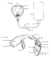
- the embodiment has a breathing mask 602 that includes a protective shield 603 for allowing the wearer thereof to have a clear field of vision.
- Mask 602 is in fluid communication with a breathing gas supply 604 via a breathing hose 608 and valve 610 .
- breathing gas supply 604 can be a SCBA breathing gas tank.
- pressure transmitter 102 is disposed in the breathing hose 608 , as shown. In other embodiments, pressure transmitter can be located proximate to or integral with valve 610 .
- mask 602 of the present invention has an oral-nasal breathing port 612 and one or more straps 614 for attaching the mask to the head of a wearer.
- receiver 104 is located within mask 602 .
- receiver 104 is preferably located within mask 602 so as to not interfere with the mask's breathing function through port 612 or its field of view characteristic through shield 603 .
- receiver 104 is preferably located so as to be in the field of view of a wearer of the mask without limiting the wearer's field of view outside through shield 603 .
- pressure transmitter 102 senses the pressure level in breathing gas supply 604 and transmits a radio frequency signal to the receiver 104 in mask 602 that is indicative of the amount of breathing gas in the breathing gas supply 604 .
- the receiver 102 being located in the mask 602 wearer's field of view, but not limiting the wearer's field of view outside the mask 602 , includes a display indicating the amount of breathing gas remaining in the breathing gas supply 604 and the battery status of the pressure transmitter.
- receiver 104 is shown removed from mask 602 .
- receiver 104 includes a battery portion 700 , display portion 702 and connecting portion 704 therebetween.
- Battery portion 700 includes a housing within which a battery for powering receiver 104 resides and a removable cover 701 used of accessing the battery and sealing the housing closed.
- Display portion 702 includes the previously discussed display 122 of FIG. 1 and can include a pressure display 706 and a battery status display 708 , each of which can include LEDs or other types of displays.
- Display portion 702 is also configured to, in some embodiments, house controller 120 , logic 121 , light sensor 124 , filter 126 and antenna 130 .
- pressure display 706 is illustrated as having four (4) LEDs 712 , 714 , 716 , and 718 that represent various levels of breathing gas in the breathing gas supply. More specifically, pressure information is conveyed by display 706 using a combination of LED color and position.
- the LEDs can be arranged in any orientation including horizontal (as shown), vertical, or any oblique angle and can include a variety of shapes or sizes depending on the space constraints. Additionally, discrete LEDs or a bank or array of LEDs can be employed.
- Other display 706 configurations include backlit Liquid Crystal Displays (LCDs) or incandescent lamps.
- LEDs 718 and 716 can be green in color when illuminated, while LED 714 can be yellow and LED 712 can be red.
- all four LEDs ( 718 , 716 , 714 , and 712 ) are illuminated.
- three LEDs ( 716 , 714 , and 712 ) are illuminated.
- two LEDs ( 714 and 712 ) are illuminated.
- one LED ( 712 ) is illuminated.
- LED 718 is illuminated green when the pressure transmitter 102 indicates that the amount of breathing gas remaining the breathing gas supply is greater than 3 ⁇ 4 of a tank.
- LED 716 is illuminated green when the pressure transmitter 102 indicates that the amount of breathing gas remaining the breathing gas supply is less than 3 ⁇ 4 but greater than 1 ⁇ 2 of a tank.
- LED 714 is illuminated yellow when the pressure transmitter 102 indicates that the amount of breathing gas remaining the breathing gas supply is less than 1 ⁇ 2 but greater than 1 ⁇ 4 of a tank.
- LED 712 is illuminated red when the pressure transmitter 102 indicates that the amount of breathing gas remaining the breathing gas supply is less than 1 ⁇ 2 but greater than 1 ⁇ 4 of a tank.
- Battery status 708 preferably includes receiver battery status LED 720 and transmitter battery status LED 722 .
- the receiver battery status LED 720 is preferably yellow and the transmitter battery status LED 722 green. Each LED is off when the battery status is good. Each LED blinks when its battery status falls below a predetermined minimum voltage.
- Receiver 104 is fitted with a mounting bracket 710 that provides for the attachment of receiver 104 within mask 602 , as shown in FIG. 6B .
- mounting bracket 710 has an arcuate shape configured to fit around the oral-nasal breathing port 612 . Configured as such, battery portion 700 resides to one side of the breathing port 612 and display portion 702 resides on the other side of breathing port 612 , thereby making effective use of the interior space of mask 602 .
- FIGS. 8A , 8 B, and 8 C Illustrated in FIGS. 8A , 8 B, and 8 C is one embodiment 800 of the pressure transmitter 102 of the present invention. More specifically, FIGS. 8A–8C illustrate various views of one embodiment of the pressure transmitter's housing 800 and pressure manifold 802 .
- Housing 800 preferably includes controller 106 , logic 108 , battery 110 , amplifier 114 , and antenna 116 .
- Manifold 802 preferably includes pressure sensor 112 . Housing 802 also includes a removable battery cover 804 that is removed when changing the transmitter's battery. So configured, housing 800 is affixed to manifold 802 .
- Manifold 802 has first and second orifices whereby the transmitter 102 is inserted inline with breathing gas hoses 608 .
- the pressure of the breathing gas in hose 608 is sensed in manifold 800 by pressure sensor 112 .
- Pressure sensor 112 outputs a pressure level signal to controller 106 in housing 800 for interpretation into a breathing gas level remaining in the breathing gas supply, which is transmitted via radio frequency to the receiver 104 in mask 602 .
- transmitter 800 can be located at the output of valve 610 or integral therewith.
- the data can be from any of several sensors including biometric, temperature, gas detection or others;
- the display can be any of several visual indicators including but not limited to LEDs, LCDs, incandescent lamps, or others; the information cab also be conveyed as an audible or spoken message through pre-recorded or speech synthesis means. Therefore, the invention, in its broader aspects, is not limited to the specific details, the representative apparatus, and illustrative examples shown and described. Accordingly, departures may be made from such details without departing from the spirit or scope of the applicant's general inventive concept.
Landscapes
- Health & Medical Sciences (AREA)
- Pulmonology (AREA)
- General Health & Medical Sciences (AREA)
- Business, Economics & Management (AREA)
- Emergency Management (AREA)
- Respiratory Apparatuses And Protective Means (AREA)
Abstract
Description
Claims (16)
Priority Applications (3)
| Application Number | Priority Date | Filing Date | Title |
|---|---|---|---|
| US10/224,527 US7089930B2 (en) | 2002-08-20 | 2002-08-20 | Wireless heads-up display for a self-contained breathing apparatus |
| AU2003259946A AU2003259946A1 (en) | 2002-08-20 | 2003-08-20 | Wireless heads-up display for a self-contained breathing apparatus |
| PCT/US2003/026063 WO2004018013A2 (en) | 2002-08-20 | 2003-08-20 | Wireless heads-up display for a self-contained breathing apparatus |
Applications Claiming Priority (1)
| Application Number | Priority Date | Filing Date | Title |
|---|---|---|---|
| US10/224,527 US7089930B2 (en) | 2002-08-20 | 2002-08-20 | Wireless heads-up display for a self-contained breathing apparatus |
Publications (2)
| Publication Number | Publication Date |
|---|---|
| US20040046710A1 US20040046710A1 (en) | 2004-03-11 |
| US7089930B2 true US7089930B2 (en) | 2006-08-15 |
Family
ID=31946277
Family Applications (1)
| Application Number | Title | Priority Date | Filing Date |
|---|---|---|---|
| US10/224,527 Expired - Lifetime US7089930B2 (en) | 2002-08-20 | 2002-08-20 | Wireless heads-up display for a self-contained breathing apparatus |
Country Status (3)
| Country | Link |
|---|---|
| US (1) | US7089930B2 (en) |
| AU (1) | AU2003259946A1 (en) |
| WO (1) | WO2004018013A2 (en) |
Cited By (38)
| Publication number | Priority date | Publication date | Assignee | Title |
|---|---|---|---|---|
| US20030025396A1 (en) * | 2001-08-06 | 2003-02-06 | Cheng-Lai Shen | Power supply system |
| US20030224838A1 (en) * | 2001-07-18 | 2003-12-04 | Greg Skillicorn | Mask communication system |
| US20050063561A1 (en) * | 2003-09-22 | 2005-03-24 | Joseph Birli | Dual microphone assembly for mask |
| US20050201548A1 (en) * | 2004-03-12 | 2005-09-15 | Joseph Birli | Telephone interface for mask |
| US20060050917A1 (en) * | 2004-09-03 | 2006-03-09 | Greg Skillicorn | Lapel microphone with push to talk switch |
| US20060125630A1 (en) * | 2002-12-23 | 2006-06-15 | Scott Technologies, Inc. | Dual-mesh network and communication system for emergency services personnel |
| US20060177084A1 (en) * | 2004-07-29 | 2006-08-10 | Greg Skillicorn | Mask amplifier with separated elements |
| US20060180153A1 (en) * | 2005-01-27 | 2006-08-17 | Bernie Schaub | Assembly for mounting a device to a mask |
| US20070221636A1 (en) * | 2006-03-23 | 2007-09-27 | Monzyk Doug J | Welding flash protection apparatus |
| US20080007396A1 (en) * | 2006-07-10 | 2008-01-10 | Scott Technologies, Inc. | Graphical user interface for emergency apparatus and method for operating same |
| US20080035145A1 (en) * | 2006-02-10 | 2008-02-14 | Adams Jonathan D | Communication system for heads-up display |
| US20080105262A1 (en) * | 2006-11-03 | 2008-05-08 | Victoria Stan Harold | Air filtering soft face mask |
| US20080105260A1 (en) * | 2006-11-02 | 2008-05-08 | Drager Medical Ag & Co. Kg | Method for determining the consumption of a co2 absorber in a respirator with rebreathing system |
| US7377835B2 (en) | 2002-12-23 | 2008-05-27 | Sti Licensing Corp. | Personal multimedia communication system and network for emergency services personnel |
| US7394905B2 (en) | 2004-03-26 | 2008-07-01 | Ultra Electronics Audiopack, Inc. | Voice amplifier for mask |
| US20090052714A1 (en) * | 2007-08-21 | 2009-02-26 | Ultra Electronics Audiopack, Inc. | High noise immunity emergency resonder communication system |
| US7571726B2 (en) * | 2004-03-22 | 2009-08-11 | Clipper Data Limited | Self-contained breathing apparatus |
| US20090241952A1 (en) * | 2008-03-31 | 2009-10-01 | Nellcor Puritan Bennett Llc | Systems and methods for compensating for pressure drop in a breathing assistance system |
| US7637164B1 (en) * | 2007-03-02 | 2009-12-29 | Reilly Kevin J | Apparatus for comparative pressure measurements of self-contained breathing apparatuses |
| US20100078025A1 (en) * | 2008-09-30 | 2010-04-01 | Grilliot William L | Breathing Apparatus with Sensor |
| US20100078023A1 (en) * | 2008-09-26 | 2010-04-01 | Nellcor Puritan Bennett Llc | Systems and methods for managing pressure in a breathing assistance system |
| US20100192094A1 (en) * | 2003-06-20 | 2010-07-29 | Resmed Limited | Flow generator with patient reminder |
| US8302602B2 (en) | 2008-09-30 | 2012-11-06 | Nellcor Puritan Bennett Llc | Breathing assistance system with multiple pressure sensors |
| US20130113620A1 (en) * | 2011-11-09 | 2013-05-09 | Draeger Safety Uk Limited | Monitoring apparatus |
| US20140014098A1 (en) * | 2012-07-11 | 2014-01-16 | Be Aerospace, Inc. | Aircraft crew member protective breathing apparatus |
| US8776790B2 (en) | 2009-07-16 | 2014-07-15 | Covidien Lp | Wireless, gas flow-powered sensor system for a breathing assistance system |
| US8789525B2 (en) | 2007-06-07 | 2014-07-29 | Resmed Limited | Tub for humidifier |
| US9027552B2 (en) | 2012-07-31 | 2015-05-12 | Covidien Lp | Ventilator-initiated prompt or setting regarding detection of asynchrony during ventilation |
| US9038631B2 (en) | 2003-06-20 | 2015-05-26 | Resmed Limited | Breathable gas apparatus with humidifier |
| DE102014204158A1 (en) | 2014-03-06 | 2015-09-10 | Msa Europe Gmbh | Mobile monitor |
| US9272116B2 (en) | 1999-08-05 | 2016-03-01 | Resmed R&D Germany Gmbh | Apparatus for humidifying a respiratory gas |
| US9604565B2 (en) | 2012-09-07 | 2017-03-28 | Ford Global Technologies, Llc | Wirelessly controlled heads-up display having solar charging and charge level indication |
| US9851752B2 (en) | 2013-02-13 | 2017-12-26 | Johnson Outdoors Inc. | Modular dive computer |
| US9950129B2 (en) | 2014-10-27 | 2018-04-24 | Covidien Lp | Ventilation triggering using change-point detection |
| US9993604B2 (en) | 2012-04-27 | 2018-06-12 | Covidien Lp | Methods and systems for an optimized proportional assist ventilation |
| US10362967B2 (en) | 2012-07-09 | 2019-07-30 | Covidien Lp | Systems and methods for missed breath detection and indication |
| US10676168B1 (en) * | 2019-04-30 | 2020-06-09 | United States Of America As Represented By The Secretary Of The Navy | Breathing-air tank pressure tracking system |
| US11324954B2 (en) | 2019-06-28 | 2022-05-10 | Covidien Lp | Achieving smooth breathing by modified bilateral phrenic nerve pacing |
Families Citing this family (18)
| Publication number | Priority date | Publication date | Assignee | Title |
|---|---|---|---|---|
| US8174436B2 (en) | 2002-07-08 | 2012-05-08 | American Underwater Products, Inc. | Dive computer with global positioning system receiver |
| US9443039B2 (en) | 2002-07-08 | 2016-09-13 | Pelagic Pressure Systems Corp. | Systems and methods for dive computers with remote upload capabilities |
| US8091422B2 (en) * | 2007-06-27 | 2012-01-10 | Avair, Llc | Breathing gas supply visual broadcast apparatus |
| US8122763B2 (en) * | 2006-09-01 | 2012-02-28 | Avair, Llc | Breathing gas supply visual broadcast apparatus |
| US7797124B2 (en) | 2006-12-28 | 2010-09-14 | American Underwater Products, Inc. | Dive computer with free dive mode and wireless data transmission |
| GB0701863D0 (en) * | 2007-01-31 | 2007-03-14 | Draeger Safety Uk Ltd | Improved head-up display unit |
| EP2137722A4 (en) | 2007-03-30 | 2014-06-25 | Savox Comm Oy Ab Ltd | A radio communication device |
| WO2009051896A2 (en) | 2007-08-31 | 2009-04-23 | 3M Innovative Properties Company | Determining conditions of personal protection articles against at least one criterion |
| WO2009048569A1 (en) * | 2007-10-08 | 2009-04-16 | Ronald Fundak | Optical display apparatus for breathing gas reserve in a tank |
| BR112012023657A2 (en) | 2010-07-02 | 2019-09-24 | Mine Safety Appliances Co | '' Breathing system, pressure regulator for use with a facepiece, method for providing information to a respirator user and breathing facepiece '' |
| CN102044130B (en) * | 2010-08-19 | 2012-07-04 | 上海宝亚安全装备有限公司 | Display alarm device |
| US9908599B2 (en) * | 2013-05-24 | 2018-03-06 | Shearwater Research Inc. | Heads-up display for displaying a partial pressure of oxygen to a diver |
| CN103949019A (en) * | 2014-04-29 | 2014-07-30 | 抚顺抚运安仪救生装备有限公司 | Air respirator with pressure head-up system |
| US9821893B2 (en) | 2014-10-06 | 2017-11-21 | Pelagic Pressure Systems Corp. | System and methods for configurable dive masks with multiple interfaces |
| CN104524710A (en) * | 2014-12-19 | 2015-04-22 | 南京耀泽电子科技有限公司 | Split type pressure head-up display device |
| US10274390B2 (en) | 2017-01-12 | 2019-04-30 | Johnson Outdoors Inc. | Tank pressure transmitter with integrated breathing gas analyzer |
| US10921597B2 (en) | 2018-08-22 | 2021-02-16 | Shearwater Research Inc. | Heads-up display for use in underwater applications |
| WO2022119684A1 (en) * | 2020-12-03 | 2022-06-09 | Xupermask Opco, Llc | Smart masks |
Citations (11)
| Publication number | Priority date | Publication date | Assignee | Title |
|---|---|---|---|---|
| US4949072A (en) * | 1987-03-03 | 1990-08-14 | Ernest Comerford | Dive parameter indicating assembly |
| US5033818A (en) * | 1989-01-13 | 1991-07-23 | Barr Howard S | Electronic diving system and face mask display |
| US5097826A (en) * | 1989-11-13 | 1992-03-24 | Cairns & Brother, Inc. | Pressure monitoring device for self-contained breathing apparatus |
| GB2283333A (en) * | 1993-10-29 | 1995-05-03 | John Charles Irvine | Divers mask having a display |
| US5570688A (en) * | 1993-11-17 | 1996-11-05 | Cochran Consulting, Inc. | Advanced dive computer for use with a self-contained underwater breathing apparatus |
| US5860418A (en) * | 1994-07-28 | 1999-01-19 | Comasec International S.A. | Method and an arrangement for checking the operation of breathing equipment |
| US6032644A (en) * | 1997-09-24 | 2000-03-07 | Robert Bosch Gmbh | Method and arrangement for controlling an internal combustion engine |
| US6095142A (en) * | 1998-06-25 | 2000-08-01 | Scott Technologies, Inc. | Progressive pressure indicator |
| US6310552B1 (en) * | 1991-08-06 | 2001-10-30 | North-South Corporation | Integrated firefighter safety monitoring and alarm system |
| US6334440B1 (en) * | 1993-11-17 | 2002-01-01 | Michael J. Cochran | Advanced dive computer that calculates and displays the users breathing parameter and water salinity |
| WO2002002191A1 (en) | 2000-06-30 | 2002-01-10 | Kuutti Tom L | Digital situation indicator |
-
2002
- 2002-08-20 US US10/224,527 patent/US7089930B2/en not_active Expired - Lifetime
-
2003
- 2003-08-20 WO PCT/US2003/026063 patent/WO2004018013A2/en not_active Application Discontinuation
- 2003-08-20 AU AU2003259946A patent/AU2003259946A1/en not_active Abandoned
Patent Citations (11)
| Publication number | Priority date | Publication date | Assignee | Title |
|---|---|---|---|---|
| US4949072A (en) * | 1987-03-03 | 1990-08-14 | Ernest Comerford | Dive parameter indicating assembly |
| US5033818A (en) * | 1989-01-13 | 1991-07-23 | Barr Howard S | Electronic diving system and face mask display |
| US5097826A (en) * | 1989-11-13 | 1992-03-24 | Cairns & Brother, Inc. | Pressure monitoring device for self-contained breathing apparatus |
| US6310552B1 (en) * | 1991-08-06 | 2001-10-30 | North-South Corporation | Integrated firefighter safety monitoring and alarm system |
| GB2283333A (en) * | 1993-10-29 | 1995-05-03 | John Charles Irvine | Divers mask having a display |
| US5570688A (en) * | 1993-11-17 | 1996-11-05 | Cochran Consulting, Inc. | Advanced dive computer for use with a self-contained underwater breathing apparatus |
| US6334440B1 (en) * | 1993-11-17 | 2002-01-01 | Michael J. Cochran | Advanced dive computer that calculates and displays the users breathing parameter and water salinity |
| US5860418A (en) * | 1994-07-28 | 1999-01-19 | Comasec International S.A. | Method and an arrangement for checking the operation of breathing equipment |
| US6032644A (en) * | 1997-09-24 | 2000-03-07 | Robert Bosch Gmbh | Method and arrangement for controlling an internal combustion engine |
| US6095142A (en) * | 1998-06-25 | 2000-08-01 | Scott Technologies, Inc. | Progressive pressure indicator |
| WO2002002191A1 (en) | 2000-06-30 | 2002-01-10 | Kuutti Tom L | Digital situation indicator |
Cited By (86)
| Publication number | Priority date | Publication date | Assignee | Title |
|---|---|---|---|---|
| US9302067B2 (en) | 1999-08-05 | 2016-04-05 | Resmed R&D Germany Gmbh | Apparatus for humidifying a respiratory gas |
| US9884163B2 (en) | 1999-08-05 | 2018-02-06 | RedMed R&D Germany GmbH | Apparatus for humidifying a respiratory gas |
| US9272116B2 (en) | 1999-08-05 | 2016-03-01 | Resmed R&D Germany Gmbh | Apparatus for humidifying a respiratory gas |
| US10052450B2 (en) | 1999-08-05 | 2018-08-21 | Resmed R&D Germany Gmbh | Apparatus for humidifying a respiratory gas |
| US9545493B2 (en) | 1999-08-05 | 2017-01-17 | Resmed R&D Germany Gmbh | Apparatus for humidifying a respiratory gas |
| US9555211B2 (en) | 1999-08-05 | 2017-01-31 | Resmed R&D Germany Gmbh | Apparatus for humidifying a respiratory gas |
| US9545494B2 (en) | 1999-08-05 | 2017-01-17 | Resmed R&D Germany Gmbh | Apparatus for humidifying a respiratory gas |
| US20030224838A1 (en) * | 2001-07-18 | 2003-12-04 | Greg Skillicorn | Mask communication system |
| US20030025396A1 (en) * | 2001-08-06 | 2003-02-06 | Cheng-Lai Shen | Power supply system |
| US8755839B2 (en) | 2002-12-23 | 2014-06-17 | Sti Licensing Corp. | Personal multimedia communication system and network for emergency services personnel |
| US7398097B2 (en) * | 2002-12-23 | 2008-07-08 | Scott Technologies, Inc. | Dual-mesh network and communication system for emergency services personnel |
| US20060125630A1 (en) * | 2002-12-23 | 2006-06-15 | Scott Technologies, Inc. | Dual-mesh network and communication system for emergency services personnel |
| US9257028B2 (en) | 2002-12-23 | 2016-02-09 | Scott Technologies, Inc. | Dual-network locator and communication system for emergency services personnel |
| US20080284589A1 (en) * | 2002-12-23 | 2008-11-20 | Scott Technologies, Inc. | Dual-network locator and communication system for emergency services personnel |
| US7377835B2 (en) | 2002-12-23 | 2008-05-27 | Sti Licensing Corp. | Personal multimedia communication system and network for emergency services personnel |
| USRE46543E1 (en) | 2003-06-20 | 2017-09-12 | Resmed Limited | Breathable gas apparatus with humidifier |
| US10293125B2 (en) * | 2003-06-20 | 2019-05-21 | Resmed Limited | Flow generator with patient reminder |
| US9227035B2 (en) | 2003-06-20 | 2016-01-05 | Resmed Limited | Breathable gas apparatus with humidifier |
| US9358359B2 (en) | 2003-06-20 | 2016-06-07 | Resmed Limited | Breathable gas apparatus with humidifier |
| US11413412B2 (en) | 2003-06-20 | 2022-08-16 | ResMed Pty Ltd | Breathable gas supply apparatus |
| US9539409B2 (en) | 2003-06-20 | 2017-01-10 | Resmed Limited | Breathable gas apparatus with humidifier |
| US11260187B2 (en) | 2003-06-20 | 2022-03-01 | ResMed Pty Ltd | Breathable gas supply apparatus |
| US9072860B2 (en) | 2003-06-20 | 2015-07-07 | Resmed Limited | Breathable gas apparatus with humidifier |
| US9038632B2 (en) | 2003-06-20 | 2015-05-26 | Resmed Limited | Breathable gas apparatus with humidifier |
| US11235115B2 (en) | 2003-06-20 | 2022-02-01 | ResMed Pty Ltd | Breathable gas apparatus with humidifier |
| US10881820B2 (en) | 2003-06-20 | 2021-01-05 | ResMed Pty Ltd | Breathable gas apparatus with humidifier |
| US20100192094A1 (en) * | 2003-06-20 | 2010-07-29 | Resmed Limited | Flow generator with patient reminder |
| US9038631B2 (en) | 2003-06-20 | 2015-05-26 | Resmed Limited | Breathable gas apparatus with humidifier |
| US9610420B2 (en) | 2003-06-20 | 2017-04-04 | Resmed Limited | Breathable gas apparatus with humidifier |
| US10201676B2 (en) | 2003-06-20 | 2019-02-12 | Resmed Limited | Breathable gas supply apparatus |
| US10850053B2 (en) | 2003-06-20 | 2020-12-01 | ResMed Pty Ltd | Breathable gas supply apparatus |
| US20050063561A1 (en) * | 2003-09-22 | 2005-03-24 | Joseph Birli | Dual microphone assembly for mask |
| US7457427B2 (en) | 2003-09-22 | 2008-11-25 | Ultra Electronics Audiopack, Inc. | Dual microphone assembly for mask |
| US20050201548A1 (en) * | 2004-03-12 | 2005-09-15 | Joseph Birli | Telephone interface for mask |
| US7571726B2 (en) * | 2004-03-22 | 2009-08-11 | Clipper Data Limited | Self-contained breathing apparatus |
| US7394905B2 (en) | 2004-03-26 | 2008-07-01 | Ultra Electronics Audiopack, Inc. | Voice amplifier for mask |
| US20060177084A1 (en) * | 2004-07-29 | 2006-08-10 | Greg Skillicorn | Mask amplifier with separated elements |
| US20060050917A1 (en) * | 2004-09-03 | 2006-03-09 | Greg Skillicorn | Lapel microphone with push to talk switch |
| US7349551B2 (en) | 2004-09-03 | 2008-03-25 | Ultra Electronics Audiopack, Inc. | Lapel microphone with push to talk switch |
| US20060180153A1 (en) * | 2005-01-27 | 2006-08-17 | Bernie Schaub | Assembly for mounting a device to a mask |
| US20100308991A1 (en) * | 2006-02-10 | 2010-12-09 | Undersea Sensor Systems. Inc. | Communication system for heads-up display |
| US20080035145A1 (en) * | 2006-02-10 | 2008-02-14 | Adams Jonathan D | Communication system for heads-up display |
| US7812279B2 (en) * | 2006-03-23 | 2010-10-12 | Monzyk Doug J | Welding flash protection apparatus |
| US20070221636A1 (en) * | 2006-03-23 | 2007-09-27 | Monzyk Doug J | Welding flash protection apparatus |
| US20080007396A1 (en) * | 2006-07-10 | 2008-01-10 | Scott Technologies, Inc. | Graphical user interface for emergency apparatus and method for operating same |
| US7652571B2 (en) | 2006-07-10 | 2010-01-26 | Scott Technologies, Inc. | Graphical user interface for emergency apparatus and method for operating same |
| US8599016B2 (en) | 2006-07-10 | 2013-12-03 | Scott Technologies, Inc. | Graphical user interface for emergency apparatus and method for operating same |
| US8013739B2 (en) | 2006-07-10 | 2011-09-06 | Scott Technologies, Inc. | Graphical user interface for emergency apparatus and method for operating same |
| US20080105260A1 (en) * | 2006-11-02 | 2008-05-08 | Drager Medical Ag & Co. Kg | Method for determining the consumption of a co2 absorber in a respirator with rebreathing system |
| US7987849B2 (en) * | 2006-11-02 | 2011-08-02 | Dräger Medical GmbH | Method for determining the consumption of a CO2 absorber in a respirator with rebreathing system |
| US20080105262A1 (en) * | 2006-11-03 | 2008-05-08 | Victoria Stan Harold | Air filtering soft face mask |
| US7637164B1 (en) * | 2007-03-02 | 2009-12-29 | Reilly Kevin J | Apparatus for comparative pressure measurements of self-contained breathing apparatuses |
| US8789525B2 (en) | 2007-06-07 | 2014-07-29 | Resmed Limited | Tub for humidifier |
| US10478585B2 (en) | 2007-06-07 | 2019-11-19 | ResMed Pty Ltd | Tub for humidifier |
| US20090052714A1 (en) * | 2007-08-21 | 2009-02-26 | Ultra Electronics Audiopack, Inc. | High noise immunity emergency resonder communication system |
| US20090241952A1 (en) * | 2008-03-31 | 2009-10-01 | Nellcor Puritan Bennett Llc | Systems and methods for compensating for pressure drop in a breathing assistance system |
| US8353291B2 (en) | 2008-03-31 | 2013-01-15 | Covidien Lp | Systems and methods for compensating for pressure drop in a breathing assistance system |
| US8720442B2 (en) | 2008-09-26 | 2014-05-13 | Covidien Lp | Systems and methods for managing pressure in a breathing assistance system |
| US8181648B2 (en) | 2008-09-26 | 2012-05-22 | Nellcor Puritan Bennett Llc | Systems and methods for managing pressure in a breathing assistance system |
| US20100078023A1 (en) * | 2008-09-26 | 2010-04-01 | Nellcor Puritan Bennett Llc | Systems and methods for managing pressure in a breathing assistance system |
| US20100078025A1 (en) * | 2008-09-30 | 2010-04-01 | Grilliot William L | Breathing Apparatus with Sensor |
| US9649458B2 (en) | 2008-09-30 | 2017-05-16 | Covidien Lp | Breathing assistance system with multiple pressure sensors |
| US8302602B2 (en) | 2008-09-30 | 2012-11-06 | Nellcor Puritan Bennett Llc | Breathing assistance system with multiple pressure sensors |
| US8316850B2 (en) * | 2008-09-30 | 2012-11-27 | Honeywell International Inc. | Breathing apparatus with sensor |
| US8776790B2 (en) | 2009-07-16 | 2014-07-15 | Covidien Lp | Wireless, gas flow-powered sensor system for a breathing assistance system |
| US9390609B2 (en) * | 2011-11-09 | 2016-07-12 | Draeger Safety Uk Limited | Monitoring apparatus |
| US20130113620A1 (en) * | 2011-11-09 | 2013-05-09 | Draeger Safety Uk Limited | Monitoring apparatus |
| US9993604B2 (en) | 2012-04-27 | 2018-06-12 | Covidien Lp | Methods and systems for an optimized proportional assist ventilation |
| US10806879B2 (en) | 2012-04-27 | 2020-10-20 | Covidien Lp | Methods and systems for an optimized proportional assist ventilation |
| US10362967B2 (en) | 2012-07-09 | 2019-07-30 | Covidien Lp | Systems and methods for missed breath detection and indication |
| US11642042B2 (en) | 2012-07-09 | 2023-05-09 | Covidien Lp | Systems and methods for missed breath detection and indication |
| US10046184B2 (en) | 2012-07-11 | 2018-08-14 | B/E Aerospace, Inc. | Aircraft crew member protective breathing apparatus |
| US9498656B2 (en) * | 2012-07-11 | 2016-11-22 | B/E Aerospace, Inc. | Aircraft crew member protective breathing apparatus |
| US20140014098A1 (en) * | 2012-07-11 | 2014-01-16 | Be Aerospace, Inc. | Aircraft crew member protective breathing apparatus |
| US9027552B2 (en) | 2012-07-31 | 2015-05-12 | Covidien Lp | Ventilator-initiated prompt or setting regarding detection of asynchrony during ventilation |
| US9604565B2 (en) | 2012-09-07 | 2017-03-28 | Ford Global Technologies, Llc | Wirelessly controlled heads-up display having solar charging and charge level indication |
| US9851752B2 (en) | 2013-02-13 | 2017-12-26 | Johnson Outdoors Inc. | Modular dive computer |
| DE102014204158A1 (en) | 2014-03-06 | 2015-09-10 | Msa Europe Gmbh | Mobile monitor |
| US10395501B2 (en) | 2014-03-06 | 2019-08-27 | Msa Europe Gmbh | Mobile monitoring device |
| DE102014204158B4 (en) | 2014-03-06 | 2018-12-13 | Msa Europe Gmbh | Mobile monitor |
| WO2015132393A1 (en) | 2014-03-06 | 2015-09-11 | Msa Europe Gmbh | Mobile monitoring device |
| US9950129B2 (en) | 2014-10-27 | 2018-04-24 | Covidien Lp | Ventilation triggering using change-point detection |
| US10940281B2 (en) | 2014-10-27 | 2021-03-09 | Covidien Lp | Ventilation triggering |
| US11712174B2 (en) | 2014-10-27 | 2023-08-01 | Covidien Lp | Ventilation triggering |
| US10676168B1 (en) * | 2019-04-30 | 2020-06-09 | United States Of America As Represented By The Secretary Of The Navy | Breathing-air tank pressure tracking system |
| US11324954B2 (en) | 2019-06-28 | 2022-05-10 | Covidien Lp | Achieving smooth breathing by modified bilateral phrenic nerve pacing |
Also Published As
| Publication number | Publication date |
|---|---|
| WO2004018013A2 (en) | 2004-03-04 |
| US20040046710A1 (en) | 2004-03-11 |
| WO2004018013A3 (en) | 2004-08-26 |
| AU2003259946A8 (en) | 2004-03-11 |
| AU2003259946A1 (en) | 2004-03-11 |
Similar Documents
| Publication | Publication Date | Title |
|---|---|---|
| US7089930B2 (en) | Wireless heads-up display for a self-contained breathing apparatus | |
| US8122763B2 (en) | Breathing gas supply visual broadcast apparatus | |
| WO2007095266A2 (en) | Communication system for heads-up display | |
| US8091422B2 (en) | Breathing gas supply visual broadcast apparatus | |
| US10441828B2 (en) | Powered air-purifying respirator | |
| US6334440B1 (en) | Advanced dive computer that calculates and displays the users breathing parameter and water salinity | |
| AU2016206435B2 (en) | Filter assembly for a breathing apparatus | |
| US20070215157A1 (en) | Rebreather Setpoint Controller and Display | |
| US5146209A (en) | Self-contained apparatus for emergency lighting incorporating alarm systems for fire, gas and the like | |
| US7571726B2 (en) | Self-contained breathing apparatus | |
| US6091331A (en) | Emergency worker and fireman's dual emergency warning system | |
| US8082922B2 (en) | Head-up display unit | |
| IL170062A (en) | Adaptive tourniquet cuff system | |
| US20050263155A1 (en) | Pressure indicator for positive pressure protection masks | |
| WO2015036652A1 (en) | Power supply of a welding helmet | |
| KR101864250B1 (en) | Optical fiber luminescent patch type wearable device which can be used in a dangerous environment of gas leakage and its control method | |
| KR20050061938A (en) | Fire detection system by radio frequency communication and power line communication | |
| WO2009048569A1 (en) | Optical display apparatus for breathing gas reserve in a tank | |
| EP3074094B1 (en) | Breathing apparatus with illuminated connection | |
| CN210428461U (en) | Medical wrist strap and ward inspection system | |
| CN206103136U (en) | Atmospheric pressure alarm system and respirator equipment | |
| WO2002004058A8 (en) | Monitoring and control for a laryngeal mask airway device | |
| CN215726105U (en) | Remote ammeter supervisory equipment | |
| AU644845B2 (en) | Self-contained apparatus for emergency lighting incorporating alarm systems for fire, gas and the like | |
| CN211505407U (en) | Calibration gas station for calibrating gas sensors in explosive environments |
Legal Events
| Date | Code | Title | Description |
|---|---|---|---|
| AS | Assignment |
Owner name: AUDIOPACK TECHNOLOGIES, INC., OHIO Free format text: ASSIGNMENT OF ASSIGNORS INTEREST;ASSIGNORS:ADAMS, JONATHAN D.;BIRLI, JOSEPH;SKILLICORN, GREG;AND OTHERS;REEL/FRAME:013492/0882;SIGNING DATES FROM 20021024 TO 20021031 |
|
| STCF | Information on status: patent grant |
Free format text: PATENTED CASE |
|
| AS | Assignment |
Owner name: ULTRA ELECTRONICS AUDIOPACK, INC., OHIO Free format text: CHANGE OF NAME;ASSIGNOR:AUDIOPACK TECHNOLOGIES, INC.;REEL/FRAME:019287/0420 Effective date: 20050729 |
|
| AS | Assignment |
Owner name: ULTRA ELECTRONICS AUDIOPACK, INC., OHIO Free format text: ASSIGNMENT OF ASSIGNORS INTEREST;ASSIGNOR:AUDIOPACK TECHNOLOGIES, INC.;REEL/FRAME:019690/0363 Effective date: 20050715 |
|
| AS | Assignment |
Owner name: UNDERSEA SENSOR SYSTEMS, INC., INDIANA Free format text: ASSIGNMENT OF ASSIGNORS INTEREST;ASSIGNOR:ULTRA ELECTRONICS AUDIOPACK, INC.;REEL/FRAME:021976/0449 Effective date: 20081203 |
|
| FPAY | Fee payment |
Year of fee payment: 4 |
|
| REMI | Maintenance fee reminder mailed | ||
| FPAY | Fee payment |
Year of fee payment: 8 |
|
| SULP | Surcharge for late payment |
Year of fee payment: 7 |
|
| FEPP | Fee payment procedure |
Free format text: PAYOR NUMBER ASSIGNED (ORIGINAL EVENT CODE: ASPN); ENTITY STATUS OF PATENT OWNER: LARGE ENTITY |
|
| MAFP | Maintenance fee payment |
Free format text: PAYMENT OF MAINTENANCE FEE, 12TH YEAR, LARGE ENTITY (ORIGINAL EVENT CODE: M1553) Year of fee payment: 12 |