US7077370B2 - Hair dryer stand for a handheld hair dryer - Google Patents
Hair dryer stand for a handheld hair dryer Download PDFInfo
- Publication number
- US7077370B2 US7077370B2 US10/819,988 US81998804A US7077370B2 US 7077370 B2 US7077370 B2 US 7077370B2 US 81998804 A US81998804 A US 81998804A US 7077370 B2 US7077370 B2 US 7077370B2
- Authority
- US
- United States
- Prior art keywords
- hair dryer
- dryer stand
- sides
- fasteners
- base
- Prior art date
- Legal status (The legal status is an assumption and is not a legal conclusion. Google has not performed a legal analysis and makes no representation as to the accuracy of the status listed.)
- Expired - Fee Related, expires
Links
Images


Classifications
-
- A—HUMAN NECESSITIES
- A45—HAND OR TRAVELLING ARTICLES
- A45D—HAIRDRESSING OR SHAVING EQUIPMENT; EQUIPMENT FOR COSMETICS OR COSMETIC TREATMENTS, e.g. FOR MANICURING OR PEDICURING
- A45D20/00—Hair drying devices; Accessories therefor
- A45D20/04—Hot-air producers
- A45D20/08—Hot-air producers heated electrically
- A45D20/10—Hand-held drying devices, e.g. air douches
- A45D20/12—Details thereof or accessories therefor, e.g. nozzles, stands
- A45D2020/126—Stands therefor
Definitions
- the present invention relates to a hair dryer stand, and more particularly to a hair dryer stand for a handheld hair dryer, which is able to hold a hair dryer when the hair dryer is being used.
- Hair dryers are very common household appliances. Particularly, women who like to make themselves prettier consider hair dryers a necessity.
- the person When a person uses a hair dryer, the person needs one hand to hold the hair dryer and another hand to hold a tool, such as a hairbrush, hair spray, etc.
- the hair dryer is useful, the need to hold the hair dryer is a significant limitation. When a person needs both hands to style their hair or do other things like writing or holding another tool, the hair dryer can only be used intermittently, or the person needs an extra hand.
- the present invention provides a hair dryer stand to mitigate or obviate the aforementioned problems.
- the primary objective of the present invention is to provide a hair dryer stand for a handheld hair dryer that will allow a person to use the hair dryer without holding the hair dryer.
- Another objective of the present invention is to provide a holder that is pivotal relative to the base such that the angle of the hair dryer can be adjusted to different positions.
- FIG. 1 is an exploded perspective view of the hair dryer stand in accordance with the present invention
- FIG. 2 is an exploded bottom perspective view of the hair dryer stand in FIG. 1 ;
- FIG. 3 is a perspective view of the hair dryer stand in FIG. 1 ;
- FIG. 4 is an operational perspective view of the hair dryer in FIG. 3 with a hair dryer
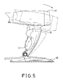
- FIG. 5 is an operational side plan view of the hair dryer stand and hair dryer in FIG. 4 adjusted relative to the base;
- FIG. 6 is another operational side plan view of the hair dryer stand and hair dryer in FIG. 4 securely attached to a vertical surface.
- a hair dryer stand for a handheld hair dryer with a handle comprises a base ( 10 ) and a holder ( 20 ).
- the holder ( 20 ) is mounted pivotally on the base ( 10 ) and has two curved sides ( 21 , 22 ) and a space ( 23 ).
- the curved sides ( 21 , 22 ) are formed with each another and define the space ( 23 ) between the curved sides ( 21 , 22 ).
- Each curved side ( 21 , 22 ) has a mediate section (not numbered), a proximal end (not numbered), a distal end (not numbered), an outside surface (not numbered), an inside surface (not numbered), an optional cutout ( 211 , 221 ) and a pivot pin ( 212 , 222 ).
- the cutouts ( 211 , 221 ) are defined respectively in the mediate sections of the curved sides ( 21 , 22 ) to facilitate access to the hair dryer.
- the pivot pins ( 212 , 222 ) are formed respectively on the outside surfaces of the curved side ( 21 , 22 ) near the proximal end and are aligned with each other.
- Each pivot pin ( 212 , 222 ) has an axial threaded hole ( 213 , 223 ) defined longitudinally through the pivot pin ( 212 , 222 ).
- the base ( 10 ) has two sides (not numbered), a top face (not numbered), a bottom face (not numbered), a first ear ( 11 ), a second ear ( 12 ), an optional mounting recess ( 13 ) and an optional wall bracket ( 14 ).
- the first and second ears ( 11 , 12 ) are formed on and extend up from the top face of the base ( 10 ) respectively near the sides, are aligned with each other and respectively have inside surfaces (not numbered), outside surfaces (not numbered), recessed areas ( 111 , 121 ), pivot holes ( 112 , 122 ), fastener assemblies (not numbered) and optional caps ( 113 , 123 ).
- the recessed area ( 111 , 121 ) are defined respectively in the outside surfaces of the first and second ears ( 11 , 12 ), are aligned with each other and respectively have centers (not numbered) and bottoms (not numbered).
- the pivot holes ( 112 , 122 ) are defined respectively through the centers of the recessed areas ( 111 , 121 ).
- the fastener assemblies pivotally connect the holder ( 20 ) to the ears ( 11 , 12 ) and respectively comprise two washers (not numbered), two lock washers (not numbered) and two fasteners (not numbered).
- the washers and lock washers are sequentially mounted respectively in the recessed areas ( 111 , 121 ) with the lock washers respectively in the bottoms of the recessed areas ( 111 , 112 ).
- the fasteners may be bolts ( 114 , 124 ) or screws (not shown), pass respectively through the washers, lock washers and pivot holes ( 112 , 122 ) and screw respectively into the threaded holes ( 213 , 223 ).
- the caps ( 113 , 123 ) are mounted respectively in and cover the recessed areas ( 111 , 121 ) in the ears ( 11 , 12 ).
- the mounting recess ( 13 ) is defined in the bottom face of the base ( 10 ) and has a top end (not numbered), a bottom end (not numbered), two sides (not numbered) and at least one lip (not numbered).
- the at least one lip is located at the top end of the mounting recess ( 13 ) and may be a single lip (not numbered) or two lips ( 131 , 132 ). Where a single lip is implemented, the lip is located at the top end of the mounting recess ( 13 ). Where two lips ( 131 , 132 ) are implemented, the two lips ( 131 , 132 ) are located respectively on opposite sides of the mounting recess ( 13 ) at the top end.
- the wall bracket ( 14 ) is connected to a vertical surface and has a top end (not numbered), two sides (not numbered), a front surface (not numbered) and a rear surface (not numbered) and at least one tongue (not numbered).
- the wall bracket ( 14 ) has a single tongue (not numbered) parallel to the front surface and protruding toward the top end, which selectively engages the lip in the mounting recess ( 13 ) corresponding to the at least one lip in the mounting recess ( 13 ).
- the wall bracket ( 14 ) has two tongues ( 141 , 142 ) parallel to the front surface and protruding respectively toward the sides, which selectively engage the lips ( 131 , 132 ) in the mounting recess ( 13 ).
- a handheld hair dryer ( 30 ) has a handle ( 31 ) that is firmly mounted and clamped in the space ( 23 ) in the holder ( 20 ) between the two curved sides ( 21 , 22 ).
- the holder ( 20 ) is adjusted to an angle relative to the base ( 10 ) to accommodate a specific user.
- the lock washers can provide a holding stress to the holder ( 20 ). Accordingly, the holder ( 20 ) can be held at any desired position with the holding stress provided by the lock washers.
- the wall bracket ( 14 ) can be attached to a wall ( 40 ) with screws (not shown), nails (not shown), double sided tape (not shown) or the like.
- the mounting recess ( 13 ) is mounted on the wall bracket ( 14 ) to hang the hair dryer ( 30 ) on the wall ( 40 ).
- the angle of the hair dryer ( 30 ) can be adjusted to dry a person's hair.
Abstract
Description
Claims (12)
Priority Applications (1)
| Application Number | Priority Date | Filing Date | Title |
|---|---|---|---|
| US10/819,988 US7077370B2 (en) | 2004-04-08 | 2004-04-08 | Hair dryer stand for a handheld hair dryer |
Applications Claiming Priority (1)
| Application Number | Priority Date | Filing Date | Title |
|---|---|---|---|
| US10/819,988 US7077370B2 (en) | 2004-04-08 | 2004-04-08 | Hair dryer stand for a handheld hair dryer |
Publications (2)
| Publication Number | Publication Date |
|---|---|
| US20050224666A1 US20050224666A1 (en) | 2005-10-13 |
| US7077370B2 true US7077370B2 (en) | 2006-07-18 |
Family
ID=35059599
Family Applications (1)
| Application Number | Title | Priority Date | Filing Date |
|---|---|---|---|
| US10/819,988 Expired - Fee Related US7077370B2 (en) | 2004-04-08 | 2004-04-08 | Hair dryer stand for a handheld hair dryer |
Country Status (1)
| Country | Link |
|---|---|
| US (1) | US7077370B2 (en) |
Cited By (12)
| Publication number | Priority date | Publication date | Assignee | Title |
|---|---|---|---|---|
| US20050279353A1 (en) * | 2004-06-07 | 2005-12-22 | Mccoy Mark S | Intra-convertible thermal vapor extraction and delivery system |
| US20070000851A1 (en) * | 2005-06-24 | 2007-01-04 | Matzick Rick E | Gun rack |
| US20070245590A1 (en) * | 2004-07-12 | 2007-10-25 | Lori Burk | Hair dryer stand |
| US20090065661A1 (en) * | 2004-07-12 | 2009-03-12 | Burk Lori H | Hair Dryer Stand |
| US20100014844A1 (en) * | 2008-07-17 | 2010-01-21 | Jeff Dannenberg | Manually adjustable hair dryer mount for use with a hand-held hair dryer |
| US20100012344A1 (en) * | 2008-07-17 | 2010-01-21 | Jeff Dannenberg | Hair dryer mount with oscillating holder for use with a hand-held hair dryer |
| USD791074S1 (en) * | 2016-04-19 | 2017-07-04 | Faraday & Future Inc. | Electric vehicle charging station |
| US20190104820A1 (en) * | 2017-10-06 | 2019-04-11 | Peggy A. Williams | Mc professional hairdryer with secure attachments |
| US20210321739A1 (en) * | 2019-04-12 | 2021-10-21 | Roman Viktorovich Kulikov | Mobile Holder for Hairdressing Tools and Accessories |
| WO2022015191A1 (en) | 2020-07-15 | 2022-01-20 | Елена Игоревна КАЗАНЦЕВА | Hairdryer holder |
| US11287084B1 (en) * | 2020-09-25 | 2022-03-29 | National Products, Inc. | Holder for scanner guns and other devices and methods of making and using |
| RU2805697C1 (en) * | 2020-07-15 | 2023-10-23 | Елена Игоревна Казанцева | Hair dryer holder |
Families Citing this family (3)
| Publication number | Priority date | Publication date | Assignee | Title |
|---|---|---|---|---|
| GB2560889B (en) | 2017-03-22 | 2020-09-23 | Dyson Technology Ltd | Support for a hair care appliance |
| GB2560888B (en) | 2017-03-22 | 2020-04-08 | Dyson Technology Ltd | Support for a hair care appliance |
| JP7098193B1 (en) * | 2021-02-22 | 2022-07-11 | 株式会社Kalos Beauty Technology | Hair dryer stand |
Citations (20)
| Publication number | Priority date | Publication date | Assignee | Title |
|---|---|---|---|---|
| US2421643A (en) * | 1944-07-08 | 1947-06-03 | Arnold J Ostli | Safety helmet |
| US2500048A (en) * | 1947-01-30 | 1950-03-07 | Eastman Kodak Co | Clamping device |
| US2778931A (en) * | 1953-04-03 | 1957-01-22 | Ruben A Cruz | Folding flashlight holder |
| US3008259A (en) * | 1960-02-12 | 1961-11-14 | William F Zornes | Fishing outrigger |
| US3322388A (en) * | 1965-10-11 | 1967-05-30 | Monarch Tool & Machinery Co | Hinged joint support for a rear vision mirror mounting |
| US3501119A (en) * | 1968-08-01 | 1970-03-17 | Troxel Mfg Co | Bicycle seat supporting pivot means |
| US4341452A (en) * | 1981-08-10 | 1982-07-27 | Torkel Korling | Triaxial universal camera mount |
| US4671476A (en) * | 1986-01-10 | 1987-06-09 | Euisub Yim | Adjustable soldering iron stand |
| US4874142A (en) * | 1988-11-25 | 1989-10-17 | Gelatt Sharon G | Blow dryer holder |
| US5069407A (en) * | 1990-11-02 | 1991-12-03 | Williams Andy C | Mounting bracket for communication related devices |
| US5172880A (en) * | 1991-01-29 | 1992-12-22 | China Pacific Trade Limited | Holder for a blow dryer or other appliance |
| US5392350A (en) * | 1992-05-18 | 1995-02-21 | Swanson; Paul J. | Support apparatus for a transportable telephone |
| US5590475A (en) * | 1995-04-25 | 1997-01-07 | Andis Company | Hand held appliance and holder assembly |
| US5636815A (en) * | 1995-08-16 | 1997-06-10 | Wilson; Dorina S. | Mounting fixture for a hand-held hair dryer |
| USD391266S (en) * | 1997-07-14 | 1998-02-24 | Herbert Richter | Dual hinge mounting bracket with telephone holder |
| US5937537A (en) * | 1998-09-18 | 1999-08-17 | Miller; Leticia | Combination hair dryer and stand |
| US6018847A (en) * | 1998-07-02 | 2000-02-01 | Lu; Sheng-Nan | Hinge axle device for a LCD monitor |
| US6390424B1 (en) * | 2000-07-13 | 2002-05-21 | Margo Kidushim | Accessory support device and method |
| US20020107043A1 (en) * | 2001-01-19 | 2002-08-08 | Adamson Alan D. | Cordless phone apparatus |
| US6520467B2 (en) * | 1999-06-16 | 2003-02-18 | Anne Marie Thomas | Hair dryer holder |
-
2004
- 2004-04-08 US US10/819,988 patent/US7077370B2/en not_active Expired - Fee Related
Patent Citations (20)
| Publication number | Priority date | Publication date | Assignee | Title |
|---|---|---|---|---|
| US2421643A (en) * | 1944-07-08 | 1947-06-03 | Arnold J Ostli | Safety helmet |
| US2500048A (en) * | 1947-01-30 | 1950-03-07 | Eastman Kodak Co | Clamping device |
| US2778931A (en) * | 1953-04-03 | 1957-01-22 | Ruben A Cruz | Folding flashlight holder |
| US3008259A (en) * | 1960-02-12 | 1961-11-14 | William F Zornes | Fishing outrigger |
| US3322388A (en) * | 1965-10-11 | 1967-05-30 | Monarch Tool & Machinery Co | Hinged joint support for a rear vision mirror mounting |
| US3501119A (en) * | 1968-08-01 | 1970-03-17 | Troxel Mfg Co | Bicycle seat supporting pivot means |
| US4341452A (en) * | 1981-08-10 | 1982-07-27 | Torkel Korling | Triaxial universal camera mount |
| US4671476A (en) * | 1986-01-10 | 1987-06-09 | Euisub Yim | Adjustable soldering iron stand |
| US4874142A (en) * | 1988-11-25 | 1989-10-17 | Gelatt Sharon G | Blow dryer holder |
| US5069407A (en) * | 1990-11-02 | 1991-12-03 | Williams Andy C | Mounting bracket for communication related devices |
| US5172880A (en) * | 1991-01-29 | 1992-12-22 | China Pacific Trade Limited | Holder for a blow dryer or other appliance |
| US5392350A (en) * | 1992-05-18 | 1995-02-21 | Swanson; Paul J. | Support apparatus for a transportable telephone |
| US5590475A (en) * | 1995-04-25 | 1997-01-07 | Andis Company | Hand held appliance and holder assembly |
| US5636815A (en) * | 1995-08-16 | 1997-06-10 | Wilson; Dorina S. | Mounting fixture for a hand-held hair dryer |
| USD391266S (en) * | 1997-07-14 | 1998-02-24 | Herbert Richter | Dual hinge mounting bracket with telephone holder |
| US6018847A (en) * | 1998-07-02 | 2000-02-01 | Lu; Sheng-Nan | Hinge axle device for a LCD monitor |
| US5937537A (en) * | 1998-09-18 | 1999-08-17 | Miller; Leticia | Combination hair dryer and stand |
| US6520467B2 (en) * | 1999-06-16 | 2003-02-18 | Anne Marie Thomas | Hair dryer holder |
| US6390424B1 (en) * | 2000-07-13 | 2002-05-21 | Margo Kidushim | Accessory support device and method |
| US20020107043A1 (en) * | 2001-01-19 | 2002-08-08 | Adamson Alan D. | Cordless phone apparatus |
Cited By (18)
| Publication number | Priority date | Publication date | Assignee | Title |
|---|---|---|---|---|
| US20050279353A1 (en) * | 2004-06-07 | 2005-12-22 | Mccoy Mark S | Intra-convertible thermal vapor extraction and delivery system |
| US7826726B2 (en) * | 2004-06-07 | 2010-11-02 | Mccoy Mark S | Intra-convertible thermal vapor extraction and delivery system |
| US7784750B2 (en) * | 2004-07-12 | 2010-08-31 | Lori Burk | Hair dryer stand |
| US8517318B2 (en) | 2004-07-12 | 2013-08-27 | Lori H Burk | Hair dryer stand |
| US20070245590A1 (en) * | 2004-07-12 | 2007-10-25 | Lori Burk | Hair dryer stand |
| US20090065661A1 (en) * | 2004-07-12 | 2009-03-12 | Burk Lori H | Hair Dryer Stand |
| US7559428B2 (en) * | 2005-06-24 | 2009-07-14 | Rick Edwin Matzick | Gun rack |
| US20070000851A1 (en) * | 2005-06-24 | 2007-01-04 | Matzick Rick E | Gun rack |
| US20100012344A1 (en) * | 2008-07-17 | 2010-01-21 | Jeff Dannenberg | Hair dryer mount with oscillating holder for use with a hand-held hair dryer |
| US20100014844A1 (en) * | 2008-07-17 | 2010-01-21 | Jeff Dannenberg | Manually adjustable hair dryer mount for use with a hand-held hair dryer |
| US8081873B2 (en) | 2008-07-17 | 2011-12-20 | Jrd International Enterprises, Llc | Hair dryer mount with oscillating holder for use with a hand-held hair dryer |
| US8103155B2 (en) | 2008-07-17 | 2012-01-24 | Jrd International Enterprises, Llc | Manually adjustable hair dryer mount for use with a hand-held hair dryer |
| USD791074S1 (en) * | 2016-04-19 | 2017-07-04 | Faraday & Future Inc. | Electric vehicle charging station |
| US20190104820A1 (en) * | 2017-10-06 | 2019-04-11 | Peggy A. Williams | Mc professional hairdryer with secure attachments |
| US20210321739A1 (en) * | 2019-04-12 | 2021-10-21 | Roman Viktorovich Kulikov | Mobile Holder for Hairdressing Tools and Accessories |
| WO2022015191A1 (en) | 2020-07-15 | 2022-01-20 | Елена Игоревна КАЗАНЦЕВА | Hairdryer holder |
| RU2805697C1 (en) * | 2020-07-15 | 2023-10-23 | Елена Игоревна Казанцева | Hair dryer holder |
| US11287084B1 (en) * | 2020-09-25 | 2022-03-29 | National Products, Inc. | Holder for scanner guns and other devices and methods of making and using |
Also Published As
| Publication number | Publication date |
|---|---|
| US20050224666A1 (en) | 2005-10-13 |
Similar Documents
| Publication | Publication Date | Title |
|---|---|---|
| US7077370B2 (en) | Hair dryer stand for a handheld hair dryer | |
| US6174058B1 (en) | Coupling system for securing an eyeglass frame to a cap visor | |
| US6915900B2 (en) | Combination of tool box and hanging members | |
| US6648390B1 (en) | Single-stack tool rack | |
| USD503774S1 (en) | Shower head and handle | |
| US6601481B2 (en) | Tool kit having a wrench for fastening tool-mounting bolts | |
| US6193197B1 (en) | Multipurpose suction-type connection seat | |
| US6705655B2 (en) | Double-stack tool rack | |
| US7234377B2 (en) | Hand tool | |
| US6834767B1 (en) | Anti-theft suspension rack assembly | |
| USD939140S1 (en) | Hair clip | |
| TW201113129A (en) | Business-card type tool box having ratchet function | |
| US5931103A (en) | Computer desk | |
| US20040089114A1 (en) | Handle shroud for double-ended wrenches | |
| USD481282S1 (en) | Mechanic's tool tray with spring-loaded flaps for clamping on tire or the like | |
| US5794302A (en) | Car washing brush | |
| USD487905S1 (en) | Musical instrument tuner housing | |
| US5944178A (en) | Suit hanger support of luggage | |
| US6519882B1 (en) | License plate frame structure with knockdown decorative articles | |
| US5806638A (en) | Pull rod base of luggage | |
| US6334597B1 (en) | Hanger holder for use in bathroom | |
| USD527605S1 (en) | T-shaped ratchet handle | |
| USD487193S1 (en) | Container for hand tools and parts | |
| USD935921S1 (en) | Portable test instrument | |
| US6032330A (en) | Locating structure of oil pressure door closer |
Legal Events
| Date | Code | Title | Description |
|---|---|---|---|
| AS | Assignment |
Owner name: WINNER DOUBLE-H CO., LTD., TAIWAN Free format text: ASSIGNMENT OF ASSIGNORS INTEREST;ASSIGNORS:LIN, ERIC;TUNG, CHENG-YUNG;CHUANG, CHING-CHANG;REEL/FRAME:015199/0892 Effective date: 20040331 Owner name: CENTER DESIGN CO., TAIWAN Free format text: ASSIGNMENT OF ASSIGNORS INTEREST;ASSIGNORS:LIN, ERIC;TUNG, CHENG-YUNG;CHUANG, CHING-CHANG;REEL/FRAME:015199/0892 Effective date: 20040331 |
|
| REMI | Maintenance fee reminder mailed | ||
| LAPS | Lapse for failure to pay maintenance fees | ||
| STCH | Information on status: patent discontinuation |
Free format text: PATENT EXPIRED DUE TO NONPAYMENT OF MAINTENANCE FEES UNDER 37 CFR 1.362 |
|
| FP | Lapsed due to failure to pay maintenance fee |
Effective date: 20100718 |