US7059238B2 - Method and apparatus for stroke position sensor for hydraulic cylinder - Google Patents
Method and apparatus for stroke position sensor for hydraulic cylinder Download PDFInfo
- Publication number
- US7059238B2 US7059238B2 US10/957,460 US95746004A US7059238B2 US 7059238 B2 US7059238 B2 US 7059238B2 US 95746004 A US95746004 A US 95746004A US 7059238 B2 US7059238 B2 US 7059238B2
- Authority
- US
- United States
- Prior art keywords
- bore
- sensor
- base
- socket
- cylinder
- Prior art date
- Legal status (The legal status is an assumption and is not a legal conclusion. Google has not performed a legal analysis and makes no representation as to the accuracy of the status listed.)
- Expired - Fee Related
Links
- 238000000034 method Methods 0.000 title claims description 11
- 239000012530 fluid Substances 0.000 claims abstract description 15
- 238000009434 installation Methods 0.000 description 4
- 238000006073 displacement reaction Methods 0.000 description 2
- 238000004519 manufacturing process Methods 0.000 description 2
- 238000010276 construction Methods 0.000 description 1
- 230000001419 dependent effect Effects 0.000 description 1
- 239000010720 hydraulic oil Substances 0.000 description 1
- WABPQHHGFIMREM-UHFFFAOYSA-N lead(0) Chemical compound [Pb] WABPQHHGFIMREM-UHFFFAOYSA-N 0.000 description 1
- 239000003921 oil Substances 0.000 description 1
- 238000010422 painting Methods 0.000 description 1
- 125000006850 spacer group Chemical group 0.000 description 1
- 238000003466 welding Methods 0.000 description 1
Images


Classifications
-
- F—MECHANICAL ENGINEERING; LIGHTING; HEATING; WEAPONS; BLASTING
- F15—FLUID-PRESSURE ACTUATORS; HYDRAULICS OR PNEUMATICS IN GENERAL
- F15B—SYSTEMS ACTING BY MEANS OF FLUIDS IN GENERAL; FLUID-PRESSURE ACTUATORS, e.g. SERVOMOTORS; DETAILS OF FLUID-PRESSURE SYSTEMS, NOT OTHERWISE PROVIDED FOR
- F15B15/00—Fluid-actuated devices for displacing a member from one position to another; Gearing associated therewith
- F15B15/20—Other details, e.g. assembly with regulating devices
- F15B15/28—Means for indicating the position, e.g. end of stroke
- F15B15/2815—Position sensing, i.e. means for continuous measurement of position, e.g. LVDT
-
- F—MECHANICAL ENGINEERING; LIGHTING; HEATING; WEAPONS; BLASTING
- F15—FLUID-PRESSURE ACTUATORS; HYDRAULICS OR PNEUMATICS IN GENERAL
- F15B—SYSTEMS ACTING BY MEANS OF FLUIDS IN GENERAL; FLUID-PRESSURE ACTUATORS, e.g. SERVOMOTORS; DETAILS OF FLUID-PRESSURE SYSTEMS, NOT OTHERWISE PROVIDED FOR
- F15B15/00—Fluid-actuated devices for displacing a member from one position to another; Gearing associated therewith
- F15B15/08—Characterised by the construction of the motor unit
- F15B15/14—Characterised by the construction of the motor unit of the straight-cylinder type
- F15B15/1423—Component parts; Constructional details
- F15B15/1433—End caps
-
- F—MECHANICAL ENGINEERING; LIGHTING; HEATING; WEAPONS; BLASTING
- F15—FLUID-PRESSURE ACTUATORS; HYDRAULICS OR PNEUMATICS IN GENERAL
- F15B—SYSTEMS ACTING BY MEANS OF FLUIDS IN GENERAL; FLUID-PRESSURE ACTUATORS, e.g. SERVOMOTORS; DETAILS OF FLUID-PRESSURE SYSTEMS, NOT OTHERWISE PROVIDED FOR
- F15B15/00—Fluid-actuated devices for displacing a member from one position to another; Gearing associated therewith
- F15B15/20—Other details, e.g. assembly with regulating devices
- F15B15/28—Means for indicating the position, e.g. end of stroke
- F15B15/2892—Means for indicating the position, e.g. end of stroke characterised by the attachment means
Definitions
- the present invention relates to a sensor that is used for sensing and indication of the stroke position of a hydraulic cylinder, that is, indicating the amount of extension or the position of the rod of a hydraulic cylinder from a reference.
- the sensor is made so it can be installed and removed without disassembly of the cylinder.
- the sensor installs in the base end of the cylinder tube and can be tightened in place and removed with a sensor connection wire attached to the sensor.
- a hydraulic cylinder used for various applications, such as on skid steer loaders, to provide information as to the position of lift arms of a loader or the position of various parts on attachments that are moved by hydraulic actuators.
- position sensors can be used, for example, where the fluid pressure cylinder extends a loader lift arm.
- Another use is for cylinders that are part of a steering system. Installation and removal of existing sensors for service and even for initial assembly has been a problem, and generally requires multiple parts and difficult positioning and potential for damage.
- U.S. Pat. No. 6,509,733 shows a fluid cylinder that has an internal stroke sensor, and the sensor itself is not accessible from the exterior of the cylinder when the cylinder is assembled.
- U.S. Pat. No. 6,509,733 shows a type of sensor that could be installed or mounted as disclosed herein, and other types of sensors usable for sensing stroke or position include magnetostrictive linear displacement devices, sensors that have transmitters and receivers, and LVDT sensors.
- the present invention is directed to providing a construction and method of installing a sensor into a base end of a fluid cylinder after the cylinder is otherwise assembled with a piston and piston rod, and which can be removed without substantial disassembly of the cylinder.
- the present invention relates to a position sensor assembly for a fluid pressure cylinder assembly that has an internal piston and a rod which is extendable and retractable under fluid pressure on opposite sides of the piston.
- the sensor assembly can be installed after the cylinder has been otherwise completely assembled, and the sensor assembly can also be removed without disassembling the cylinder, that is removing the piston and piston rod.
- An accessible threaded port or bore in the base of the cylinder receives a sensor assembly housing that has an elongated element that extends into the interior of the cylinder and into an interior passageway in the piston rod. The leads or wires from the sensor can be left in place as the sensor is secured by threading the sensor into the base end bore.
- the wires or leads for the sensor are extended laterally through a slot in a side wall of the wrench socket used for tightening the sensor threads, the sensor leads are positioned so they can rotate with the sensor as the sensor is tightened, without wrapping up on the sensor or wrench.
- the leads are slipped into an open ended slot in the side of the cylinder base for connection to the read out circuitry.
- the sensor is protected from the environment since it is mounted inside a longitudinal bore in the base of the cylinder.
- the sensor lead (usually one lead with multiple wires in it) is connected to remote circuitry so the sensor signal that indicates positions of the piston and rod can be used for controlling the linear axial position of the piston rod.
- the signal can be used to control various functions dependent on the piston rod position.
- the installation of the sensor requires no special tools, but does utilize a wrench socket that has a slit that permits the sensor wire or lead to be passed to the outside of the socket.
- the lead is extended out of a longitudinal center bore in the cylinder base.
- the sensor assembly does not have to be installed until all operations for making and assembling the cylinder assembly are completed.
- the sensor assembly then is slid through the longitudinal bore in the cylinder base and the elongated sensor element is slid through the bore in the end wall and into a bore in the piston rod.
- FIG. 1 is a perspective view of a typical fluid pressure cylinder assembly utilizing a stroke or rod position sensor arrangement made according to the present invention
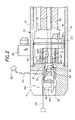
- FIG. 2 is a sectional view of a base end of the cylinder assembly with a sensor installed, and a wrench socket in position for such installation;
- FIG. 3 is a fragmentary perspective view of the base of the cylinder assembly showing the sensor installed, and with parts in section and parts broken away;
- FIG. 4 is a side view of a wrench socket as utilized with the present invention and showing a slit for extension of the sensor lead from the socket during the tightening or loosening operation;
- FIG. 5 is a partial perspective view of the exterior of a base end of the cylinder assembly with a sensor lead wire shown.
- a fluid pressure cylinder assembly indicated at 10 such as a hydraulic or pneumatic cylinder or actuator, is provided with an outer cylinder tube 12 .
- a cylinder base block 14 closes one end of cylinder tube 12 , and an extendable and retractable piston rod 16 having a rod end 18 extends through a rod end cap at the other end of the cylinder to the outside of the cylinder tube 12 .
- the piston rod 16 is connected to a piston 20 that is mounted on the interior chamber 22 of the cylinder tube 12 .
- the piston rod 16 has a reduced diameter neck 21 that passes through a bore in piston 20 .
- a shoulder 16 A is formed on piston rod 16 that bears against and supports the piston.
- a spacer 17 is shown in place over the rod 16 and against the piston, and is broken away to show the shoulder 16 A.
- the piston 20 is held on a threaded end of neck 21 of the rod 16 with a nut 42 .
- the nut 42 has an interior bore 45 that is unthreaded at a portion adjacent the outer end of the bore.
- the end of nut 42 extends outwardly beyond the end of the piston rod neck.
- the nut 42 is tightened securely to hold the piston 20 in place.
- the end of the nut 42 will abut on the inner surface of the base block when the piston and piston rod are retracted.
- the piston 20 is movable under differential pressure and the rod 16 is thus extendable and retractable under fluid pressure.
- a pump or pressure source 24 is connected through a valve 26 to direct fluid under pressure to or from a base end fitting 28 , and a rod ending fitting 30 for extension and retraction of the piston rod 16 .
- a controller 32 is shown for controlling the position or extension of the rod end 18 , and the controller receives a feedback signal for determining the extension of the piston rod 16 and the rod end 18 along a lead or line 34 that leads from a piston stroke position sensor assembly 36 shown in FIG. 2 .
- the sensor assembly 36 includes an elongated first transducer element or rod 38 , mounted at a sensor base or housing 40 .
- the piston rod 16 has a longitudinal bore 46 that receives the transducer element or rod 38 , which can be slid longitudinally into the bore 46 .
- the bore 46 extends through the neck 21 .
- the transducer element or rod 38 extends from the base end of the piston rod 16 , through neck 21 for the majority of the length of the piston rod 16 .
- the base block 14 of the cylinder assembly 10 is a block that has a base or inner wall 41 that forms the base end of the chamber or bore 22 of the cylinder tube 12 .
- the end wall 41 closes the end of the cylinder tube 12 .
- the nut 42 that threads onto neck 21 has an outer end surface that abuts on base wall 41 to form a stop for the piston 20 when the piston is retracted.
- the inner or base wall 41 of the base 14 has a center threaded bore 43 that receives and forms a support for the sensor housing 40 in the end wall 41 of the base 14 .
- the bore 43 is threaded to hold the sensor assembly 36 , including the elongated transducer rod 38 .
- the sensor housing can be sealed relative to the wall 41 with an “O” ring 44 around its periphery.
- the elongated transducer rod 38 and the sensor housing 40 are removable as a unit from the interior bore 46 in the piston rod 16 .
- the sensor assembly 36 can be any desired sensing unit that can be activated and energized, and which will provide signals that indicate the position of the piston and piston rod that are transmitted along the lead line 34 .
- Lead line 34 can contain more than one wire, as desired, but will carry signals to excite the sensor, if desired, and also will provide feedback signals indicating the position of the piston rod (and piston) relative to a reference position, as shown, the base where the piston and piston rod are in a retracted position shown in FIG. 2 .
- the end of the bore 46 in the neck 21 of the piston rod that faces the base block 14 has a counter bore 45 A that mounts a second transducer element 47 that as shown is in the form of a ring that moves (slides) along first transducer element or rod 38 with the piston 20 and piston rod 16 .
- This second element 47 cooperates with the first element 38 to provide a signal at the sensor housing, which indicates the position of the second element 47 along transducer element or rod 38 and thus the extension position of the piston rod 16 and piston rod end 18 .
- the second sensor element can be a contact that slides on the rod 38 , if a variable resistance sensor is used.
- the electronic circuitry for the sensor is provided at controller 32 .
- Rod end 18 is connected to a load or movable member represented schematically at 50 , and the cylinder block base 14 is connected to a frame support 52 .
- the distance of movement or position of the load or work member 50 can be determined by the signal indicating the position of movable second transducer element 47 relative to the stationary transducer rod 38 .
- Sensor housing 40 is installed in bore 44 using a unique method.
- the outer end of the sensor housing 40 has a hexagon configuration or hex nut 56 , and the lead 34 (which can have several wires in it) extends from the center of the sensor housing 40 .
- the cylinder base 14 has an axial access bore 58 open at the base end, and extending to the end wall 41 .
- the base 14 also has a cross bore 60 that is used for mounting a pin 62 ( FIG. 1 ) for in turn mounting the base 14 to the frame support 52 .
- the base 14 has a radial slot or slit 64 formed therein that joins the axially bore 58 , and extends radially out to one lateral side, for example, the side that contains the base end hydraulic line fitting 28 as shown in FIG. 5 .
- the slot or slit 64 has a longitudinal length opening along the side of access bore 58 and intersecting the bore 58 .
- a wrench socket 70 that has a longitudinally extending slot 72 therein is utilized, and it is attached to a suitable socket drive 74 in a conventional manner.
- the socket drive 74 has an extension shank 76 that is provided on the drive 74 , and which has a drive end that drives the socket 70 .
- the inner diameter of the access bore 58 in the base 14 is large enough relative to the outer surface of the socket so that the wrench socket 70 will slide into the bore 58 with some clearance around the outer periphery and fit over the end of housing 40 .
- the wrench socket 70 is slipped onto the hex outer configuration or nut end 56 , and the sensor lead 34 is placed through the slot 72 of the socket, so that the lead 34 extends out of the socket 70 .
- the lead 34 is extended longitudinally along or axially along the inner surface of the access bore 58 and to the outside of the drive end of the socket as shown in dotted lines in FIG. 2 .
- a suitable connector 35 is used at the end of the lead 34 , and the lead would not be of excessive length. However, it can be seen that the lead 34 will rotate with the wrench socket and sensor housing 40 inside the access bore 58 as the sensor assembly 36 is tightened in place.
- a suitable “O” ring 44 rests against a flange to seal the threaded bore 43 , so that the interior of the cylinder tube 12 is sealed or closed.
- the wrench socket 70 is removed, and the lead 34 is released from the slot 72 of the socket.
- the lead 34 then can be passed through the slot 64 from bore 58 , and connector 35 can be mated with a connection to the controller 32 .
- the lead or wire 34 is placed to the interior side of the cross bore 60 and thus between pin 62 and the sensor housing and so the lead 34 is not moved or stretched excessively if the cylinder assembly 10 pivots on the pin 62 .
- the lead is also protected by the pin 62 when the pin 62 is in place.
- the sensor assembly 36 can be installed after all operations for manufacturing the cylinder assembly 10 are done. That insures that the sensor elements will not get physically damaged or affected by welding, heat treating, painting and the like, which are necessary for manufacturing the cylinder assembly.
- the removal of the sensor assembly 36 is an opposite procedure, namely the wrench socket 70 would be put into position on the hex end of the sensor housing after the pin 62 has been removed.
- the connector 35 would be separated and the lead 34 would be extended into the slot 72 (which is an axially extending slot) of the wrench socket 70 .
- the socket would be placed over the drive end or hex end 56 of the sensor housing 40 .
- the lead 34 would be removed from slot or slit 64 and extended out the end of access bore 58 so it could be rotated without twisting. Then the socket would be driven to rotate and unthread the sensor housing 40 .
- the lead 34 would be rotating so that it would not be wound up on the wrench socket or damaged by extending out the end of the socket that is on the hex end 56 .
- the sensor housing 40 and transducer rod 38 would be removed axially after threading the sensor housing out of the bore 43 in which it is mounted in the base 14 .
- the sensor assembly 36 including transducer rod 38 , is pulled out of the cylinder base block and serviced or replaced.
- the wrench socket 70 again would be put into position on the end of the sensor housing 40 with the sensor lead extending through the slot 72 .
- the socket, sensor and the lead would be rotated as a unit to tighten the sensor housing in place.
- the socket would be removed with the lead 34 sliding out the end of the slot 72 , and placed through the slot 64 in the base 14 to be connected to a controller or similar item.
- sensors can be accommodated with the mounting in the base of the cylinder using the axially centered threaded bore in the base end.
- a magnetostrictive linear displacement sensor is shown.
- the second element 47 is a ring magnet with this type of sensor. Any type of threaded sensor housing that can be threaded into place according to the present invention using a slotted socket can be used.
- the electronics package is not included, but is part of the controller remote from the cylinder.
- Variable resistor sensors can also be used where a contact on the piston or piston rod slides along an elongated transducer element.
- the sensor again, is protected by the base block since it is in a recess, but is accessible from the exterior through the axial clearance access bore 58 pin 62 is removed.
Abstract
Description
Claims (14)
Priority Applications (1)
| Application Number | Priority Date | Filing Date | Title |
|---|---|---|---|
| US10/957,460 US7059238B2 (en) | 2003-10-17 | 2004-10-01 | Method and apparatus for stroke position sensor for hydraulic cylinder |
Applications Claiming Priority (2)
| Application Number | Priority Date | Filing Date | Title |
|---|---|---|---|
| US51258303P | 2003-10-17 | 2003-10-17 | |
| US10/957,460 US7059238B2 (en) | 2003-10-17 | 2004-10-01 | Method and apparatus for stroke position sensor for hydraulic cylinder |
Publications (2)
| Publication Number | Publication Date |
|---|---|
| US20050081710A1 US20050081710A1 (en) | 2005-04-21 |
| US7059238B2 true US7059238B2 (en) | 2006-06-13 |
Family
ID=34465364
Family Applications (1)
| Application Number | Title | Priority Date | Filing Date |
|---|---|---|---|
| US10/957,460 Expired - Fee Related US7059238B2 (en) | 2003-10-17 | 2004-10-01 | Method and apparatus for stroke position sensor for hydraulic cylinder |
Country Status (10)
| Country | Link |
|---|---|
| US (1) | US7059238B2 (en) |
| EP (1) | EP1676032B1 (en) |
| JP (1) | JP2007509290A (en) |
| KR (1) | KR101189559B1 (en) |
| CN (1) | CN100487254C (en) |
| AU (1) | AU2004282569B2 (en) |
| CA (1) | CA2542341C (en) |
| DE (1) | DE602004014960D1 (en) |
| ES (1) | ES2305874T3 (en) |
| WO (1) | WO2005038270A1 (en) |
Cited By (20)
| Publication number | Priority date | Publication date | Assignee | Title |
|---|---|---|---|---|
| DE202006012815U1 (en) * | 2006-08-17 | 2007-12-20 | Mts Sensor Technologie Gmbh & Co. Kg | travel length |
| DE102006047966A1 (en) * | 2006-07-07 | 2008-01-10 | Asm Automation Sensorik Messtechnik Gmbh | Piston position sensor e.g. magnetostrictive sensor, for e.g. hydraulic cylinder, has sliding unit made of abrasion-resistant material e.g. polyamide, with high slidability in comparison with wave guide unit of sensor unit |
| US20090271998A1 (en) * | 2008-05-02 | 2009-11-05 | Carlen Controls, Inc. | Linear Position Transducer With Wireless Read Head |
| US20100050863A1 (en) * | 2008-08-29 | 2010-03-04 | Cowan Dynamics Inc. | Fluid-powered actuator having an internal position sensor and a sensor module therefor |
| US20100095840A1 (en) * | 2008-10-21 | 2010-04-22 | Clark Equipment Company | Hydraulic cylinder rod position sensor |
| US20110303085A1 (en) * | 2009-02-05 | 2011-12-15 | Mike Heurich | Piston-Cylinder Assembly Having Integrated Measuring Device |
| US20130284016A1 (en) * | 2010-12-22 | 2013-10-31 | Knorr-Bremse Systeme Fuer Nutzfahrzeuge Gmbh | Cover for a Cylinder Arrangement, Cylinder Arrangement, and Automatic Transmission |
| US9074860B2 (en) | 2013-03-13 | 2015-07-07 | Ametek | Systems and methods for magnetostrictive sensing |
| US20160177982A1 (en) * | 2013-07-31 | 2016-06-23 | Kyb Corporation | Fluid pressure cylinder |
| US20160298659A1 (en) * | 2013-11-21 | 2016-10-13 | Westport Power Inc. | Detecting end of stroke in a hydraulic motor |
| US9482245B2 (en) | 2010-10-26 | 2016-11-01 | Jlg Industries, Inc. | Cylinder length sensor mounting/retaining assembly |
| US9945402B2 (en) | 2012-07-20 | 2018-04-17 | Borgwarner Inc. | Internal position sensor |
| US10119559B1 (en) * | 2017-03-09 | 2018-11-06 | Lockheed Martin Corporation | Fail-safe hydraulic actuator with constant force retraction springs |
| US10246946B2 (en) | 2015-03-25 | 2019-04-02 | Columbia Trailer Co., Inc. | Method and apparatus for transporting and steering a heavy load |
| US10358876B2 (en) | 2015-07-22 | 2019-07-23 | Columbia Trailer Co., Inc. | Method and apparatus for transporting and steering a heavy load |
| US10787109B2 (en) | 2016-11-11 | 2020-09-29 | Herzog Railroad Services, Inc. | System and method for operating a ballast car hopper door |
| US11067105B1 (en) * | 2020-02-21 | 2021-07-20 | Caterpillar Inc. | Flange mount cylinder sensor |
| EP3879240A1 (en) | 2020-03-13 | 2021-09-15 | Wollin GmbH | Dose volume measuring device |
| US11661126B2 (en) | 2018-08-17 | 2023-05-30 | Columbia Trailer Co., Inc. | Method and apparatus for transporting and steering a heavy load |
| US11815352B2 (en) | 2015-02-17 | 2023-11-14 | Schlumberger Technology Corporation | Apparatus and method for determining borehole size with a borehole imaging tool |
Families Citing this family (18)
| Publication number | Priority date | Publication date | Assignee | Title |
|---|---|---|---|---|
| US20090222176A1 (en) * | 2005-11-10 | 2009-09-03 | Volvo Construction Equipment Ab | Loader |
| DE102005060674C5 (en) * | 2005-12-19 | 2020-02-27 | Asm Automation Sensorik Messtechnik Gmbh | Position sensor in rod construction and procedure for exchange |
| DE102005060676B4 (en) * | 2005-12-19 | 2021-01-21 | Asm Automation Sensorik Messtechnik Gmbh | Rod-type position sensor and replacement method |
| DE102007023413B4 (en) * | 2007-05-18 | 2009-06-10 | Rehau Ag + Co. | Hydraulic power unit |
| CN102943785B (en) * | 2012-11-27 | 2015-11-11 | 湖南特力液压有限公司 | Piston cylinder and installation method thereof |
| CN103057374B (en) * | 2012-12-27 | 2016-12-28 | 三一汽车起重机械有限公司 | Hydro-pneumatic suspension system and engineering truck |
| US9188463B2 (en) * | 2013-02-05 | 2015-11-17 | General Electric Company | Hermetic electrically shielded connector |
| DE102014105154A1 (en) * | 2014-04-11 | 2015-10-15 | Mhwirth Gmbh | Method for detecting the position and / or movement of a piston in a cylinder and cylinder arrangement |
| CN104832495B (en) * | 2015-03-31 | 2016-11-30 | 徐州重型机械有限公司 | Hanging oil cylinder and crane |
| JP6071084B2 (en) * | 2015-07-02 | 2017-02-01 | Kyb株式会社 | Fluid pressure cylinder and manufacturing method thereof |
| CN105114398A (en) * | 2015-09-21 | 2015-12-02 | 海门市油威力液压工业有限责任公司 | High-response electro-hydraulic shaft controller |
| US20180155121A1 (en) * | 2016-12-06 | 2018-06-07 | R. A. Nichols Engineering | System and method for controlling vapor expansions and contractions inside of closed storage vessels |
| DE102017108855C5 (en) * | 2017-04-26 | 2023-09-07 | Asm Automation Sensorik Messtechnik Gmbh | Sensor unit and working cylinder unit with a sensor unit |
| KR101947074B1 (en) * | 2017-07-12 | 2019-02-12 | 디와이파워 주식회사 | Cushion structure of hydraulic cylinder provided with internally installed linear position sensor of piston |
| ES2959445T3 (en) * | 2019-08-09 | 2024-02-26 | Siko Gmbh | Sensor unit for a fluidic cylinder and fluidic cylinder |
| CN112872051B (en) * | 2020-12-11 | 2023-06-16 | 鞍钢股份有限公司 | Self-adaptive strong magnetic adsorption head for SONY magnetic track type magnetic ruler |
| SE2130194A1 (en) * | 2021-07-09 | 2023-01-10 | Smp Parts Ab | Quick coupling device |
| CN114278645A (en) * | 2021-12-17 | 2022-04-05 | 合肥长源液压股份有限公司 | Digital hydraulic cylinder |
Citations (34)
| Publication number | Priority date | Publication date | Assignee | Title |
|---|---|---|---|---|
| US3086414A (en) | 1961-03-01 | 1963-04-23 | Nardi Guy | Combination wrench |
| US3168853A (en) | 1962-10-08 | 1965-02-09 | Prince Richard | Hydraulic cylinder device |
| US3403365A (en) | 1964-05-04 | 1968-09-24 | Gen Electric | Shielded transducer having means to reduce core movement |
| DE2313215A1 (en) | 1972-12-21 | 1974-06-27 | Orsta Hydraulik Veb K | DEVICE FOR GETTING INFORMATION ON WORK CYLINDERS |
| US3898555A (en) | 1973-12-19 | 1975-08-05 | Tempo Instr Inc | Linear distance measuring device using a moveable magnet interacting with a sonic waveguide |
| US4096621A (en) | 1975-12-17 | 1978-06-27 | Caterpillar Tractor Co. | Method of concurrently rotating a threaded fastener and deflecting a locking tab |
| GB1601572A (en) | 1977-05-06 | 1981-10-28 | Davy Loewy Ltd | Linear displacement transducer |
| USD274881S (en) | 1982-03-25 | 1984-07-31 | Wilsey William R | Socket |
| US4523514A (en) | 1981-09-08 | 1985-06-18 | Deere & Company | Position sensing cylinder |
| US4552055A (en) | 1981-02-09 | 1985-11-12 | Prince Manufacturing Company | Power cylinder with internally mounted position indicator |
| US4632018A (en) | 1983-06-02 | 1986-12-30 | Lymburner Robert K | Fluid cylinder position sensor mounting apparatus |
| US4718647A (en) | 1980-02-20 | 1988-01-12 | Avm, Inc. | Pneumatic counterbalance with dual force |
| US4771866A (en) | 1986-04-03 | 1988-09-20 | Enertrols, Inc. | Shock absorber with proximity switch |
| US4788489A (en) | 1985-07-12 | 1988-11-29 | Nissan Motor Co., Ltd. | Position sensor for use in variable height automotive suspension or the like |
| US4952873A (en) | 1989-09-11 | 1990-08-28 | Mts Systems Corporation | Compact head, signal enhancing magnetostrictive transducer |
| US4961055A (en) | 1989-01-04 | 1990-10-02 | Vickers, Incorporated | Linear capacitance displacement transducer |
| DE9109026U1 (en) | 1991-07-22 | 1991-09-19 | Siemens Ag, 8000 Muenchen, De | |
| US5150049A (en) | 1991-06-24 | 1992-09-22 | Schuetz Tool & Die, Inc. | Magnetostrictive linear displacement transducer with temperature compensation |
| US5182980A (en) | 1992-02-05 | 1993-02-02 | Caterpillar Inc. | Hydraulic cylinder position sensor mounting apparatus |
| US5198761A (en) | 1990-03-06 | 1993-03-30 | Hitachi Construction Machinery Co., Ltd. | Temperature compensated magnetostrictive piston position detector |
| US5320325A (en) | 1993-08-02 | 1994-06-14 | Hydril Company | Position instrumented blowout preventer |
| USD355343S (en) | 1993-05-03 | 1995-02-14 | Gliddings Jr Albert | Socket for removing thermol valves |
| US5477771A (en) * | 1993-08-10 | 1995-12-26 | Black; Philip B. | Hydraulic cylinder assembly |
| US5514961A (en) | 1993-01-13 | 1996-05-07 | Festo Kg | Position detecting device for a linear drive including two magnets having like poles disposed facing each other for concentrating the flux at one point |
| US5583433A (en) | 1993-02-19 | 1996-12-10 | Macome Corporation | Apparatus for measuring length using ultrasonic delay line and matching a phase of drive pulse with reflected pulse |
| US5717330A (en) | 1996-03-07 | 1998-02-10 | Moreau; Terence J. | Magnetostrictive linear displacement transducer utilizing axial strain pulses |
| US5952823A (en) | 1996-03-22 | 1999-09-14 | Mts Systems Corporation | Magnetostrictive linear displacement transducer for a shock absorber |
| US5977778A (en) | 1996-11-27 | 1999-11-02 | Case Corporation | Method and apparatus for sensing piston position |
| US5998992A (en) | 1997-01-30 | 1999-12-07 | Macome Corp. | Length measuring apparatus employing magnetostrictive delay line |
| US6058813A (en) | 1998-12-22 | 2000-05-09 | Bryant; Paul | Locknut wrench |
| US6122997A (en) | 1994-08-26 | 2000-09-26 | Altura; Dan | Adapter for precise tightening of fluid tube fittings |
| EP1070856A1 (en) | 1999-07-19 | 2001-01-24 | CLAAS Industrietechnik GmbH | Piston position indicator |
| DE10044984A1 (en) | 2000-09-11 | 2002-03-21 | Mannesmann Rexroth Ag | Hydraulic cylinder |
| US6509733B2 (en) | 2000-12-20 | 2003-01-21 | Caterpillar Inc | Fluid cylinder with embedded positioning sensor |
-
2004
- 2004-10-01 US US10/957,460 patent/US7059238B2/en not_active Expired - Fee Related
- 2004-10-14 WO PCT/US2004/034006 patent/WO2005038270A1/en active Application Filing
- 2004-10-14 KR KR1020067009181A patent/KR101189559B1/en not_active IP Right Cessation
- 2004-10-14 EP EP04795200A patent/EP1676032B1/en not_active Expired - Fee Related
- 2004-10-14 JP JP2006535331A patent/JP2007509290A/en active Pending
- 2004-10-14 CN CNB2004800305790A patent/CN100487254C/en not_active Expired - Fee Related
- 2004-10-14 AU AU2004282569A patent/AU2004282569B2/en not_active Ceased
- 2004-10-14 CA CA2542341A patent/CA2542341C/en not_active Expired - Fee Related
- 2004-10-14 ES ES04795200T patent/ES2305874T3/en active Active
- 2004-10-14 DE DE602004014960T patent/DE602004014960D1/en active Active
Patent Citations (34)
| Publication number | Priority date | Publication date | Assignee | Title |
|---|---|---|---|---|
| US3086414A (en) | 1961-03-01 | 1963-04-23 | Nardi Guy | Combination wrench |
| US3168853A (en) | 1962-10-08 | 1965-02-09 | Prince Richard | Hydraulic cylinder device |
| US3403365A (en) | 1964-05-04 | 1968-09-24 | Gen Electric | Shielded transducer having means to reduce core movement |
| DE2313215A1 (en) | 1972-12-21 | 1974-06-27 | Orsta Hydraulik Veb K | DEVICE FOR GETTING INFORMATION ON WORK CYLINDERS |
| US3898555A (en) | 1973-12-19 | 1975-08-05 | Tempo Instr Inc | Linear distance measuring device using a moveable magnet interacting with a sonic waveguide |
| US4096621A (en) | 1975-12-17 | 1978-06-27 | Caterpillar Tractor Co. | Method of concurrently rotating a threaded fastener and deflecting a locking tab |
| GB1601572A (en) | 1977-05-06 | 1981-10-28 | Davy Loewy Ltd | Linear displacement transducer |
| US4718647A (en) | 1980-02-20 | 1988-01-12 | Avm, Inc. | Pneumatic counterbalance with dual force |
| US4552055A (en) | 1981-02-09 | 1985-11-12 | Prince Manufacturing Company | Power cylinder with internally mounted position indicator |
| US4523514A (en) | 1981-09-08 | 1985-06-18 | Deere & Company | Position sensing cylinder |
| USD274881S (en) | 1982-03-25 | 1984-07-31 | Wilsey William R | Socket |
| US4632018A (en) | 1983-06-02 | 1986-12-30 | Lymburner Robert K | Fluid cylinder position sensor mounting apparatus |
| US4788489A (en) | 1985-07-12 | 1988-11-29 | Nissan Motor Co., Ltd. | Position sensor for use in variable height automotive suspension or the like |
| US4771866A (en) | 1986-04-03 | 1988-09-20 | Enertrols, Inc. | Shock absorber with proximity switch |
| US4961055A (en) | 1989-01-04 | 1990-10-02 | Vickers, Incorporated | Linear capacitance displacement transducer |
| US4952873A (en) | 1989-09-11 | 1990-08-28 | Mts Systems Corporation | Compact head, signal enhancing magnetostrictive transducer |
| US5198761A (en) | 1990-03-06 | 1993-03-30 | Hitachi Construction Machinery Co., Ltd. | Temperature compensated magnetostrictive piston position detector |
| US5150049A (en) | 1991-06-24 | 1992-09-22 | Schuetz Tool & Die, Inc. | Magnetostrictive linear displacement transducer with temperature compensation |
| DE9109026U1 (en) | 1991-07-22 | 1991-09-19 | Siemens Ag, 8000 Muenchen, De | |
| US5182980A (en) | 1992-02-05 | 1993-02-02 | Caterpillar Inc. | Hydraulic cylinder position sensor mounting apparatus |
| US5514961A (en) | 1993-01-13 | 1996-05-07 | Festo Kg | Position detecting device for a linear drive including two magnets having like poles disposed facing each other for concentrating the flux at one point |
| US5583433A (en) | 1993-02-19 | 1996-12-10 | Macome Corporation | Apparatus for measuring length using ultrasonic delay line and matching a phase of drive pulse with reflected pulse |
| USD355343S (en) | 1993-05-03 | 1995-02-14 | Gliddings Jr Albert | Socket for removing thermol valves |
| US5320325A (en) | 1993-08-02 | 1994-06-14 | Hydril Company | Position instrumented blowout preventer |
| US5477771A (en) * | 1993-08-10 | 1995-12-26 | Black; Philip B. | Hydraulic cylinder assembly |
| US6122997A (en) | 1994-08-26 | 2000-09-26 | Altura; Dan | Adapter for precise tightening of fluid tube fittings |
| US5717330A (en) | 1996-03-07 | 1998-02-10 | Moreau; Terence J. | Magnetostrictive linear displacement transducer utilizing axial strain pulses |
| US5952823A (en) | 1996-03-22 | 1999-09-14 | Mts Systems Corporation | Magnetostrictive linear displacement transducer for a shock absorber |
| US5977778A (en) | 1996-11-27 | 1999-11-02 | Case Corporation | Method and apparatus for sensing piston position |
| US5998992A (en) | 1997-01-30 | 1999-12-07 | Macome Corp. | Length measuring apparatus employing magnetostrictive delay line |
| US6058813A (en) | 1998-12-22 | 2000-05-09 | Bryant; Paul | Locknut wrench |
| EP1070856A1 (en) | 1999-07-19 | 2001-01-24 | CLAAS Industrietechnik GmbH | Piston position indicator |
| DE10044984A1 (en) | 2000-09-11 | 2002-03-21 | Mannesmann Rexroth Ag | Hydraulic cylinder |
| US6509733B2 (en) | 2000-12-20 | 2003-01-21 | Caterpillar Inc | Fluid cylinder with embedded positioning sensor |
Cited By (32)
| Publication number | Priority date | Publication date | Assignee | Title |
|---|---|---|---|---|
| DE102006047966A1 (en) * | 2006-07-07 | 2008-01-10 | Asm Automation Sensorik Messtechnik Gmbh | Piston position sensor e.g. magnetostrictive sensor, for e.g. hydraulic cylinder, has sliding unit made of abrasion-resistant material e.g. polyamide, with high slidability in comparison with wave guide unit of sensor unit |
| DE202006012815U1 (en) * | 2006-08-17 | 2007-12-20 | Mts Sensor Technologie Gmbh & Co. Kg | travel length |
| WO2008019838A1 (en) * | 2006-08-17 | 2008-02-21 | Mts Sensor Technologie Gmbh & Co. Kg | Displacement sensor, and assembly thereof |
| US7971487B2 (en) | 2008-05-02 | 2011-07-05 | Carlen Controls, Inc. | Linear position transducer with wireless read head |
| US20090271998A1 (en) * | 2008-05-02 | 2009-11-05 | Carlen Controls, Inc. | Linear Position Transducer With Wireless Read Head |
| US20100050863A1 (en) * | 2008-08-29 | 2010-03-04 | Cowan Dynamics Inc. | Fluid-powered actuator having an internal position sensor and a sensor module therefor |
| US8448563B2 (en) | 2008-08-29 | 2013-05-28 | Cowan Dynamics Inc. | Fluid-powered actuator having an internal position sensor and a sensor module therefor |
| US20100095840A1 (en) * | 2008-10-21 | 2010-04-22 | Clark Equipment Company | Hydraulic cylinder rod position sensor |
| US8100045B2 (en) | 2008-10-21 | 2012-01-24 | Clark Equipment Company | Hydraulic cylinder rod position sensor |
| US20110303085A1 (en) * | 2009-02-05 | 2011-12-15 | Mike Heurich | Piston-Cylinder Assembly Having Integrated Measuring Device |
| US8997630B2 (en) * | 2009-02-05 | 2015-04-07 | Wabco Gmbh | Piston-cylinder assembly having integrated measuring device |
| US20150176615A1 (en) * | 2009-02-05 | 2015-06-25 | Wabco Gmbh | Piston-cylinder assembly having integrated measuring device |
| US9771958B2 (en) * | 2009-02-05 | 2017-09-26 | Wabco Gmbh | Piston cylinder assembly having integrated measuring device |
| EP2633159A4 (en) * | 2010-10-26 | 2017-10-25 | JLG Industries Inc. | Cylinder length sensor mounting/retaining assembly |
| US9482245B2 (en) | 2010-10-26 | 2016-11-01 | Jlg Industries, Inc. | Cylinder length sensor mounting/retaining assembly |
| US20130284016A1 (en) * | 2010-12-22 | 2013-10-31 | Knorr-Bremse Systeme Fuer Nutzfahrzeuge Gmbh | Cover for a Cylinder Arrangement, Cylinder Arrangement, and Automatic Transmission |
| US9334961B2 (en) * | 2010-12-22 | 2016-05-10 | Knorr-Bremse Systeme Fuer Nutzfahrzeuge Gmbh | Cover for a cylinder arrangement, cylinder arrangement, and automatic transmission |
| US9945402B2 (en) | 2012-07-20 | 2018-04-17 | Borgwarner Inc. | Internal position sensor |
| US9074860B2 (en) | 2013-03-13 | 2015-07-07 | Ametek | Systems and methods for magnetostrictive sensing |
| US20160177982A1 (en) * | 2013-07-31 | 2016-06-23 | Kyb Corporation | Fluid pressure cylinder |
| US9879703B2 (en) * | 2013-07-31 | 2018-01-30 | Kyb Corporation | Fluid pressure cylinder |
| US20160298659A1 (en) * | 2013-11-21 | 2016-10-13 | Westport Power Inc. | Detecting end of stroke in a hydraulic motor |
| US10385890B2 (en) * | 2013-11-21 | 2019-08-20 | Westport Power Inc. | Detecting end of stroke in a hydraulic motor |
| US11815352B2 (en) | 2015-02-17 | 2023-11-14 | Schlumberger Technology Corporation | Apparatus and method for determining borehole size with a borehole imaging tool |
| US10246946B2 (en) | 2015-03-25 | 2019-04-02 | Columbia Trailer Co., Inc. | Method and apparatus for transporting and steering a heavy load |
| US10358876B2 (en) | 2015-07-22 | 2019-07-23 | Columbia Trailer Co., Inc. | Method and apparatus for transporting and steering a heavy load |
| US10787109B2 (en) | 2016-11-11 | 2020-09-29 | Herzog Railroad Services, Inc. | System and method for operating a ballast car hopper door |
| US10119559B1 (en) * | 2017-03-09 | 2018-11-06 | Lockheed Martin Corporation | Fail-safe hydraulic actuator with constant force retraction springs |
| US11661126B2 (en) | 2018-08-17 | 2023-05-30 | Columbia Trailer Co., Inc. | Method and apparatus for transporting and steering a heavy load |
| US11067105B1 (en) * | 2020-02-21 | 2021-07-20 | Caterpillar Inc. | Flange mount cylinder sensor |
| EP3879240A1 (en) | 2020-03-13 | 2021-09-15 | Wollin GmbH | Dose volume measuring device |
| DE102020107647A1 (en) | 2020-03-13 | 2021-09-16 | Wollin Gmbh | Dosing volume measuring device |
Also Published As
| Publication number | Publication date |
|---|---|
| CN1867777A (en) | 2006-11-22 |
| AU2004282569B2 (en) | 2010-06-10 |
| JP2007509290A (en) | 2007-04-12 |
| CA2542341C (en) | 2011-11-29 |
| ES2305874T3 (en) | 2008-11-01 |
| KR20060126465A (en) | 2006-12-07 |
| WO2005038270A1 (en) | 2005-04-28 |
| US20050081710A1 (en) | 2005-04-21 |
| DE602004014960D1 (en) | 2008-08-21 |
| KR101189559B1 (en) | 2012-10-11 |
| CA2542341A1 (en) | 2005-04-28 |
| EP1676032A1 (en) | 2006-07-05 |
| CN100487254C (en) | 2009-05-13 |
| AU2004282569A1 (en) | 2005-04-28 |
| EP1676032B1 (en) | 2008-07-09 |
Similar Documents
| Publication | Publication Date | Title |
|---|---|---|
| US7059238B2 (en) | Method and apparatus for stroke position sensor for hydraulic cylinder | |
| US6941827B2 (en) | Mounting apparatus and method for cylinder position sensor | |
| US8448563B2 (en) | Fluid-powered actuator having an internal position sensor and a sensor module therefor | |
| US7023199B2 (en) | Position sensing cylinder cap for ease of service and assembly | |
| US20010000832A1 (en) | Tool system for disassembling sucker rods | |
| CN107923552B (en) | Rotary actuated valve with position indicator | |
| US4982652A (en) | Fluid operated actuator with recessed position sensor and recessed end cap fastener | |
| CA2367202A1 (en) | Pressure-containing plug for a tubular passageway | |
| CN104913101A (en) | Actuator apparatus with internal tubing and anti-rotation mechanism | |
| US20070139039A1 (en) | Stick position sensor and replacement process | |
| CN1295199A (en) | Fluid pressure cylinder capable of adjusting stroke | |
| US7661663B2 (en) | Vibration damper having a buffer spring | |
| US7162947B2 (en) | Mount for cylinder position sensor | |
| US6345568B1 (en) | Fluid pressure device with reversible mounting mechanism | |
| JP6677751B2 (en) | Fluid leak detection equipment and reciprocating fluid pressure equipment | |
| CN108779873B (en) | Valve operating system | |
| CN207961122U (en) | pneumatic valve actuator | |
| CN104132022B (en) | A kind of simple servo-cylinder | |
| JPH08329803A (en) | Control switch | |
| CN1382933A (en) | Valve |
Legal Events
| Date | Code | Title | Description |
|---|---|---|---|
| AS | Assignment |
Owner name: CLARK EQUIPMENT COMPANY, NEW JERSEY Free format text: ASSIGNMENT OF ASSIGNORS INTEREST;ASSIGNORS:ALBRIGHT, LARRY E.;BARES, MARK F.;SHELBOURN, WILLIAM C.;AND OTHERS;REEL/FRAME:015868/0557;SIGNING DATES FROM 20040922 TO 20040928 |
|
| AS | Assignment |
Owner name: HSBC BANK PLC, UNITED KINGDOM Free format text: SECURITY AGREEMENT;ASSIGNOR:CLARK EQUIPMENT COMPANY;REEL/FRAME:020582/0664 Effective date: 20080226 Owner name: HSBC BANK PLC,UNITED KINGDOM Free format text: SECURITY AGREEMENT;ASSIGNOR:CLARK EQUIPMENT COMPANY;REEL/FRAME:020582/0664 Effective date: 20080226 |
|
| FPAY | Fee payment |
Year of fee payment: 4 |
|
| AS | Assignment |
Owner name: CLARK EQUIPMENT COMPANY, NORTH DAKOTA Free format text: RELEASE BY SECURED PARTY;ASSIGNOR:HSBC BANK PLC;REEL/FRAME:028848/0288 Effective date: 20120808 |
|
| FPAY | Fee payment |
Year of fee payment: 8 |
|
| AS | Assignment |
Owner name: JPMORGAN CHASE BANK, N.A., AS ADMINISTRATIVE AGENT Free format text: PATENT SECURITY AGREEMENT-TERM LOAN;ASSIGNORS:DOOSAN INFRACORE INTERNATIONAL, INC.;CLARK EQUIPMENT COMPANY;REEL/FRAME:033085/0916 Effective date: 20140528 Owner name: JPMORGAN CHASE BANK, N.A., AS ADMINISTRATIVE AGENT Free format text: PATENT SECURITY AGREEMENT-ABL;ASSIGNORS:DOOSAN INFRACORE INTERNATIONAL, INC.;CLARK EQUIPMENT COMPANY;REEL/FRAME:033085/0873 Effective date: 20140528 |
|
| AS | Assignment |
Owner name: CLARK EQUIPMENT COMPANY, DELAWARE Free format text: MERGER;ASSIGNORS:DOOSAN INFRACORE INTERNATIONAL, INC.;CLARK EQUIPMENT COMPANY;REEL/FRAME:042500/0899 Effective date: 20160630 |
|
| AS | Assignment |
Owner name: CLARK EQUIPMENT COMPANY, DELAWARE Free format text: RELEASE OF PATENT SECURITY AGREEMENT-TERM LOAN;ASSIGNOR:JPMORGAN CHASE BANK, N.A., AS ADMINISTRATIVE AGENT;REEL/FRAME:042563/0801 Effective date: 20170518 Owner name: CLARK EQUIPMENT COMPANY, DELAWARE Free format text: RELEASE OF PATENT SECURITY AGREEMENT-ABL;ASSIGNOR:JPMORGAN CHASE BANK, N.A., AS ADMINISTRATIVE AGENT;REEL/FRAME:042563/0747 Effective date: 20170518 |
|
| AS | Assignment |
Owner name: BANK OF AMERICA, N.A., AS ADMINISTRATIVE AGENT, NE Free format text: PATENT SECURITY AGREEMENT (ABL);ASSIGNOR:CLARK EQUIPMENT COMPANY;REEL/FRAME:042583/0886 Effective date: 20170518 Owner name: BANK OF AMERICA, N.A., AS ADMINISTRATIVE AGENT, NE Free format text: PATENT SECURITY AGREEMENT (TERM LOAN);ASSIGNOR:CLARK EQUIPMENT COMPANY;REEL/FRAME:042583/0863 Effective date: 20170518 Owner name: BANK OF AMERICA, N.A., AS ADMINISTRATIVE AGENT, NEW YORK Free format text: PATENT SECURITY AGREEMENT (ABL);ASSIGNOR:CLARK EQUIPMENT COMPANY;REEL/FRAME:042583/0886 Effective date: 20170518 Owner name: BANK OF AMERICA, N.A., AS ADMINISTRATIVE AGENT, NEW YORK Free format text: PATENT SECURITY AGREEMENT (TERM LOAN);ASSIGNOR:CLARK EQUIPMENT COMPANY;REEL/FRAME:042583/0863 Effective date: 20170518 |
|
| FEPP | Fee payment procedure |
Free format text: MAINTENANCE FEE REMINDER MAILED (ORIGINAL EVENT CODE: REM.) |
|
| LAPS | Lapse for failure to pay maintenance fees |
Free format text: PATENT EXPIRED FOR FAILURE TO PAY MAINTENANCE FEES (ORIGINAL EVENT CODE: EXP.) |
|
| STCH | Information on status: patent discontinuation |
Free format text: PATENT EXPIRED DUE TO NONPAYMENT OF MAINTENANCE FEES UNDER 37 CFR 1.362 |
|
| FP | Lapsed due to failure to pay maintenance fee |
Effective date: 20180613 |
|
| AS | Assignment |
Owner name: CLARK EQUIPMENT COMPANY, NORTH DAKOTA Free format text: RELEASE OF SECURITY INTEREST IN PATENTS PREVIOUSLY RECORDED AT REEL/FRAME (042583/0863);ASSIGNOR:BANK OF AMERICA, N.A., AS ADMINISTRATIVE AGENT;REEL/FRAME:060110/0065 Effective date: 20220420 |
|
| AS | Assignment |
Owner name: CLARK EQUIPMENT COMPANY, NORTH DAKOTA Free format text: RELEASE OF SECURITY IN PATENTS PREVIOUSLY RECORDED AT REEL/FRAME 042583/0886;ASSIGNOR:BANK OF AMERICA, N.A.;REEL/FRAME:061365/0464 Effective date: 20220420 |