US7057376B2 - Power management system for vehicles - Google Patents
Power management system for vehicles Download PDFInfo
- Publication number
- US7057376B2 US7057376B2 US11/035,831 US3583105A US7057376B2 US 7057376 B2 US7057376 B2 US 7057376B2 US 3583105 A US3583105 A US 3583105A US 7057376 B2 US7057376 B2 US 7057376B2
- Authority
- US
- United States
- Prior art keywords
- bus
- converter
- power
- battery
- management system
- Prior art date
- Legal status (The legal status is an assumption and is not a legal conclusion. Google has not performed a legal analysis and makes no representation as to the accuracy of the status listed.)
- Expired - Fee Related
Links
Images


Classifications
-
- H—ELECTRICITY
- H02—GENERATION; CONVERSION OR DISTRIBUTION OF ELECTRIC POWER
- H02J—CIRCUIT ARRANGEMENTS OR SYSTEMS FOR SUPPLYING OR DISTRIBUTING ELECTRIC POWER; SYSTEMS FOR STORING ELECTRIC ENERGY
- H02J1/00—Circuit arrangements for dc mains or dc distribution networks
- H02J1/10—Parallel operation of dc sources
- H02J1/102—Parallel operation of dc sources being switching converters
-
- B—PERFORMING OPERATIONS; TRANSPORTING
- B60—VEHICLES IN GENERAL
- B60R—VEHICLES, VEHICLE FITTINGS, OR VEHICLE PARTS, NOT OTHERWISE PROVIDED FOR
- B60R16/00—Electric or fluid circuits specially adapted for vehicles and not otherwise provided for; Arrangement of elements of electric or fluid circuits specially adapted for vehicles and not otherwise provided for
- B60R16/02—Electric or fluid circuits specially adapted for vehicles and not otherwise provided for; Arrangement of elements of electric or fluid circuits specially adapted for vehicles and not otherwise provided for electric constitutive elements
- B60R16/03—Electric or fluid circuits specially adapted for vehicles and not otherwise provided for; Arrangement of elements of electric or fluid circuits specially adapted for vehicles and not otherwise provided for electric constitutive elements for supply of electrical power to vehicle subsystems or for
-
- H—ELECTRICITY
- H02—GENERATION; CONVERSION OR DISTRIBUTION OF ELECTRIC POWER
- H02J—CIRCUIT ARRANGEMENTS OR SYSTEMS FOR SUPPLYING OR DISTRIBUTING ELECTRIC POWER; SYSTEMS FOR STORING ELECTRIC ENERGY
- H02J1/00—Circuit arrangements for dc mains or dc distribution networks
- H02J1/08—Three-wire systems; Systems having more than three wires
- H02J1/082—Plural DC voltage, e.g. DC supply voltage with at least two different DC voltage levels
-
- H—ELECTRICITY
- H02—GENERATION; CONVERSION OR DISTRIBUTION OF ELECTRIC POWER
- H02J—CIRCUIT ARRANGEMENTS OR SYSTEMS FOR SUPPLYING OR DISTRIBUTING ELECTRIC POWER; SYSTEMS FOR STORING ELECTRIC ENERGY
- H02J4/00—Circuit arrangements for mains or distribution networks not specified as ac or dc
-
- H—ELECTRICITY
- H02—GENERATION; CONVERSION OR DISTRIBUTION OF ELECTRIC POWER
- H02J—CIRCUIT ARRANGEMENTS OR SYSTEMS FOR SUPPLYING OR DISTRIBUTING ELECTRIC POWER; SYSTEMS FOR STORING ELECTRIC ENERGY
- H02J2310/00—The network for supplying or distributing electric power characterised by its spatial reach or by the load
- H02J2310/40—The network being an on-board power network, i.e. within a vehicle
- H02J2310/46—The network being an on-board power network, i.e. within a vehicle for ICE-powered road vehicles
Definitions
- This invention relates to a system for providing and controlling electric power.
- this invention relates to power management of a vehicle electrical power system.
- a typical vehicle power system consists of a battery, an alternator to charge the battery and to augment power supplied by the battery, and one or more distribution buses to power a variety of loads connected to the system.
- the field voltage of the alternator is controlled to regulate the output of the alternator and in turn regulate the voltage of the power distribution bus, which is usually on the order of about 14 volts DC or 28 volts DC.
- the alternator must operate at a voltage compatible with the battery, even if most of the power provided by the alternator is consumed by a load that is configured to optimally operate at a different supply voltage.
- the battery voltage is necessarily the same as the distribution bus voltage regardless of the battery's temperature or state of charge, causing degradation of the battery and reducing its useful life. Further, the charging and discharging of the battery is relatively uncontrolled.
- AC power In addition to DC power, portable alternating current (“AC”) power is a desired resource for many specialized vehicles. For example, emergency vehicles may require AC power to operate medical equipment carried on board the vehicle. AC power is likewise used in utility and construction vehicles to operate tools and equipment. Another common use for vehicle-based AC power is in long-haul transport tractor-trailer trucks having a sleeper compartment wherein AC power may be used to operate convenience accessories such as electric razors, televisions and microwaves. Similarly, recreational camping vehicles (“RVs”) use AC power to operate the various household accessories installed in the RV as well as those that may be carried by the passengers.
- RVs recreational camping vehicles
- Static inverters are commonly used to generate portable AC electrical power from a DC power source. Such inverters are relatively lightweight and have no moving parts to wear out. In addition, inverters do not require a fueled engine such as the vehicle's prime mover to produce power, are quiet, and do not produce fumes. Inverters are also more efficient than comparable power sources, such as motor-driven generators. However, inverters suffer from a limitation in that their output power, measured in volt-amps (“VA”) or watts, may be constrained under some conditions.
- VA volt-amps
- an inverter that derives its input power from a vehicle's alternator system may not be able to deliver the full amount of electrical power demanded by a load when the vehicle is at idle since the power delivery capacity of an alternator varies directly with the vehicle's engine speed.
- accessory electrification includes power steering pumps, hydraulic drives, engine cooling fans, air conditioning compressors, oil and coolant pumps, and air compressors.
- Advantages of accessory electrification include a reduction in engine loading, which facilitates greater engine performance, increased flexibility in locating and mounting the accessories in the vehicle, reduced fuel consumption, more efficient accessory operation made possible by optimizing the location and wiring of the accessories, and reduced vehicle emissions corresponding to reduced engine loading and fuel consumption.
- a vehicle may have a first battery system for operating a starter to “crank,” or start, the engine and a second battery system for powering accessories.
- the discharge and load characteristics can vary considerably between the cranking and accessory batteries.
- the cranking batteries are intended to provide high current for a relatively short period of time to start the engine, while the accessory batteries are used to provide a smaller amount of current to the vehicle's accessories for a relatively long period of time.
- the types of batteries used for cranking and for powering accessories may also differ.
- a cranking battery may use flooded lead-acid batteries while the accessory battery may use deep-cycle absorbed glass mat (“AGM”) batteries.
- AGM deep-cycle absorbed glass mat
- Each type of battery can have differing charge requirements, as well.
- the system may be flexibly configured using various arrangements of DC to AC inverters, DC to DC converters AC to DC converters, DC to AC converters and AC to AC converters, one or more batteries, and a control portion to provide an AC bus, a primary DC bus and a secondary DC bus.
- the control portion monitors the status of the buses, inverters and converters and controls the operation of the inverters and converters to supply and regulate the power supplied by the buses.
- the inverters and converters may be bidirectional, allowing power to be transferred between buses.
- the system comprises a high-voltage DC bus, a DC to AC inverter connected between the high-voltage DC bus and an AC bus, and a DC to DC converter connected between the high-voltage DC bus and a battery.
- the DC to DC converter and the battery are further connected to a DC bus and to a control portion.
- the control portion is responsive to the status of at least one of the high-voltage DC bus, DC to AC inverter, AC bus, DC to DC converter, battery and primary DC bus.
- the control portion in turn controls the operation of at least one of the DC to AC inverter and the DC to DC converter to supply and/or regulate at least one of the voltage and current of at least one of the AC bus and DC bus.
- the system comprises a high-voltage DC bus, a DC to AC inverter connected between the high-voltage DC bus and an AC bus, and a first DC to DC converter connected between the high-voltage DC bus and a battery.
- the first DC to DC converter and the battery are further connected to a primary DC bus.
- a second DC to DC converter is connected between the primary DC bus and a secondary DC bus.
- the system also includes a control portion.
- the control portion is responsive to the status of at least one of the high-voltage DC bus, DC to AC inverter, AC bus, first DC to DC converter, battery, primary DC bus, second DC to DC converter and secondary DC bus.
- the control portion in turn controls the operation of at least one of the DC to AC inverter, first DC to DC converter and second DC to DC converter to supply and/or regulate at least one of the voltage and current of at least one of the AC bus, primary DC bus and secondary DC bus.
- Still another aspect of the present invention is another configuration of an improved power management system for a vehicle.
- the system comprises a high-voltage DC bus, a DC to AC inverter connected between the high-voltage DC bus and an AC bus, and a first DC to DC converter connected between the high-voltage DC bus and a first battery.
- the first DC to DC converter and the first battery are further connected to a primary DC bus.
- a second DC to DC converter is connected between the primary DC bus and a second battery.
- the second DC to DC converter and the second battery are further connected to a secondary DC bus.
- the system also includes a control portion.
- control portion is responsive to the status of at least one of the high-voltage DC bus, DC to AC inverter, AC bus, first DC to DC converter, first battery, primary DC bus, second DC to DC converter, second battery and secondary DC bus.
- the control portion in turn controls the operation of at least one of the DC to AC inverter, first DC to DC converter and second DC to DC converter to supply and/or regulate at least one of the voltage and current of at least one of the AC bus, primary DC bus and secondary DC bus.
- Yet another aspect of the present invention is another configuration of an improved power management system for a vehicle.
- the system comprises an AC to AC converter connected between an AC power source and an AC bus, and an AC to DC converter connected between the AC bus and a first battery.
- the AC to DC converter and the first battery are further connected to a primary DC bus.
- a DC to DC converter is connected between the primary DC bus and a second battery.
- the DC to DC converter and the second battery are further connected to a secondary DC bus.
- the system also includes a control portion.
- the control portion is responsive to the status of at least one of the AC power source, AC to AC converter, AC bus, AC to DC converter, first battery, primary DC bus, DC to DC converter, second battery, and secondary DC bus.
- the control portion in turn controls the operation of at least one of the AC to AC converter, AC to DC converter, and DC to DC converter to supply and/or regulate at least one of the voltage and current of at least one of the AC bus, primary DC bus and secondary DC bus.
- Still another aspect of the present invention is yet another configuration of an improved power management system for a vehicle.
- the system comprises a DC to AC inverter connected between a DC power source and an AC bus, and a first battery connected to the DC power source.
- the first battery is further connected to a primary DC bus.
- a DC to DC converter is connected between the primary DC bus and a second battery.
- the DC to DC converter and the second battery are further connected to a secondary DC bus.
- the system also includes a control portion.
- the control portion is responsive to the status of at least one of the DC power source, DC to AC inverter, AC bus, first battery, primary DC bus, DC to DC converter, second battery and secondary DC bus.
- the control portion in turn controls the operation of at least one of the DC to AC inverter and the DC to DC converter to supply and/or regulate at least one of the voltage and current of at least one of the AC bus, primary DC bus and secondary DC bus.
- FIG. 1A is a schematic block circuit diagram of a power management system having a power conversion topology according to an embodiment of the present invention
- FIG. 1B is a schematic block circuit diagram of a power management system having a power conversion topology according to another embodiment of the present invention
- FIG. 2 is a schematic block circuit diagram of a power management system having a power conversion topology according to yet another embodiment of the present invention
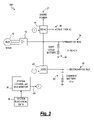
- FIG. 3 is a schematic block circuit diagram of a power management system having a power conversion topology according to still another embodiment of the present invention.
- FIG. 4A is a schematic block circuit diagram focusing on a cascaded DC/DC power conversion topology for a power management system according to an embodiment of the present invention
- FIG. 4B is a schematic block circuit diagram focusing on a multiple-output DC/DC power conversion topology for a power management system according to another embodiment of the present invention.
- FIG. 5 is a schematic block diagram of an example switching circuit for the DC/DC converter topology of FIG. 4B ;
- FIG. 6 is a top plan view of the general layout of the components of a power converter according to an embodiment of the present invention.
- the present invention comprises varying configurations of a vehicle power management system as discussed below and shown in the accompanying figures.
- the preferred configuration of the power management system for a particular vehicle depends upon the type and quantity of input power available and the output power requirements for the vehicle.
- an improved power management system 10 is depicted according to an embodiment of the present invention.
- High-voltage AC generated by an alternator 12 is rectified to DC by a rectifier 14 , forming a high voltage DC bus 16 .
- a high voltage alternator 12 and bus 16 is preferable for increased alternator efficiency and for voltage-changing flexibility during subsequent power conversion.
- a DC to AC (“DC/AC”) inverter 18 receives input voltage from high voltage bus 16 and converts the input DC voltage to an AC voltage to power vehicle accessories connected to an AC bus 28 .
- a first DC to DC (“DC/DC”) converter 20 receives input power from high voltage bus 16 and converts the input power to a predetermined output voltage with a predetermined current capacity.
- the output of converter 20 forms a primary bus 34 in conjunction with a battery 30 to power devices connected to the primary bus, such as a starter for the vehicle's engine.
- a second DC/DC converter 22 receives input power from primary bus 34 and converts the input power to a predetermined voltage and current capacity.
- the output of converter 22 forms a lower-voltage secondary bus 24 to provide power to devices connected to the secondary bus, such as accessories.
- a system controller and monitor 36 monitors system data 38 relating to the operational status of various portions of system 10 , i.e., voltage and current at the various sub-system inputs and outputs, including, but not limited to, alternator 12 , high voltage bus 16 , primary bus 34 , secondary bus 24 , AC bus 28 , DC/AC converter 18 , DC/DC converters 20 , 22 and battery 30 .
- System data 38 may further include data relating to system faults, commands from an external source, such as user input controls, and so on.
- Controller 36 is responsive to the system data 38 in a predetermined manner to control the operation of inverter 18 and converters 20 , 22 to regulate at least one of the voltage and current of at least one of the AC bus 28 , primary bus 34 and secondary bus 24 , and to charge battery 30 .
- primary bus 34 preferably provides power for high-power loads such as the starter motor of the vehicle's engine
- secondary bus 24 provides power to relatively low-power systems, such as an engine control unit (“ECU”), for example.
- ECU engine control unit
- Inverter 18 may directly convert the high voltage DC of bus 16 to a corresponding high voltage AC without the need for a step-up transformer, thus reducing system weight and cost. Inverter 18 must be rated at the full AC output specification, since the inverter is the only source of AC power output. For example, if 10 kW of AC output power is required from system 10 , inverter 18 must be configured with a large enough capacity to supply the entire 10 kW. Inverter 18 may be bidirectional and thus additionally capable of converting externally-supplied AC power (i.e., shore power 21 ) to a high voltage DC and supplying the high voltage DC to bus 16 . Thus, an external input AC voltage to inverter 18 may be rectified and supplied to high voltage bus 16 . DC/DC converter 20 may, in turn, utilize this energy to charge battery 30 , supply primary bus 34 and supply power to secondary bus 24 through DC/DC converter 22 during times when power from alternator 12 is unavailable, such as when the vehicle's engine is not operating.
- DC/DC converter 20 may,
- DC/DC converter 20 receives input power from high voltage bus 16 and converts the input power to a voltage and current suitable for charging battery 30 and providing power to high-power accessories connected to primary bus 34 .
- DC/DC converter 20 may be bidirectional, thus additionally capable of augmenting alternator 12 by converting power from battery 30 (and/or an external source of power connected to primary bus 34 ) to a high voltage compatible with high voltage bus 16 during periods of high load demand on inverter 18 .
- the amount of available additional power supplied to bus 16 by DC/DC converter 20 is limited by the capacity of the DC/DC converter.
- DC/DC converter 22 receives input power from primary bus 34 and converts the input power to a predetermined output voltage and current capacity.
- the output forms secondary DC bus 24 .
- Secondary bus 24 may be a lower voltage that primary bus 34 , and may or may not be augmented by a battery (not shown).
- Secondary bus 24 preferably provides power to relatively low-power systems, such as an ECU, for example.
- High-voltage AC generated by an alternator 12 is rectified to DC by a rectifier 14 , forming a high voltage DC bus 16 .
- a high voltage is preferable for increased alternator efficiency and for voltage-changing flexibility during subsequent power conversion.
- a DC/AC inverter 18 receives input power from high voltage bus 16 and converts the DC input power to a predetermined AC voltage and current capacity to power vehicle accessories connected to an AC bus 28 .
- a first DC/DC converter 20 receives input power from high voltage bus 16 and converts the input power to a predetermined DC output voltage and current capacity corresponding to the operating voltage and rated current of one or more loads powered by a primary bus 34 .
- Primary bus 34 is formed by the output of DC/DC converter 20 in conjunction with a first battery 32 to provide power to the loads connected to the primary bus, such as accessories.
- a second DC/DC converter 22 receives input power from primary bus 34 and converts the input power to a voltage and current output suitable for charging a second battery 30 connected thereto and providing power to secondary bus 24 to power devices connected to the secondary bus, such as a starter for the vehicle's engine.
- a system controller and monitor 36 monitors system data 38 relating to the operational status of various portions of system 100 , i.e., voltage and current at the various sub-system inputs and outputs, including, but not limited to, alternator 12 , high voltage bus 16 , primary bus 34 , secondary bus 24 , AC bus 28 , DC/AC converter 18 , DC/DC converters 20 , 22 and batteries 30 , 32 .
- System data 38 may further include data relating to system faults, external commands, and so on.
- Controller 36 responds to the system data 38 in a predetermined manner to control the operation of inverter 18 and converters 20 , 22 to regulate at least one of the voltage and current of at least one of the AC bus 28 , primary bus 34 and secondary bus 24 , and charge batteries 30 , 32 .
- a higher-voltage primary bus 34 preferably powers engine accessories while engine cranking power is supplied by a lower-voltage secondary bus 24 .
- Inverter 18 may directly convert the high voltage DC of bus 16 to a corresponding high voltage AC without the need for a step-up transformer, thus reducing system weight and cost. Inverter 18 is preferably rated at the full AC output specification since the inverter is the only source of AC power output. For example, if a maximum of 10 kW of AC output power is required from system 10 , inverter 18 should have the capacity to supply the entire 10 kW. Inverter 18 may be bidirectional and thus additionally capable of converting externally-supplied AC power (i.e., shore power 21 ) to a high voltage DC and supplying the high voltage DC to bus 16 . DC/DC converter 20 may in turn utilize this energy to charge first battery 32 and provide power to primary bus 34 . DC/DC converter 22 may likewise utilize shore power 21 by receiving the power through DC/DC converter 20 to charge second battery 30 and power secondary bus 24 . Shore power 21 thus allows operation of power management system 100 during times when power from alternator 12 is unavailable.
- shore power 21 thus allows operation of power management system 100
- DC/DC converter 20 may be bidirectional, thus additionally capable of augmenting alternator 12 by converting power from battery 32 (and/or an external source of power connected to the primary bus 34 ) to a high voltage compatible with high voltage bus 16 during periods of high load demand on inverter 18 .
- the amount of available additional power supplied to bus 16 by DC/DC converter 20 is limited by the capacity of the DC/DC converter. For example, if a 15 kW inverter 18 is supplied by a 10 kW alternator 12 , a 5 kW DC/DC converter 20 is required to supply the additional power needed for the inverter to operate at its full capacity. This configuration also allows at least limited operation of power management system 100 from battery 32 when power is not being provided by alternator 12 .
- DC/DC converter 22 may also be bidirectional and thus additionally capable of augmenting power available to primary bus 34 by converting power from battery 30 (and/or an external source of power connected to the primary bus) to a voltage compatible with the primary bus and providing the converted voltage to the primary bus.
- DC/DC converter 22 may also indirectly supply power to high voltage bus 16 through DC/DC converter 20 in the manner previously described, thus supporting operation of inverter 18 .
- power management system 10 may be configured to omit DC/DC converter 22 and secondary bus 24 .
- all high-power devices such as a starter for the vehicle, are connected to primary bus 34 .
- All DC-operated accessories are likewise connected to primary bus 34 . Operation of this configuration of power system 10 is otherwise as previously described.
- alternator 12 power can be supplied to or from any of high voltage bus 16 , primary bus 34 and secondary bus 24 .
- a high- or low-voltage alternator 12 may be used in system 100 .
- the rectified voltage output from rectifier 14 is connected directly to high voltage bus 16 , as shown in FIG. 1B .
- the output of rectifier 14 may be directly connected to primary bus 34 .
- power for inverter 18 is supplied to high voltage bus 16 via bidirectional DC/DC converter 20 in the manner previously described.
- rectifier 14 may be connected directly to secondary bus 24 . In this configuration the power is supplied to primary bus 34 through bidirectional DC/DC converter 22 and, in turn, to high voltage bus 16 through bidirectional DC/DC converter 20 .
- power may be fed into system 100 via multiple buses from an external source, such as another vehicle that typically supplies power of a suitable voltage and current to battery 30 directly.
- an external source such as another vehicle that typically supplies power of a suitable voltage and current to battery 30 directly.
- AC power from an external source may be fed back into the AC bus 28 or a shore power input 21 of a bidirectional configuration of inverter 18 , where it is rectified and then routed through DC/DC converters 20 , 22 to charge battery 30 . If DC/AC inverter 18 and DC/DC converters 20 , 22 have sufficient capacity, the external AC power may also be used to start the vehicle's engine.
- DC/DC converter 20 can also provide support for alternator 12 when high voltage bus 16 is heavily loaded and further allow operation of system 100 from either or both of batteries 30 , 32 when alternator 12 is not providing power.
- DC/DC converter 20 can be configured to supply additional power from battery 32 to high voltage bus 16 in the manner previously described to augment power being supplied to the high voltage bus by alternator 12 during periods of heavy high voltage bus loading, thus maintaining the voltage level of the high voltage bus.
- inverter 18 can rectify AC power, supplied externally to the inverter through AC bus 28 or shore power 21 , to DC and supply the DC power to primary bus 34 .
- Charging of battery 32 may be accomplished through DC/DC converter 20 in the manner previously described.
- Battery 30 may, in turn, be charged in the manner previously described through DC/DC converter 22 , which is connected to primary bus 34 .
- the external AC voltage may be rectified by the inverter and supplied to high voltage bus 16 to provide power to DC/DC converters 20 , 22 and charge batteries 30 , 32 as well as supply power to primary bus 34 and secondary bus 24 in the manner previously described.
- FIG. 2 a power management system 200 according to another embodiment of the present invention is shown in FIG. 2 .
- An AC to AC (“AC/AC”) converter 26 directly receives high voltage AC from an alternator 12 and converts the AC input to an AC bus 28 having a predetermined voltage and frequency.
- An AC to DC (“AC/DC”) converter 42 is connected to bus 28 and converts the AC voltage to a predetermined DC voltage appropriate for charging a first battery 32 and providing power to a primary bus 34 .
- a DC/DC converter 22 receives input power from primary bus 34 and converts the input power to a DC voltage and current suitable for charging a second battery 30 and providing power to a secondary bus 24 .
- a system controller 36 utilizes system data to control the operation of the system via an output 40 in substantially the same manner as previously described.
- AC/DC converter 42 receives input power from AC bus 28 and converts the input power to a DC voltage and current suitable for supply to primary DC bus 34 and battery 32 .
- This operational mode can be used to add capacity to battery 32 in order to supply primary bus 34 (and secondary bus 24 through DC/DC converter 22 ) during conditions where the available DC power capacity is significantly less than the available AC power capacity.
- AC/DC converter 42 may be configured as a bidirectional converter to augment the AC power supplied by AC/AC converter 26 . In this mode DC power is supplied as an input to AC/DC converter 42 by battery 32 and/or by battery 30 through a bidirectional DC/DC converter 22 .
- an external source of power may be connected to at least one of buses 24 , 34 .
- bidirectional AC/DC converter 42 is synchronized to AC bus 28 and the AC output of converter 42 is adjusted in direct proportion to the load to augment the capacity of AC/AC converter 26 and aid to maintain AC output voltage 28 under load.
- a direct AC/AC converter 26 may be lower cost as compared to a configuration having cascaded AC/DC and DC/AC converters, depending upon the type of converter suitable for a particular alternator 12 .
- a bidirectional AC/AC converter 26 can provide starting or mechanical assist for the prime mover (not shown). Modulation of the alternator 12 field, synchronized with AC bus 28 , may also provide performance improvement and simplification of the AC/AC converter 26 .
- the topology depicted in FIG. 2 moves the converter supplying the primary DC bus to the output of the main AC converter which is most beneficial if the available DC power is significantly lower than the AC power.
- system 200 of FIG. 2 is configured such that AC bus 28 can be sourced from both AC/AC converter 26 and bidirectional AC/DC converter 42 simultaneously so that they can share the load for a limited time.
- the capacity of AC bus 28 can be greater than the capacity of alternator 12 alone.
- converters 26 and 42 may each be sized to share at least a portion of an AC load separately and/or in combination.
- system 200 utilizes a direct AC/AC converter 26 , which can be lower in cost as compared to a cascaded AC/DC and DC/AC topology if it is designed with an appropriate alternator 12 .
- components such as silicon controlled rectifiers (“SCRs”), used in AC/AC converters are relatively low-cost.
- SCRs silicon controlled rectifiers
- a high-frequency alternator 12 is preferred. Good power quality is more difficult to achieve in such configurations, though, due to the relatively low switching frequency of thyristors such as SCRs, particularly if natural commutation (i.e., switching of thyristors at the AC line frequency) is utilized to keep costs low.
- AC/AC converter 26 can also provide starting or mechanical assist power for the prime mover (not shown) if it is bidirectional.
- AC power from an external source is connected to AC bus 28 and/or shore power 21 .
- AC power may be supplied to AC bus 28 by AC/DC converter 42 configured to convert DC power input from the primary bus 34 to an AC output connected to the AC bus.
- Modulation of the alternator 12 field if synchronized with AC bus 28 , provides a performance improvement and simplification of AC/AC converter 26 by reducing the depth of modulation required from a power converter switching portion (not shown) of the AC/AC converter.
- the source voltage provided by AC/AC converter 26 rises and falls as the AC output voltage 28 rises and falls, thus following the sine wave of the output.
- Reduced depth of modulation reduces output filtering requirements to achieve a desired power quality and also reduces the switching speed required for the switching components.
- a power management system 300 according to another embodiment of the present invention is shown therein.
- AC voltage from an alternator 12 is rectified to a DC voltage by a rectifier 14 .
- the rectified DC forms a primary bus 34 in conjunction with a first battery 32 .
- a DC/AC converter 28 receives input power from primary bus 34 and provides an AC output to an AC bus 28 to supply loads connected to the primary bus.
- a DC/DC converter 22 also receives input power from primary bus 34 .
- An output of DC/DC converter 22 forms a secondary bus 24 in conjunction with a second battery 30 .
- a system controller 36 utilizes system data 38 to control the operation of DC/AC converter 18 and DC/DC converter 22 via an output 40 in substantially the same manner as previously described.
- Power management system 300 is preferred for vehicle configurations where most of the available power is consumed at a low DC voltage (e.g., 12 VDC, etc.) or where there is a cost benefit or other advantage to using a more conventional low-voltage alternator 12 .
- system 300 requires minimal additional control and/or power conversion electronics.
- a bidirectional DC/AC converter 18 may be provided to charge battery 32 directly, and charge battery 30 through DC/DC converter 22 . If power from alternator 12 is unavailable (such as when the prime mover is not operating), battery 32 may power primary bus 34 and DC/AC converter 18 , and can charge battery 30 through DC/DC converter 22 .
- a bidirectional configuration of DC/AC converter 18 may receive the AC power and rectify it to DC to power primary bus 34 , charge battery 32 , power the secondary bus 24 through DC/DC converter 22 , and charge battery 30 .
- the preferred configuration is one that requires a minimum amount of power conversion to supply the needed voltages and capacities of DC and AC power for a particular vehicle and where much of the power generation is performed at a voltage that is suitable for powering most of the vehicle's loads. For example, if many of the loads connected to the power management system operate at 42 VDC, then power is preferably generated at 42 VDC to minimize the amount of power conversion needed to supply the loads. Minimizing the amount and type of power conversion also reduces system cost by minimizing the size and number of converters and associated control elements.
- the systems of FIGS. 1A , 1 B, 2 and 3 may include multiple DC buses, or a single bus or dual bus. Where there are more than two DC buses, some consolidation of the DC/DC converters can be made, as shown in FIGS. 4A and 4B .
- One embodiment of inverter and converters is a “universal” reconfigurable converter that is capable of providing multiple outputs, or has outputs that can be adjusted to different voltage and/or current levels.
- a power management system for a particular vehicle can thus be customized for a particular need or easily modified to accommodate new needs by appropriate selection of settings and/or outputs of the reconfigurable converter.
- a reconfigurable inverter or converter obviates the need to produce many different custom configurations of inverters and converters, thus driving high production volumes for the reconfigurable devices.
- the high volumes can result in reduced component and manufacturing costs for the inverters and converters, resulting in a lower power management system cost.
- the reconfigurable inverters and converters can use multiple switching stages, one for each bus interface and operating from separate windings on a common transformer.
- Each switching stage for a reconfigurable inverter or converter may include a rectifier for uni-directional power conversion, or a combination of active devices to achieve bidirectional conversion.
- a particular benefit of utilizing a plurality of reconfigurable inverters and converters is that changes in the need for a particular voltage and/or current is less likely to significantly impact the configuration of the power management system as a whole. This approach is thus advantageous for lower-volume, mass customization situations.
- FIGS. 4A and 4B depict example topologies for providing low-voltage DC electrical power buses from a high-voltage bus.
- electrical power from a high-voltage bus 16 is supplied to a first DC/DC converter 20 .
- the output of DC/DC converter 20 is a low-voltage bus, such as a 42 VDC bus.
- the 42 V bus may be utilized as a voltage input for a cascaded second DC/DC converter 22 , to provide an additional low-voltage bus, such as a 12 VDC bus.
- a plurality of low-voltage buses may be provided by a single DC/DC converter assembly 44 having a high-voltage input 16 .
- An example switching converter arrangement 400 for DC/DC converter assembly 44 is shown in FIG. 5 .
- switching converter 400 includes a plurality of converter bus modules 402 , 404 , 406 coupled together by a transformer 408 having three inductively coupled windings 410 , 412 , 414 .
- bus module 402 functions as a power input device for converter assembly 44 ( FIG. 4B ).
- Module 402 includes winding 410 , an inductor 416 and four switches 418 , 420 , 422 and 424 arranged as a full-bridge switching converter.
- DC power from a first bus 426 is supplied to junction points 428 , 430 and is converted to AC by periodically actuating paired switches 418 , 424 and then paired switches 420 , 422 in an alternating, mutually exclusive fashion.
- the resulting AC current flows through winding 410 and inductor 416 , inductively coupling AC current into windings 412 and 414 .
- Modules 404 and 406 may be configured to function as a power input device in a like manner, and thus will not be separately described.
- bus module 402 can function as a power output device for converter assembly 44 .
- AC power generated by either module 404 or 406 is coupled to winding 410 through transformer 408 .
- One of switch pairs 418 , 420 and 422 , 424 are activated to couple the AC power to the DC bus where it is rectified and filtered as needed, and made available to the vehicle electrical system.
- Each of switches 418 , 420 , 422 and 424 may be selectively actuated to route power to/from the bus, and may function as a half-bridge or full-bridge switching converter in conjunction with inductor 46 .
- Switches 418 – 424 may be pulse width modulated as desired to control and regulate the voltage and/or current delivered to the bus.
- Modules 404 and 406 function in a like manner to module 402 , and thus will not be separately described.
- any one of modules 402 , 404 , 406 may be selectively configured as a power input device while the remaining two modules function as output devices to supply power buses.
- DC/DC converters 20 , 22 and AC/DC converter 42 may each optionally include a conventional battery isolator and/or a battery equalizer to control charging and discharge of cells within batteries 30 , 32 . Additionally, power management controls may be utilized to control the preferential charging of one of batteries 30 , 32 .
- a first portion 502 comprises such components as a power transformer 504 , rectifiers 506 , a power supply 508 (such as, for example, for alternator field excitation) and a heat sink 509 to cool heat-generating portions of the components.
- a second portion 510 includes such components as a system control 512 , a power converter stage 514 , a power inductor 516 and a second heat sink 518 to cool heat-generating portions of the components.
- the first and second portions 502 , 510 may be logically and physically divided by a separation line 520 .
- FIG. 6 depicts an example top plan view of an inverter 18 or any of converters 20 , 22 , 26 , 42 , and is adaptable to accommodate any of the converters and inverters or portions thereof depicted in FIGS. 1–5 .
- Portions 502 , 510 dissipate approximately the same amount of energy, thus balancing the distribution of heat dissipation in an enclosure 524 and avoiding “hot spots.”
- portions 502 , 510 may be separately assembled and tested, since neither portion relies on components in the other for operation.
- a further advantage of this arrangement is that first portion 502 and second portion 510 may be operated in at least a limited capacity in the absence of each other, should the other portion fail or be removed from the vehicle.
- interconnection between first and second portions 502 , 510 may be accomplished by means of at least one connector 522 , allowing for fast and simple engagement and disengagement of the first and second portions.
- the inverter and/or converter arrangement 500 generally depicted in FIG. 6 facilitates efficient power supply operation, reduces manufacturing and assembly cost, and provides a flexible design for wider applicability in varying vehicle installations.
- the arrangement of components are integrated into a unitary system, rather than an assembly of individual components.
- the arrangement also provides a benefit in the expected operability of the inverter or converter if non-essential portions can be removed separately in the event that they fail, leaving the remaining operable portions to support in at least a limited manner the operation of the power management system.
- the more complex inverter or converter and associated controls can be mounted in a separate mechanical assembly which can be easily removed in the event of a failure and the remaining system can be used to support operation of the vehicle.
- recharging of the vehicle battery via a DC and/or AC converter allows an extra degree of control, allowing alternator operation to be segregated from the battery charge function.
- This architecture can be utilized to provide a rapid recharge of the battery without over-charging, by using a profiled voltage.
- the alternator can be operated at an optimum voltage for inverter efficiency, if an inverter is in the system.
- another optimum voltage may be selected such as for compatibility with one or more loads, thus optimizing fuel efficiency and minimizing wear of an alternator belt and the alternator itself, thus increasing the reliability of the vehicle electrical system.
- An advantage of operating the vehicle electrical system at higher voltage levels is that smaller wire gauges may be used to connect loads to the system, reducing weight and simplifying wire routing.
Abstract
Description
Claims (20)
Priority Applications (1)
| Application Number | Priority Date | Filing Date | Title |
|---|---|---|---|
| US11/035,831 US7057376B2 (en) | 2004-01-14 | 2005-01-14 | Power management system for vehicles |
Applications Claiming Priority (2)
| Application Number | Priority Date | Filing Date | Title |
|---|---|---|---|
| US53632804P | 2004-01-14 | 2004-01-14 | |
| US11/035,831 US7057376B2 (en) | 2004-01-14 | 2005-01-14 | Power management system for vehicles |
Related Parent Applications (1)
| Application Number | Title | Priority Date | Filing Date |
|---|---|---|---|
| US53632804P Continuation | 2004-01-14 | 2004-01-14 |
Publications (2)
| Publication Number | Publication Date |
|---|---|
| US20050151517A1 US20050151517A1 (en) | 2005-07-14 |
| US7057376B2 true US7057376B2 (en) | 2006-06-06 |
Family
ID=34738890
Family Applications (1)
| Application Number | Title | Priority Date | Filing Date |
|---|---|---|---|
| US11/035,831 Expired - Fee Related US7057376B2 (en) | 2004-01-14 | 2005-01-14 | Power management system for vehicles |
Country Status (1)
| Country | Link |
|---|---|
| US (1) | US7057376B2 (en) |
Cited By (55)
| Publication number | Priority date | Publication date | Assignee | Title |
|---|---|---|---|---|
| US20060025902A1 (en) * | 2004-07-23 | 2006-02-02 | Brown Herbert J | Secondary power for critical loads for railroad |
| US20060061307A1 (en) * | 2004-08-09 | 2006-03-23 | Donnelly Frank W | Locomotive power train architecture |
| US20060097576A1 (en) * | 2004-11-09 | 2006-05-11 | Denso Corporation | Dual type vehicle power-supply apparatus |
| US20060145536A1 (en) * | 2003-02-10 | 2006-07-06 | Siemens Aktiengesellschaft | Device for supplying power to a two-voltage vehicle electric system |
| US20070000704A1 (en) * | 2005-04-29 | 2007-01-04 | Icemaster Gmbh Generatoren Und Kaltetechnik | Power supply device, particularly for a motor vehicle |
| US20070023210A1 (en) * | 2005-07-28 | 2007-02-01 | Caterpillar Inc. | Electrical system of a mobile machine |
| US20070069583A1 (en) * | 2005-09-23 | 2007-03-29 | Siemens Aktiengesellschaft | Apparatus for the redundant power supply of at least one load |
| US20070079153A1 (en) * | 2005-10-05 | 2007-04-05 | Dell Products L.P. | Information handling system, current and voltage mode power adapter, and method of operation |
| US20070138982A1 (en) * | 2004-08-26 | 2007-06-21 | Abb Schweiz Ag | Device for the feeding of auxiliary operating facilities for a fuel-electrically driven vehicle |
| US20070273211A1 (en) * | 2006-05-23 | 2007-11-29 | Wang Kon-King M | System and method for controlling power flow in a power system |
| US20070274113A1 (en) * | 2006-05-23 | 2007-11-29 | Wang Kon-King M | System and method for isolating sources and loads of a power system |
| US20070273210A1 (en) * | 2006-05-23 | 2007-11-29 | Wang Kon-King M | System and method for a power system micro grid |
| US20080157592A1 (en) * | 2006-12-29 | 2008-07-03 | Bax Randall L | Electric power generation system with current-controlled power boost |
| US20080169704A1 (en) * | 2006-09-11 | 2008-07-17 | Coffman Electrical Equipment Co. | Advanced mobile power system |
| US20080205086A1 (en) * | 2007-02-22 | 2008-08-28 | Lear Corporation | Inverter system |
| US20080211452A1 (en) * | 2007-03-02 | 2008-09-04 | Blackman Tracy D | Portable self regenerating power system |
| US20090136360A1 (en) * | 2007-11-28 | 2009-05-28 | Young-Chun Jeung | Method of constant airflow control for a ventilation system |
| US20090278405A1 (en) * | 2008-05-08 | 2009-11-12 | Gm Global Technology Operations, Inc. | Systems and methods for multiple source power conversion |
| US20090315393A1 (en) * | 2008-06-23 | 2009-12-24 | Ming-Hsiang Yeh | Conversion device for automobile |
| US20100039058A1 (en) * | 2008-08-14 | 2010-02-18 | Young-Chun Jeung | Power drive of electric motor |
| US20100045105A1 (en) * | 2007-01-31 | 2010-02-25 | Carrier Corporation | Integrated multiple power conversion system for transport refrigeration units |
| US20100156181A1 (en) * | 2008-12-19 | 2010-06-24 | Newman Jr Robert C | Electronic power stabilizer |
| US20100229581A1 (en) * | 2009-03-10 | 2010-09-16 | Gregory Robert Truckenbrod | Systems and methods of powering a refrigeration unit of a hybrid vehicle |
| US20110215641A1 (en) * | 2006-11-16 | 2011-09-08 | Peterson Mitchell E | Management of an electric power generation and storage system |
| US20110233995A1 (en) * | 2010-03-26 | 2011-09-29 | Gm Global Technology Operations, Inc. | Dc-dc power converter and control method |
| US8049447B2 (en) | 2008-03-03 | 2011-11-01 | Sntech Inc. | Electric motor with power supply circuit supplying isolated electric power |
| US8164217B1 (en) * | 2010-04-15 | 2012-04-24 | Science Applications International Corporation | System and method for management of a DC and AC bus microgrid |
| US20120169281A1 (en) * | 2009-09-25 | 2012-07-05 | Toyota Jidosha Kabushiki Kaisha | Vehicle charging system and electrically powered vehicle provided with the same |
| US8269641B2 (en) | 2010-06-07 | 2012-09-18 | Lear Corporation | Vehicle power management system |
| US20120250813A1 (en) * | 2011-03-30 | 2012-10-04 | Westinghouse Electric Company Llc | Self-contained emergency spent nuclear fuel pool cooling system |
| US20130002186A1 (en) * | 2010-02-17 | 2013-01-03 | Fuji Electric Co., Ltd. | Power converter |
| US8364287B2 (en) | 2007-07-25 | 2013-01-29 | Trulite, Inc. | Apparatus, system, and method to manage the generation and use of hybrid electric power |
| US8421270B1 (en) | 2010-04-15 | 2013-04-16 | Science Applications International Corporation | System and method for a controlled interconnected DC and AC bus microgrid |
| WO2012177427A3 (en) * | 2011-06-20 | 2013-04-25 | Thermo King Corporation | Tractor and trailer combination |
| US8447435B1 (en) | 2010-04-15 | 2013-05-21 | Science Applications International Corporation | System and method for routing power across multiple microgrids having DC and AC buses |
| US20130200730A1 (en) * | 2012-02-06 | 2013-08-08 | Raymond William Nowicki | Energy upload device |
| US8781640B1 (en) | 2010-04-15 | 2014-07-15 | Science Applications International Corporation | System and method for controlling states of a DC and AC bus microgrid |
| US20150198130A1 (en) * | 2012-08-09 | 2015-07-16 | Safran Power Uk Ltd. | Electrical apparatus |
| US20170063127A1 (en) * | 2015-08-26 | 2017-03-02 | The Aes Corporation | Battery Backup Capacity Method and System |
| US20170133858A1 (en) * | 2015-11-09 | 2017-05-11 | General Electric Company | Power system for offshore applications |
| US20170279287A1 (en) * | 2016-03-28 | 2017-09-28 | The Boeing Company | System Architecture for Battery Charger Based on GaN-Based Power Devices |
| US9853455B1 (en) | 2015-12-31 | 2017-12-26 | X Development Llc | Battery for fault handling in bidirectional power conversion systems |
| US9917530B2 (en) | 2015-10-06 | 2018-03-13 | Cummins Power Generation Ip, Inc. | Reconfigurable converter |
| US20180123349A1 (en) * | 2016-11-01 | 2018-05-03 | IAP Worldwide Services, Inc. | Modular power supply and storage products |
| US9969273B2 (en) | 2016-07-12 | 2018-05-15 | Hamilton Sundstrand Corporation | Integrated modular electric power system for a vehicle |
| EP2583368B1 (en) | 2010-06-16 | 2019-06-12 | Transocean Sedco Forex Ventures Limited | Hybrid power plant for improved efficiency and dynamic performance |
| US10348088B2 (en) | 2016-12-02 | 2019-07-09 | Lear Corporation | Bi-directional low voltage DC to AC inverter |
| US10498274B2 (en) | 2016-11-10 | 2019-12-03 | Hamilton Sundstrand Corporation | High voltage direct current system for a vehicle |
| WO2019245799A1 (en) * | 2018-06-21 | 2019-12-26 | Bae Systems Controls Inc. | Low engine speed electric accessory load regulation on moving vehicles |
| US10770914B2 (en) | 2018-11-05 | 2020-09-08 | C.E. Niehoff & Co. | Dual control loop for charging of batteries |
| US11043880B2 (en) | 2016-11-10 | 2021-06-22 | Hamilton Sunstrand Corporation | Electric power generating system with a synchronous generator |
| DE102020201902A1 (en) | 2020-02-17 | 2021-08-19 | Zf Friedrichshafen Ag | Power distribution unit for a utility vehicle and utility vehicle with this |
| DE102020204865A1 (en) | 2020-04-16 | 2021-10-21 | Volkswagen Aktiengesellschaft | Vehicle with an on-board network |
| US11597289B2 (en) | 2020-07-24 | 2023-03-07 | Ford Global Technologies, Llc | Electrified vehicle control of bi-directional DC/DC converter for high voltage power assist from low voltage system |
| US11811248B2 (en) | 2016-07-21 | 2023-11-07 | C.E. Niehoff & Co. | Vehicle generator using battery charging profiles |
Families Citing this family (43)
| Publication number | Priority date | Publication date | Assignee | Title |
|---|---|---|---|---|
| EP1610452B1 (en) * | 2004-06-24 | 2011-12-28 | SMA Solar Technology AG | Inverter witn a casing with electric and/or electronic components having cooling bodies |
| JP2006304390A (en) * | 2005-04-15 | 2006-11-02 | Favess Co Ltd | Power unit for hybrid vehicle |
| US20060261783A1 (en) * | 2005-05-23 | 2006-11-23 | Paul Gamboa | Electronic battery module (EBM) with bidirectional DC-DC converter |
| JP4839722B2 (en) * | 2005-08-08 | 2011-12-21 | トヨタ自動車株式会社 | Vehicle power supply |
| US7394226B1 (en) * | 2006-02-01 | 2008-07-01 | Applied Energetics, Inc. | High voltage generation systems and methods |
| US7543665B2 (en) * | 2006-03-31 | 2009-06-09 | Caterpillar Inc. | Power system |
| US7420292B2 (en) * | 2006-04-13 | 2008-09-02 | Eaton Corporation | Vehicle bus control system |
| EP1847166A3 (en) | 2006-04-20 | 2008-11-12 | Antonio Romano Moszoro | Electric installation applied to an agricultural tractor to be used in coupled tools |
| US7518266B2 (en) * | 2006-11-01 | 2009-04-14 | Electric Power Research Institute, Inc. | Method and apparatus for improving AC transmission system dispatchability, system stability, and power flow controllability using DC transmission systems |
| CN101647170B (en) * | 2006-11-16 | 2013-11-13 | 康明斯发电Ip公司 | Electric power generation system and methods |
| CA2677847C (en) * | 2007-02-09 | 2015-08-11 | A123 Systems, Inc. | Control system for hybrid vehicles with reconfigurable multi-function power converter |
| US7977921B2 (en) * | 2008-08-15 | 2011-07-12 | National Semiconductor Corporation | AC-to-DC voltage conversion and charging circuitry |
| US7932633B2 (en) | 2008-10-22 | 2011-04-26 | General Electric Company | Apparatus for transferring energy using power electronics and machine inductance and method of manufacturing same |
| US8080973B2 (en) * | 2008-10-22 | 2011-12-20 | General Electric Company | Apparatus for energy transfer using converter and method of manufacturing same |
| US8237416B2 (en) * | 2008-12-09 | 2012-08-07 | Hamilton Sundstrand Corporation | More electric engine with regulated permanent magnet machines |
| US8657227B1 (en) | 2009-09-11 | 2014-02-25 | The Boeing Company | Independent power generation in aircraft |
| EP2299556B1 (en) * | 2009-09-18 | 2019-07-03 | CTEK Sweden AB | Battery charging and electrical energy delivery system and battery operated system |
| DE102009046422A1 (en) * | 2009-11-05 | 2011-05-12 | Daniel Schneider | Charging system for electric vehicles |
| KR101084216B1 (en) * | 2009-12-23 | 2011-11-17 | 삼성에스디아이 주식회사 | Energy storage system and method for controlling thereof |
| DE102010001243A1 (en) * | 2010-01-27 | 2011-07-28 | SB LiMotive Company Ltd., Kyonggi | Battery system for μ-hybrid vehicles with high power consumers |
| DE102010001244A1 (en) * | 2010-01-27 | 2011-07-28 | SB LiMotive Company Ltd., Kyonggi | Battery system for micro-hybrid vehicles with high power consumers |
| US10343535B2 (en) | 2010-04-08 | 2019-07-09 | Witricity Corporation | Wireless power antenna alignment adjustment system for vehicles |
| US9561730B2 (en) * | 2010-04-08 | 2017-02-07 | Qualcomm Incorporated | Wireless power transmission in electric vehicles |
| GB201012269D0 (en) * | 2010-07-22 | 2010-09-08 | Agco Int Gmbh | High voltage supply system for a vehicle |
| US9290097B2 (en) * | 2010-11-05 | 2016-03-22 | Robert Louis Steigerwald | Apparatus for transferring energy using onboard power electronics with high-frequency transformer isolation and method of manufacturing same |
| US8738268B2 (en) * | 2011-03-10 | 2014-05-27 | The Boeing Company | Vehicle electrical power management and distribution |
| JP5432969B2 (en) * | 2011-10-31 | 2014-03-05 | シャープ株式会社 | DC / DC converter, solar charging system, and moving object |
| FR2981521A1 (en) * | 2012-03-19 | 2013-04-19 | Continental Automotive France | Reversible battery charging device for e.g. electric vehicle, has connector intended to be connected to batteries and to junction point by electrical branch having capacitive module and bidirectional direct current-direct current converter |
| US8981727B2 (en) | 2012-05-21 | 2015-03-17 | General Electric Company | Method and apparatus for charging multiple energy storage devices |
| US9362838B1 (en) * | 2013-03-08 | 2016-06-07 | Brunswick Corporation | Electrical system for connecting mobile unit to base unit |
| US20140253085A1 (en) * | 2013-03-11 | 2014-09-11 | Chung Shan Institute Of Science And Technology, Armaments Bureau, M.N.D | Digital programmable control systems |
| KR101592650B1 (en) * | 2013-12-26 | 2016-02-11 | 현대모비스 주식회사 | Apparatus and method for providing multi-voltage output of low voltage dc-dc converter of environmentally friendly vehicle |
| US9868409B2 (en) * | 2014-05-22 | 2018-01-16 | Vanner, Inc. | Power management and environmental control system for vehicles |
| WO2016015281A1 (en) * | 2014-07-31 | 2016-02-04 | Abb Technology Ltd | System for charging battery of electric vehicle |
| CN104467411B (en) * | 2014-12-04 | 2017-09-01 | 矽力杰半导体技术(杭州)有限公司 | Electric power management circuit and mobile terminal |
| KR20160098894A (en) * | 2015-02-11 | 2016-08-19 | 삼성에스디아이 주식회사 | Power conversion device and driving method thereof |
| GB201511033D0 (en) * | 2015-05-19 | 2015-08-05 | Rolls Royce Plc | Aircraft electrical network |
| EP3113315A1 (en) * | 2015-07-02 | 2017-01-04 | Hella KGaA Hueck & Co | Automotive dual voltage battery charging system |
| US10650621B1 (en) | 2016-09-13 | 2020-05-12 | Iocurrents, Inc. | Interfacing with a vehicular controller area network |
| ES2811149T3 (en) * | 2017-07-26 | 2021-03-10 | Sono Motors Gmbh | Energy management system for a car |
| US10737581B2 (en) * | 2018-06-04 | 2020-08-11 | Industrial Technology Research Institute | Adaptive power supply system and operation method thereof |
| US11358471B2 (en) * | 2018-12-28 | 2022-06-14 | Dr. Ing. H.C. F. Porsche Aktiengesellschaft | Electrical vehicle system |
| US20210341544A1 (en) * | 2020-04-29 | 2021-11-04 | Bae Systems Controls Inc. | Independent ground fault detection using current transformer |
Citations (19)
| Publication number | Priority date | Publication date | Assignee | Title |
|---|---|---|---|---|
| US4317165A (en) | 1980-06-17 | 1982-02-23 | Vanner, Inc. | Inverter having improved efficiency and regulation |
| US4455585A (en) | 1980-11-07 | 1984-06-19 | Sgs-Ates Componenti Elettronici S.P.A. | Car alternator electric power generator protected against transients due to battery disconnection |
| US4458195A (en) | 1982-03-02 | 1984-07-03 | R. E. Phelon Company, Inc. | Electronic regulator for alternator battery charging system |
| US4479083A (en) | 1982-09-30 | 1984-10-23 | Vanner, Inc. | DC Power system having battery voltage equalizer circuit |
| US4855888A (en) | 1988-10-19 | 1989-08-08 | Unisys Corporation | Constant frequency resonant power converter with zero voltage switching |
| US4992920A (en) | 1989-09-13 | 1991-02-12 | Davis Donald E | Regulated AC power system energized by variable speed prime mover |
| US5157593A (en) | 1990-12-13 | 1992-10-20 | Northern Telecom Limited | Constant frequency resonant dc/dc converter |
| US5373196A (en) | 1992-10-16 | 1994-12-13 | Vanner Weldon Inc. | Combination static/dynamic inverter |
| US5452197A (en) | 1993-02-04 | 1995-09-19 | Vanner Weldon, Inc. | Static DC to AC power converter including separate high and low power converters |
| US5777864A (en) | 1995-12-28 | 1998-07-07 | Samsung Electronics Co., Ltd. | Resonant converter control system having resonant current phase detection |
| US5982142A (en) | 1998-05-22 | 1999-11-09 | Vanner, Inc. | Storage battery equalizer with improved, constant current output filter, overload protection, temperature compensation and error signal feedback |
| US6154375A (en) | 1999-10-08 | 2000-11-28 | Philips Electronics North America Corporation | Soft start scheme for resonant converters having variable frequency control |
| US6175311B1 (en) * | 2000-02-17 | 2001-01-16 | Digipower Manufacturing Inc. | On-line UPS controllable from far end |
| US6353304B1 (en) * | 2001-01-19 | 2002-03-05 | Sandia Corporation | Optimal management of batteries in electric systems |
| US6483731B1 (en) | 2000-07-31 | 2002-11-19 | Vanner, Inc. | Alexander topology resonance energy conversion and inversion circuit utilizing a series capacitance multi-voltage resonance section |
| US6624533B1 (en) * | 1999-08-04 | 2003-09-23 | Westerbeke Corporation | Controlling generator power |
| US6717291B2 (en) | 2000-10-10 | 2004-04-06 | Purkey's Electrical Consulting | Capacitor-based powering system and associated methods |
| US6724100B1 (en) * | 2000-09-08 | 2004-04-20 | Ford Motor Company | HEV charger/generator unit |
| US6812586B2 (en) * | 2001-01-30 | 2004-11-02 | Capstone Turbine Corporation | Distributed power system |
-
2005
- 2005-01-14 US US11/035,831 patent/US7057376B2/en not_active Expired - Fee Related
Patent Citations (20)
| Publication number | Priority date | Publication date | Assignee | Title |
|---|---|---|---|---|
| US4317165A (en) | 1980-06-17 | 1982-02-23 | Vanner, Inc. | Inverter having improved efficiency and regulation |
| US4455585A (en) | 1980-11-07 | 1984-06-19 | Sgs-Ates Componenti Elettronici S.P.A. | Car alternator electric power generator protected against transients due to battery disconnection |
| US4458195A (en) | 1982-03-02 | 1984-07-03 | R. E. Phelon Company, Inc. | Electronic regulator for alternator battery charging system |
| US4479083B1 (en) | 1982-09-30 | 1998-09-01 | Vanner Weldon Inc | DC power system having battery voltage equalizer circuit |
| US4479083A (en) | 1982-09-30 | 1984-10-23 | Vanner, Inc. | DC Power system having battery voltage equalizer circuit |
| US4855888A (en) | 1988-10-19 | 1989-08-08 | Unisys Corporation | Constant frequency resonant power converter with zero voltage switching |
| US4992920A (en) | 1989-09-13 | 1991-02-12 | Davis Donald E | Regulated AC power system energized by variable speed prime mover |
| US5157593A (en) | 1990-12-13 | 1992-10-20 | Northern Telecom Limited | Constant frequency resonant dc/dc converter |
| US5373196A (en) | 1992-10-16 | 1994-12-13 | Vanner Weldon Inc. | Combination static/dynamic inverter |
| US5452197A (en) | 1993-02-04 | 1995-09-19 | Vanner Weldon, Inc. | Static DC to AC power converter including separate high and low power converters |
| US5777864A (en) | 1995-12-28 | 1998-07-07 | Samsung Electronics Co., Ltd. | Resonant converter control system having resonant current phase detection |
| US5982142A (en) | 1998-05-22 | 1999-11-09 | Vanner, Inc. | Storage battery equalizer with improved, constant current output filter, overload protection, temperature compensation and error signal feedback |
| US6624533B1 (en) * | 1999-08-04 | 2003-09-23 | Westerbeke Corporation | Controlling generator power |
| US6154375A (en) | 1999-10-08 | 2000-11-28 | Philips Electronics North America Corporation | Soft start scheme for resonant converters having variable frequency control |
| US6175311B1 (en) * | 2000-02-17 | 2001-01-16 | Digipower Manufacturing Inc. | On-line UPS controllable from far end |
| US6483731B1 (en) | 2000-07-31 | 2002-11-19 | Vanner, Inc. | Alexander topology resonance energy conversion and inversion circuit utilizing a series capacitance multi-voltage resonance section |
| US6724100B1 (en) * | 2000-09-08 | 2004-04-20 | Ford Motor Company | HEV charger/generator unit |
| US6717291B2 (en) | 2000-10-10 | 2004-04-06 | Purkey's Electrical Consulting | Capacitor-based powering system and associated methods |
| US6353304B1 (en) * | 2001-01-19 | 2002-03-05 | Sandia Corporation | Optimal management of batteries in electric systems |
| US6812586B2 (en) * | 2001-01-30 | 2004-11-02 | Capstone Turbine Corporation | Distributed power system |
Non-Patent Citations (10)
| Title |
|---|
| A. Isurin, A.Cook, A Novel Resonant Converter Topology and its Application, IEEE Power Electronics Specialists Conference, PESC 2001, vol. 2, pp. 1039-1044, Vancouver, BC, Canada, Jun. 2001. |
| G. C. Hsieh, C. H. Lin, J. M. Li, Y. C. Hsu, A Study of Series-Resonant DC/AC Inverter, IEEE Transactions on Power Electronics, vol. 11, No. 4, Jul. 1996, pp. 641-652. |
| G. S. N. Raju, s. Doralda, An LCL Resonant Converter with PWM Control-Analysis, Simulation, and Implementation, IEEE Transactions on Power Electronics, vol. 10, No. 2, Mar. 1995, pp. 164-173. |
| H. Li, F.Z. Peng, J. Lawler, Modeling, Simulation, and Experimental Verification of Soft-Switched Bi-Directional DC-DC Converters, IEEE Applied Power Electronics Conference and Exposition, APEC 2001, vol. 2, pp. 736-744, Anaheim, CA, Mar. 2001. |
| I. Batarseh, Resonant Converter Topologies with Three and Four Energy Storage Elements, IEEE Transactions on Power Electronics, vol. 9, No. 1, Jan. 1994, pp. 64-73. |
| J. L. Lin, J. S. Lew, Robust Controller Design for a Series Resonant Converter Via Duty-Cycle Control, IEEE Transactions on Power Electronics, vol. 14, No. 5, Sep. 1999, pp. 793-801. |
| M. Ishida, H. Fujino, T. Hori, Real-Time Output Voltage Control Method of Quasi-ZCS Series Resonant HF-Linked DC-AC Converter, IEEE Transactions on Power Electronics, vol. 10, No. 6, Nov. 1995, pp. 776-783. |
| N.H. Li, F.Z. Peng, J.S. Lawer, A Natural ZVS Medium-Power Bidirectional DC-DC Converter With Minimum Number of Devices, IEEE Transactions on Industry Applications, vol. 39, No. 2, Mar./Apr. 2003, pp. 525-535. |
| O. Q. Zhao, Fred C. Lee, High-Efficiency, High Step-Up DC-DC Converters, IEEE Transactions on Power Electronics, vol. 18, No. 1, Jan. 2003, pp. 65-73. |
| R. Oruganti, P.C. Heng, J.T.K. Guan, L. A. Choy, Soft-Switched DC/DC Converter with PWM Control, IEEE Transactions on Power Electronics, vol. 13, No. 1, Jan. 1998, pp. 102-113. |
Cited By (104)
| Publication number | Priority date | Publication date | Assignee | Title |
|---|---|---|---|---|
| US7436080B2 (en) * | 2003-02-10 | 2008-10-14 | Siemens Aktiengesellschaft | Device for supplying power to a two-voltage vehicle electrical system equipped with safety-relevant components |
| US20060145536A1 (en) * | 2003-02-10 | 2006-07-06 | Siemens Aktiengesellschaft | Device for supplying power to a two-voltage vehicle electric system |
| US20060025902A1 (en) * | 2004-07-23 | 2006-02-02 | Brown Herbert J | Secondary power for critical loads for railroad |
| US7701077B2 (en) * | 2004-07-23 | 2010-04-20 | General Electric Company | Secondary power for critical loads for railroad |
| US7304445B2 (en) * | 2004-08-09 | 2007-12-04 | Railpower Technologies Corp. | Locomotive power train architecture |
| US20060061307A1 (en) * | 2004-08-09 | 2006-03-23 | Donnelly Frank W | Locomotive power train architecture |
| US20070138982A1 (en) * | 2004-08-26 | 2007-06-21 | Abb Schweiz Ag | Device for the feeding of auxiliary operating facilities for a fuel-electrically driven vehicle |
| US7675191B2 (en) * | 2004-08-26 | 2010-03-09 | Abb Schweiz Ag | Device for the feeding of auxiliary operating facilities for a fuel-electrically driven vehicle |
| US20100114394A1 (en) * | 2004-11-09 | 2010-05-06 | Denso Corporation | Dual type vehicle power-supply apparatus |
| US7911078B2 (en) | 2004-11-09 | 2011-03-22 | Denso Corporation | Dual type vehicle power-supply apparatus |
| US20060097576A1 (en) * | 2004-11-09 | 2006-05-11 | Denso Corporation | Dual type vehicle power-supply apparatus |
| US20070000704A1 (en) * | 2005-04-29 | 2007-01-04 | Icemaster Gmbh Generatoren Und Kaltetechnik | Power supply device, particularly for a motor vehicle |
| US20070023210A1 (en) * | 2005-07-28 | 2007-02-01 | Caterpillar Inc. | Electrical system of a mobile machine |
| US20070069583A1 (en) * | 2005-09-23 | 2007-03-29 | Siemens Aktiengesellschaft | Apparatus for the redundant power supply of at least one load |
| US7863773B2 (en) * | 2005-09-23 | 2011-01-04 | Siemens Ag | Apparatus for the redundant power supply of at least one load |
| US20070079153A1 (en) * | 2005-10-05 | 2007-04-05 | Dell Products L.P. | Information handling system, current and voltage mode power adapter, and method of operation |
| US20070274113A1 (en) * | 2006-05-23 | 2007-11-29 | Wang Kon-King M | System and method for isolating sources and loads of a power system |
| US7531915B2 (en) * | 2006-05-23 | 2009-05-12 | Continental Automotive Systems Us, Inc. | System and method for controlling power flow in a power system |
| US7656059B2 (en) * | 2006-05-23 | 2010-02-02 | Continental Automotive Systems Us, Inc. | System and method for a power system micro grid |
| US20070273210A1 (en) * | 2006-05-23 | 2007-11-29 | Wang Kon-King M | System and method for a power system micro grid |
| US7557464B2 (en) * | 2006-05-23 | 2009-07-07 | Continental Automotive Systems Us, Inc. | System and method for isolating sources and loads of a power system |
| US20070273211A1 (en) * | 2006-05-23 | 2007-11-29 | Wang Kon-King M | System and method for controlling power flow in a power system |
| US20080169704A1 (en) * | 2006-09-11 | 2008-07-17 | Coffman Electrical Equipment Co. | Advanced mobile power system |
| US20110215641A1 (en) * | 2006-11-16 | 2011-09-08 | Peterson Mitchell E | Management of an electric power generation and storage system |
| US9118206B2 (en) * | 2006-11-16 | 2015-08-25 | Cummins Power Generation Ip, Inc. | Management of an electric power generation and storage system |
| US20130214596A9 (en) * | 2006-11-16 | 2013-08-22 | Mitchell E. Peterson | Management of an electric power generation and storage system |
| US20080157593A1 (en) * | 2006-12-29 | 2008-07-03 | Cummins Power Generation Ip, Inc. | Management of an electric power generation and storage system |
| US20080157592A1 (en) * | 2006-12-29 | 2008-07-03 | Bax Randall L | Electric power generation system with current-controlled power boost |
| US8810062B2 (en) | 2006-12-29 | 2014-08-19 | Cummins Power Generation Ip, Inc. | Transfer switch assembly and method |
| US7855466B2 (en) * | 2006-12-29 | 2010-12-21 | Cummins Power Generation Ip, Inc. | Electric power generation system with current-controlled power boost |
| US7880331B2 (en) * | 2006-12-29 | 2011-02-01 | Cummins Power Generation Ip, Inc. | Management of an electric power generation and storage system |
| US20100045105A1 (en) * | 2007-01-31 | 2010-02-25 | Carrier Corporation | Integrated multiple power conversion system for transport refrigeration units |
| US7902692B2 (en) | 2007-02-22 | 2011-03-08 | Lear Corporation | Inverter system |
| US8497598B2 (en) | 2007-02-22 | 2013-07-30 | Lear Corporation | Inverter system |
| US20080205086A1 (en) * | 2007-02-22 | 2008-08-28 | Lear Corporation | Inverter system |
| US20110121646A1 (en) * | 2007-02-22 | 2011-05-26 | Lear Corporation | Inverter system |
| US20080211452A1 (en) * | 2007-03-02 | 2008-09-04 | Blackman Tracy D | Portable self regenerating power system |
| US7989980B2 (en) * | 2007-03-02 | 2011-08-02 | Blackman Tracy D | Portable self regenerating power system |
| US8364287B2 (en) | 2007-07-25 | 2013-01-29 | Trulite, Inc. | Apparatus, system, and method to manage the generation and use of hybrid electric power |
| US20090134823A1 (en) * | 2007-11-28 | 2009-05-28 | Young-Chun Jeung | Multi-level programming of motor for a ventilation system |
| US20090134827A1 (en) * | 2007-11-28 | 2009-05-28 | Young-Chun Jeung | Compensation of motor control using current-rpm relation for a ventilation system |
| US7915847B2 (en) | 2007-11-28 | 2011-03-29 | Young-Chun Jeung | Method of constant RPM control for a ventilation system |
| US20090137199A1 (en) * | 2007-11-28 | 2009-05-28 | Young-Chun Jeung | Method of constant rpm control for a ventilation system |
| US8292595B2 (en) | 2007-11-28 | 2012-10-23 | Sntech, Inc. | Method of constant airflow control for a ventilation system |
| US8054018B2 (en) | 2007-11-28 | 2011-11-08 | Sntech Inc. | Multi-level programming of motor for a ventilation system |
| US8134319B2 (en) | 2007-11-28 | 2012-03-13 | Sntech Inc. | Compensation of motor control using current-RPM relation for a ventilation system |
| US20090136360A1 (en) * | 2007-11-28 | 2009-05-28 | Young-Chun Jeung | Method of constant airflow control for a ventilation system |
| US8049447B2 (en) | 2008-03-03 | 2011-11-01 | Sntech Inc. | Electric motor with power supply circuit supplying isolated electric power |
| US7936083B2 (en) * | 2008-05-08 | 2011-05-03 | GM Global Technology Operations LLC | Systems and methods for multiple source power conversion |
| US20090278405A1 (en) * | 2008-05-08 | 2009-11-12 | Gm Global Technology Operations, Inc. | Systems and methods for multiple source power conversion |
| US20090315393A1 (en) * | 2008-06-23 | 2009-12-24 | Ming-Hsiang Yeh | Conversion device for automobile |
| US8138624B2 (en) * | 2008-06-23 | 2012-03-20 | Ming-Hsiang Yeh | Conversion device for automobile |
| US8138710B2 (en) * | 2008-08-14 | 2012-03-20 | Sntech Inc. | Power drive of electric motor |
| US20100039058A1 (en) * | 2008-08-14 | 2010-02-18 | Young-Chun Jeung | Power drive of electric motor |
| US20100156181A1 (en) * | 2008-12-19 | 2010-06-24 | Newman Jr Robert C | Electronic power stabilizer |
| US7868478B2 (en) * | 2008-12-19 | 2011-01-11 | Newman Jr Robert Charles | Electronic power stabilizer |
| US9689598B2 (en) | 2009-03-10 | 2017-06-27 | Thermo King Corporation | Systems and methods of powering a refrigeration unit of a hybrid vehicle |
| US10480840B2 (en) | 2009-03-10 | 2019-11-19 | Thermo King Corporation | Systems and methods of powering a refrigeration unit of a hybrid vehicle |
| US20100229581A1 (en) * | 2009-03-10 | 2010-09-16 | Gregory Robert Truckenbrod | Systems and methods of powering a refrigeration unit of a hybrid vehicle |
| US20120169281A1 (en) * | 2009-09-25 | 2012-07-05 | Toyota Jidosha Kabushiki Kaisha | Vehicle charging system and electrically powered vehicle provided with the same |
| US8907622B2 (en) * | 2009-09-25 | 2014-12-09 | Toyota Jidosha Kabushiki Kaisha | Vehicle charging system and electrically powered vehicle provided with the same |
| US9000711B2 (en) * | 2010-02-17 | 2015-04-07 | Fuji Electric Co., Ltd. | Power converter |
| US20130002186A1 (en) * | 2010-02-17 | 2013-01-03 | Fuji Electric Co., Ltd. | Power converter |
| US8188616B2 (en) * | 2010-03-26 | 2012-05-29 | GM Global Technology Operations LLC | DC-DC power converter and control method |
| US20110233995A1 (en) * | 2010-03-26 | 2011-09-29 | Gm Global Technology Operations, Inc. | Dc-dc power converter and control method |
| US8421270B1 (en) | 2010-04-15 | 2013-04-16 | Science Applications International Corporation | System and method for a controlled interconnected DC and AC bus microgrid |
| US8447435B1 (en) | 2010-04-15 | 2013-05-21 | Science Applications International Corporation | System and method for routing power across multiple microgrids having DC and AC buses |
| US9459643B2 (en) | 2010-04-15 | 2016-10-04 | Science Applications International Corporation | Routing power across multiple microgrids having DC and AC buses |
| US8781640B1 (en) | 2010-04-15 | 2014-07-15 | Science Applications International Corporation | System and method for controlling states of a DC and AC bus microgrid |
| US10459473B2 (en) * | 2010-04-15 | 2019-10-29 | Science Applications International Corporation | Systems and method for routing power across multiple microgrids having DC and AC buses |
| US8164217B1 (en) * | 2010-04-15 | 2012-04-24 | Science Applications International Corporation | System and method for management of a DC and AC bus microgrid |
| US9568903B2 (en) | 2010-04-15 | 2017-02-14 | Science Applications International Corporation | System and method for controlling states of a DC and AC BUS microgrid |
| US9035492B1 (en) | 2010-04-15 | 2015-05-19 | Science Applications International Corporation | System and method for management of a DC and AC bus microgrid |
| US20170003701A1 (en) * | 2010-04-15 | 2017-01-05 | Science Applications International Corporation | Systems and Method For Routing Power Across Multiple Microgrids Having DC and AC Buses |
| US8649914B2 (en) | 2010-04-15 | 2014-02-11 | Science Applications International Corporation | Method for routing power across multiple microgrids having DC and AC buses |
| US8269641B2 (en) | 2010-06-07 | 2012-09-18 | Lear Corporation | Vehicle power management system |
| EP2583368B1 (en) | 2010-06-16 | 2019-06-12 | Transocean Sedco Forex Ventures Limited | Hybrid power plant for improved efficiency and dynamic performance |
| US20120250813A1 (en) * | 2011-03-30 | 2012-10-04 | Westinghouse Electric Company Llc | Self-contained emergency spent nuclear fuel pool cooling system |
| US9847148B2 (en) * | 2011-03-30 | 2017-12-19 | Westinghouse Electric Company Llc | Self-contained emergency spent nuclear fuel pool cooling system |
| US8505950B2 (en) * | 2011-06-20 | 2013-08-13 | Thermo King Corporation | Tractor and trailer combination |
| WO2012177427A3 (en) * | 2011-06-20 | 2013-04-25 | Thermo King Corporation | Tractor and trailer combination |
| US20130200730A1 (en) * | 2012-02-06 | 2013-08-08 | Raymond William Nowicki | Energy upload device |
| US20150198130A1 (en) * | 2012-08-09 | 2015-07-16 | Safran Power Uk Ltd. | Electrical apparatus |
| US9494124B2 (en) * | 2012-08-09 | 2016-11-15 | Safran Power Uk Ltd. | Electrical apparatus |
| US20170063127A1 (en) * | 2015-08-26 | 2017-03-02 | The Aes Corporation | Battery Backup Capacity Method and System |
| US9917530B2 (en) | 2015-10-06 | 2018-03-13 | Cummins Power Generation Ip, Inc. | Reconfigurable converter |
| US20170133858A1 (en) * | 2015-11-09 | 2017-05-11 | General Electric Company | Power system for offshore applications |
| US10008856B2 (en) * | 2015-11-09 | 2018-06-26 | General Electric Company | Power system for offshore applications |
| US9853455B1 (en) | 2015-12-31 | 2017-12-26 | X Development Llc | Battery for fault handling in bidirectional power conversion systems |
| US10063077B2 (en) * | 2016-03-28 | 2018-08-28 | The Boeing Company | System architecture for battery charger |
| US20170279287A1 (en) * | 2016-03-28 | 2017-09-28 | The Boeing Company | System Architecture for Battery Charger Based on GaN-Based Power Devices |
| US9969273B2 (en) | 2016-07-12 | 2018-05-15 | Hamilton Sundstrand Corporation | Integrated modular electric power system for a vehicle |
| US11811248B2 (en) | 2016-07-21 | 2023-11-07 | C.E. Niehoff & Co. | Vehicle generator using battery charging profiles |
| US20180123349A1 (en) * | 2016-11-01 | 2018-05-03 | IAP Worldwide Services, Inc. | Modular power supply and storage products |
| US11043880B2 (en) | 2016-11-10 | 2021-06-22 | Hamilton Sunstrand Corporation | Electric power generating system with a synchronous generator |
| US10498274B2 (en) | 2016-11-10 | 2019-12-03 | Hamilton Sundstrand Corporation | High voltage direct current system for a vehicle |
| US10348088B2 (en) | 2016-12-02 | 2019-07-09 | Lear Corporation | Bi-directional low voltage DC to AC inverter |
| WO2019245799A1 (en) * | 2018-06-21 | 2019-12-26 | Bae Systems Controls Inc. | Low engine speed electric accessory load regulation on moving vehicles |
| US10882407B2 (en) | 2018-06-21 | 2021-01-05 | Bae Systems Controls Inc. | Low engine speed electric accessory load regulation on moving vehicles |
| US10770914B2 (en) | 2018-11-05 | 2020-09-08 | C.E. Niehoff & Co. | Dual control loop for charging of batteries |
| DE102020201902A1 (en) | 2020-02-17 | 2021-08-19 | Zf Friedrichshafen Ag | Power distribution unit for a utility vehicle and utility vehicle with this |
| US11878591B2 (en) | 2020-02-17 | 2024-01-23 | Zf Friedrichshafen Ag | Power distributor unit for a utility vehicle and utility vehicle comprising said power distributor unit |
| DE102020204865A1 (en) | 2020-04-16 | 2021-10-21 | Volkswagen Aktiengesellschaft | Vehicle with an on-board network |
| US11597289B2 (en) | 2020-07-24 | 2023-03-07 | Ford Global Technologies, Llc | Electrified vehicle control of bi-directional DC/DC converter for high voltage power assist from low voltage system |
Also Published As
| Publication number | Publication date |
|---|---|
| US20050151517A1 (en) | 2005-07-14 |
Similar Documents
| Publication | Publication Date | Title |
|---|---|---|
| US7057376B2 (en) | Power management system for vehicles | |
| US11075394B2 (en) | Apparatus and method for high efficiency operation of fuel cell systems | |
| EP2946975B1 (en) | Power management and environmental control system for vehicles | |
| US10710525B2 (en) | Multiple vehicular charge sources and loads | |
| US20050151509A1 (en) | Electrical system control for a vehicle | |
| US6909201B2 (en) | Dual voltage architecture for automotive electrical systems | |
| EP2193954B1 (en) | Auxiliary drive apparatus and method of manufacturing same | |
| US9018792B2 (en) | Arrangement for operating consumers in a rail vehicle with electrical energy, selectively from an energy supply network or from a motor-generator combination | |
| US6930404B1 (en) | Power supply for an automotive vehicle | |
| US6959777B2 (en) | High voltage energy regulated conversion circuit | |
| US20080257622A1 (en) | Motor Vehicle Comprising a Solar Module | |
| US20120193913A1 (en) | control device for an electric machine and method for the operation thereof | |
| US10960775B2 (en) | DC/DC conversion unit | |
| US10933762B2 (en) | DC/DC conversion unit | |
| JP7103018B2 (en) | Power system for electric vehicles | |
| US20230134008A1 (en) | Bi-directional dc-dc converter | |
| KR20210015668A (en) | Electric vehicle with heating element and on-board charger | |
| JP4139290B2 (en) | Electric vehicle power supply | |
| US20230378766A1 (en) | Hybrid energy systems | |
| JP2015030335A (en) | Load drive system | |
| JP2007318828A (en) | Composite power system |
Legal Events
| Date | Code | Title | Description |
|---|---|---|---|
| AS | Assignment |
Owner name: VANNER, INC., OHIO Free format text: ASSIGNMENT OF ASSIGNORS INTEREST;ASSIGNORS:COOK, ALEXANDER;ISURIN, ALEXANDER;IRWIN, PHILIP WARWICK;REEL/FRAME:016192/0222 Effective date: 20050113 |
|
| FPAY | Fee payment |
Year of fee payment: 4 |
|
| REMI | Maintenance fee reminder mailed | ||
| AS | Assignment |
Owner name: JPMORGAN CHASE BANK, N.A., OHIO Free format text: SECURITY AGREEMENT;ASSIGNORS:VANNER, INC.;VANNER HOLDINGS, INC.;REEL/FRAME:032366/0220 Effective date: 20140227 |
|
| AS | Assignment |
Owner name: THE HUNTINGTON CAPITAL INVESTMENT COMPANY II, OHIO Free format text: SECURITY INTEREST;ASSIGNORS:VANNER, INC.;VANNER PARTNERS HOLDINGS, LLC;VANNER HOLDINGS, INC.;REEL/FRAME:032643/0196 Effective date: 20140228 |
|
| LAPS | Lapse for failure to pay maintenance fees | ||
| STCH | Information on status: patent discontinuation |
Free format text: PATENT EXPIRED DUE TO NONPAYMENT OF MAINTENANCE FEES UNDER 37 CFR 1.362 |
|
| FP | Expired due to failure to pay maintenance fee |
Effective date: 20140606 |
|
| AS | Assignment |
Owner name: VANNER, INC., OHIO Free format text: RELEASE BY SECURED PARTY;ASSIGNOR:HUNTINGTON CAPITAL INVESTMENT COMPANY II;REEL/FRAME:036720/0177 Effective date: 20150930 Owner name: VHI HOLDING, INC., OHIO Free format text: RELEASE BY SECURED PARTY;ASSIGNOR:HUNTINGTON CAPITAL INVESTMENT COMPANY II;REEL/FRAME:036720/0177 Effective date: 20150930 Owner name: VANNER HOLDINGS, INC., OHIO Free format text: RELEASE BY SECURED PARTY;ASSIGNOR:HUNTINGTON CAPITAL INVESTMENT COMPANY II;REEL/FRAME:036720/0177 Effective date: 20150930 Owner name: VANNER PARTNERS HOLDING, LLC, OHIO Free format text: RELEASE BY SECURED PARTY;ASSIGNOR:HUNTINGTON CAPITAL INVESTMENT COMPANY II;REEL/FRAME:036720/0177 Effective date: 20150930 |
|
| AS | Assignment |
Owner name: VANNER, INC., OHIO Free format text: RELEASE BY SECURED PARTY;ASSIGNOR:JPMORGAN CHASE BANK, N.A.;REEL/FRAME:036748/0982 Effective date: 20151001 Owner name: VANNER HOLDINGS, INC., OHIO Free format text: RELEASE BY SECURED PARTY;ASSIGNOR:JPMORGAN CHASE BANK, N.A.;REEL/FRAME:036748/0982 Effective date: 20151001 |