US7054273B1 - Circuit integrity in a packet-switched network - Google Patents
Circuit integrity in a packet-switched network Download PDFInfo
- Publication number
- US7054273B1 US7054273B1 US09/632,393 US63239300A US7054273B1 US 7054273 B1 US7054273 B1 US 7054273B1 US 63239300 A US63239300 A US 63239300A US 7054273 B1 US7054273 B1 US 7054273B1
- Authority
- US
- United States
- Prior art keywords
- cells
- packet network
- sequence
- bits
- pattern
- Prior art date
- Legal status (The legal status is an assumption and is not a legal conclusion. Google has not performed a legal analysis and makes no representation as to the accuracy of the status listed.)
- Expired - Fee Related, expires
Links
Images


Classifications
-
- H—ELECTRICITY
- H04—ELECTRIC COMMUNICATION TECHNIQUE
- H04L—TRANSMISSION OF DIGITAL INFORMATION, e.g. TELEGRAPHIC COMMUNICATION
- H04L12/00—Data switching networks
- H04L12/54—Store-and-forward switching systems
- H04L12/56—Packet switching systems
- H04L12/5601—Transfer mode dependent, e.g. ATM
-
- H—ELECTRICITY
- H04—ELECTRIC COMMUNICATION TECHNIQUE
- H04L—TRANSMISSION OF DIGITAL INFORMATION, e.g. TELEGRAPHIC COMMUNICATION
- H04L65/00—Network arrangements, protocols or services for supporting real-time applications in data packet communication
- H04L65/80—Responding to QoS
-
- H—ELECTRICITY
- H04—ELECTRIC COMMUNICATION TECHNIQUE
- H04M—TELEPHONIC COMMUNICATION
- H04M7/00—Arrangements for interconnection between switching centres
- H04M7/12—Arrangements for interconnection between switching centres for working between exchanges having different types of switching equipment, e.g. power-driven and step by step or decimal and non-decimal
- H04M7/1205—Arrangements for interconnection between switching centres for working between exchanges having different types of switching equipment, e.g. power-driven and step by step or decimal and non-decimal where the types of switching equipement comprises PSTN/ISDN equipment and switching equipment of networks other than PSTN/ISDN, e.g. Internet Protocol networks
- H04M7/1245—Arrangements for interconnection between switching centres for working between exchanges having different types of switching equipment, e.g. power-driven and step by step or decimal and non-decimal where the types of switching equipement comprises PSTN/ISDN equipment and switching equipment of networks other than PSTN/ISDN, e.g. Internet Protocol networks where a network other than PSTN/ISDN interconnects two PSTN/ISDN networks
-
- H—ELECTRICITY
- H04—ELECTRIC COMMUNICATION TECHNIQUE
- H04L—TRANSMISSION OF DIGITAL INFORMATION, e.g. TELEGRAPHIC COMMUNICATION
- H04L12/00—Data switching networks
- H04L12/54—Store-and-forward switching systems
- H04L12/56—Packet switching systems
- H04L12/5601—Transfer mode dependent, e.g. ATM
- H04L2012/5628—Testing
-
- H—ELECTRICITY
- H04—ELECTRIC COMMUNICATION TECHNIQUE
- H04L—TRANSMISSION OF DIGITAL INFORMATION, e.g. TELEGRAPHIC COMMUNICATION
- H04L12/00—Data switching networks
- H04L12/54—Store-and-forward switching systems
- H04L12/56—Packet switching systems
- H04L12/5601—Transfer mode dependent, e.g. ATM
- H04L2012/5629—Admission control
- H04L2012/5631—Resource management and allocation
- H04L2012/5636—Monitoring or policing, e.g. compliance with allocated rate, corrective actions
-
- H—ELECTRICITY
- H04—ELECTRIC COMMUNICATION TECHNIQUE
- H04L—TRANSMISSION OF DIGITAL INFORMATION, e.g. TELEGRAPHIC COMMUNICATION
- H04L12/00—Data switching networks
- H04L12/54—Store-and-forward switching systems
- H04L12/56—Packet switching systems
- H04L12/5601—Transfer mode dependent, e.g. ATM
- H04L2012/5638—Services, e.g. multimedia, GOS, QOS
- H04L2012/5665—Interaction of ATM with other protocols
-
- H—ELECTRICITY
- H04—ELECTRIC COMMUNICATION TECHNIQUE
- H04L—TRANSMISSION OF DIGITAL INFORMATION, e.g. TELEGRAPHIC COMMUNICATION
- H04L12/00—Data switching networks
- H04L12/54—Store-and-forward switching systems
- H04L12/56—Packet switching systems
- H04L12/5601—Transfer mode dependent, e.g. ATM
- H04L2012/5638—Services, e.g. multimedia, GOS, QOS
- H04L2012/5671—Support of voice
-
- H—ELECTRICITY
- H04—ELECTRIC COMMUNICATION TECHNIQUE
- H04M—TELEPHONIC COMMUNICATION
- H04M7/00—Arrangements for interconnection between switching centres
- H04M7/006—Networks other than PSTN/ISDN providing telephone service, e.g. Voice over Internet Protocol (VoIP), including next generation networks with a packet-switched transport layer
Definitions
- the invention relates to circuit integrity in a packet-switched network.
- SS7 messages are often used to provide control signals in various telecommunications systems, such as telephone systems, and provide a mechanism, known as continuity check, for checking the integrity of a circuit between two switching network endpoints during call setup.
- Continuity checks originally were developed for analog facilities and consist, for example, of a frequency tone transmitted by the originating exchange and looped back by the receiving exchange. Reception of the returned tone by the originating exchange indicates that the channel is available. In digital environments, use of continuity check operations has been similar.
- Packet networks allow connections to be made between endpoints without dedicated inter-switch connections.
- Fixed-size packets of data known as cells, are transferred between the ATM switches, which are packet switches that provide virtual circuits between the end points of a network.
- techniques for performing a continuity check operation include sending a pattern of bits over a packet network connection through a first interface on a packet-switched network to a second interface on the packet-switched network.
- the first interface is monitored for return of the pattern of bits over the packet network connection.
- a decision whether the continuity check is successful is based on whether the pattern of bits is detected at the first interface during the monitoring.
- the technique can be used in connection with both narrowband and broadband communications.
- the continuity check can be performed, for example, during a set-up process for a narrowband call over a packet network.
- the call set-up process can include sending Signaling System 7 (SS7) messages.
- SS7 Signaling System 7
- the techniques can include providing a loop that connects incoming and outgoing packet streams associated with the packet network connection.
- the particular pattern of bits may vary depending on various factors including the type of failures to be detected.
- the pattern of bits can be sent repeatedly over the packet network connection during the monitoring.
- a system for performing continuity check operations for traffic that is to be transported over a packet network also is disclosed.
- the system can include a first gateway that is coupled to a first interface on the packet network and that is configured to execute continuity check operations.
- the gateway includes a bit pattern generator arranged to generate a pattern of bits to be sent over a packet network connection, and a bit pattern detector arranged to monitor return of the pattern of bits over the packet network connection.
- the gateway is configured to decide whether a continuity check is successful based on whether the generated pattern of bits is detected by the bit pattern detector.
- the system also can include a second gateway coupled to a second interface on the packet network and configured to provide a loop between incoming and outgoing packet streams associated with the packet network connection.
- the gateways may be configured to adapt circuit-switched and packet-switched bearers.
- Various implementations may include one or more of the following advantages.
- the techniques described here can help ensure the non-disruptable transfer of data through a packet-switched network.
- continuity check operations employing a pattern of bits can be used to test for and isolate a wide range of potential failures that may occur in a packet-domain connection or the adapters terminating the path. Therefore, the continuity checks can help ensure that the circuit will faithfully reproduce the continuity check operation can reduce the number of resources required to execute the test compared to frequency or tone-based continuity check operations.
- FIG. 1 is a block diagram of a telephone connection through a hybrid ATM network and an associated signaling network.
- FIG. 2 is a simplified block diagram of an exemplary media gateway.
- FIGS. 3A and 3B are a flow chart of a method for employing continuity checks in a voice call set up process over an ATM network.
- FIG. 4 is a signal flow diagram corresponding to FIG. 3 .
- FIG. 5 illustrates further details for performing a continuity check operation.
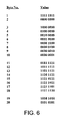
- FIG. 6 illustrates an exemplary bit pattern
- improved techniques are described for providing continuity check operations to ensure circuit integrity for communications over a packet-switched network.
- the techniques involve the exchange of a known pattern of bits during call set up processes rather than sending and detecting tones.
- the techniques can be used to test the integrity of the packet circuit and the adapters at either end of the circuit.
- a continuous call path can be established starting with a narrowband Signaling System 7 (SS7) ISDN user part (ISUP) call that originates, for example, in a Public Switched Telephone Network (PSTN) 102 A.
- SS7 narrowband Signaling System 7
- ISUP ISDN user part
- PSTN Public Switched Telephone Network
- the path can be established using a virtual circuit over an ATM network 101 and completes on the terminating side in a narrowband circuit-switched SS7 ISUP call to the terminating subscriber through another circuit switched network 102 B.
- a control mechanism interacts with the circuit-switched and packet-switched networks to correlate SS7 and ATM connections to establish a single continuous information path.
- a large number of individual telephone circuits, such as DS0 circuits, that are to be connected to the packet network 101 can be carried, for example, on fiber optic carriers 105 using time-division multiplexing (TDM) according to the Telcordia Synchronous Optical Network (SONET) standards.
- TDM time-division multiplexing
- SONET Telcordia Synchronous Optical Network
- the media gateways 100 A, 100 B adapt the TDM telephone line signals to packet-based signals and vice-versa.
- the TDM telephone signals are circuit-switched, in other words, the bit stream can be divided temporally into individual DS0 circuits.
- the bit stream in packet-based signals, can be divided according to the destination address of each packet.
- Each gateway 100 A, 100 B can separate incoming TDM signals into individual DS0 signal streams.
- each gateway such as the gateway 10 A, includes a TDM switching matrix 117 that provides full switching capabilities.
- the switching matrices 117 permit the DS0 circuits to be interconnected flexibly with narrowband channels appearing on the gateways. Echo cancellation and other digital signal processing functions can be performed in a digital signal processing portion 118 of each gateway.
- the signal processing portion 118 includes a pattern generator 122 and a pattern detector 124 for generating and detecting specified patterns of bits, respectively.
- the pattern generator 122 and pattern detector 124 can be implemented, for example, using microprocessors, digital signal processors, or custom application specific integrated circuits (ASICs).
- the DS0 signal streams are adapted by an ATM adaptation layer 120 into ATM cells. Each cell is inserted through the ATM ports 21 into an ATM cell stream 135 that traverses an ATM network 101 .
- the gateways include a control section 119 that controls overall operation of the gateway.
- the gateways 100 A, 100 B are implemented as Salix 7720. Class-Independent Switches available from Tellabs Operations, Inc.
- each gateway 100 A, 100 B is connected to a respective ATM end point switch 115 .
- the connection between a gateway and an ATM end point switch 115 and the connection between the ATM end point switch and the ATM network 101 are user-network interfaces (UNIs).
- UNIs user-network interfaces
- Within the ATM network 101 there are a number of ATM switches 110 which are interconnected by network-node interfaces (NNIs).
- NNIs network-node interfaces
- a call control network 126 which forms part of an existing telephone system, runs parallel to the voice network.
- the call control network 126 primarily controls telephone switching equipment to connect the originating and terminating ends of a telephone call using SS7 messages.
- a call controller 120 A, 120 B is coupled to each gateway 100 A, 100 B and provides an interface between the gateway and the call control network 126 .
- the exchange of call control signals allows the gateways 100 A, 100 B to establish a connection through the ATM network 101 to enable the transmission of narrowband traffic between the end points.
- a user at the originating end dials 210 a telephone number.
- a connection is established through an originating TDM circuit switch in the circuit switched network 102 A, and the call controller 120 A at the originating end receives 215 an SS7 initial address message (IAM) 150 .
- the call controller 120 A routes 220 the call, in other words, it identifies a call controller 120 B associated with a terminating DS0 circuit in the circuit switched network 102 B.
- the call controller 120 A also determines 225 whether a continuity check operation is to be performed as part of the call set up.
- a trade-off exists between the desire to perform a continuity check during each call set up and the extra time and overhead associated with performing continuity checks. As a result, typically only a percentage of the call set-ups will include a continuity check operation. In one implementation, approximately 5–10% of call set-ups would include a continuity check operation.
- the call controller 120 A determines that a continuity check operation is to be performed
- the call controller sends 230 a connection control message (CreateConn) 152 to the originating gateway 100 A to initiate a connection through the ATM network 101 .
- the CreateConn message 152 includes an indication that a sending-side continuity check operation is requested.
- the gateway 100 A reserves 235 resources for the call and makes the pattern generator 122 and pattern detector 124 available. Connections are set up between the adaptation layer 120 and the pattern generator 122 as well as the pattern detector 124 .
- the pattern generator 122 repeatedly generates 240 a specified bit pattern, and the detector 124 monitors 245 the incoming packet stream (if any) for the same bit pattern.
- the pattern generator 122 is programmed to generate a bit pattern such that both binary values in each possible bit position in the packet can be checked.
- the pattern generator 122 can generate a sequence of two complementary 8-bit values.
- Other bit patterns can be generated to allow various types of potential failures to be detected and isolated.
- the pattern generator 122 is programmed to generate a bit pattern comprising a sequence of 256 values, in other words, a sequence of all possible 8-bit values. More generally, the pattern generator 122 can be programmed to generate a sequence of all possible n-bit values, where n is the number of bits in each byte.
- FIG. 6 Another exemplary pattern is illustrated in FIG. 6 and includes twenty 8-bit values.
- a first byte includes only “1”s, whereas a second byte includes only “0”s.
- the third through tenth bytes include a single binary “1” with adjacent bytes differing by shifting the binary “1” value from one bit position to an adjacent bit position.
- the eleventh through the eighteenth bytes include a single binary “0” with adjacent bytes differing by shifting the binary “0” value from one bit position to an adjacent bit position.
- the nineteenth byte includes an alternating pattern of “1”s and “0”s.
- the twentieth byte includes the inverse pattern of the nineteenth byte.
- Other bit patterns may be used depending on the specific errors to be detected. Known error detection/correction techniques may be useful in selecting an appropriate bit pattern for a given application.
- the gateway 100 A After making the pattern generator 122 and detector 124 available, the gateway 100 A returns 250 an acknowledgement message (CreateAck) 154 that includes a connection descriptor.
- the connection descriptor includes an ATM address for the gateway 100 A as well as information that uniquely identifies the call.
- the information that uniquely identifies the call can identify a connection-related resource such as the narrowband circuit (e.g., DS0 circuit) handling the call on the originating side.
- the narrowband circuit e.g., DS0 circuit
- the call controller 120 A sends 255 an IAM message 156 to the terminating call controller 120 B.
- the message 156 includes the information contained in the connection descriptor as well as an indication that the continuity check operation is to be performed.
- the terminating call controller 120 B routes 260 the call. In other words, the terminating call controller 120 B selects a TDM circuit on a particular gateway, such as the gateway 100 B, to handle the call.
- the call controller 120 B then sends 265 a connection control message (CreateConn) 158 to the terminating gateway 100 B.
- the CreateConn message 158 also includes the information contained in the connection descriptor.
- the message 158 includes an indication that the receiving-side of a continuity check operation is being requested.
- the terminating gateway 100 B establishes 270 a packet domain connection 126 with the originating gateway 100 A through the packet network 101 , as shown in FIG. 5 .
- the information that uniquely identifies the call is forwarded through the packet switches 110 , 115 until it is received by the originating gateway 10 A. That allows the originating gateway 100 A to associate the packet-domain connection with the TDM-domain connection for the call.
- the gateways 100 A, 100 B and ATM switches 110 , 115 negotiate the ATM routing headers that will be used between hops along the packet-domain connection.
- the gateway 100 B also sets up 275 a continuity check loop between the incoming and outgoing packet streams 128 , 130 associated with the packet network connection.
- FIG. 5 shows the loopback provided in the TDM-domain of the gateway 100 B. More generally, however, the loopback can be provided in either the TDM-domain or the packet-domain depending on the type of failures the continuity check is intended to detect.
- a control message (CreateAck) 178 is sent 280 by the terminating gateway 100 B to the terminating call controller 120 B to acknowledge that the packet-domain connection has been established for the call and that the continuity check loop has been set up.
- the bit pattern appears as successive TDM samples in the TDM domain, when the loopback is provided in the TDM domain, and appears within the cell stream in the ATM domain.
- the pattern detector 124 monitors 245 the incoming bit patterns and determines 285 ( FIG. 3A ) whether the incoming pattern matches the bit pattern that was generated by the generator 122 . If the packet connection is properly established and if the adaptation functions in the gateways 10 A, 100 B are operating properly, the specified bit pattern will be detected by the detector 124 after traversing the packet connection 116 and the continuity check loop.
- the pattern detector 122 can include a software or hardware timer 132 that provides a timeout function. If the pattern detector 124 does not detect the generated pattern within the time set by the timer 132 , the continuity check fails. In that case, the gateway 100 A signals 165 the call controller 120 A or a management system (not shown) to inform 290 it of the failure. The results of the continuity check operation can be used to determine the cause of the failure.
- the continuity check is successful.
- the gateway 100 A disconnects 295 the pattern generator 122 to allow a purge operation to be performed so that the pattern of bits is not forwarded to the TDM circuit handling the call. Once the detector 124 no longer detects the pattern, the adaptation layer 116 in the originating gateway 100 A is connected 300 to the DS0 circuit that is handling the call.
- the gateway 100 A also notifies 305 its call controller 120 A that the pattern has been detected.
- the originating call controller 120 A sends 310 an SS7 message to the terminating call controller 120 B informing it of the successful continuity check.
- the call controller 120 B instructs the terminating gateway 100 B to disconnect 315 the loopback between the incoming and outgoing packet streams.
- the terminating gateway 100 B is then reconfigured 320 to continue processing the call.
- Continuity check packets also can be used as a coarse determination of the Cell Delay Variation in the packet network. In that case, the pattern of bits should be sent over at least several cells.
- continuity check operations can be used in systems employing “robbed” bit supervisory signaling as well as clear channel operation.
- continuity check packets are used in a system employing “robbed” bit supervisory signaling
- the fact that the low order bits of some frames are used for the supervisory signaling should be accounted for.
- the bits that are used for supervisory signaling can simply be ignored for the purpose of the continuity checks.
- both the originating and terminating gateways 100 A, 100 B may share a common call controller, such as the call controller 120 A. In that case, a technique similar to that discussed above can be used with a single call controller performing the functions of both call controllers 120 A, 120 B.
- the call controller 120 A routes the call after receiving the IAM message 150 , it selects the terminating TDM circuit switch and the corresponding terminating gateway 100 B to handle the call. Also, when a single call controller 120 A is involved, the IAM message 156 need not be used.
- circuit-switched traffic can be routed over other packet-domain networks, such as frame relay, Ethernet and Internet Protocol (IP) networks, as well.
- packet-domain networks such as frame relay, Ethernet and Internet Protocol (IP) networks
- Continuity check operations based on a pattern of digital bits are not limited to systems under the control of SS7 signaling.
- continuity checks can be performed independently of call set-up processes.
- the pattern generator 122 can continuously generate a pattern over an existing packet connection.
- the pattern detector 124 monitors the return signals and checks whether the specified pattern is detected. The output of the pattern detector 124 then can be read on demand. Such testing can be used, for example, as part of a maintenance program to determine how often failures occur on a particular packet connection and its associated gateways.
- a gateway has multiple adapters for handling conversions between packet-based and TDM-based bearers
- separate pattern generators 122 and pattern detectors 124 can be provided for each adapter.
- the specified pattern can be broadcast over the multiple ATM channels and/or connections.
- the timer 132 can be incorporated into the call controller 120 A. In that case, the call controller 120 A would determine that the continuity check had failed if the gateway 100 A did not notify it that the continuity check was successful within the specified time. Alternatively, the call controller 120 A can be programmed to query the gateway 100 A regarding the success of the continuity check if the gateway has not provided an indication prior to the specified time elapsing. The success or failure of the continuity check would then be determined based on the gateway's response.
- Various features of the system can be implemented in hardware, software, or a combination of hardware and software.
- some aspects of the system can be implemented in computer programs executing on programmable computers.
- Each program can be implemented in a high level procedural or object-oriented programming language to communicate with a computer system.
- each such computer program can be stored on a storage medium, such as read-only-memory (ROM) readable by a general or special purpose programmable computer, for configuring and operating the computer when the storage medium is read by the computer to perform the functions described above.
- ROM read-only-memory
Abstract
Description
Claims (18)
Priority Applications (2)
| Application Number | Priority Date | Filing Date | Title |
|---|---|---|---|
| US09/632,393 US7054273B1 (en) | 1999-08-06 | 2000-08-04 | Circuit integrity in a packet-switched network |
| US11/336,535 US7539148B2 (en) | 1999-08-06 | 2006-01-20 | Circuit integrity in a packet-switched network |
Applications Claiming Priority (2)
| Application Number | Priority Date | Filing Date | Title |
|---|---|---|---|
| US14746299P | 1999-08-06 | 1999-08-06 | |
| US09/632,393 US7054273B1 (en) | 1999-08-06 | 2000-08-04 | Circuit integrity in a packet-switched network |
Related Child Applications (1)
| Application Number | Title | Priority Date | Filing Date |
|---|---|---|---|
| US11/336,535 Continuation US7539148B2 (en) | 1999-08-06 | 2006-01-20 | Circuit integrity in a packet-switched network |
Publications (1)
| Publication Number | Publication Date |
|---|---|
| US7054273B1 true US7054273B1 (en) | 2006-05-30 |
Family
ID=36462698
Family Applications (2)
| Application Number | Title | Priority Date | Filing Date |
|---|---|---|---|
| US09/632,393 Expired - Fee Related US7054273B1 (en) | 1999-08-06 | 2000-08-04 | Circuit integrity in a packet-switched network |
| US11/336,535 Expired - Fee Related US7539148B2 (en) | 1999-08-06 | 2006-01-20 | Circuit integrity in a packet-switched network |
Family Applications After (1)
| Application Number | Title | Priority Date | Filing Date |
|---|---|---|---|
| US11/336,535 Expired - Fee Related US7539148B2 (en) | 1999-08-06 | 2006-01-20 | Circuit integrity in a packet-switched network |
Country Status (1)
| Country | Link |
|---|---|
| US (2) | US7054273B1 (en) |
Cited By (10)
| Publication number | Priority date | Publication date | Assignee | Title |
|---|---|---|---|---|
| US20030099227A1 (en) * | 2001-11-24 | 2003-05-29 | Lg Electronics Inc. | Call control method between a packet network and PSTNs in the next generation network |
| US20030231623A1 (en) * | 2002-06-17 | 2003-12-18 | Lg Electronics Inc. | Routing system in the next generation open network and method of controlling the routing system |
| US20040081116A1 (en) * | 2002-09-09 | 2004-04-29 | Clay John J. | Communication system with a packet-handling digital cross-connect system |
| US20040151178A1 (en) * | 2001-07-24 | 2004-08-05 | Klaus Hoffmann | Method for testing a bearer channel connection in a telecommunication system |
| US20040246968A1 (en) * | 2001-10-12 | 2004-12-09 | Andreas Knaebchen | Method for establishing a communication link between subscriber stations of a switching system which comprises two communication networks |
| US20060174006A1 (en) * | 2002-07-25 | 2006-08-03 | Magnus Hallenstal | End to end test between gateways in an ip network |
| US20060268680A1 (en) * | 2005-05-25 | 2006-11-30 | Alcatel | Communication network connection failure protection methods and systems |
| WO2008004196A2 (en) * | 2006-07-04 | 2008-01-10 | Vastech Sa (Pty) Limited | Gateway for use in an electronic communications recording system |
| WO2008028415A1 (en) * | 2006-08-29 | 2008-03-13 | Huawei Technologies Co., Ltd. | A method, originating office, target office and system fof continuity check |
| US20090154364A1 (en) * | 2007-12-17 | 2009-06-18 | Gridpoint Systems Inc. | Carrier ethernet with fault notification |
Families Citing this family (5)
| Publication number | Priority date | Publication date | Assignee | Title |
|---|---|---|---|---|
| US7489640B2 (en) * | 2003-09-30 | 2009-02-10 | Agere Systems Inc. | Processor with continuity check cache |
| WO2010133750A1 (en) * | 2009-05-18 | 2010-11-25 | Nokia Corporation | Systems, methods, and apparatuses for facilitating a circuit switched connection |
| WO2010142312A1 (en) * | 2009-06-12 | 2010-12-16 | Telefonaktiebolaget L M Ericsson (Publ) | Monitoring of delay in packet-switched networks |
| EP2437194A1 (en) * | 2010-10-01 | 2012-04-04 | Nagravision S.A. | System and method to prevent manipulation of video data transmitted on an HDMI link. |
| JP7006533B2 (en) * | 2018-08-09 | 2022-01-24 | 日本電信電話株式会社 | Media gateway device and media path setting method |
Citations (13)
| Publication number | Priority date | Publication date | Assignee | Title |
|---|---|---|---|---|
| US5251204A (en) * | 1990-09-19 | 1993-10-05 | Fujitsu Limited | Transmission test system in a broadband ISDN |
| US5313453A (en) * | 1991-03-20 | 1994-05-17 | Fujitsu Limited | Apparatus for testing ATM channels |
| WO1995017789A1 (en) | 1993-12-20 | 1995-06-29 | At & T Corp. | Atm networks for narrow band communications |
| US5555261A (en) * | 1994-02-07 | 1996-09-10 | Fujitsu Limited | Interface device between a network and an exchange for assembling fixed-length cell and transmitting the same |
| WO1998023053A1 (en) | 1996-11-22 | 1998-05-28 | Sprint Communications Company, L.P. | Telecommunications system |
| US5825780A (en) | 1994-05-05 | 1998-10-20 | Sprint Communications Co.L.P. | Method, system and apparatus for telecommunications control |
| US5991301A (en) | 1994-05-05 | 1999-11-23 | Sprint Communications Co. L.P. | Broadband telecommunications system |
| US6023474A (en) | 1996-11-22 | 2000-02-08 | Sprint Communications C.O.L.P. | Broadband telecommunications system interface |
| US6067299A (en) | 1997-04-16 | 2000-05-23 | Sprint Communications Company, L.P. | Communications system for providing ATM connections and echo cancellation |
| US6075784A (en) | 1998-06-08 | 2000-06-13 | Jetstream Communications, Inc. | System and method for communicating voice and data over a local packet network |
| US6272137B1 (en) * | 1997-03-21 | 2001-08-07 | Oki Electric Industry Co., Ltd. | ATM transmission system with subsystems interconnected through reduced number of signal lines |
| US6470019B1 (en) * | 1998-02-20 | 2002-10-22 | Sprint Communications Company L.P. | System and method for treating a call for call processing |
| US6519257B1 (en) * | 1996-07-05 | 2003-02-11 | Nortel Networks Limited | ATM telecommunications systems and method for routing narrow band traffic |
Family Cites Families (4)
| Publication number | Priority date | Publication date | Assignee | Title |
|---|---|---|---|---|
| JP2892180B2 (en) * | 1991-04-30 | 1999-05-17 | 富士通株式会社 | Monitoring system for ATM cross-connect equipment |
| US5617417A (en) * | 1994-09-07 | 1997-04-01 | Stratacom, Inc. | Asynchronous transfer mode communication in inverse multiplexing over multiple communication links |
| EP1416678A3 (en) * | 1997-05-13 | 2004-05-26 | Matsushita Electric Industrial Co., Ltd. | Packet transmitter |
| US5878032A (en) * | 1997-11-07 | 1999-03-02 | Northern Telecom Limited | Delay monitoring of telecommunication networks |
-
2000
- 2000-08-04 US US09/632,393 patent/US7054273B1/en not_active Expired - Fee Related
-
2006
- 2006-01-20 US US11/336,535 patent/US7539148B2/en not_active Expired - Fee Related
Patent Citations (14)
| Publication number | Priority date | Publication date | Assignee | Title |
|---|---|---|---|---|
| US5251204A (en) * | 1990-09-19 | 1993-10-05 | Fujitsu Limited | Transmission test system in a broadband ISDN |
| US5313453A (en) * | 1991-03-20 | 1994-05-17 | Fujitsu Limited | Apparatus for testing ATM channels |
| WO1995017789A1 (en) | 1993-12-20 | 1995-06-29 | At & T Corp. | Atm networks for narrow band communications |
| US5555261A (en) * | 1994-02-07 | 1996-09-10 | Fujitsu Limited | Interface device between a network and an exchange for assembling fixed-length cell and transmitting the same |
| US5991301A (en) | 1994-05-05 | 1999-11-23 | Sprint Communications Co. L.P. | Broadband telecommunications system |
| US5825780A (en) | 1994-05-05 | 1998-10-20 | Sprint Communications Co.L.P. | Method, system and apparatus for telecommunications control |
| US6031840A (en) | 1995-12-07 | 2000-02-29 | Sprint Communications Co. L.P. | Telecommunications system |
| US6519257B1 (en) * | 1996-07-05 | 2003-02-11 | Nortel Networks Limited | ATM telecommunications systems and method for routing narrow band traffic |
| WO1998023053A1 (en) | 1996-11-22 | 1998-05-28 | Sprint Communications Company, L.P. | Telecommunications system |
| US6023474A (en) | 1996-11-22 | 2000-02-08 | Sprint Communications C.O.L.P. | Broadband telecommunications system interface |
| US6272137B1 (en) * | 1997-03-21 | 2001-08-07 | Oki Electric Industry Co., Ltd. | ATM transmission system with subsystems interconnected through reduced number of signal lines |
| US6067299A (en) | 1997-04-16 | 2000-05-23 | Sprint Communications Company, L.P. | Communications system for providing ATM connections and echo cancellation |
| US6470019B1 (en) * | 1998-02-20 | 2002-10-22 | Sprint Communications Company L.P. | System and method for treating a call for call processing |
| US6075784A (en) | 1998-06-08 | 2000-06-13 | Jetstream Communications, Inc. | System and method for communicating voice and data over a local packet network |
Non-Patent Citations (5)
| Title |
|---|
| A Generic ATM Trunking architecture for integration of PSTN/ISDN narrowband services:, ATM Forun/99-0048, Jan. 18, 1999. |
| Committee T1S1 Contribution 9S101470, TitledSignalling Requirements for the support of narrow band services via broadband transport technologies (posted Jun. 20, 1999 at the T1S1 web site). * |
| IITU-T, Recommendation I.610, B-ISDN Operation and Maintenance Principles and Functions (Nov. 1995). * |
| ITU-T, Q. Supp 16, TRQ2140, Signalling requirements for the support of narrowband services via broadband transport technologies, Dec. 1999. * |
| ITU-T, Recommendation I.732, Functional characteristics of ATM equipment, (Mar. 1996). * |
Cited By (20)
| Publication number | Priority date | Publication date | Assignee | Title |
|---|---|---|---|---|
| US20040151178A1 (en) * | 2001-07-24 | 2004-08-05 | Klaus Hoffmann | Method for testing a bearer channel connection in a telecommunication system |
| US20040246968A1 (en) * | 2001-10-12 | 2004-12-09 | Andreas Knaebchen | Method for establishing a communication link between subscriber stations of a switching system which comprises two communication networks |
| US7447217B2 (en) * | 2001-10-12 | 2008-11-04 | Siemens Aktiengellschaft | Method for establishing a communication link between subscriber stations of a switching system which comprises two communication networks |
| US20030099227A1 (en) * | 2001-11-24 | 2003-05-29 | Lg Electronics Inc. | Call control method between a packet network and PSTNs in the next generation network |
| US7170888B2 (en) * | 2001-11-24 | 2007-01-30 | Lg-Nortel Co., Ltd. | Call control method between a packet network and PSTNs in the next generation network |
| US20030231623A1 (en) * | 2002-06-17 | 2003-12-18 | Lg Electronics Inc. | Routing system in the next generation open network and method of controlling the routing system |
| US20060174006A1 (en) * | 2002-07-25 | 2006-08-03 | Magnus Hallenstal | End to end test between gateways in an ip network |
| US7644178B2 (en) * | 2002-07-25 | 2010-01-05 | Telefonaktiebolaget L M Ericsson (Publ) | End to end test between gateways in a IP network |
| US20040081116A1 (en) * | 2002-09-09 | 2004-04-29 | Clay John J. | Communication system with a packet-handling digital cross-connect system |
| US8730814B2 (en) * | 2005-05-25 | 2014-05-20 | Alcatel Lucent | Communication network connection failure protection methods and systems |
| US20060268680A1 (en) * | 2005-05-25 | 2006-11-30 | Alcatel | Communication network connection failure protection methods and systems |
| WO2008004196A3 (en) * | 2006-07-04 | 2008-03-13 | Vastech Sa Pty Ltd | Gateway for use in an electronic communications recording system |
| WO2008004196A2 (en) * | 2006-07-04 | 2008-01-10 | Vastech Sa (Pty) Limited | Gateway for use in an electronic communications recording system |
| AU2007270728B2 (en) * | 2006-07-04 | 2011-07-07 | Vastech Sa (Pty) Limited | Gateway for use in an electronic communications recording system |
| US20090304012A1 (en) * | 2006-07-04 | 2009-12-10 | Marthinus Casper Ackerman | Gateway for use in an electronic communications recording system |
| US8036236B2 (en) | 2006-07-04 | 2011-10-11 | Vastech Sa (Pty) Limited | Gateway for use in an electronic communications recording system |
| WO2008028415A1 (en) * | 2006-08-29 | 2008-03-13 | Huawei Technologies Co., Ltd. | A method, originating office, target office and system fof continuity check |
| CN1913548B (en) * | 2006-08-29 | 2010-04-14 | 华为技术有限公司 | Connection checking method, calling bureau and connection checking system |
| US7839795B2 (en) * | 2007-12-17 | 2010-11-23 | Ciena Corporation | Carrier Ethernet with fault notification |
| US20090154364A1 (en) * | 2007-12-17 | 2009-06-18 | Gridpoint Systems Inc. | Carrier ethernet with fault notification |
Also Published As
| Publication number | Publication date |
|---|---|
| US20060120295A1 (en) | 2006-06-08 |
| US7539148B2 (en) | 2009-05-26 |
Similar Documents
| Publication | Publication Date | Title |
|---|---|---|
| US7539148B2 (en) | Circuit integrity in a packet-switched network | |
| US6449259B1 (en) | Communication controller | |
| KR100540408B1 (en) | Next hop loopback | |
| US6222820B1 (en) | Method of VCC/VPC redundancy for asynchronous transfer mode networks | |
| US7778163B2 (en) | System and method for detecting failures and re-routing connections in a communication network | |
| US7417977B2 (en) | Apparatus and method for a telephony gateway | |
| CA2124418C (en) | Method and circuit arrangement for the transmission of message packets according to the asynchronous transfer mode in a communication network | |
| KR20010013967A (en) | Segment performance monitoring | |
| JP3200438B2 (en) | Data packet identification | |
| US6873599B1 (en) | Apparatus and method for error isolation in hybrid communications systems | |
| US6195346B1 (en) | Method and system for processing an HDLC message | |
| US6233221B1 (en) | System and method for a ring network with virtual path connections | |
| Turner | Design of an integrated services packet network | |
| US7016355B1 (en) | Determination of the propagation delay in a packet switched network | |
| JPH08340337A (en) | Atm transmitter | |
| US6172973B1 (en) | Apparatus and method for reducing delay for voice over ATM using co-located switches | |
| US6172977B1 (en) | ATM direct access line system | |
| US6882626B1 (en) | System and method for automated switching of data traffic in a packet network | |
| WO2001011853A2 (en) | Circuit integrity in a packet-switched network | |
| CA2313602C (en) | Virtual transport server in a telecommunication network | |
| EP0878080A1 (en) | Interworking function | |
| US6081535A (en) | STM-16 network-node interface in an ATM switch and the fault diagnosing method thereof | |
| EP1001649A2 (en) | Channel integrity in a voice-on-ATM network | |
| US20010053125A1 (en) | Fail-over circuit for voice-enabled switch | |
| CA2233014C (en) | A communication controller |
Legal Events
| Date | Code | Title | Description |
|---|---|---|---|
| AS | Assignment |
Owner name: TELLABS OPERATIONS, INC., ILLINOIS Free format text: ASSIGNMENT OF ASSIGNORS INTEREST;ASSIGNORS:SCHOLTENS, DALE A.;WELLS, DAVID;REEL/FRAME:011414/0342;SIGNING DATES FROM 20001026 TO 20001201 |
|
| FEPP | Fee payment procedure |
Free format text: PAYOR NUMBER ASSIGNED (ORIGINAL EVENT CODE: ASPN); ENTITY STATUS OF PATENT OWNER: LARGE ENTITY |
|
| AS | Assignment |
Owner name: TELLABS OPERATIONS, INC., ILLINOIS Free format text: ASSIGNMENT OF ASSIGNORS INTEREST;ASSIGNORS:WELLS, DAVID;SCHOLTENS, DALE A.;REEL/FRAME:022574/0736;SIGNING DATES FROM 20090327 TO 20090406 |
|
| FPAY | Fee payment |
Year of fee payment: 4 |
|
| FEPP | Fee payment procedure |
Free format text: PAYOR NUMBER ASSIGNED (ORIGINAL EVENT CODE: ASPN); ENTITY STATUS OF PATENT OWNER: LARGE ENTITY Free format text: PAYER NUMBER DE-ASSIGNED (ORIGINAL EVENT CODE: RMPN); ENTITY STATUS OF PATENT OWNER: LARGE ENTITY |
|
| FPAY | Fee payment |
Year of fee payment: 8 |
|
| FEPP | Fee payment procedure |
Free format text: PAYER NUMBER DE-ASSIGNED (ORIGINAL EVENT CODE: RMPN); ENTITY STATUS OF PATENT OWNER: LARGE ENTITY Free format text: PAYOR NUMBER ASSIGNED (ORIGINAL EVENT CODE: ASPN); ENTITY STATUS OF PATENT OWNER: LARGE ENTITY |
|
| AS | Assignment |
Owner name: CERBERUS BUSINESS FINANCE, LLC, AS COLLATERAL AGEN Free format text: SECURITY AGREEMENT;ASSIGNORS:TELLABS OPERATIONS, INC.;TELLABS RESTON, LLC (FORMERLY KNOWN AS TELLABS RESTON, INC.);WICHORUS, LLC (FORMERLY KNOWN AS WICHORUS, INC.);REEL/FRAME:031768/0155 Effective date: 20131203 |
|
| AS | Assignment |
Owner name: TELECOM HOLDING PARENT LLC, CALIFORNIA Free format text: ASSIGNMENT FOR SECURITY - - PATENTS;ASSIGNORS:CORIANT OPERATIONS, INC.;TELLABS RESTON, LLC (FORMERLY KNOWN AS TELLABS RESTON, INC.);WICHORUS, LLC (FORMERLY KNOWN AS WICHORUS, INC.);REEL/FRAME:034484/0740 Effective date: 20141126 |
|
| AS | Assignment |
Owner name: TELECOM HOLDING PARENT LLC, CALIFORNIA Free format text: CORRECTIVE ASSIGNMENT TO CORRECT THE REMOVE APPLICATION NUMBER 10/075,623 PREVIOUSLY RECORDED AT REEL: 034484 FRAME: 0740. ASSIGNOR(S) HEREBY CONFIRMS THE ASSIGNMENT FOR SECURITY --- PATENTS;ASSIGNORS:CORIANT OPERATIONS, INC.;TELLABS RESTON, LLC (FORMERLY KNOWN AS TELLABS RESTON, INC.);WICHORUS, LLC (FORMERLY KNOWN AS WICHORUS, INC.);REEL/FRAME:042980/0834 Effective date: 20141126 |
|
| FEPP | Fee payment procedure |
Free format text: MAINTENANCE FEE REMINDER MAILED (ORIGINAL EVENT CODE: REM.) |
|
| LAPS | Lapse for failure to pay maintenance fees |
Free format text: PATENT EXPIRED FOR FAILURE TO PAY MAINTENANCE FEES (ORIGINAL EVENT CODE: EXP.) |
|
| STCH | Information on status: patent discontinuation |
Free format text: PATENT EXPIRED DUE TO NONPAYMENT OF MAINTENANCE FEES UNDER 37 CFR 1.362 |
|
| FP | Lapsed due to failure to pay maintenance fee |
Effective date: 20180530 |