US7026774B2 - Rotor position determination device of rotating electric machine and control device of rotating electric machine - Google Patents
Rotor position determination device of rotating electric machine and control device of rotating electric machine Download PDFInfo
- Publication number
- US7026774B2 US7026774B2 US11/188,674 US18867405A US7026774B2 US 7026774 B2 US7026774 B2 US 7026774B2 US 18867405 A US18867405 A US 18867405A US 7026774 B2 US7026774 B2 US 7026774B2
- Authority
- US
- United States
- Prior art keywords
- rotor
- phase
- armature coils
- electric machine
- rotating electric
- Prior art date
- Legal status (The legal status is an assumption and is not a legal conclusion. Google has not performed a legal analysis and makes no representation as to the accuracy of the status listed.)
- Active
Links
Images


Classifications
-
- H—ELECTRICITY
- H02—GENERATION; CONVERSION OR DISTRIBUTION OF ELECTRIC POWER
- H02P—CONTROL OR REGULATION OF ELECTRIC MOTORS, ELECTRIC GENERATORS OR DYNAMO-ELECTRIC CONVERTERS; CONTROLLING TRANSFORMERS, REACTORS OR CHOKE COILS
- H02P6/00—Arrangements for controlling synchronous motors or other dynamo-electric motors using electronic commutation dependent on the rotor position; Electronic commutators therefor
- H02P6/14—Electronic commutators
- H02P6/16—Circuit arrangements for detecting position
- H02P6/18—Circuit arrangements for detecting position without separate position detecting elements
- H02P6/185—Circuit arrangements for detecting position without separate position detecting elements using inductance sensing, e.g. pulse excitation
Definitions
- the present invention relates to a rotor position determination device for determining a position of a rotor of a rotating electric machine, and a control device for controlling to operate the rotating electric machine as a motor by using the rotor position determination device.
- a magneto generator comprised of a rotor that produces a magnetic field by mounting a permanent magnet to a rotor yoke, and a stator having polyphase armature coils
- a rotating electric machine comprised of a rotor having a magnetic field and a stator having polyphase armature coils operates as a generator when the rotor is externally driven.
- Such a rotating electric machine operates as a motor when a drive current is passed through the armature coils while an excitation phase is switched according to a relative positional relationship between the magnetic field of the rotor and the armature coils.
- an inverter circuit is provided between a battery and armature coils of a rotating electric machine comprised of a rotor having a magnetic field and a stator having polyphase armature coils, and a combination of switch elements of the inverter circuit that need to be turned on at each position of the rotor in order to rotate the rotor in a predetermined direction is regarded as a switch pattern, and the inverter circuit is controlled while the switch pattern is switched according to the position of the rotor (a positional relationship between the magnetic field of the rotor and the armature coil of each phase), thereby allowing the rotating electric machine to be operated as a motor.
- the rotating electric machine comprised of the rotor having the magnetic field and the stator having the armature coils may be operated as both the generator and the motor, and as disclosed in Japanese Patent Application Laid-Open Publication No. 2004-80931, it has been considered that a rotating electric machine mounted in an internal combustion engine is operated as a motor at the start of the engine to start the internal combustion engine, and after the engine is started, the rotating electric machine is operated as a motor to charge a battery by using output of the rotating electric machine.
- a rotating electric machine is referred to as a starter generator.
- a polarity of a magnetic pole of a rotor is detected by a magnetic sensor comprised of a Hall element to detect a position of the rotor where a switch pattern of an inverter circuit is switched.
- a resolver has been also known as a sensor for detecting a position where a switch pattern is switched.
- the magnetic field of the rotor is produced by a permanent magnet, and thus the magnetic field cannot be controlled by a method similar to that for a generator having magnetic field winding to control an output of the generator.
- the generating device is comprised so as to apply the AC control voltage having the same frequency as an induced voltage of the armature coil to the armature coil from the voltage storage means such as the battery or the capacitor provided on the load side via the inverter circuit, wherein a phase of the AC control voltage is changed to change a magnetic flux linking the armature coil and change an output characteristic of a magneto generator.
- the AC control voltage having the same frequency as the induced voltage of the armature coil is applied to the armature coil to change a phase angle of the AC control voltage to a delayed side relative to a phase of a no-load induced voltage of the armature coil, thereby generally increasing an output of the generator.
- the phase angle of the AC control voltage is changed to an advanced side, thereby reducing the output of the generator.
- the phase angle of the AC control voltage relative to the phase of the no-load induced voltage of the armature coil is referred to as a “control angle”.
- the control angle is changed to the delayed side or the advanced side to allow control for matching the output of the generator with the target value.
- drive control means controlling the output of the generator while driving the generator from the load side.
- a position of a rotor (a relative positional relationship between a magnetic field and an armature coil of each phase of a stator) needs to be detected in order to determine the phase angle of the AC control voltage.
- the position of the rotor can be detected by using a Hall element.
- the position of the rotor is detected by using a signal generating device that detects an edge of a reluctor to generate a pulse signal when a rotational angle position of the rotor matches a predetermined position.
- a resistor circuit comprised of three resistors star-connected is connected in parallel with three-phase armature coils star-connected, the sum of the reverse induced voltages of the three-phase armature coils is detected from a potential difference between a neutral point of the armature coils and a neutral point of the resistor circuit, and the position of the rotor is detected based on a change in the sum of the reverse induced voltages.
- the Hall element has low heat resistance, and thus if the Hall element is used as a sensor for detecting the position of the rotor where a switch pattern of an inverter circuit for controlling supply of a drive current to armature coils is switched when a rotating electric machine is used in high temperature environments such as when a rotating electric machine comprised of a magnet rotor mounted to a crankshaft of an internal combustion engine and a stator having polyphase armature coils is operated as a brushless motor to start the engine, the Hall element may be damaged by heat from its surroundings.
- resolver When a resolver is used as a sensor for detecting the position of the rotor where the switch pattern of the inverter circuit is switched, the resolver itself is expensive, and a detection circuit for detecting a phase difference between an excitation voltage and an output voltage is required, which increases costs of a rotating electric machine.
- the senor As disclosed in Japanese Patent Application Laid-Open Publication No. 2004-173482, if the position of the rotor is detected by using the signal generating device that detects the edge of the reluctor to generate the pulse signal, the sensor having low heat resistance need not be used. However, the signal generating device that detects the edge of the reluctor to generate the pulse does not generate an output without rotation of the rotating electric machine, and thus the method using such a signal generating device cannot be used for detecting the position of the rotor at the start of the rotating electric machine when operated as the brushless motor.
- the method for detecting the position of the rotor from the changes in the reverse induced voltages of the armature coils can be applied only when the rotating electric machine is rotated and the armature coils generate the reverse induced voltages, and thus cannot be used as the method for detecting the position of the rotor at the start of the rotating electric machine.
- An object of the present invention is to provide a rotor position determination device of a rotating electric machine capable of detecting a position of a rotor without using a Hall element having low heat resistance or an expensive resolver.
- Another object of the present invention is to provide a control device of a rotating electric machine capable of controlling excitation of armature coils so as to operate the rotating electric machine as a motor without using a Hall element having low heat resistance or an expensive resolver.
- a magnetic field of the rotor may be produced by a permanent magnet mounted to a rotor yoke or by passing an excitation current through an excitation coil wound around a rotor core.
- the rotor position determination device is a device for determining a position of a rotor of a rotating electric machine relative to m-phase (m is an integer equal to or more than 2) armature coils, the rotating electric machine including a stator having the m-phase armature coils, and the rotor having a magnetic field.
- the rotor position determination device includes: transient current energizing means for performing, for each of the m-phase armature coils, a transient current energizing process for temporarily applying a DC voltage to the armature coil of each phase of the stator to pass a transient current through the armature coil of each phase; and rotor position determination means for detecting the transient current passed through each of the m-phase armature coils in the transient current energizing process and determining the position of the rotor relative to the m-phase armature coils from the detected transient currents.
- the transient current energizing means is comprised so as to perform, for each of the m-phase armature coils, a process for temporarily apply a DC voltage between a non-neutral point side terminal of the armature coil of each phase and a grounded potential portion to pass the transient current through the armature coil of each phase.
- the rotor position determination means may be comprised so as to determine the position of the rotor relative to the m-phase armature coils from peak values of the transient currents.
- the rotor position determination means may be comprised so as to determine the position of the rotor relative to the m-phase armature coils from peak values and waveforms of the transient currents.
- a magnetic flux passing through an armature core when no current passes through the armature coils differs according to a relative positional relationship between the position of the magnetic field and the armature coil of each phase (the position of the rotor relative to the armature coil of each phase), and an inductance of the armature coil of each phase differs according to the position of the rotor.
- the transient current passing through the armature coil of each phase of the rotating electric machine when the voltage is applied to the armature coil of each phase differs according to the position of the rotor.
- the process for temporarily applying the DC voltage to the armature coil of each phase of the stator of the rotating electric machine to pass the transient current through the armature coil of each phase is performed for each of the m-phase armature coils, and the peak values or the waveforms of the transient currents passed through the m-phase armature coils are compared to allow determination of the position of the rotor relative to the armature coil of each phase.
- features of the waveforms of the transient currents passed through the m-phase armature coils may be extracted and compared.
- the features of the waveforms of the transient currents may be extracted by the following methods (a) to (c):
- a waveform is determined from a rate of change with time at a leading edge of the transient current.
- a rate of change with time ⁇ i1/ ⁇ t in the first half and a rate of change with time ⁇ i2/ ⁇ t in the second half of a transient current waveform having a time width 2 ⁇ t are calculated to determine whether a difference between the rate of change with time ⁇ i1/ ⁇ t in the first half and the rate of change with time ⁇ i2/ ⁇ t in the second half is a set value or more.
- a control device of a rotating electric machine for controlling supply of a drive current to m-phase armature coils to operate as a motor the rotating electric machine including a stator having m-phase (m is an integer equal to or more than 2) armature coils star-connected so as to have a neutral point, and a rotor having a magnetic field.
- the control device includes: a bridge-type inverter circuit having a DC terminal to which an output of DC power is applied and m number of AC terminals to which m number of non-neutral point side terminals of the m-phase armature coils are connected; a transient current energizing switch provided between a neutral point of the m-phase armature coils and a grounded potential portion; current detection means for detecting a current passing through the transient current energizing switch; and a controller for controlling the inverter circuit and the transient current energizing switch.
- the controller includes: transient current energizing means for controlling switch elements of the inverter circuit and the transient current energizing switch to perform, for each of the m-phase armature coils, a process for temporarily applying a DC voltage between a non-neutral point side terminal of the armature coil of each phase of the stator and the grounded potential portion to pass a transient current through the armature coil of each phase; rotor position determination means for detecting the transient current passed through each of the m-phase armature coils by the transient current energizing means and determining a position of the rotor relative to the m-phase armature coils; switch pattern deciding means for deciding as a switch pattern a combination of switch elements of the inverter circuit that need to be turned on in order to rotate the rotor in a predetermined direction based on the position of the rotor determined by the rotor position determination means; and inverter control means for controlling the inverter circuit so as to turn on
- the rotor position determination means may be comprised so as to determine the position of the rotor relative to the m-phase armature coils from peak values of the transient currents, or comprised so as to determine the position of the rotor relative to the m-phase armature coils from peak values and waveforms of the transient currents.
- the control device of the rotating electric machine includes: a signal generating device that detects an edge of a reluctor to generate a pulse signal when a rotational angle position of the rotor matches a predetermined position; a bridge-type inverter circuit having a DC terminal to which an output of DC power is applied and m number of AC terminals to which m number of non-neutral point side terminals of the m-phase armature coils are connected; a transient current energizing switch provided between a neutral point of the m-phase armature coils and a grounded potential portion; current detection means for detecting a current passing through the transient current energizing switch; and a controller for controlling the inverter circuit and the transient current energizing switch.
- the controller includes: transient current energizing means for controlling switch elements of the inverter circuit and the transient current energizing switch so as to perform, for each of the m-phase armature coils, a process for temporarily applying a DC voltage between a non-neutral point side terminal of the armature coil of each phase of the stator and the grounded potential portion to pass a transient current through the armature coil of each phase; first rotor position determination means for detecting the transient current passed through each of the m-phase armature coils by the transient current energizing means and determining the position of the rotor relative to the m-phase armature coils from the detected transient currents; first switch pattern deciding means for deciding as a switch pattern a combination of switch elements of the inverter circuit that need to be turned on in order to rotate the rotor in a predetermined direction based on the position of the rotor determined by the first rotor position determination means; first inverter control means for
- an excitation current is passed through the armature coil of an excitation phase decided based on the position of the rotor determined from the transient currents passed through the armature coils to start the rotating electric machine.
- the excitation phase is decided based on the position of the rotor determined by using the rotational angle information obtained from the pulse signal output by the signal generating device to excite the armature coil, thereby allowing the rotating electric machine to be rotated similarly to a brushless motor.
- the signal generating device is comprised so as to generate the pulse signal at a position where the switch pattern is switched. Using such a signal generating device allows the switch pattern to be switched every time the signal generating device generates a pulse signal, thereby facilitating the control for switching the switch pattern.
- the process for temporarily applying the DC voltage to the armature coil of each phase of the stator to pass the transient current through the armature coil of each phase is performed for each of the m-phase armature coils to determine the position of the rotor relative to the armature coil of each phase from the waveform of the transient current passed through each of the m-phase armature coils.
- the inverter circuit when the rotating electric machine is operated as the motor, the inverter circuit is controlled by the switch pattern decided based on the position of the rotor determined from the transient currents to pass the current through the armature coils to start the rotor, and after the start, the switch pattern is switched by using the positional information of the rotor obtained from the output of the signal generating device that detects the edge of the reluctor to generate the pulse signal to rotate the rotor.
- a sensor having low heat resistance such as a Hall element or an expensive sensor such as a resolver.
- FIG. 1 is a circuit diagram of a construction of hardware according to an embodiment of the present invention
- FIG. 2 is a block diagram of a construction of a control device including various means constructed by a microprocessor of a controller in the embodiment in FIG. 1 ;
- FIGS. 3A to 3L show changes in a positional relationship between armature coils and a rotor
- FIG. 4 is a graph showing a relationship between changes in a position of a magnetic field of the rotor and a magnetic flux passing through an armature core;
- FIG. 5 is a circuit diagram of a circuit that passes a transient current through the armature coil in the embodiment of the present invention
- FIG. 6 is a graph showing transient currents passing when the armature coils have different inductances
- FIG. 7 is a graph showing that magnetic flux changes by a reverse magnetomotive force caused when the transient current is passed differ according to the difference in the position of the magnetic field of the rotor in a rotating electric machine of a magnetic field rotation type;
- FIG. 8 is a graph showing transient currents when the position of the rotor is different
- FIGS. 9A to 9C are graphs illustrating different methods for identifying the difference in the transient currents
- FIG. 10A is a waveform illustration of a pulse signal generated by a pulser of a signal generating device after the rotating electric machine is started as a motor
- FIG. 10B is a table showing changes in switch patterns
- FIG. 11 is a graph showing the relationship between changes in the position of the rotor and the magnetic fluxes passing through the core
- FIG. 12 is a table collectively showing changes in the magnetic fluxes passing through U-phase to W-phase cores when the transient currents are passed through U-phase to W-phase armature coils in a state where the rotor is at positions P 1 to P 12 in FIG. 3 ;
- FIG. 13A is a graph showing the changes in the magnetic fluxes passing through the U-phase to W-phase cores by the transient currents
- FIG. 13B is a graph showing peak values ⁇ iu, ⁇ iv and ⁇ iw of the detected transient currents
- FIG. 13C is a table showing initial switch patterns when the rotor is at positions P 1 to P 13 in FIG. 3 as control for the inverter circuit by 180° switching control;
- FIGS. 14A to 14C are waveform illustrations of the transient currents passing through the U-phase to W-phase armature coils in a transient current energizing process when the rotor is at the position P 1 in FIG. 3 ;
- FIGS. 15A to 15C are waveform illustrations of the transient currents passing through the U-phase to W-phase armature coils in the transient current energizing process when the rotor is at the position P 7 in FIG. 3 ;
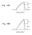
- FIGS. 16A and 16B illustrate a method for identifying whether the waveform of the transient current is convex or triangular
- FIG. 17 is a flowchart of an example of an algorithm of a program executed by a microprocessor for constructing first switch pattern determination means of the control device in FIG. 2 ;
- FIG. 18 is a flowchart of another example of an algorithm of a program executed by the microprocessor for constructing the first switch pattern deciding means of the control device in FIG. 2 ;
- FIG. 19A is a graph showing changes in the magnetic fluxes passing through the U-phase to W-phase cores by the transient currents
- FIG. 19B is a graph showing peak values ⁇ iu, ⁇ iv and ⁇ iw of the detected transient currents
- FIG. 19C is a table showing an initial switch pattern when the rotor is at the positions P 1 to P 13 in FIG. 3 as an inverter circuit is controlled by 120° switching control;
- FIG. 20 is a circuit diagram of a construction of hardware according to another embodiment of the present invention.
- FIG. 1 shows a construction of hardware according to an embodiment in which the present invention is applied to a rotating electric machine used as a starter generator.
- the rotating electric machine according to the embodiment is mounted in an internal combustion engine, operated as a brushless motor at the start of the engine, and after the engine is started, the rotating electric machine is operated as a magneto generator to charge a battery.
- reference numerals 1 and 2 denote a rotating electric machine and a battery, respectively, and 3 denotes an inverter circuit provided between the rotating electric machine 1 and the battery 2 .
- a reference numeral 4 denotes a controller that has a microprocessor and controls the inverter circuit 3 .
- a reference numeral 5 denotes a signal generating device that generates a pulse signal when a position of a rotor of the rotating electric machine 1 matches a predetermined position.
- a reference numeral 6 denotes a transient current energizing switch that is closed when a transient current is passed through an armature coil of the rotating electric machine 1 , and 7 denotes current detection means for detecting the transient current.
- a reference numeral 10 denotes a rotor yoke made of a ferromagnetic material such as iron and formed into a substantial cup shape.
- the rotor yoke is mounted in the internal combustion engine (not shown), with a boss provided on a center of a bottom wall of the rotor yoke being fitted to a crankshaft of the engine.
- a permanent magnet is mounted to an inner periphery of a peripheral wall 10 a of the rotor yoke 10 to produce a magnetic field with even number of poles.
- two arcuate permanent magnets M 1 and M 2 placed at a 180° interval are mounted to the inner periphery of the peripheral wall 10 a of the rotor yoke 10 by bonding or the like, and the permanent magnets are radially polarized in different polarizing directions to produce the magnetic field with two poles on the inner periphery of the rotor yoke.
- a rotor 1 A is comprised of the rotor yoke 10 and the permanent magnets M 1 and M 2 . In this embodiment, the magnet rotor 1 A is rotated counterclockwise (in a direction of the arrow CCW) in FIG. 1 during a forward rotation of the internal combustion engine.
- a stator 1 B is placed inside the magnet rotor 1 A.
- the stator 1 B is comprised of a known annular star type armature core (not shown) having a structure in which three salient poles radially protrude from an outer periphery of an annular yoke, and three-phase armature coils Lu to Lw wound around the three salient poles of the armature core.
- the three-phase armature coils Lu to Lw are star-connected, and three-phase terminals 1 u , 1 v and 1 w are drawn from ends opposite a neutral point of the armature coils.
- the stator 1 B is secured to a stator mounting portion formed on part of a casing of the internal combustion engine, and a magnetic pole portion formed on a tip of each of the three salient poles of the armature core faces a magnetic pole of a magnetic field of the magnet rotor 1 A with a predetermined gap therebetween.
- Three reluctors 11 to 13 constituted by arcuate protrusions extending circumferentially of the peripheral wall 10 a are formed at 120° intervals on an outer periphery of the peripheral wall 10 a of the rotor yoke 10 , and a signal generating rotor 5 A is comprised of the reluctors 11 to 13 and the rotor yoke 10 .
- a pulser (pulse signal generator) 5 B is placed near the signal generating rotor 5 A, and the signal generating device 5 of a magnetic flux change detection type that generates a pulse signal when detecting changes in the magnetic flux is comprised of the rotor 5 A and the pulser 5 B.
- a pulser 5 B generates pulse signals with different polarities when a leading edge and a trailing edge in a rotational direction are detected.
- the pulser 5 B is secured to the casing or the like of the engine. When the leading edge in the rotational direction of each of the reluctors 11 to 13 is detected, the pulser 5 B generates a pulse signal with a first polarity, and when the trailing edge in the rotational direction of each of the reluctors 11 to 13 is detected, the pulser 5 B generates a pulse signal with a second polarity.
- each reluctor has a polar arc angle of 60°
- the three reluctors 11 to 13 are provided at the 120° intervals, and thus the pulser 5 B generates six pulse signals at 60° intervals during one rotation of the rotor 1 A.
- the reluctors 11 to 13 and the pulser 5 B are provided so that timings of generation of the six pulse signals match six switching timings (switching timings of an excitation phase) of switch patterns of the inverter circuit when the rotating electric machine is operated as a brushless motor by 120° switching control or 180° switching control.
- the pulse signal generated by the pulser 5 B is input to a pulse signal input terminal 4 a of the controller 4 .
- the pulse signal input to the pulse signal input terminal 4 a is converted into a signal that can be identified by a microprocessor by a waveform rectifier circuit provided in the controller 4 , and input to the microprocessor in the controller 4 .
- the inverter circuit 3 is comprised of a known circuit with each side of a three-phase bridge circuit being constituted by elements including switch elements that can be controlled on/off and feedback diodes connected in anti-parallel.
- a three-phase bridge circuit being constituted by elements including switch elements that can be controlled on/off and feedback diodes connected in anti-parallel.
- three upper sides of a bride are constituted by three elements including switch elements Qu, Qv and Qw each having one end connected in common and diodes Du, Dv and Dw connected in anti-parallel with the switch elements
- three lower sides of the bridge are constituted by three elements including switch elements Qx, Qy and Qz each having one end connected to the other end of each of the switch elements Qu, Qv and Qw and the other end connected in common, and feedback diodes Dx, Dy and Dz connected in anti-parallel with the switch elements.
- Switch elements used as the switch elements Qu to Qw and Qx to Qz keep an ON state only while a drive signal is provided, and enters an OFF state when the drive signal is removed.
- MOSFETs are used as the switch elements that constitute each side of the bridge of the inverter circuit 3 , and parasitic diodes formed between drain and source of the MOSFETs are used as feedback diodes.
- a common connection point of one ends of the switch elements Qu, Qv and Qw and a common connection point of the other ends of the switch elements Qx, Qy and Qz are positive and negative DC terminals 3 a and 3 b , respectively, and connection points of the other ends of the switch elements Qu, Qv and Qw and one ends of the switch elements Qx, Qy and Qz are AC terminals 3 u , 3 v and 3 w , respectively.
- the battery 2 is connected between the DC terminals 3 a and 3 b , and three-phase terminals 1 u , 1 v and 1 w drawn from non-neutral point side terminals (terminals opposite from the neutral point) of the armature coils Lu, Lv and Lw are connected to the AC terminals 3 u , 3 v and 3 w.
- a full-wave rectifier circuit is constituted by the diodes Du, Dv, Dw, Dx, Dy and Dz, and when the rotating electric machine 1 is externally driven and operated as a magneto generator, a three-phase AC voltage induced in the armature coils Lu to Lw is converted into a DC voltage by the full-wave rectifier circuit and applied to the battery 2 .
- the transient current energizing switch 6 and the current detection means 7 are connected in series between the neutral point of the armature coils Lu to Lw and the ground.
- the current detection means 7 is constituted by a shunt resistor Ri and one end of the resistor Ri is connected to the neutral point of the armature coil.
- the transient current energizing switch 6 is constituted by an NPN transistor with an emitter being grounded, a collector of the transistor is connected to the other end of the resistor Ri. A base of the transistor is connected to a switch control signal output terminal 4 b provided on the controller 4 . Detection signals obtained across the resistor Ri are input to a transient current detection signal input terminal 4 c of the controller 4 via an arithmetical operation amplifier OP 1 .
- a transient current energizing process for performing, for each of the three-phase armature coils, a process for temporarily applying a DC voltage to the armature coil of each phase of the stator 1 B to pass the transient current through the armature coil of each phase, and a rotor position determination process for determining the position of the rotor relative to the three-phase armature coils from the transient currents passed through the three-phase armature coils in the transient current energizing process and determining the position of the rotor relative to the three-phase armature coils are performed to determine the position of the rotor 1 A.
- An excitation phase is decided that is required for rotating the rotor in a predetermined direction based on the position of the rotor thus determined, the switch pattern of the inverter circuit 3 is decided so as to pass an excitation current through the armature coil of the decided excitation phase, and the switch elements of the inverter circuit are controlled on/off with the switch pattern.
- a predetermined program is executed by the microprocessor of the controller 4 to construct various means in FIG. 2 .
- a reference numeral 20 denotes transient current energizing means, which performs, for each of the three-phase armature coils, a transient current energizing process for temporarily connecting the neutral point to the grounded potential portion in a state where a voltage is applied between a terminal opposite from the neutral point of the armature coil of each phase of the stator 1 B and the grounded potential portion to pass the transient current through the armature coil of each phase.
- a reference numeral 21 denotes first rotor position determination means, which performs processing for detecting the transient currents passed through the three-phase armature coils by the transient current energizing means 20 from an output of the current detection means 7 and determining the position of the magnetic field of the rotor 1 A relative to the three-phase armature coils Lu to Lw from the detected transient currents.
- the rotor position detection device is comprised of the transient current energizing means 20 and the first rotor position determination means 21 .
- a reference numeral 22 denotes first switch pattern deciding means
- 23 denotes first inverter control means.
- the first switch pattern deciding means 22 decides as a switch pattern a combination of the switch elements of the inverter circuit 3 that need to be turned on in order to rotate the rotor 1 A in a predetermined direction (in the embodiment, the direction of the arrow CCW) based on the position of the rotor determined by the first rotor position determination means 21 .
- the first inverter control means 23 controls the inverter circuit 3 so as to turn on the switch elements of the inverter circuit 3 according to the switch pattern decided by the first switch pattern deciding means 22 .
- a reference numeral 24 denotes second rotor position determination means for determining the position of the rotor 1 A relative to the three-phase armature coils Lu to Lw of the stator 1 B based on positional information of the rotor 1 A obtained from the pulse signal generated by the signal generating device 5
- 25 denotes second switch pattern deciding means for deciding as a switch pattern a combination of the switch elements of the inverter circuit that need to be turned on in order to rotate the rotor in a predetermined direction based on the position determined by the second rotor position determination means 24
- 26 denotes second inverter control means for controlling the inverter circuit so as to turn on the switch elements of the inverter circuit 3 according to the switch pattern decided by the second switch pattern deciding means 25 .
- a reference numeral 27 denotes control switching means, which switches control so that the inverter circuit is controlled by the first inverter control means 23 at the start of the rotating electric machine when the signal generating device 5 generates no signal, and after a rotational speed of the rotating electric machine increases to a rotational speed at which the signal generating device 5 generates a pulse signal having a level equal to or higher than a threshold, the inverter circuit is controlled by the second inverter control means 26 .
- the control switching means may be comprised so as to detect the rotational speed of the rotor and switch from control by the first inverter control means 23 to control by the second inverter control means 26 when the detected rotational speed exceeds a set value, or comprised so as to switch from the control by the first inverter control means 23 to the control by the second inverter control means 26 when the microprocessor comes to identify the output pulse signal of the signal generating device 5 .
- the armature coil of each phase is wound so that the polarity of the salient pole on which the armature coil of each phase is wound is an N pole seen from the outside when the current passes from the terminal opposite from the neutral point of the armature coil of each phase.
- the volume of the magnetic flux passing through the armature core of the stator differs according to the positional relationship between the magnetic field and the armature coil of each phase. If the rotor 1 A is rotated stepwise by 30° counterclockwise, the positions P 1 to P 12 placed in different positions at 30° intervals as shown in FIGS. 3A to 3L are considered, and a magnetic flux ⁇ passing through the U-phase armature core at the positions P 1 to P 12 with respect to a magnetomotive force by a magnet is as shown in FIG. 4 . At the positions P 6 and P 8 , the positions of the rotor are in line symmetry, and the magnetic flux passing through the U-phase armature core is the same.
- the positions of the rotor at the positions P 9 to P 12 are in line symmetry with the positions of the rotor at the positions P 5 to P 2 , and thus the volumes of the magnetic fluxes passing through the U-phase armature core at the positions P 9 , P 10 , P 11 and P 12 are the same as the volumes of the magnetic fluxes passing through the U-phase armature core at the positions P 5 , P 4 , P 3 and P 2 .
- the position P 13 shown in FIG. 4 is the same as the position P 1
- the magnetic flux passing through the U-phase armature core at the position P 13 is the same as the magnetic flux passing through the U-phase armature core at the position P 1 .
- the magnetic flux passing through the armature core when no current passes through the armature coil differs according to the relative positional relationship between the position of the magnetic field and the armature coil of each phase (the position of the rotor relative to the armature coil of each phase), an inductance of the armature coil of each phase differs according to the position of the rotor, and therefore the transient current passing through the armature coil of each phase differs according to the position of the rotor.
- the process for applying the DC voltage to the armature coil of each phase of the stator to pass the transient current through the armature coil of each phase is performed for each of the m-phase armature coils, and features of the transient currents passed through the m-phase armature coils are extracted and compared to allow determination of the position of the rotor relative to the armature coil of each phase.
- the position of the rotor relative to the V-phase and W-phase armature coils correspond to the position P 5 relative to the U-phase armature coil.
- the switch element Qv of the inverter circuit 3 is turned on and the transient current energizing switch 6 is turned on
- the switch element Qw of the inverter circuit 3 is turned on and the transient current energizing switch 6 is turned on
- the transient current corresponding to i 5 passes.
- a peak value and a waveform of the transient current passing when the DC voltage is temporarily applied to the armature coil of each phase differ according to the position of the rotor 1 A, and thus the process for temporarily applying the DC voltage to the armature coil of each phase of the stator to pass the transient current through the armature coil of each phase is performed for each of the three-phase armature coils, and peak values of the transient currents passed through the three-phase armature coils are measured and compared, or the peak values are compared and features of waveforms of the transient currents passed through the three-phase armature coils are compared to allow determination of the position of the magnetic field of the rotor relative to the three-phase armature coils.
- whether the position of the rotor is determined from the peak values of the transient currents or both the peak values and the waveforms of the transient currents is decided according to whether the position of the rotor required for deciding a switching position of the switch pattern can be obtained. Specifically, when the positional information of the rotor required for deciding the switching position of the switch pattern can be obtained simply by comparing the peak values of the transient currents passed through the three-phase armature coils, the peak values only of the transient currents are used to determine the position of the rotor.
- both the peak values and the waveforms (the features extracted from the waveforms) of the transient currents are used to determine the position of the rotor.
- the features of the waveforms of the transient currents passed through the m-phase armature coils are extracted and compared.
- the extraction of the features of the waveforms of the transient currents can be performed, for example, by the following methods.
- a waveform is determined from a rate of change with time at a leading edge of the transient current i. For example, ib1/t1 and ia1/t1 are compared or ib2/t2 and ia2/t2 are compared.
- the inverter circuit is controlled so as to turn on the switch elements of the inverter circuit according to the decided switch pattern to allow rotation of the rotor in the predetermined direction.
- an excitation phase is decided by the second switch pattern deciding means 25 based on the positional information of the rotor obtained from the pulse signal output by the signal generating rotor 5 , and the control of the inverter circuit 3 is switched by the control switching means 27 from the control by the first inverter control means to the second inverter control means 26 , and the inverter circuit 3 is controlled so as to turn on the switch elements of the inverter circuit 3 with the switch pattern decided by the second switch pattern deciding means 25 to operate the rotating electric machine as a brushless motor.
- FIG. 10A A switch pattern, together with the waveforms of the output pulse signals of the signal generating device 5 , is shown in FIG. 10A , which is decided based on the output pulse signals of the signal generating device 5 in the case where excitation control is switched to the control by the second inverter control means 26 and the inverter circuit 3 is controlled so as to pass the excitation current through the armature coils Lu to Lw by 180° switching when the rotating electric machine is started and the rotor 1 A reaches the position P 1 in FIG. 3A .
- FIG. 10A is decided based on the output pulse signals of the signal generating device 5 in the case where excitation control is switched to the control by the second inverter control means 26 and the inverter circuit 3 is controlled so as to pass the excitation current through the armature coils Lu to Lw by 180° switching when the rotating electric machine is started and the rotor 1 A reaches the position P 1 in FIG. 3A .
- Vf 11 and Vr 11 show pulse signals generated by the pulser 5 B detecting a leading edge f 11 and a trailing edge r 11 of the reluctor 11 in the rotational direction when the rotor is at the positions P 1 and P 3
- Vf 12 and Vr 12 show pulse signals generated by the pulser 5 B detecting a leading edge f 12 and a trailing edge r 12 of the reluctor 12 in the rotational direction when the rotor is at the positions P 5 and P 7
- Vf 13 and Vr 13 show pulse signals generated by the pulser 5 B detecting a leading edge f 13 and a trailing edge r 13 of the reluctor 13 in the rotational direction when the rotor is at the positions P 9 and P 11 .
- the table in FIG. 10B shows switch patterns of the inverter circuit, and in FIG. 10B , the switch elements Qu, Qv and Qw are turned on in sections indicated by reference characters U, V and W, and the switch elements Qx, Qy and Qz are turned on in sections indicated by reference characters X, Y and Z.
- the combination (switch pattern) of the switch elements to be turned on is switched from (Qu, Qy, Qz) to (Qu, Qv, Qz) to switch from the state where the excitation current passed through the armature coil Lu is passed out through the armature coils Lv and Lw to a state where the excitation current passed through the armature coils Lu and Lv is passed out through the armature coil Lw.
- the combination of the switch elements to be turned on is switched from (Qu, Qv, Qz) to (Qx, Qv, Qz) to switch from the state where the excitation current passed through the armature coils Lu and Lv is passed out through the armature coil Lw to a state where the excitation current passed through the armature coil Lv is passed out through the armature coils Lu and Lw.
- the reluctor and the pulser are provided so as to generate the pulse signal at the position where the switch pattern is switched, and thus if the position of the rotor when the control is switched (the position P 1 in the example in FIG. 10 ) is decided, the excitation phase can be easily decided.
- the rotating electric machine When the rotor can be only slightly rotated because of a heavy load at the start of the rotating electric machine, the rotating electric machine is driven for a certain time with an initial switch pattern, and if the pulser generates no pulse signal during the driving, the driving is temporarily stopped to again determine the position of the rotor, decide a new switch pattern based on the determination results, and control the inverter circuit so as to turn on the switch elements of the inverter circuit with the decided switch pattern. This control is continued while the rotation speed is too low to generate a pulse signal that can be identified by the pulser 5 B, thereby allowing continuous rotation of the rotating electric machine.
- the rotating electric machine When the rotating electric machine is operated as a motor for starting the internal combustion engine, it is considered that the rotational speed cannot be sufficiently increased in a compression stoke of the engine, and the pulse signal that can be identified by the pulser cannot be generated. If the above described control is continued in such a case, the rotational speed increases when the compression stroke of a combustion cycle of the engine is finished and an expansion stroke is started, and thus the pulse signal that can be identified by the pulser can be generated to switch to the control by the second inverter control means, and sufficient torque is generated in a next compression stroke to perform a function as a starter motor.
- the inverter circuit is controlled by the switch pattern decided based on the position of the rotor determined from the transient current passed through the armature coil to start the rotating electric machine. This allows the initial switch pattern in the process for starting the rotating electric machine to be decided to start the rotating electric machine without using a sensor having low heat resistance such as a Hall element or an expensive sensor such as a resolver.
- the switch pattern can be decide to excite the armature coil based on the position of the rotor determined using the rotational angle information obtained from the pulse signal output by the signal generating device 5 , thereby allowing rotation of the rotating electric machine as a general brushless motor.
- FIG. 11 shows changes ⁇ 1 and ⁇ 2 in the magnetic flux ⁇ passing through the U-phase core when the rotor is at the positions P 1 , P 2 , P 3 , . . . (P 8 and greater are omitted) and the switch 6 in FIG. 1 is turned on to pass the transient current.
- Changes in the magnetic flux passing through the U-phase to W-phase cores when the rotor is at the positions P 1 to P 12 and the switch 6 is turned on to pass the transient currents through the U-phase to W-phase armature coils are collectively shown in the table in FIG. 12 .
- the changes in the magnetic flux passing through the U-phase to W-phase cores are shown in curves in FIG. 13A , and peak values ⁇ iu, ⁇ iv and ⁇ iw of the detected transient currents are as shown in FIG. 13B .
- a combination of switch elements of the inverter circuit that are to be first turned on is decided as an initial switch pattern from the transient currents in FIG. 13B , and a drive signal is provided to the switch elements of the inverter circuit 3 so as to turn on the switch elements of the inverter circuit with the decided switch pattern, thereby allowing rotation of the rotor.
- FIG. 13C shows initial switch patterns when the rotor is at the positions P 1 to P 13 as control for the inverter circuit by 180° switching control.
- reference characters U, V, W, X, Y and Z show that the switch elements Qu, Qv, Qw, Qx, Qy and Qz are turned on.
- the switch pattern (U, Y, W) means that the switch elements Qu, Qy and Qw are turned on.
- the switch pattern is uniquely decided according to the order of levels of the peak values ⁇ iu, ⁇ iv and ⁇ iw of the transient currents shown in FIG. 13B , but in other positions, the switch pattern cannot be decided only according to the order of the levels of the transient currents.
- the order of the levels of the peak values ⁇ iu, ⁇ iv and ⁇ iw of the transient currents at the positions P 1 , P 5 and P 9 is the same as the order of levels of the peak values ⁇ iu, ⁇ iv and ⁇ iw of the transient currents at the positions P 7 , P 11 and P 3 .
- the initial switch pattern of the inverter circuit cannot be decided only by checking the order of the levels of the peak values of the transient currents.
- the waveforms of the transient currents ⁇ iu to ⁇ iw for example, the waveforms of the transient currents ⁇ iu to ⁇ iw at the position P 1 are as shown in FIGS. 14A to 14C , while the waveforms of the transient current ⁇ iu to ⁇ iw at the position P 7 are as shown in FIGS. 15A to 15C , and the waveform of the U-phase transient current ⁇ iu at the position P 1 is different from that at the position P 7 .
- the transient current passes in a direction of demagnetizing the saturated U-phase core to cause a magnetic flux change ⁇ 1, and thus the waveform of the transient current is convex (a waveform with a curved leading edge like a quadratic curve) rather than triangular, and the transient current passing through the U-phase armature coil becomes the maximum.
- the maximum transient current is the U-phase transient current, it is determined whether the waveform is convex rather triangular. Then, when it is determined that the waveform is convex, it can be determined that the rotor is at the position P 1 .
- ⁇ i2/ ⁇ t are calculated to determine whether the difference between the rate of change in the first half ⁇ i1/ ⁇ t and the rate of change in the second half ⁇ i2/ ⁇ t is a set value or more.
- the waveform of the transient current is convex or triangular, and from the determination results, it can be determined whether the rotor is at the position P 1 or P 7 .
- FIG. 17 shows an example of an algorithm of a program executed by the microprocessor for constructing the first switch pattern determination means 22 that decides the initial switch pattern of the inverter circuit when the rotating electric machine is operated as the brushless motor from the order of the levels of the peak values of the transient currents and the waveform of the maximum transient current obtained by performing the transient current energizing process.
- Step 1 a maximum ⁇ imax among ⁇ iu, ⁇ iv and ⁇ iw is found when the process for determining the initial switch pattern is started.
- Step 2 a maximum ⁇ imax among ⁇ iu, ⁇ iv and ⁇ iw is found when the process for determining the initial switch pattern is started.
- Step 3 a maximum ⁇ imax among ⁇ iu, ⁇ iv and ⁇ iw is found when the process for determining the initial switch pattern is started.
- the initial switch pattern is decided as UVZ in Step 5
- the initial switch pattern is decided as XYW in Step 6 .
- Step 3 ⁇ iv and ⁇ iw are compared in Step 3 , and when it is determined as in Step 7 that ⁇ iv is smaller than ⁇ iw, the process goes to Step 8 to determine whether the waveform of ⁇ iu is convex.
- the initial switch pattern is decided as XVZ in Step 9
- the initial switch pattern is decided as UYW in Step 10 .
- Step 11 when it is determined that the peak value of the maximum transient current found in Step 1 is ⁇ iv, then ⁇ iw and ⁇ iu are compared. When ⁇ iw is larger than ⁇ iu as in Step 12 , the process moves to Step 13 to determine whether the waveform of ⁇ iv is convex. When it is determined that the waveform of ⁇ iv is not convex, the initial switch pattern is decided as XVW in Step 14 , and when it is determined that the waveform of ⁇ iv is convex, the initial switch pattern is decided as UYZ in Step 15 .
- Step 16 when it is determined as in Step 16 that ⁇ iw is smaller than ⁇ iu, the process goes to Step 17 to determine whether the waveform of ⁇ iv is convex.
- the initial switch pattern is decided as XYW in Step 18
- the initial switch pattern is decided as UVZ in Step 19 .
- Step 20 when it is determined that the peak value of the maximum transient current found in Step 1 is ⁇ iw, then ⁇ iu and ⁇ iv are compared. When ⁇ iu is larger than ⁇ iv as in Step 21 , the process moves to Step 22 to determine whether the waveform of ⁇ iw is convex. When it is determined that the waveform of ⁇ iw is not convex, the initial switch pattern is decided as UYW in Step 23 , and when it is determined that the waveform of ⁇ iw is convex, the initial switch pattern is decided as XVZ in Step 24 .
- Step 25 when it is determined as in Step 25 that ⁇ iu is smaller than ⁇ iv, the process goes to Step 26 to determine whether the waveform of ⁇ iw is convex.
- the initial switch pattern is decided as UYZ in Step 27
- the initial switch pattern is decided as XVW in Step 28 .
- FIG. 18 shows a flowchart of an algorithm of a program executed by the microprocessor for constructing the first switch pattern deciding means 22 when the position is determined by using a relationship such that the peak values of the transient currents passing through the armature coils of all phases are larger than the determination value ⁇ is at the particular positions and not at other positions.
- the flowchart in FIG. 18 shows a flowchart of an algorithm of a program executed by the microprocessor for constructing the first switch pattern deciding means 22 when the position is determined by using a relationship such that the peak values of the transient currents passing through the armature coils of all phases are larger than the determination value ⁇ is at the particular positions and not at other positions.
- Step 18 is similar to the flowchart in FIG. 16 except that it is determined whether the peak values ⁇ iu, ⁇ iv and ⁇ iw of the transient currents of all phases are larger than the determination value ⁇ is in Steps 4 , 8 , 13 , 17 , 22 and 26 , and thus detailed descriptions thereof will be omitted.
- the control switching means 27 switches control so that the inverter circuit 3 is controlled by the first inverter control means 23 at the start of the rotating electric machine 1 , and after the signal generating device enters the state of generating the pulse signal having the level equal to or higher than the threshold, the inverter circuit is controlled by the second inverter control means 26 .
- the switch pattern is switched by the pulse generated by the signal generating device 5 to operate the rotating electric machine as the brushless motor.
- the current detection means 7 is inserted between the transient current energizing switch 6 and the neutral point of the armature coils.
- the transient current energizing switch 6 may be connected between the neutral point of the armature coils Lu to Lw and the ground, shunt resistors Riu, Riv and Riw that constitute current detection means may be inserted between the non-neutral point side terminals 1 u , 1 v and 1 w of the three-phase armature coils and the AC terminals 3 u , 3 v and 3 v of the inverter circuit 3 , and current detection signals obtained across the resistors may be input to the controller 4 via a detection circuit using arithmetical operation amplifiers OP 1 u , OP 1 v and OP 1 w.
- the means for detecting the transient current is not limited to the shunt resistor, but a current transformer or a Hall element may be used as current detection means.
- the switching control of the inverter circuit is performed by the 180° switching control, but the present invention may be of course applied to the case where the inverter circuit is controlled by 120° switching control.
- FIG. 19 shows magnetic fluxes ⁇ passing through the U-phase to W-phase cores when the rotor is at the positions P 1 to P 12 and the transient currents are passed through the U-phase to W-phase armature coils, peak values ⁇ iu, ⁇ iv and ⁇ iw of the detected transient currents, and changes in a switch pattern when the inverter circuit 3 is controlled by the 120° switching control.
- an initial switch pattern is switched according to whether a peak value of a transient current presenting an intermediate value among the peak values ⁇ iu, ⁇ iv and ⁇ iw of the transient currents passed through the three-phase armature coils in a transient current energizing process is a determination value Is or more or less at a position where the peak value of the transient current presenting the intermediate value passes the determination value ⁇ Is.
- the switch pattern is switched to (U, Y) at a position P 2 where ⁇ iu presenting the intermediate value among the peak values ⁇ iu, ⁇ iv and ⁇ iw is the determination value ⁇ Is or less, and the switch pattern is switched to (U, Z) at a position P 4 where ⁇ iv presenting the intermediate value among the peak values ⁇ iu, ⁇ iv and ⁇ iw is the determination value ⁇ Is or more.
- the switch pattern is switched to (V, Z) at a position P 6 where ⁇ iv presenting the intermediate value among the peak values ⁇ iu, ⁇ iv and ⁇ iw is the determination value ⁇ Is or less.
- the rotating electric machine includes the three-phase armature coils, but the present invention may be applied to a rotating electric machine including polyphase armature coils with more phases.
- the magnetic field of the rotor has two poles, but the magnetic field of the rotor may have even number of poles.
- the magnetic field of the rotor is produced by mounting a permanent magnet to a rotor yoke, but the present invention may be applied to the case where the magnetic field of the rotor is produced by passing an excitation current through an excitation coil wound around the rotor core.
- the star-connected annular cores having the three poles are used as the armature cores of the stator with the three-phase armature coils being wound around the three salient poles of the cores, but the present invention may be applied to the case where the three-phase (generally m-phase) armature coils are wound around a slot of the armature core in a distributed manner.
Abstract
Description
i=(E/r)[1−exp {−(r/L)t}] (1)
-
- where the resistance r is fixed, and the inductance L takes values of La, Lb and Lc (La<Lb<Lc), then a relationship r/La>r/Lb>r/Lc is satisfied. Thus, transient currents ia, ib and ic passing when the inductance values are La, Lb and Lc with respect to time t are as shown in
FIG. 6 .
- where the resistance r is fixed, and the inductance L takes values of La, Lb and Lc (La<Lb<Lc), then a relationship r/La>r/Lb>r/Lc is satisfied. Thus, transient currents ia, ib and ic passing when the inductance values are La, Lb and Lc with respect to time t are as shown in
L1=nΔφ1/ΔI (2)
L5=nΔφ5/ΔI (3)
-
- where Δφ1<Δφ5, and thus L1<L5, and transient currents i1 and i5 passing when the rotor is at the positions P1 and P5 are as shown in
FIG. 8 .
- where Δφ1<Δφ5, and thus L1<L5, and transient currents i1 and i5 passing when the rotor is at the positions P1 and P5 are as shown in
Claims (8)
Applications Claiming Priority (2)
| Application Number | Priority Date | Filing Date | Title |
|---|---|---|---|
| JP2004-225734 | 2004-08-02 | ||
| JP2004225734A JP4581544B2 (en) | 2004-08-02 | 2004-08-02 | Rotor electric machine rotor position determination method, rotor position determination device, and rotary electric machine control device |
Publications (2)
| Publication Number | Publication Date |
|---|---|
| US20060022623A1 US20060022623A1 (en) | 2006-02-02 |
| US7026774B2 true US7026774B2 (en) | 2006-04-11 |
Family
ID=35731365
Family Applications (1)
| Application Number | Title | Priority Date | Filing Date |
|---|---|---|---|
| US11/188,674 Active US7026774B2 (en) | 2004-08-02 | 2005-07-25 | Rotor position determination device of rotating electric machine and control device of rotating electric machine |
Country Status (2)
| Country | Link |
|---|---|
| US (1) | US7026774B2 (en) |
| JP (1) | JP4581544B2 (en) |
Cited By (16)
| Publication number | Priority date | Publication date | Assignee | Title |
|---|---|---|---|---|
| US20060006833A1 (en) * | 2004-07-06 | 2006-01-12 | Wlodzimierz Koczara | Electrical machine rotor position identification |
| US20060043919A1 (en) * | 2004-09-01 | 2006-03-02 | Aisin Aw Co., Ltd. | Motor drive control apparatus, motor drive control method and program of the same |
| US20060043915A1 (en) * | 2004-08-24 | 2006-03-02 | Samsung Electronics Co., Ltd. | Motor driving apparatus, and initial driving method for three-phase motor |
| US20090058087A1 (en) * | 2007-08-31 | 2009-03-05 | Denso Corporation | On-vehicle rotary electric machine operating on two modes of rectification |
| US20090278485A1 (en) * | 2005-12-15 | 2009-11-12 | Rolf Strothmann | Device and Method for Determining the Rotational Position of a Rotor in an Electric Machine |
| US20100052585A1 (en) * | 2008-09-02 | 2010-03-04 | Stmicroelectronics, Inc. | Motor controller with drive-signal conditioning |
| US20100102768A1 (en) * | 2008-10-24 | 2010-04-29 | Foo Leng Leong | Determining stuck conditions for electric motors using inductive sensing |
| US20100119386A1 (en) * | 2008-11-13 | 2010-05-13 | Ravishanker Krishnamoorthy | Motor control system |
| US20110204831A1 (en) * | 2010-02-25 | 2011-08-25 | Hitachi, Ltd. | Drive device for alternating current motor and electric motor vehicle |
| US20130343104A1 (en) * | 2012-06-20 | 2013-12-26 | Control Techniques Limited | System And Method For Managing Recovery Of Control In An Electrical System |
| US8807956B2 (en) | 2008-11-13 | 2014-08-19 | Marvell World Trade Ltd. | Apparatus and method for controlling speed of a fan via a first control module connected by a cable and/or conductors between a motor and a second control module |
| US20150229159A1 (en) * | 2014-02-07 | 2015-08-13 | Honda Motor Co., Ltd. | Battery charging apparatus for vehicle |
| US20160068066A1 (en) * | 2013-04-18 | 2016-03-10 | Toyota Jidosha Kabushiki Kaisha | External power supply system |
| US9998042B2 (en) | 2013-03-04 | 2018-06-12 | Seagate Technology Llc | Torque disturbance cancellation for a motor |
| US10116243B2 (en) * | 2016-06-16 | 2018-10-30 | Allegro Microsystems, Llc | Determining motor position with complementary drive and detect and slight move |
| US10181810B2 (en) * | 2016-06-16 | 2019-01-15 | Allegro Microsystems, Llc | Determining motor position with complementary driving and detection and current injection |
Families Citing this family (14)
| Publication number | Priority date | Publication date | Assignee | Title |
|---|---|---|---|---|
| EP2051368A1 (en) * | 2007-10-16 | 2009-04-22 | ABB Schweiz AG | Method for determining the rotor position of a separately excited electric machine |
| JP4901695B2 (en) * | 2007-11-02 | 2012-03-21 | 本田技研工業株式会社 | Characteristic measurement device, characteristic visualization device, and current control device |
| DE102010028479A1 (en) * | 2010-05-03 | 2011-11-03 | Robert Bosch Gmbh | Method and device for driving a permanent magnet excited electrical machine |
| JP5875265B2 (en) * | 2011-07-04 | 2016-03-02 | キヤノン株式会社 | Stepping motor drive control device, drive control method, drive control system, and optical apparatus |
| CN103178768A (en) * | 2011-12-26 | 2013-06-26 | 上海大郡动力控制技术有限公司 | Device for detecting initial position of rotor of permanent-magnetic synchronous motor and using method thereof |
| US20130193813A1 (en) * | 2012-01-31 | 2013-08-01 | Hamilton Sundstrand Corporation | Integrated high-voltage direct current electric power generating system |
| JP5758833B2 (en) * | 2012-03-30 | 2015-08-05 | 本田技研工業株式会社 | Battery charger |
| US9729088B2 (en) | 2013-04-22 | 2017-08-08 | Nxp Usa, Inc. | Method, computer program product and controller for starting-up a switched reluctance motor, and electrical apparatus implementing same |
| JP6426420B2 (en) * | 2014-09-29 | 2018-11-21 | ルネサスエレクトロニクス株式会社 | Semiconductor device and electric device |
| US10030623B2 (en) * | 2014-12-23 | 2018-07-24 | Stmicroelectronics International N.V. | Method and system for improving the efficiency of 2-wheeled and 3-wheeled motor vehicles |
| DE102016119892B4 (en) * | 2015-10-21 | 2022-04-28 | Denso Corporation | Control device for a rotating electrical machine |
| JP6284207B1 (en) | 2016-11-08 | 2018-02-28 | 北斗制御株式会社 | Electric field position detection method |
| JP2019213351A (en) * | 2018-06-05 | 2019-12-12 | コニカミノルタ株式会社 | Control device of permanent magnet synchronous motor and image forming apparatus |
| JP7044008B2 (en) * | 2018-08-03 | 2022-03-30 | 株式会社デンソー | motor |
Citations (16)
| Publication number | Priority date | Publication date | Assignee | Title |
|---|---|---|---|---|
| US4140952A (en) * | 1977-03-23 | 1979-02-20 | Chrysler Corporation | Offset compensated electronic current sensor and controller |
| JPS60194782A (en) | 1984-03-16 | 1985-10-03 | Nippon Denso Co Ltd | Controller of brushless motor |
| US4772839A (en) * | 1987-10-27 | 1988-09-20 | General Electric Company | Rotor position estimator for switched reluctance motor |
| US4874993A (en) * | 1987-10-31 | 1989-10-17 | Sony Corporation | Sensorless brushless motor |
| US5604412A (en) * | 1993-03-19 | 1997-02-18 | Nidec Corporation | Brushless motor and a control circuit thereof |
| US5701064A (en) * | 1995-10-27 | 1997-12-23 | Emerson Electric Co. | Rotor position sensing in a dynamoelectric machine using coupling between machine coils |
| US5783917A (en) * | 1995-10-13 | 1998-07-21 | Zexel Corporation | Method and device for driving DC brushless motor |
| US5821786A (en) * | 1993-08-03 | 1998-10-13 | Kabushiki Kaisha Toshiba | Semiconductor integrated circuit having function for evaluating AC performance |
| US5854548A (en) * | 1996-02-29 | 1998-12-29 | Toyota Jidosha Kabushiki Kaisha | Electrical angle detecting device and synchronous motor drive device |
| US5886486A (en) * | 1997-02-06 | 1999-03-23 | Samsung Electronics Co., Ltd. | Sensorless brushless DC motor |
| US6051942A (en) * | 1996-04-12 | 2000-04-18 | Emerson Electric Motor Co. | Method and apparatus for controlling a switched reluctance machine |
| US6288513B1 (en) * | 1999-01-11 | 2001-09-11 | Switched Reluctance Drives Limited | Rotor position detection in switched reluctance machines |
| US6483270B1 (en) * | 1998-07-16 | 2002-11-19 | Seiko Epson Corporation | Method and device for controlling position sensorless motor |
| US6664750B2 (en) * | 2002-03-13 | 2003-12-16 | Pelko Electric (Hk) Ltd. | D.C. motor bridge coil driver |
| JP2004080931A (en) | 2002-08-20 | 2004-03-11 | Kokusan Denki Co Ltd | Starter generator for internal combustion engine |
| JP2004173482A (en) | 2002-11-05 | 2004-06-17 | Kokusan Denki Co Ltd | Power generating device provided with magnet generator |
Family Cites Families (6)
| Publication number | Priority date | Publication date | Assignee | Title |
|---|---|---|---|---|
| JPS54113817A (en) * | 1978-02-27 | 1979-09-05 | Toshiba Corp | Thyristor motor |
| JP3381408B2 (en) * | 1993-10-26 | 2003-02-24 | トヨタ自動車株式会社 | Electric angle detecting device and synchronous motor driving device using the same |
| JP3389329B2 (en) * | 1994-05-31 | 2003-03-24 | 三洋電機株式会社 | Motor drive |
| DE19729238C1 (en) * | 1997-07-09 | 1998-08-27 | Telefunken Microelectron | Speed determining method for mechanically commutated DC motors |
| JPWO2002027182A1 (en) * | 2000-09-28 | 2004-02-05 | 株式会社ミツバ | Engine starter |
| JP2002165480A (en) * | 2000-11-21 | 2002-06-07 | Sharp Corp | Brushless motor controller and inverter washing machine provided with the same |
-
2004
- 2004-08-02 JP JP2004225734A patent/JP4581544B2/en not_active Expired - Fee Related
-
2005
- 2005-07-25 US US11/188,674 patent/US7026774B2/en active Active
Patent Citations (16)
| Publication number | Priority date | Publication date | Assignee | Title |
|---|---|---|---|---|
| US4140952A (en) * | 1977-03-23 | 1979-02-20 | Chrysler Corporation | Offset compensated electronic current sensor and controller |
| JPS60194782A (en) | 1984-03-16 | 1985-10-03 | Nippon Denso Co Ltd | Controller of brushless motor |
| US4772839A (en) * | 1987-10-27 | 1988-09-20 | General Electric Company | Rotor position estimator for switched reluctance motor |
| US4874993A (en) * | 1987-10-31 | 1989-10-17 | Sony Corporation | Sensorless brushless motor |
| US5604412A (en) * | 1993-03-19 | 1997-02-18 | Nidec Corporation | Brushless motor and a control circuit thereof |
| US5821786A (en) * | 1993-08-03 | 1998-10-13 | Kabushiki Kaisha Toshiba | Semiconductor integrated circuit having function for evaluating AC performance |
| US5783917A (en) * | 1995-10-13 | 1998-07-21 | Zexel Corporation | Method and device for driving DC brushless motor |
| US5701064A (en) * | 1995-10-27 | 1997-12-23 | Emerson Electric Co. | Rotor position sensing in a dynamoelectric machine using coupling between machine coils |
| US5854548A (en) * | 1996-02-29 | 1998-12-29 | Toyota Jidosha Kabushiki Kaisha | Electrical angle detecting device and synchronous motor drive device |
| US6051942A (en) * | 1996-04-12 | 2000-04-18 | Emerson Electric Motor Co. | Method and apparatus for controlling a switched reluctance machine |
| US5886486A (en) * | 1997-02-06 | 1999-03-23 | Samsung Electronics Co., Ltd. | Sensorless brushless DC motor |
| US6483270B1 (en) * | 1998-07-16 | 2002-11-19 | Seiko Epson Corporation | Method and device for controlling position sensorless motor |
| US6288513B1 (en) * | 1999-01-11 | 2001-09-11 | Switched Reluctance Drives Limited | Rotor position detection in switched reluctance machines |
| US6664750B2 (en) * | 2002-03-13 | 2003-12-16 | Pelko Electric (Hk) Ltd. | D.C. motor bridge coil driver |
| JP2004080931A (en) | 2002-08-20 | 2004-03-11 | Kokusan Denki Co Ltd | Starter generator for internal combustion engine |
| JP2004173482A (en) | 2002-11-05 | 2004-06-17 | Kokusan Denki Co Ltd | Power generating device provided with magnet generator |
Cited By (35)
| Publication number | Priority date | Publication date | Assignee | Title |
|---|---|---|---|---|
| US7233123B2 (en) * | 2004-07-06 | 2007-06-19 | Cummins Generator Technologies Limited | Electrical machine rotor position identification |
| US20060006833A1 (en) * | 2004-07-06 | 2006-01-12 | Wlodzimierz Koczara | Electrical machine rotor position identification |
| US20060043915A1 (en) * | 2004-08-24 | 2006-03-02 | Samsung Electronics Co., Ltd. | Motor driving apparatus, and initial driving method for three-phase motor |
| US7466094B2 (en) * | 2004-08-24 | 2008-12-16 | Samsung Electronics Co., Ltd. | Motor driving apparatus, and initial driving method for three-phase motor |
| US20060043919A1 (en) * | 2004-09-01 | 2006-03-02 | Aisin Aw Co., Ltd. | Motor drive control apparatus, motor drive control method and program of the same |
| US7339333B2 (en) * | 2004-09-01 | 2008-03-04 | Aisin Aw Co., Ltd. | Motor drive control apparatus, motor drive control method and program of the same |
| US20090278485A1 (en) * | 2005-12-15 | 2009-11-12 | Rolf Strothmann | Device and Method for Determining the Rotational Position of a Rotor in an Electric Machine |
| US8222847B2 (en) * | 2005-12-15 | 2012-07-17 | Rolf Strothmann | Device and method for determining the rotational position of a rotor in an electric machine |
| US8053915B2 (en) * | 2007-08-31 | 2011-11-08 | Denso Corporation | On-vehicle rotary electric machine operating on two modes of rectification |
| US20090058087A1 (en) * | 2007-08-31 | 2009-03-05 | Denso Corporation | On-vehicle rotary electric machine operating on two modes of rectification |
| US20100052585A1 (en) * | 2008-09-02 | 2010-03-04 | Stmicroelectronics, Inc. | Motor controller with drive-signal conditioning |
| US8749183B2 (en) * | 2008-09-02 | 2014-06-10 | Stmicroelectronics, Inc. | Determining a position of a motor using an on-chip component |
| US9431934B2 (en) | 2008-09-02 | 2016-08-30 | Stmicroelectronics, Inc. | Motor controller with drive-signal conditioning |
| US20100052587A1 (en) * | 2008-09-02 | 2010-03-04 | Stmicroelectronics, Inc. | Determining a position of a motor using an on-chip component |
| US9362855B2 (en) | 2008-09-02 | 2016-06-07 | Stmicroelectronics, Inc. | Determining a position of a motor using an on-chip component |
| US8754602B2 (en) | 2008-09-02 | 2014-06-17 | Stmicroelectronics, Inc. | Motor controller with drive-signal conditioning |
| US20100102768A1 (en) * | 2008-10-24 | 2010-04-29 | Foo Leng Leong | Determining stuck conditions for electric motors using inductive sensing |
| US8143825B2 (en) * | 2008-10-24 | 2012-03-27 | Marvell World Trade Ltd. | Determining stuck conditions for electric motors using inductive sensing |
| US20120176072A1 (en) * | 2008-10-24 | 2012-07-12 | Foo Leng Leong | Determining stuck conditions for electric motors using inductive sensing |
| US8405330B2 (en) * | 2008-10-24 | 2013-03-26 | Marvell World Trade Ltd. | Determining stuck conditions for electric motors using inductive sensing |
| US8807956B2 (en) | 2008-11-13 | 2014-08-19 | Marvell World Trade Ltd. | Apparatus and method for controlling speed of a fan via a first control module connected by a cable and/or conductors between a motor and a second control module |
| US9695832B2 (en) | 2008-11-13 | 2017-07-04 | Marvell World Trade Ltd. | Apparatuses for controlling operation of a motor of a fan assembly based on an induced voltage or a back electromotive force |
| US20100119386A1 (en) * | 2008-11-13 | 2010-05-13 | Ravishanker Krishnamoorthy | Motor control system |
| US8277198B2 (en) | 2008-11-13 | 2012-10-02 | Marvell International Ltd. | Fan motor control systems |
| US8674647B2 (en) * | 2010-02-25 | 2014-03-18 | Hitachi, Ltd. | Drive device for alternating current motor and electric motor vehicle |
| US20110204831A1 (en) * | 2010-02-25 | 2011-08-25 | Hitachi, Ltd. | Drive device for alternating current motor and electric motor vehicle |
| US20130343104A1 (en) * | 2012-06-20 | 2013-12-26 | Control Techniques Limited | System And Method For Managing Recovery Of Control In An Electrical System |
| US9231467B2 (en) * | 2012-06-20 | 2016-01-05 | Control Techniques Limited | System and method for managing recovery of control in an electrical system |
| US9998042B2 (en) | 2013-03-04 | 2018-06-12 | Seagate Technology Llc | Torque disturbance cancellation for a motor |
| US20160068066A1 (en) * | 2013-04-18 | 2016-03-10 | Toyota Jidosha Kabushiki Kaisha | External power supply system |
| US9539903B2 (en) * | 2013-04-18 | 2017-01-10 | Toyota Jidosha Kabushiki Kaisha | External power supply system |
| US20150229159A1 (en) * | 2014-02-07 | 2015-08-13 | Honda Motor Co., Ltd. | Battery charging apparatus for vehicle |
| US9614397B2 (en) * | 2014-02-07 | 2017-04-04 | Honda Motor Co., Ltd. | Battery charging apparatus for vehicle |
| US10116243B2 (en) * | 2016-06-16 | 2018-10-30 | Allegro Microsystems, Llc | Determining motor position with complementary drive and detect and slight move |
| US10181810B2 (en) * | 2016-06-16 | 2019-01-15 | Allegro Microsystems, Llc | Determining motor position with complementary driving and detection and current injection |
Also Published As
| Publication number | Publication date |
|---|---|
| JP4581544B2 (en) | 2010-11-17 |
| US20060022623A1 (en) | 2006-02-02 |
| JP2006050714A (en) | 2006-02-16 |
Similar Documents
| Publication | Publication Date | Title |
|---|---|---|
| US7026774B2 (en) | Rotor position determination device of rotating electric machine and control device of rotating electric machine | |
| US7081738B2 (en) | Generating device having magneto generator | |
| US6940259B2 (en) | Generating device including magneto generator | |
| US7683587B2 (en) | Generation device | |
| US6787931B2 (en) | Starter generator for internal combustion engine | |
| JPH1146456A (en) | Generator | |
| CN103563241A (en) | Brushless motor control device and brushless motor control method | |
| KR20240012617A (en) | System and method for preventing permanent magnet demagnetization in electrical machines | |
| US9602037B2 (en) | Motor drive device and motor drive system | |
| US6177777B1 (en) | Actuation and control method and device, particularly for synchronous permanent-magnet motors | |
| EP1067670A2 (en) | Controlling method forswitched reluctance motor method and motor having a low peak current | |
| Yang et al. | Position detection and drive of a toroidal switched reluctance motor (TSRM) using search coils | |
| JP2017131000A (en) | Sensorless drive method for three-phase brushless motor | |
| US7246029B2 (en) | Electric machine with actively controlled switches | |
| KR101079354B1 (en) | Sensorless driving apparatus for single-phase SRM using residual flux and method therefor | |
| JP3651352B2 (en) | SR motor control method and SR motor | |
| JP2004023900A (en) | Controller of starter generator for internal combustion engine | |
| JP4501365B2 (en) | Winding field motor control device | |
| JP6643968B2 (en) | SR motor control system and SR motor control method | |
| JP4715494B2 (en) | Brushless motor control method and control apparatus | |
| TWI424659B (en) | Method for detecting initial magnetic pole position in permanent-magnet motor | |
| JP6951008B1 (en) | Rotor position detection method for sensorless motor and sensorless motor drive method | |
| Bhosale et al. | Performance comparison of Two PWM techniques applied to BLDC motor control | |
| Savsani et al. | Study on Commutation Torque Ripple Reduction Strategy for Brushless DC Motor Targeting Electric Vehicle Applications | |
| Nugroho et al. | Comparative Control Strategy of Asymmetric Bridge Converter for Switched Reluctance Motor |
Legal Events
| Date | Code | Title | Description |
|---|---|---|---|
| AS | Assignment |
Owner name: KOKUSAN DENKI CO., LTD., JAPAN Free format text: ASSIGNMENT OF ASSIGNORS INTEREST;ASSIGNORS:INABA, YUTAKA;TAKAHASHI, MASAKATSU;NAKAGAWA, TOMOHIRO;REEL/FRAME:016817/0168 Effective date: 20050620 |
|
| FEPP | Fee payment procedure |
Free format text: PAYOR NUMBER ASSIGNED (ORIGINAL EVENT CODE: ASPN); ENTITY STATUS OF PATENT OWNER: LARGE ENTITY |
|
| STCF | Information on status: patent grant |
Free format text: PATENTED CASE |
|
| FPAY | Fee payment |
Year of fee payment: 4 |
|
| FPAY | Fee payment |
Year of fee payment: 8 |
|
| MAFP | Maintenance fee payment |
Free format text: PAYMENT OF MAINTENANCE FEE, 12TH YEAR, LARGE ENTITY (ORIGINAL EVENT CODE: M1553) Year of fee payment: 12 |
|
| AS | Assignment |
Owner name: MAHLE ELECTRIC DRIVES JAPAN CORPORATION, JAPAN Free format text: CHANGE OF NAME;ASSIGNOR:KOKUSAN DENKI CO., LTD.;REEL/FRAME:061235/0084 Effective date: 20160104 |
|
| AS | Assignment |
Owner name: MAHLE INTERNATIONAL GMBH, GERMANY Free format text: NUNC PRO TUNC ASSIGNMENT;ASSIGNOR:MAHLE ELECTRIC DRIVES JAPAN CORPORATION;REEL/FRAME:061648/0601 Effective date: 20221014 |