US7001378B2 - Method and device for performing cooling or cryo-therapies, for, e.g., angioplasty with reduced restenosis or pulmonary vein cell necrosis to inhibit atrial fibrillation employing tissue protection - Google Patents
Method and device for performing cooling or cryo-therapies, for, e.g., angioplasty with reduced restenosis or pulmonary vein cell necrosis to inhibit atrial fibrillation employing tissue protection Download PDFInfo
- Publication number
- US7001378B2 US7001378B2 US10/110,360 US11036002A US7001378B2 US 7001378 B2 US7001378 B2 US 7001378B2 US 11036002 A US11036002 A US 11036002A US 7001378 B2 US7001378 B2 US 7001378B2
- Authority
- US
- United States
- Prior art keywords
- balloon
- catheter
- fluid
- tissue
- lumen
- Prior art date
- Legal status (The legal status is an assumption and is not a legal conclusion. Google has not performed a legal analysis and makes no representation as to the accuracy of the status listed.)
- Expired - Fee Related, expires
Links
Images


Classifications
-
- A—HUMAN NECESSITIES
- A61—MEDICAL OR VETERINARY SCIENCE; HYGIENE
- A61F—FILTERS IMPLANTABLE INTO BLOOD VESSELS; PROSTHESES; DEVICES PROVIDING PATENCY TO, OR PREVENTING COLLAPSING OF, TUBULAR STRUCTURES OF THE BODY, e.g. STENTS; ORTHOPAEDIC, NURSING OR CONTRACEPTIVE DEVICES; FOMENTATION; TREATMENT OR PROTECTION OF EYES OR EARS; BANDAGES, DRESSINGS OR ABSORBENT PADS; FIRST-AID KITS
- A61F7/00—Heating or cooling appliances for medical or therapeutic treatment of the human body
- A61F7/12—Devices for heating or cooling internal body cavities
-
- A—HUMAN NECESSITIES
- A61—MEDICAL OR VETERINARY SCIENCE; HYGIENE
- A61B—DIAGNOSIS; SURGERY; IDENTIFICATION
- A61B18/00—Surgical instruments, devices or methods for transferring non-mechanical forms of energy to or from the body
- A61B18/02—Surgical instruments, devices or methods for transferring non-mechanical forms of energy to or from the body by cooling, e.g. cryogenic techniques
-
- A—HUMAN NECESSITIES
- A61—MEDICAL OR VETERINARY SCIENCE; HYGIENE
- A61B—DIAGNOSIS; SURGERY; IDENTIFICATION
- A61B18/00—Surgical instruments, devices or methods for transferring non-mechanical forms of energy to or from the body
- A61B18/04—Surgical instruments, devices or methods for transferring non-mechanical forms of energy to or from the body by heating
- A61B18/08—Surgical instruments, devices or methods for transferring non-mechanical forms of energy to or from the body by heating by means of electrically-heated probes
-
- A—HUMAN NECESSITIES
- A61—MEDICAL OR VETERINARY SCIENCE; HYGIENE
- A61B—DIAGNOSIS; SURGERY; IDENTIFICATION
- A61B17/00—Surgical instruments, devices or methods, e.g. tourniquets
- A61B17/22—Implements for squeezing-off ulcers or the like on the inside of inner organs of the body; Implements for scraping-out cavities of body organs, e.g. bones; Calculus removers; Calculus smashing apparatus; Apparatus for removing obstructions in blood vessels, not otherwise provided for
- A61B2017/22001—Angioplasty, e.g. PCTA
- A61B2017/22002—Angioplasty, e.g. PCTA preventing restenosis
-
- A—HUMAN NECESSITIES
- A61—MEDICAL OR VETERINARY SCIENCE; HYGIENE
- A61B—DIAGNOSIS; SURGERY; IDENTIFICATION
- A61B17/00—Surgical instruments, devices or methods, e.g. tourniquets
- A61B17/22—Implements for squeezing-off ulcers or the like on the inside of inner organs of the body; Implements for scraping-out cavities of body organs, e.g. bones; Calculus removers; Calculus smashing apparatus; Apparatus for removing obstructions in blood vessels, not otherwise provided for
- A61B2017/22051—Implements for squeezing-off ulcers or the like on the inside of inner organs of the body; Implements for scraping-out cavities of body organs, e.g. bones; Calculus removers; Calculus smashing apparatus; Apparatus for removing obstructions in blood vessels, not otherwise provided for with an inflatable part, e.g. balloon, for positioning, blocking, or immobilisation
- A61B2017/22054—Implements for squeezing-off ulcers or the like on the inside of inner organs of the body; Implements for scraping-out cavities of body organs, e.g. bones; Calculus removers; Calculus smashing apparatus; Apparatus for removing obstructions in blood vessels, not otherwise provided for with an inflatable part, e.g. balloon, for positioning, blocking, or immobilisation with two balloons
-
- A—HUMAN NECESSITIES
- A61—MEDICAL OR VETERINARY SCIENCE; HYGIENE
- A61B—DIAGNOSIS; SURGERY; IDENTIFICATION
- A61B18/00—Surgical instruments, devices or methods for transferring non-mechanical forms of energy to or from the body
- A61B2018/00005—Cooling or heating of the probe or tissue immediately surrounding the probe
- A61B2018/00011—Cooling or heating of the probe or tissue immediately surrounding the probe with fluids
- A61B2018/00023—Cooling or heating of the probe or tissue immediately surrounding the probe with fluids closed, i.e. without wound contact by the fluid
-
- A—HUMAN NECESSITIES
- A61—MEDICAL OR VETERINARY SCIENCE; HYGIENE
- A61B—DIAGNOSIS; SURGERY; IDENTIFICATION
- A61B18/00—Surgical instruments, devices or methods for transferring non-mechanical forms of energy to or from the body
- A61B2018/00005—Cooling or heating of the probe or tissue immediately surrounding the probe
- A61B2018/00041—Heating, e.g. defrosting
-
- A—HUMAN NECESSITIES
- A61—MEDICAL OR VETERINARY SCIENCE; HYGIENE
- A61B—DIAGNOSIS; SURGERY; IDENTIFICATION
- A61B18/00—Surgical instruments, devices or methods for transferring non-mechanical forms of energy to or from the body
- A61B2018/00053—Mechanical features of the instrument of device
- A61B2018/00214—Expandable means emitting energy, e.g. by elements carried thereon
- A61B2018/0022—Balloons
-
- A—HUMAN NECESSITIES
- A61—MEDICAL OR VETERINARY SCIENCE; HYGIENE
- A61B—DIAGNOSIS; SURGERY; IDENTIFICATION
- A61B18/00—Surgical instruments, devices or methods for transferring non-mechanical forms of energy to or from the body
- A61B18/02—Surgical instruments, devices or methods for transferring non-mechanical forms of energy to or from the body by cooling, e.g. cryogenic techniques
- A61B2018/0212—Surgical instruments, devices or methods for transferring non-mechanical forms of energy to or from the body by cooling, e.g. cryogenic techniques using an instrument inserted into a body lumen, e.g. catheter
-
- A—HUMAN NECESSITIES
- A61—MEDICAL OR VETERINARY SCIENCE; HYGIENE
- A61B—DIAGNOSIS; SURGERY; IDENTIFICATION
- A61B18/00—Surgical instruments, devices or methods for transferring non-mechanical forms of energy to or from the body
- A61B18/02—Surgical instruments, devices or methods for transferring non-mechanical forms of energy to or from the body by cooling, e.g. cryogenic techniques
- A61B2018/0231—Characteristics of handpieces or probes
- A61B2018/0262—Characteristics of handpieces or probes using a circulating cryogenic fluid
-
- A—HUMAN NECESSITIES
- A61—MEDICAL OR VETERINARY SCIENCE; HYGIENE
- A61F—FILTERS IMPLANTABLE INTO BLOOD VESSELS; PROSTHESES; DEVICES PROVIDING PATENCY TO, OR PREVENTING COLLAPSING OF, TUBULAR STRUCTURES OF THE BODY, e.g. STENTS; ORTHOPAEDIC, NURSING OR CONTRACEPTIVE DEVICES; FOMENTATION; TREATMENT OR PROTECTION OF EYES OR EARS; BANDAGES, DRESSINGS OR ABSORBENT PADS; FIRST-AID KITS
- A61F7/00—Heating or cooling appliances for medical or therapeutic treatment of the human body
- A61F7/12—Devices for heating or cooling internal body cavities
- A61F2007/126—Devices for heating or cooling internal body cavities for invasive application, e.g. for introducing into blood vessels
Definitions
- Balloon angioplasty or the technology of reshaping of a blood vessel for the purpose of establishing vessel patency using a balloon tipped catheter, has been known since the late 1970's .
- the procedure involves the use of a balloon catheter that is guided by means of a guidewire through a guiding catheter to the target lesion or vessel blockage.
- the balloon typically is equipped with one or more marker bands that allow the interventionalist to visualize the position of the balloon in reference to the lesion with the aid of fluoroscopy.
- the balloon is inflated with a biocompatible fluid, and pressurized to the appropriate pressure to allow the vessel to open.
- Typical procedures are completed with balloon inflation pressures between 8 and 12 atmospheres.
- the balloon inflation procedure is repeated several times before the lesion or blockage will yield.
- the placement of stents after angioplasty has become popular as it reduces the rate of restenosis.
- Restenosis refers to the renarrowing of the vascular lumen following vascular intervention such as a balloon angioplasty procedure or stent insertion. Restenosis is clinically defined as a greater than 50% loss of initial lumen diameter. The mechanism or root causes of restenosis are still not fully understood. The causes are multifactorial, and are partly the result of the injury caused by the balloon angioplasty procedure and stent placement. With the advent of stents, restenosis rates have dropped from over 30% to 10-20%. Recently, the use and effectiveness of low-dose radiation administered intravascularly following angioplasty is being evaluated as a method to alter the DNA or RNA of an affected vessel's cells in the hope of reducing cell proliferation.
- Atrial fibrillation is common following various cardiac surgeries, e.g., valve surgery. Atrial fibrillation refers to very rapid irregular contractions of the atria of the heart resulting in a lack of synchronization between the heartbeat and the pulse. The irregular contractions are due to irregular electrical activity that originates in the area of the pulmonary veins.
- a proposed device, currently under development, for treating atrial fibrillation is a balloon filled with saline that can be ultrasonically agitated and heated. This device is inserted in the femoral vein and snaked into the right atrium. The device is then poked through the interatrial septum and into the left atrium, where it is then angled into the volume adjoining the suspect pulmonary vein with the left atrium.
- heating is associated with several problems, including increased coagulum and thrombus formation, leading to emboli. Heating also stimulates stenosis of the vein.
- tissues can only safely be heated to temperatures of less than or about 75° C.-85° C. due to charring and tissue rupture secondary to steam formation. The thermal gradient thus induced is fairly minimal, leading to a limited heat transfer.
- heating causes tissues to become less adherent to the adjacent heat transfer element, the tissue contact with the heat transfer element is also reduced, further decreasing the heat transfer.
- a further disadvantage with prior systems arises from the temperature of the components.
- other tissues is exposed, such as the tissue at or near the insertion site of the catheter. Thermal tissue damage may occasionally occur.
- pulmonary vein cryo-ablation for treatment of atrial fibrillation may require long occlusion times, such as greater than five minutes. In such situations, there is a risk of stroke, which is clearly a disadvantageous result.
- the present invention provides an enhanced method and device to treat atrial fibrillation or to inhibit or reduce the rate of restenosis following angioplasty or stent placement.
- the invention is similar to placing an ice pack on a sore or overstrained muscle for a period of time to minimize or inhibit the bio-chemical events responsible for an associated inflammatory response.
- An embodiment of the invention generally involves placing a balloon-tipped catheter in the area treated or opened through balloon angioplasty immediately following angioplasty.
- a so-called “cryoplasty” balloon which can have a dual balloon structure, may be delivered through a guiding catheter and over a guidewire already in place from a balloon angioplasty.
- the dual balloon structure has benefits described below and also allows for a more robust design.
- the balloon is porous so that an amount of ablation fluid is delivered to the tissue at the ablation site.
- the balloon may be centered in the recently opened vessel with the aid of radio opaque marker bands, indicating the “working length” of the balloon. In choosing a working length, it is important to note that typical lesions may have a size on the order of 2-3 cm.
- biocompatible heat transfer fluid which may contain contrast media, may be infused through the space between the dual balloons. While this fluid does not circulate in this embodiment, once it is chilled or even frozen by thermal contact with a cooling fluid, it will stay sufficiently cold for therapeutic purposes. Subsequently, a biocompatible cooling fluid with a temperature between about, e.g., ⁇ 40° C.
- ⁇ 60° C. may be injected into the interior of the inner balloon, and circulated through a supply lumen and a return lumen.
- the fluid exits the supply lumen through a skive in the lumen, and returns to the refrigeration unit via another skive and the return lumen.
- the biocompatible cooling fluid chills the biocompatible heat transfer fluid between the dual balloons to a therapeutic temperature between about, e.g., 0° C. and ⁇ 50° C.
- the chilled heat transfer fluid between the dual balloons transfers thermal energy through the balloon wall and into the adjacent intimal vascular tissue for the appropriate therapeutic length of time.
- a small portion of the chilled heat transfer fluid between the dual balloons may contact the adjacent intimal vascular tissue for the appropriate therapeutic length of time due to the porosity or microporosity of the outer balloon.
- the circulation of the biocompatible cooling fluid is stopped, and the remaining heat transfer fluid between the dual balloons withdrawn through the annular space. Both balloons may be collapsed by means of causing a soft vacuum in the lumens. Once collapsed, the cryoplasty catheter may be withdrawn from the treated site and patient through the guiding catheter.
- the device may further include a source of chilled fluid having a supply tube and a return tube, the supply tube coupled in fluid communication to the supply lumen and the return tube coupled in fluid communication to the return lumen.
- the source of fluid may be coupled in fluid communication to a volume between the inner balloon and the outer balloon.
- the fluid may be a perfluorocarbon such as Galden fluid.
- the fluid may also include contrast media.
- the invention is directed towards a device and method to mitigate blood flow stasis during application of cryoablation therapies. Perfusion during cryoablation minimizes the risk of embolization of a clot, leading to stroke or myocardial infarction, and further minimizes the freezing of blood.
- the invention may be used in a prophylactic sense, i.e., may be employed following cardiac surgeries, such as valve surgery, to prevent a case of atrial fibrillation that might otherwise occur.
- the invention is directed towards a device and method to limit tissue damage at, e.g., the site of insertion into the patient's body, the atrial septum, and so on.
- the device may include a source of warmed fluid at circulates at or adjacent the site of insertion, a resistive heater employed at or adjacent the site of insertion, or other similar devices.
- the invention is directed to a device to treat tissue while preventing tissue damage to adjacent tissue, including an ablation catheter; an introducer sheath for the ablation catheter, the introducer sheath at least partially contacting tissue to be protected; and a heater disposed adjacent or within the introducer sheath, the heater thermally coupled to the tissue; and a control unit for the heater.
- the heater may be a resistive heater or may include an inlet tube fluidically coupled to an interior of the introducer and at least one outlet orifice disposed in the introducer.
- the heater may include an inlet sleeve with an input for a body fluid at a distal end of the introducer sheath, where the inlet sleeve is fluidically coupled to an interior of the introducer, and at least one outlet orifice disposed in the introducer.
- the inlet sleeve may have an annular shape along a portion thereof.
- the resistive heater may be disposed on a sleeve, the sleeve concentric with the introducer sheath, and may be helically wound on the sleeve.
- the ablation catheter may further define a guidewire lumen; a supply lumen; and a return lumen.
- the guidewire lumen may extend from a proximal end of the ablation catheter to a distal end of the ablation catheter.
- the device may further include a marker band disposed on the ablation catheter to locate a working region of the device at a desired location.
- the device may further include a source of cryo-ablation fluid having a supply tube and a return tube, the supply tube coupled in fluid communication to the supply lumen and the return tube coupled in fluid communication to the return lumen.
- the cryo-ablation fluid also called a cryofluid or a working fluid
- the cryo-ablation fluid may be a perfluorocarbon, Galden® fluid, DMSO, d-limonene, or the like.
- the source of the working fluid may include a gear pump for circulating the cryofluid, where the gear pump may be a radial spur gear pump, a helical tooth gear pump, or the like.
- the invention is directed to a method of treating atrial fibrillation while preventing tissue damage to the atrial septum, including: inserting a trocar wire capable of rupturing the atrial septum from the femoral vein into the right atrium; forming a hole using the trocar wire in the atrial septum between the right atrium and the left atrium; inserting an introducer sheath into the hole, the introducer sheath at least partially contacting the atrial septum; inserting a guide wire through the introducer sheath into the right atrium and left atrium and further into a pulmonary vein; disposing an ablation catheter over the guidewire into a volume defined by the joint of the left atrium and the pulmonary vein; flowing a cryofluid into a balloon disposed within the ablation catheter to ablate tissue adjacent the joint of the left atrium and the pulmonary vein; and operating and controlling a heater disposed adjacent or within the introducer sheath, the heater thermally coupled to the atrial septum.
- the operating and controlling a heater including providing power to a resistive heater, or flowing a warming fluid into an inlet tube fluidically coupled to an interior of the introducer sheath, and flowing the warming fluid out of at least one outlet orifice disposed in the introducer sheath.
- the operating and controlling a heater may also include allowing a body fluid to flow in an inlet sleeve having an input for the body fluid at a distal end of the introducer sheath, wherein the inlet sleeve may be fluidically coupled to an interior of the introducer, and allowing the body fluid to flow out of the at least one outlet orifice disposed in the introducer.
- the invention is directed to a method of performing a cryosurgery while preventing tissue damage to the point of insertion, including: percutaneously forming an insertion hole in a vessel of a patient; inserting an introducer sheath into the insertion hole, the introducer sheath at least partially contacting tissue at the insertion hole; inserting a cryogenic catheter through the introducer sheath; disposing the cryogenic catheter at a predefined location; flowing a cryogenic liquid into the cryogenic catheter; and operating and controlling a heater disposed adjacent or within the introducer sheath, the heater thermally coupled to the tissue at the insertion hole.
- the invention is directed to a method of reducing atrial fibrillation, including: inserting a catheter at least partially into the heart, the catheter having a cold balloon, a portion of the balloon located in the left atrium and a portion of the balloon located in a pulmonary vein; and inflating the cold balloon with a working fluid including d-limonene or DMSO such that an exterior surface of the-cold balloon may be in contact with at least a partial circumference of the portion of the pulmonary vein adjacent the left atrium, the working fluid having a temperature in the range of about ⁇ 10° C. to ⁇ 100° C.
- the invention is directed towards a method of reducing restenosis after angioplasty in a blood vessel, including: inserting a catheter into a blood vessel, the catheter having a balloon; and inflating the balloon with a working fluid including DSMO or d-limonene such that an exterior surface of the balloon may be in contact with at least a partial inner perimeter of the blood vessel, the working fluid having a temperature in the range of about ⁇ 10° C. to ⁇ 100° C.
- the invention is directed towards a device to perform a cryo-ablation treatment while allowing blood perfusion, including: a catheter shaft having a supply lumen and a return lumen; an annular ring balloon fluidically coupled to the catheter shaft, the annular ring balloon having a fluid inlet coupled to the supply lumen, and a fluid outlet coupled to the return lumen, the fluid inlet displaced relative to the fluid outlet, a plane of the annular ring balloon substantially normal to the catheter shaft when inflated; and a source of working fluid, the source having an inlet coupled to the return lumen and an outlet coupled to the supply lumen.
- Variations of the device may include one or more of the following.
- the fluid inlet may be displaced in a proximal direction relative to the fluid outlet.
- the source of working fluid may include a gear pump.
- the invention is directed to a device to perform a cryo-ablation treatment while allowing blood perfusion, including: a catheter shaft having a catheter supply lumen and a catheter return lumen; an annular ring balloon fluidically coupled to the catheter shaft, the annular ring balloon having a balloon supply lumen coupled to the catheter supply lumen, and a balloon return lumen coupled to the catheter return lumen, an inlet for the balloon supply lumen displaced relative to an outlet of the balloon return lumen, a plane of the annular ring balloon substantially normal to the catheter shaft when inflated; and a source of working fluid, the source having an inlet coupled to the catheter return lumen and an outlet coupled to the catheter supply lumen.
- the invention is directed to a method of reducing atrial fibrillation, including: inserting a catheter at least partially into the heart, the catheter having an annular ring balloon disposed near a distal portion thereof, a portion of the annular ring balloon located in the left atrium and a portion of the annular ring balloon located in a pulmonary vein; and inflating the annular ring balloon with a working fluid such that an exterior surface of the annular ring balloon may be in contact with at least a partial circumference of the portion of the pulmonary vein adjacent the left atrium, the working fluid having a temperature in the range of about ⁇ 10° C. to ⁇ 100° C.
- the invention inhibits or reduces the rate of restenosis following a balloon angioplasty or any other type of vascular intervention. At least the following portions of the vascular anatomy can benefit from such a procedure: the abdominal aorta (following a stent or graft placement), the coronary arteries (following PTCA or rotational artherectomy), the carotid arteries (following an angioplasty or stent placement), as well as the larger peripheral arteries.
- the cooled tissue is adherent to the heat transfer element and/or to the ablative fluid, increasing the heat transfer effected. Since very cold temperatures may be employed, the temperature gradient can be quite large, increasing the heat transfer rate.
- the ablative fluid that passes from the balloon to the tissue may assist the heat transfer conduction and the ensuing cell necrosis.
- heat transfer does not occur primarily or at all by vaporization of a liquid, thus eliminating a potential cause of bubbles in the body.
- cooling occur primarily or at all by a pressure change across a restriction or orifice, this simplifying the structure of the device. Thrombus formation and charring, associated with prior techniques, are minimized or eliminated.
- Tissue undesired to be ablated, may be subject to a separate heating step or element in order to prevent the same from exposure to the cryoablative fluid.
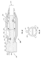
- FIG. 1A shows a side schematic view of a catheter according to a first embodiment of the invention.
- FIG. 1B shows a cross-sectional view of the catheter of FIG. 1A , as indicated by lines 1 B— 1 B in FIG. 1 A.
- FIG. 1C shows an alternate cross-sectional view of the catheter of FIG. 1A , as indicated by lines 1 B— 1 B in FIG. 1 A.
- FIG. 2A shows a side schematic view of a catheter according to a second embodiment of the invention.
- FIG. 2B shows a cross-sectional view of the catheter of FIG. 2A , as indicated by lines 2 B— 2 B in FIG. 2 A.
- FIG. 3 shows a schematic view of a catheter in use according to a third embodiment of the invention.
- FIG. 4 shows a cross-sectional view of the catheter of FIG. 3 .
- FIG. 5 shows an alternative cross-sectional view of the catheter of FIG. 3 .
- FIG. 6 shows an alternative cross-sectional view of the catheter of FIG. 3 .
- FIG. 7 shows a schematic view of the warm balloon of the catheter of FIG. 3 .
- FIG. 8 shows a side schematic view of a catheter according to a fourth embodiment of the invention, this embodiment employing a porous balloon.
- FIG. 9 shows a side schematic view of a catheter according to a fifth embodiment of the invention, this embodiment employing a porous balloon.
- FIG. 10 shows a first embodiment of a device that may be employed in the present invention to prevent tissue damage at, e.g., the point of catheter insertion into the patient's body.
- FIG. 11 shows a second embodiment of a device that may be employed in the present invention to prevent tissue damage at, e.g., the point of catheter insertion into the patient's body.
- FIG. 12 shows a third embodiment of a device that may be employed in the present invention to prevent tissue damage at, e.g., the point of catheter insertion into the patient's body.
- FIG. 13 shows a first embodiment of a device that may be employed in the present invention to prevent tissue damage at, e.g., the atrial septum.
- FIG. 14 shows a second embodiment of a device that may be employed in the present invention to prevent tissue damage at, e.g., the atrial septum.
- FIG. 15 shows an embodiment of a device that may be employed in the present invention to perform cryoablation while allowing blood flow during an ablation procedure.
- FIGS. 16 and 17 show more detailed views of the embodiment of FIG. 15 .
- FIG. 18 shows a flowchart of a method for pre-outgassing a fluid.
- a catheter 100 is shown according to a first embodiment of the invention.
- the catheter 100 has a proximal end 130 and a distal end 114 .
- this figure is not necessarily to scale and in general use the proximal end 130 is far upstream of the features shown in FIG. 1 A.
- the catheter 100 may be used within a guide catheter 102 , and generally includes an outer tube 103 , a dual balloon 134 , and an inner tube 122 . These parts will be discussed in turn.
- the guide catheter 102 provides a tool to dispose the catheter 100 adjacent the desired location for, e.g., angioplasty or reduction of atrial fibrillation.
- Typical guide catheter diameters may be about 6 French to 9 French, and the same may be made of polyether blockamide, polyamides, polyurethanes, and other similar materials.
- the distal end of the guide catheter is generally adjacent the proximal end of the dual balloon 134 , and further is generally adjacent the distal end of the outer tube 103 .
- the ability to place the guide catheter is a significant factor in the size of the device.
- a suitably sized guide catheter must be used. This restricts the size of the catheter 100 that may be disposed within the guide catheter. A typical diameter of the catheter 100 may then be about 7 French or less or about 65 to 91 mils.
- a catheter for use in the coronary arteries is described. Of course, which catheter is used in which artery is a matter to be determined by the physician, taking into account such factors as the size of the individual patient's affected arteries, etc.
- the outer tube 103 houses the catheter 100 while the latter traverses the length of the guide catheter 102 .
- the outer tube 103 may have a diameter of about 4 French to 7 French, and the same may be made of polyether blockamide, poly-butylene terephtalate, polyurethane, polyamide, polyacetal polysulfone, polyethylene, ethylene tetrafluoroethylene, and other similar materials.
- the distal end of the outer tube 103 adjoins the proximal end of the dual balloon 134 .
- the outer tube 103 provides a convenient location for mounting a proximal end of an outer balloon 104 within the dual balloon 134 , and further may provide an inlet 128 for providing a fluid such as a liquid to a first interior volume 106 between the dual balloons.
- an inlet 128 per se may not be necessary: the fluid, which may also be a sub-atmospheric level of gas or air, may be provided during manufacture in the first interior volume 106 .
- the proximal and distal ends of the first interior volume may be sealed during manufacture.
- the inlet 128 may be at least partially defined by the annular volume between the interior of the outer tube 103 and the exterior of the inner tube 122 .
- the dual balloon 134 includes an outer balloon 104 and an inner balloon 108 . Between the two is the first interior volume 106 .
- the outer balloon 104 may be inflated by inflating the interior volume 106 .
- the inner balloon 108 has a second interior volume 110 associated with the same.
- the inner balloon 108 may be inflated by inflating the second interior volume 110 .
- both the inner balloon 108 and the outer balloon 104 may be inflated using biocompatible liquids, such as Galden® fluid, perfluorocarbon-based liquids, or various contrast agents. Fluids such as DMSO, d-limonene, and the like may also be employed. There is no need that the fluid inflating one of the interior volumes be the same fluid as that inflating the other. Additional details on these fluids are described below.
- this fluid may be, e.g., stationary or static: in other words, it need not be circulated.
- this fluid would in general be circulated by an external chiller (not shown).
- the chiller may be, e.g., a gear pump, peristaltic pump, etc. It may be preferable to use a gear pump over a peristaltic pump as the attainable pressure of the former is generally greater than that of the latter.
- gear pumps have the advantageous property of being linear, i.e., their output varies in direction proportion with their revolutions per minute. Two types of gear pumps which may be employed include radial spur gear pumps and helical tooth gear pumps.
- the helical tooth gear pump may be more preferable as the same has been associated with higher pressures and a more constant output.
- the ability to achieve high pressures may be important as the cooling fluid is required to pass through a fairly narrow, e.g., five to seven French, catheter at a certain rate.
- the viscosity of the fluid, at the low temperatures should be appropriately low. In this way, e.g., the flow may be increased.
- an appropriate type of fluid may be Galden® fluid, and in particular Galden® fluid item number “HT-55”, available from Ausimont Inc. of Thorofare, N.J.
- this fluid has a viscosity of 2.1 centiStokes.
- At ⁇ 70° C. this fluid has a viscosity of 3.8 centiStokes. It is believed that fluids with such viscosities at these temperatures would be appropriate for use.
- perfluorocarbon fluids such as Galden fluid and d-limonene
- Galden fluid and d-limonene may be known to outgas the dissolved nitrogen, oxygen, etc., if injected into the systemic circulation, despite their being otherwise biocompatible. Such outgassing has deleterious consequences.
- a procedure may be employed to void the fluids of dissolved gases.
- the procedure may also be employed on non-outgassing fluids, without damaging the fluid, this feature allowing a single circulation to be employed for numerous types of fluids. This method is shown in FIG. 18 .
- a fluid to be treated is introduced into a vessel in which a vacuum can be achieved (step 802 ).
- This, or any of the other steps, may either be done as a pre-treatment for fluid to be used as a circulating fluid or can be done within a circulating fluid console to “on-the-fly” treatment.
- the fluid is then placed in a location where the same may be stirred, such as on a magnetic stir plate (step 804 ).
- a reasonably pure grade, USP or better, of helium is then diffused into and through the fluid for a period of time, such as 20-30 minutes, while the fluid is stirred, e.g., with a Teflon-coated stir bar (step 806 ).
- the fluid diffusion may be stopped, and a vacuum pulled on the fluid for a second period of time, e.g., 5 minutes, while the fluid is being optionally at least slightly stirred.
- the fluid may then be ready for use.
- the fluid degassing process may be done in line and continuously with the circulation process.
- An in-line sensor may be used, with an alarm, to ensure that the fluid is void of any dissolved gases and is safe for use.
- the so-called “cones” of the balloons 108 and 104 may be made somewhat thicker than the remainder of the balloon sections. In this way, the heat transfer efficiency in these sections is significantly less than over the remainder of the balloon sections, this “remainder” effectively defining a “working region” of the balloon. In this way, the cooling or “cryoplasty” may be efficiently localized to the affected area rather than spread over the length of the balloon.
- the inner tube 122 is disposed within the interior of the dual balloon 134 and within the interior of the guide catheter 102 .
- the inner tube 122 includes a supply lumen 120 , a return lumen 118 , and a guidewire lumen 116 .
- the guidewire lumen 116 may have sizes of, e.g., 17 or 21 mils inner diameter, in order to accommodate current standard sized guidewires, such as those having an outer diameter of 14 mils. This structure may be preferable, as the pressure drop encountered may be substantially less.
- the supply lumen 120 may be used to supply a circulating liquid to the second interior volume 110 .
- the return lumen 118 may be used to exhaust the circulating liquid from the second interior volume to the external chiller. As may be seen from FIG.
- both lumens 118 and 120 may terminate prior to the distal end 114 of the catheter 100 .
- the lumen arrangement may be seen more clearly in FIG. 1 B.
- FIG. 1C shows an alternate such arrangement, and one that may provide an even better design for minimal pressure drop.
- lumens 118 ′ and 120 ′ are asymmetric about guidewire lumen 116 ′.
- a set of radio opaque marker bands 112 may be disposed on the inner tube 122 at locations substantially adjacent the cones 132 to define a central portion of the “working region” of the balloons 104 and 108 . This working region is where the “cryoplasty” procedures described below may substantially occur.
- the proximal portion of the outer balloon 104 is mounted on the outer tube 103 at its distal end.
- the distal end of the outer balloon 104 is secured to the distal end of the catheter 100 and along the inner tube 122 .
- both the proximal and distal ends of the inner balloon 108 may be secured to the inner tube 122 to create a sealed second interior volume 110 .
- At least two skives 124 and 126 may be defined by the inner tube 122 and employed to allow the working fluid to exit into the second interior volume 110 and to exhaust the same from the second interior volume 10 .
- the skive 124 is in fluid communication with the lumen 120 and the skive 126 is in fluid communication with the lumen 118 .
- fluid communication refers to a relationship between two vessels where a fluid pressure may cause a net amount of fluid to flow from one vessel to the other.
- the skives may be formed by known techniques.
- a suitable size for the skives may be from about 50 mils to 125 mils.
- a plurality of optional tabs 119 may be employed to roughly or substantially center the inner tube 122 within the catheter 100 .
- These tabs may have the shape shown, the shape of rectangular or triangular solids, or other such shapes so long as the flow of working fluid is not unduly impeded.
- the phrase “the flow of working fluid is not unduly impeded” is essentially equated to the phrase “substantially center”.
- the tabs 119 may be made of polyether blockamide, poly-butylene terephtalate, polyurethane, polyamide, polyacetal polysulfone, polyethylene, ethylene tetrafluoroethylene, and other similar materials, and may have general dimensions of from about 3 mils to 10 mils in height, and by about 10 mils to 20 mils in width.
- the guide catheter 102 may be inserted into an affected artery or vein such that the distal tip of the guide catheter is just proximal to an affected area such as a calcified area or lesion.
- an affected area such as a calcified area or lesion.
- This step provides a coarse estimate of proper positioning, and may include the use of fluoroscopy.
- the guide catheter may be placed using a guide wire (not shown). Both the guide catheter and guide wire may already be in place as it may be presumed a balloon angioplasty or stent placement has previously been performed.
- the catheter 100 may then be inserted over the guide wire via the lumen 116 and through the guide catheter 102 .
- both a guide wire and a guide catheter are not strictly necessary—one or the other may often suffice.
- the dual balloon 134 may be uninflated to maintain a minimum profile. In fact, a slight vacuum may be drawn to further decrease the size of the dual balloon 134 so long as the structural integrity of the dual balloon 134 is not thereby compromised.
- a fine positioning step may occur by way of the radio opaque marker bands 112 .
- the location of the radio opaque marker bands 112 can be identified in relation to the location of the lesion.
- the catheter may be advantageously placed at the location of the lesion and further such that the lesion is between the two marker bands. In this way, the working region of the balloon 134 will substantially overlap the affected area, i.e., the area of the lesion.
- a biocompatible heat transfer fluid which may also contain contrast media, may be infused into the first interior volume 106 through the inlet 128 . While the use of contrast media is not required, its use may allow early detection of a break in the balloon 104 because the contrast media may be seen via fluoroscopy to flow throughout the patient's vasculature.
- a biocompatible cooling fluid may be circulated through the supply lumen 120 and the return lumen 118 . Before or during the procedure, the temperature of the biocompatible cooling fluid may be lowered to a therapeutic temperature, e.g., between ⁇ 40° C. and ⁇ 60° C., although the exact temperature required depends on the nature of the affected area.
- the fluid exits the supply lumen 120 through the skive 124 and returns to the chiller through the skive 126 and via the return lumen 118 . It is understood that the respective skive functions may also be reversed without departing from the scope of the invention.
- the biocompatible cooling fluid in the second interior volume 110 chills the biocompatible heat transfer fluid within the first interior volume 106 to a therapeutic temperature of, e.g., between about ⁇ 25° C. and ⁇ 50° C.
- the chilled heat transfer fluid transfers thermal energy through the wall of the balloon 104 and into the adjacent intimal vascular tissue for an appropriate therapeutic length of time. This time may be, e.g., about 1 ⁇ 2 to 4 minutes.
- the circulation of the biocompatible cooling fluid may cease.
- the heat transfer fluid within the first interior volume 106 may be withdrawn though the inlet 128 .
- the balloons 104 and 108 may be collapsed by pulling a soft vacuum through any or all of the lumens 124 , 126 , and 128 .
- the catheter 100 may be withdrawn from the treatment site and from the patient through the guide catheter 102 .
- Substantially the same catheter may be used to treat atrial fibrillation.
- the catheter is inflated as above once it is in location.
- the location chosen for treatment of atrial fibrillation is such that the working region spans a portion of the left atrium and a portion of the affected pulmonary vein.
- the working region of the catheter may have a length of about 5 mm to 30 mm.
- the affected pulmonary vein, of the four possible pulmonary veins, which enter the left atrium, may be determined by electrophysiology studies.
- a catheter with a needle point may first be inserted at the femoral vein and routed up to the right atrium.
- the needle of the catheter may then be poked through the interatrial septum and into the left atrium.
- the catheter may then be removed if desired and a guide catheter disposed in the same location.
- a guide wire may be used through the guide catheter and may be maneuvered at least partially into the pulmonary vein.
- a catheter such as the catheter 100 may be placed in the volume defining the intersection of the pulmonary vein and the left atrium.
- a method of use similar to that disclosed above is then employed to cool at least a portion of, and preferably all of, the circumferential tissue.
- the coldness of the balloon assists in the adherence of the circumferential tissue to the balloon, this feature serving to increase the overall heat transfer rate.
- the catheter 100 above may be particularly useful for procedures in the carotid arteries by virtue of its size.
- an even smaller catheter may be desired.
- one with an outer diameter less than 5 French may be desired.
- a catheter 200 is shown according to a second embodiment of the invention. This embodiment may be particularly useful for use in the coronary arteries because the dimensions of the catheter 200 may be considerably smaller than the dimensions of the catheter 100 .
- the catheter 200 is similar to the above-described catheter 100 .
- the catheter 200 has a proximal end 230 and a distal end 214 and may be used within a guide catheter 202 .
- the catheter 200 includes an outer tube 203 , a dual balloon 234 , and an inner tube 222 .
- the ability to place the guide catheter is a significant factor in the size of the device.
- a suitably sized guide catheter may be used to perform angioplasty in the coronary arteries. This then restricts the size of the catheter 200 which may be disposed within the guide catheter.
- a typical diameter of the catheter 200 may then be about 3 French or less or about 35-39 mils. The same may be placed in the femoral artery in order to be able to track to the coronary arteries in a known manner.
- the outer tube 203 houses the catheter 200 and may have an outside diameter of about 5 French to 7 French, and the same may be made of similar materials.
- the distal end of the outer tube 203 adjoins the proximal end of the dual balloon 234 .
- the outer tube 203 provides a mounting location for an outer balloon 204 , and further provides an inlet 228 for providing a fluid such as a liquid to a first interior volume 206 between the dual balloons.
- an inlet 228 per se may not be necessary: the fluid, which may also be a sub-atmospheric level of air, may be provided in the first interior volume 206 .
- the proximal and distal ends of the volume may be sealed during manufacture.
- the inlet 228 may be at least partially defined by the annular volume between the interior of the outer tube 203 and the exterior of the inner tube 222 .
- the dual balloon 234 includes an outer balloon 204 and an inner balloon 208 . These balloons are basically similar to balloons 104 and 108 described above, but may be made even smaller for use in the smaller coronary arteries.
- the same types of fluids may be used as in the catheter 100 .
- the inner tube 222 is disposed within the interior of the dual balloon 234 and within the interior of the guide catheter 202 .
- the inner tube 222 includes a supply lumen 220 and a return lumen 218 .
- a set of radio opaque marker bands 212 may be disposed on the inner tube 222 for the same reasons disclosed above in connection with the marker bands 112 .
- the proximal portion of the outer balloon 204 is mounted on the outer tube 203 at its distal end.
- the distal end of the outer balloon 204 is secured to the distal end of the catheter 200 and along the inner tube 222 .
- both the proximal and distal ends of the inner balloon 208 may be secured to the inner tube 222 to create a sealed second interior volume 210 .
- At least two skives 224 and 226 may be defined by the inner tube 222 and employed to allow the working fluid to exit into the second interior volume 210 and to exhaust the same from the second interior volume 210 .
- a plurality of optional tabs 219 may be employed to roughly or substantially center the inner tube 222 within the catheter 200 as in catheter 100 .
- These tabs may have the same general geometry and design as tabs 119 . Of course, they may also be appropriately smaller to accommodate the smaller dimensions of this coronary artery design.
- the tabs 119 and 219 are particularly important in the catheters 100 and 200 , as contact by the inner tube of the outer tube may also be associated with an undesired conductive heat transfer prior to the working fluid reaching the working region, thereby deleteriously increasing the temperature of the working fluid at the working region.
- the method of use of the catheter 200 is generally the same as for the catheter 100 .
- Known techniques may be employed to place the catheter 200 into an affected coronary artery.
- an external guidewire may be used with appropriate attachments to the catheter.
- FIG. 3 an alternative embodiment of a catheter 300 which may be employed in PV ablation is detailed.
- a dual balloon system 301 is shown; however, the balloons are not one within the other as in FIG. 1 .
- a warm balloon 302 is distal of a cold balloon 304 .
- Warm balloon 302 may be used to anchor the system 301 against movements, which may be particularly useful within a beating heart.
- Cold balloon 304 may then be employed to cryo-ablate a circumferential lesion at the point where a pulmonary vein 306 enters the left atrium 308 .
- a working fluid may be introduced via an outlet port 308 and may be retrieved via an inlet port 310 .
- Ports 308 and 310 may be skived in known fashion into the catheter shaft lumens whose design is exemplified below.
- the warm balloon 302 serves to anchor the system 301 in the pulmonary vein and left atrium.
- the warm balloon 302 also serves to stop blood, which is traveling in the direction indicated by arrow 312 , from freezing upon contact with the cold balloon 304 . In this way, the warm balloon 302 acts as an insulator to cold balloon 304 .
- the warm balloon 302 may be served by only one skived port, or by two ports, such as an inlet port 314 and an outlet port 316 , as shown in FIG. 3 .
- a separate lumen or lumens may be used to fill the warm balloon.
- a valve mechanism may be used to fill the warm balloon using fluid from the cold balloon. In the case where only one port is used to fill the warm balloon, draining the same requires a slight vacuum or negative pressure to be placed on the lumen servicing the inlet/outlet port.
- a benefit to the two lumen design is that the warm balloon may be inflated and deflated in a more expeditious manner.
- Typical pressures within the warm balloon may be about 1-2 atm (10-30 psi), and thus maintains a fairly low pressure.
- An appropriate fluid will be biocompatible, and may be Galden fluid, D5W, and so on.
- Typical pressures within the cold balloon may be about 5-7 atm, for example about 6 atm (e.g., at about 100 psi), and thus maintains a higher pressure.
- An appropriate fluid may be Galden fluid, e.g., HT-55, D5W, and so on.
- the volume of fluid required to fill the cold balloon may vary, but may be about 4-8 cc.
- the cold balloon may be about 2 to 21 ⁇ 2 cm long, and have a diameter of 1 to 21 ⁇ 2 cm.
- the warm balloon may be glued or otherwise attached to the cold balloon.
- draining both balloons may simply entail closing either the return lumen or the supply lumen, and drawing a vacuum on the other. In this way, both the cold and warm balloons may be evacuated.
- a standard medical “indeflator” may be used to pressurize and de-pressurize the various lumens and balloons.
- FIG. 4 shows an embodiment of the arrangement of lumens within the catheter.
- supply and return lumens for the cold balloon 304 are shown by lumens 318 and 320 , respectively.
- Supply and return lumens for the warm balloon 302 are shown by lumens 322 and 324 , respectively, although as noted only one may be used as required by the dictates of the user.
- a guidewire lumen 326 is also shown.
- An alternative arrangement is shown in FIG. 5 , where the corresponding lumens are shown by primes.
- the exterior blood is exposed to the cold supply flow.
- FIG. 6 an alternative lumen design is shown in which the cold fluid supply lumen 328 is exposed to only the cold fluid return lumen 330 .
- An insulation space 332 may also be employed. In this way, the heat flux from the exterior flow is minimized and the cold fluid may reach the cold balloon at a lower temperature.
- One drawback to such a system is that the operational pressure may be higher.
- the overall catheter outer diameter may be about 0.130′′, e.g. about 10 French, including an insulation sleeve and guide discussed below.
- the catheter shaft 303 itself may be about 0.110′′ and may be made of, e.g., polyethylene (PE), and preferably a combination of a low density PE and a high density PE.
- the inlet and outlet ports or inlet/outlet port of the warm balloon may be skived from the lumens 322 and 324 .
- the warm balloon 302 itself may be made of a sleeve 332 of silicone tubing of, e.g., 35 durometer on the “D” scale, and held in place by two pieces of PET heat shrink tubing 334 .
- Alternative methods of securing the warm balloon during inflation may include metal bands or an adhesive.
- marker bands 336 may be employed within either or both of the cold balloon and warm balloon to assist the physician is disposing the same in an appropriate location.
- the marker bands typically denote the working areas of the balloons, and may be made of Pt, Iridium, Au, etc.
- the working cold fluid may exit the circulation system or chiller at, e.g., about ⁇ 85° C.
- the circulation system or chiller may be, e.g., a two-stage heat exchanger.
- the fluid may then enter the catheter at about ⁇ 70° C. to about ⁇ 75° C., and may strike the balloon at about ⁇ 55° C. to about ⁇ 65° C.
- the overall procedure may take less than a minute to circumferentially ablate the desired tissue up to several minutes.
- these numbers are only exemplary and the same depend on the design of the system and fluids used.
- Mapping electrodes 338 may be employed at the distal end of the warm balloon. These mapping electrodes may each have a wire attached, the wires extending down, e.g., the supply and return lumens for the warm fluid or the cold fluid. The mapping electrodes 338 may be used to detect stray electrical fields to determine where ablation may be needed and/or whether the ablation procedure was successful. The mapping electrodes may typically be about 2-3 mm apart from each other.
- the warm balloon typically involves adhering the same to the shaft 303 and skiving the inlet and outlet ports.
- the silicone sleeve 340 may then serve to further insulate the non-working sections of the balloons from blood that would otherwise potentially freeze during a procedure.
- the silicone sleeve would typically be attached only at a portion of its length, such as that indicated by circle 342 , so that the same may slide along the balloon as the balloon is inflated.
- the silicone sleeve also serves to assist in collapsing the balloon during deflation.
- the entire catheter shaft 303 may be surrounded by an insulation catheter sleeve 344 (see FIG. 4 ).
- Sleeve 344 may have a thickness of, e.g., 0.01 inches, and may be made of a foamed extrusion, e.g., that with voids of air disposed within. The voids further assist the insulating effect since their heat transfer is extremely low. A void to polymer ratio of, e.g., 20% to 30% may be particularly appropriate.
- foamed extrusions are available from, e.g., Applied Medical Resources in Website, Calif., or Extrusioneering, Inc., in Temecula, Calif.
- an insulation sleeve may be used as noted above.
- the warm balloon may be omitted, and only the therapeutic cold balloon used.
- the therapeutic cold balloon may be employed as a single balloon system without the use of tabs. Such a system may be particularly convenient to manufacture and install.
- the invention may employ a porous or microporous balloon to enhance heat transfer between the working fluid and the tissue to be treated.
- a catheter 400 is shown according to a first embodiment of the invention.
- the catheter 400 has a proximal end 430 and a distal end 414 .
- the catheter 400 may be used within a guide catheter 402 , and generally includes an outer tube 403 , a dual balloon 434 , and an inner tube 422 . These parts will be discussed in turn.
- the guide catheter 402 may be similar to that discussed above in connection with FIG. 1 .
- the outer tube 403 houses the catheter 400 while the latter traverses the length of the guide catheter 402 .
- the outer tube 403 may have a diameter of about 4 French to 7 French, and the same may be made of polyether blockamide, poly-butylene terephtalate, polyurethane, polyamide, polyacetal polysulfone, polyethylene, ethylene tetrafluoroethylene, and other similar materials.
- the distal end of the outer tube 403 adjoins the proximal end of the dual balloon 434 .
- the outer tube 403 provides a convenient location for mounting a proximal end of an outer balloon 404 within the dual balloon 434 , and further may provide an inlet 428 -for providing a fluid such as a liquid to a first interior volume 406 between the dual balloons.
- an inlet 428 per se may not be necessary: the fluid, which may also be a sub-atmospheric level of gas or air, may be provided during manufacture in the first interior volume 406 .
- the proximal and distal ends of the first interior volume may be sealed during manufacture.
- the pressure of inflation would then provide the force necessary to cause the fluid within the first interior volume to at least partially “leak” to the tissue.
- the inlet 428 may be at least partially defined by the annular volume between the interior of the outer tube 403 and the exterior of the inner tube 422 .
- the dual balloon 434 includes an outer balloon 404 and an inner balloon 408 . Between the two is the first interior volume 406 .
- the outer balloon 404 may be inflated by inflating the interior volume 406 .
- the inner balloon 408 has a second interior volume 410 associated with the same.
- the inner balloon 408 may be inflated by inflating the second interior volume 410 .
- both the inner balloon 408 and the outer balloon 404 may be inflated using biocompatible liquids, such as Galden® fluid, perfluorocarbon-based liquids, or various contrast agents. There is no need that the fluid inflating one of the interior volumes be the same fluid as that inflating the other. Additional details on these fluids were described above.
- this fluid may be, e.g., stationary or static: in other words, it need not be circulated.
- this fluid would in general be circulated by an external chiller (not shown).
- the chiller may be, e.g., a gear pump, peristaltic pump, etc. It may be preferable to use a gear pump over a peristaltic pump for the reasons described above.
- the inner tube 422 is disposed within the interior of the dual balloon 434 and within the interior of the guide catheter 402 .
- the inner tube 422 includes a supply lumen 420 , a return lumen 418 , and a guidewire lumen 416 .
- the guidewire lumen 416 may have sizes of, e.g., 17 or 21 mils inner diameter, in order to accommodate current standard sized guidewires, such as those having an outer diameter of 14 mils. This structure may be preferable as described above.
- the return lumen 418 may be used to exhaust the circulating liquid from the second interior volume to the external chiller. As may be seen from FIG. 8 , both lumens 418 and 420 may terminate prior to the distal end 414 of the catheter 400 .
- the lumen arrangement may be similar to that of FIGS. 1B or 1 C.
- a set of radio opaque marker bands 412 may be disposed on the inner tube 422 at locations substantially adjacent the cones 432 to define a central portion of the “working region” of the balloons 404 and 408 .
- the proximal portion of the outer balloon 404 is mounted on the outer tube 403 at its distal end.
- the distal end of the outer balloon 404 is secured to the distal end of the catheter 400 and along the inner tube 422 .
- both the proximal and distal ends of the inner balloon 408 may be secured to the inner tube 422 to create a sealed second interior volume 410 .
- At least two skives 424 and 426 may be defined by the inner tube 422 and employed to allow the working fluid to exit into the second interior volume 410 and to exhaust the same from the second interior volume.
- the skive 424 is in fluid communication with the lumen 420 and the skive 426 is in fluid communication with the lumen 418 .
- fluid communication refers to a relationship between two vessels where a fluid pressure may cause a net amount of fluid to flow from one vessel to the other.
- the skives may be formed by known techniques.
- a suitable size for the skives may be from about 50 mils to 125 mils.
- At least one pore 415 may be provided within the outer balloon 404 . In this way, a portion of the fluid within the first interior volume 406 may leak to the exterior of the outer balloon 404 , contacting the tissue and providing enhanced heat transfer, due to conduction, between the fluid and the tissue to be treated.
- a porous or microporous balloon is known, and either may be employed in this application.
- Such balloons are alternatively known as “weeping” balloons.
- pore sizes can be controlled at least to the micron range. The pore size determines the rate of release of the fluid.
- a conflicting requirement is that the balloon must be inflated and deployed, this requirement having the effect that the balloon must be strong and at least about 1-2 atmospheres of pressure must be maintained in the balloon.
- the pores can be designed to be placed in a band, so as to only leak at about where the circumferential region of tissue is located.
- the pores can be placed in a helix, spiral, e.g., relative to an axis 401 of the catheter, or other such shape as dictated by the demands of the user. Only one pore may be used in applications where only a minimum of enhanced conductivity is required.
- the guide catheter 402 may be inserted into an affected artery or vein such that the distal tip of the guide catheter is just proximal to an affected area such as a calcified area or lesion.
- the catheter 400 may then be inserted over the guide wire via the lumen 416 and through the guide catheter 402 .
- both a guide wire and a guide catheter are not strictly necessary—one or the other may often suffice.
- the dual balloon 434 may be uninflated to maintain a minimum profile. In fact, a slight vacuum may be drawn to further decrease the size of the dual balloon 434 so long as the structural integrity of the dual balloon 434 is not thereby compromised.
- a biocompatible heat transfer fluid which may also contain contrast media, may be infused into the first interior volume 406 through the inlet 428 . This fluid then begins to leak via pores 415 , flowing between the balloon and the tissue to be treated and enhancing the conductive heat transfer between the two.
- the biocompatible cooling fluid may then be circulated through the supply lumen 420 and the return lumen 418 .
- the fluid exits the supply lumen 420 through the skive 424 and returns to the chiller through the skive 426 and via the return lumen 418 .
- the respective skive functions may also be reversed without departing from the scope and spirit of the invention.
- the circulation of the biocompatible cooling fluid may cease.
- the remaining heat transfer fluid within the first interior volume 406 may be withdrawn though the inlet 428 .
- the balloons 404 and 408 may be collapsed by pulling a soft vacuum through any or all of the lumens 424 , 426 , and 428 .
- the catheter 400 may be withdrawn from the treatment site and from the patient through the guide catheter 402 .
- FIG. 9 an alternative embodiment of a catheter which may be employed in PV ablation is detailed.
- a dual balloon system 501 is shown which is similar to the embodiment of FIG. 3 .
- warm balloon 502 may be used to anchor the system 501 against movements, while cold balloon 504 may be employed to cryo-ablate a circumferential lesion at the point where a pulmonary vein 506 enters the left atrium 508 .
- a working fluid may be introduced via an outlet port 508 and may be retrieved via an inlet port 510 .
- Ports 508 and 510 may be skived in known fashion into the catheter shaft lumens whose design is exemplified below.
- the cold balloon 504 may be a porous or microporous balloon, having pores as indicated in FIG. 9 by pores 515 .
- the warm balloon 502 serves to anchor the system 501 in the pulmonary vein and left atrium.
- the warm balloon 502 also serves to stop blood, which is traveling in the direction indicated by arrow 512 , from freezing upon contact with the cold balloon 504 . In this way, the warm balloon 502 acts as an insulator to cold balloon 504 .
- the warm balloon 502 may be served by only one skived port, or by two ports, such as an inlet port 514 and an outlet port 516 , as shown in FIG. 9 .
- a separate lumen or lumens may be used to fill the warm balloon.
- a valve mechanism may be used to fill the warm balloon using fluid from the cold balloon. In the case where only one port is used to fill the warm balloon, draining the same requires a slight vacuum or negative pressure to be placed on the lumen servicing the inlet/outlet port.
- Typical pressures within the warm balloon may be as above. Typical pressures within the porous cold balloon may be about 1-2 atm, for example about 1.5 atm.
- An appropriate cryogenic fluid may be Galden fluid, e.g., HT-55, or others with similar properties.
- the volume of fluid required to fill the cold balloon may vary, but may be about 4-8 cc.
- the cold balloon may be about 2 to 21 ⁇ 2 cm long, and have a diameter of 1 to 4 cm.
- a porous or microporous balloon may also be employed in an application in which the above or similar balloons are employed to treat restenosis.
- the angioplasty balloon may be removed while the guidewire left in place.
- the balloon may be delivered up to the location of treatment via the guidewire, and operated for a minute, or other appropriate time as determined by, e.g., the physician.
- the outer diameter of the catheter would typically be less than about 6 French, as the same would require compatibility with existing coronary angioplasty hardware, such as a 9 French guide catheter.
- a device 701 which may be employed for treatment of atrial fibrillation by circumferential ablation, while allowing blood flow to continue, thereby reducing, minimizing, or eliminating the risk of stroke during long cryoablation procedures.
- an annular ring balloon 706 having a toroidal shape is fluidically coupled to a catheter shaft 708 near the distal end 714 thereof.
- the annular ring balloon 706 may be inflated by any of the various fluids described elsewhere in this specification, and may further cause the cryoablation of a circumferential region of tissue at a location where the pulmonary vein 704 meets the left atrium 718 , i.e., the ostium of the pulmonary vein. Blood flow is then only minimally impeded as the same flows between location A and location B.
- the diameter of the interior annulus may be appropriately sized to accomplish this objective.
- a supply lumen 712 also termed a catheter supply lumen, provides the cryoablation fluid to an interior of the annular ring balloon 706 to inflate the same.
- a roughly annular portion 702 of the shaft 708 surrounding the supply lumen 712 serves as a catheter return lumen for return of the cryoablation fluid to exhaust the balloon.
- Fluid inlet 720 may be offset, in the direction of the axis of shaft 708 , from fluid outlet 722 .
- the fluid inlet 720 may be slightly proximal of the fluid outlet 722 . This accomplishes a greater ease in trackability of the uninflated device, as well as more convenient manufacturability.
- the radius of expansion should be sufficient to enable overlap 710 at the point where the balloon is coupled to the shaft, so as to ensure a contiguous cryo-ablation injury, but not so great as to impede the blood flow. A view even better showing this is shown in FIG. 17 .
- FIGS. 15-17 may further be employed for angioplasty procedures, as will be realized given the teaching above.
- the annular ring balloon may be manufactured in a way similar to current balloons. It may be a basic cylinder with tapered ends that mate with the catheter shaft. The plane of the balloon is normal to the catheter shaft. This concept is different from centering balloons in a number of ways, which typically are designed to enable blood flow between the vascular wall and the balloon. It may also be distinct from coronary perfusion catheters that are designed to re-route blood flow through the catheter shaft.
- the outer diameter of the toroidal annular ring balloon may be about 1 cm.
- the supply lumen extends throughout the annular ring balloon.
- This is then termed a balloon supply lumen and the same is indicated in FIG. 16 by dotted lines showing balloon supply lumen 721 and balloon return lumen 723 .
- the annular ring balloon itself is biaxial, having a balloon supply and balloon return lumen within.
- the balloon return lumen which is generally warmer, may be disposed towards the inner radius of the balloon, adjacent to which the blood is flowing.
- the balloon supply lumen may be disposed towards the outer radius of the balloon, where the cryo-ablation is to occur.
- tissue may be thermally damaged unintentionally.
- tissue may be thermally damaged unintentionally.
- relatively constant contact of the tubing with the tissue may lead to thermal damage.
- tubing penetrates the atrial septum, in atrial fibrillation situations.
- one or a combination of the below embodiments may be employed.
- insulating or warming the affected regions is performed via modifying a portion or more of the full-length introducer or sheath that houses the catheter from the site of insertion into the left atrium.
- Introducer or introducer sheath 600 that prevents freezing around the site of the percutaneous insertion.
- Introducer or introducer sheath 600 generally has an introducer tube 606 at a distal end and a hub 604 at a proximal end.
- a catheter 608 for cryoablation may be seen in schematic form emerging from the distal end of the introducer tube 606 .
- Warmed fluid such as injection grade saline, is introduced via an optional insertion tube 602 to the hub 604 . This fluid traverses the annular region 610 between an exterior wall of the catheter shaft 608 and an interior wall of the introducer tube 606 .
- the fluid loses heat to the catheter, becoming cooled in the process, and exits the interior of the introducer of sheath 600 via outlet ports 612 .
- These outlet ports are positioned on the introducer is such a way as to exhaust the cooled fluid directly into venous blood. Forced convection of the fluid between the catheter shaft and the introducer prevents the temperature on the exterior of the introducer from falling to dangerous levels, such as near freezing.
- a resistive heater may be employed.
- an embodiment of an introducer or sheath 600 ′ is shown that prevents freezing around the site of the percutaneous insertion.
- Introducer or sheath 600 ′ generally has an introducer tube 606 ′ at a distal end and a hub 604 ′ at a proximal end.
- a catheter 608 for cryoablation may be seen in schematic form emerging from the distal end of the introducer tube 606 ′.
- a resistive heater 614 is wound around the introducer tube 606 ′ and is conductively coupled to wires 616 leading to control unit 618 .
- the heater 614 may be in the form of a helical wire or strip, applied to the exterior of the introducer tube 606 ′, and of sufficient length so as to extend into the accessed vein.
- the heater may be characterized in such a way that the resistance is a function of temperature.
- An external power source and control unit 618 may be employed to maintain the temperature of the heating coil 614 at the desired value, preferably nominal body temperature (37° C.), thus preventing thermal damage to adjacent tissue.
- the external power source and control unit may be within one or two or more separate physical units.
- the helical form of coil 614 may be preferred; however, various other geometries of resistive heaters may also be used.
- FIG. 12 another embodiment 600 ′′ is shown that prevents freezing of tissue around the site of percutaneous insertion.
- a resistive heater 622 in the form of a helical wire or strip is applied to the exterior of a sleeve 620 which fits tightly over and yet is free to move on the exterior surface of the introducer 606 ′′.
- the sleeve 620 is positioned so as to encompass the tissue between the insertion site and the interior of the accessed vein.
- An external power source and control circuit which may be similar to that employed in FIG. 11 , are employed to maintain the temperature of the heating coil 622 at the desired value, preferably nominal body temperature (37° C.), thus preventing thermal damage to adjacent tissue.
- the helical form while preferred, is not the only geometry of resistive heater to which this disclosure may apply.
- the location of percutaneous insertion is not the only location at which tissue damage may occur. For example, damage may also occur at the atrial septum or other locations where the device may rest against tissue for periods of time.
- a resistive heater 626 in the form of a helical wire or strip is applied to the exterior of the introducer 632 near the distal tip 624 , so that the length of the heater 626 encompasses the entire path of the introducer 632 through the atrial septum 628 .
- an external power source and control circuit are employed to maintain the temperature of the heating coil at the desired value, preferably nominal body temperature (37° C.), thus preventing thermal damage to adjacent tissue.
- the helical form while preferred, is not the only geometry of resistive heater to which this disclosure may apply.
- FIG. 14 another embodiment is shown that prevents freezing of tissue around the site of penetration of the introducer through the atrial septum.
- Several holes 634 are drilled around the circumference of the introducer 636 proximal to the distal tip 638 . These holes 634 are placed so that on proper placement of the introducer 636 , a fluid path is created between the right and left atria. This fluid path is along an annular sleeve formed by the interior wall of the introducer and the exterior wall of the catheter. The oscillating pressure gradient between the two atria induces a corresponding flow of blood along the annular path connecting the distal tip of the introducer to the holes on the introducer within the contralateral atrium. Forced convection of blood between the catheter shaft and introducer prevents the temperature on the exterior of the introducer from falling to dangerous levels (near freezing).
- the sheath or introducer serves a number of functions in addition to its role as a guide.
- it provides another important layer of insulation so that heat from the body does not unduly enter the catheter, unnecessarily heating the working fluid inside prior to the fluid reaching the cryoablation balloon.
- Fluids that may be used as heat transfer fluids include perfluorocarbon-based liquids, i.e., halogenated hydrocarbons with an ether bond, such as FC 72.
- the balloons may be made, e.g., of Pebax, PET/PEN, PE, PA 11/12, PU, or other such materials. Either or both of the dual balloons may be doped to improve their thermal conductivities.
- the shafts of various tubes mentioned, such as inner tube 122 may be made of Pebax, PBT, PI/PEI, PU, PA 11/12, SI, or other such materials. The precise shapes and dimensions of the inner and outer lumens, while indicated in, e.g., FIGS.
- FIGS. 1B-1C may be employed in the catheter of FIG. 2 A and vice-versa.
- Either a single cold balloon system, or a dual balloon system may be employed in either or both of the mentioned applications of treating restenosis or atrial fibrillation, or other such maladies.
- Embodiments of the invention may be employed in the field of cold mapping, where a circle of tissue is cooled to see if the affected part has been reached. If the affected tissue is that which is being cooled, a more vigorous cooling may be instituted.
- Other variations will be clear to one of skill in the art, thus the invention is limited only by the claims appended hereto.
Abstract
Description
| Minimum | Average | Maximum | ||
| Temperature | −20° C. | −55° C. | −110° C. | ||
| of heat | |||||
| transfer | |||||
| fluid | |||||
| Temperature | 0° C. to −10° C. | −20° C. to | −50° C. to | ||
| achieved at | −30° C. | −100° C. | |||
| intimal wall | |||||
| Depth of | 10ths of |
1 mm | 3 mm | ||
| penetration | |||||
| of | |||||
| intema/media | |||||
| Length of | 30 seconds | 1-2 min | 4-5 min | ||
| time fluid is | |||||
| circulating | |||||
Claims (15)
Priority Applications (4)
| Application Number | Priority Date | Filing Date | Title |
|---|---|---|---|
| US10/110,360 US7001378B2 (en) | 1998-03-31 | 2002-03-01 | Method and device for performing cooling or cryo-therapies, for, e.g., angioplasty with reduced restenosis or pulmonary vein cell necrosis to inhibit atrial fibrillation employing tissue protection |
| AU2002326548A AU2002326548A1 (en) | 2001-08-17 | 2002-08-07 | Preparation of working fluid for use in cryotherapies |
| PCT/US2002/025045 WO2003028524A2 (en) | 2001-08-17 | 2002-08-07 | Preparation of working fluid for use in cryotherapies |
| US10/892,590 US20040267250A1 (en) | 1998-03-31 | 2004-07-15 | Method and device for performing cooling- or cryo-therapies for, e.g., angioplasty with reduced restenosis or pulmonary vein cell necrosis to inhibit atrial fibrillation employing tissue protection |
Applications Claiming Priority (9)
| Application Number | Priority Date | Filing Date | Title |
|---|---|---|---|
| US09/052,545 US6231595B1 (en) | 1998-03-31 | 1998-03-31 | Circulating fluid hypothermia method and apparatus |
| US09/215,038 US6261312B1 (en) | 1998-06-23 | 1998-12-16 | Inflatable catheter for selective organ heating and cooling and method of using the same |
| US51631900A | 2000-03-01 | 2000-03-01 | |
| US27255001P | 2001-03-01 | 2001-03-01 | |
| US09/787,599 US6602276B2 (en) | 1998-03-31 | 2001-03-01 | Method and device for performing cooling- or cryo-therapies for, e.g., angioplasty with reduced restenosis or pulmonary vein cell necrosis to inhibit atrial fibrillation |
| US27309501P | 2001-03-02 | 2001-03-02 | |
| US10/086,585 US6905494B2 (en) | 1998-03-31 | 2002-02-28 | Method and device for performing cooling- or cryo-therapies for, e.g., angioplasty with reduced restenosis or pulmonary vein cell necrosis to inhibit atrial fibrillation employing tissue protection |
| PCT/US2002/006349 WO2002069862A1 (en) | 2001-03-01 | 2002-03-01 | Method and device for performing cooling- or cryo-therapies for, e.g., angioplasty with reduced restenosis or pulmonary vein cell necrosis to inhibit atrial fibrillation employing tissue protection |
| US10/110,360 US7001378B2 (en) | 1998-03-31 | 2002-03-01 | Method and device for performing cooling or cryo-therapies, for, e.g., angioplasty with reduced restenosis or pulmonary vein cell necrosis to inhibit atrial fibrillation employing tissue protection |
Related Parent Applications (2)
| Application Number | Title | Priority Date | Filing Date |
|---|---|---|---|
| US09/787,599 Continuation-In-Part US6602276B2 (en) | 1998-03-31 | 2001-03-01 | Method and device for performing cooling- or cryo-therapies for, e.g., angioplasty with reduced restenosis or pulmonary vein cell necrosis to inhibit atrial fibrillation |
| PCT/US2002/006349 A-371-Of-International WO2002069862A1 (en) | 1998-03-31 | 2002-03-01 | Method and device for performing cooling- or cryo-therapies for, e.g., angioplasty with reduced restenosis or pulmonary vein cell necrosis to inhibit atrial fibrillation employing tissue protection |
Related Child Applications (1)
| Application Number | Title | Priority Date | Filing Date |
|---|---|---|---|
| US10/892,590 Division US20040267250A1 (en) | 1998-03-31 | 2004-07-15 | Method and device for performing cooling- or cryo-therapies for, e.g., angioplasty with reduced restenosis or pulmonary vein cell necrosis to inhibit atrial fibrillation employing tissue protection |
Publications (2)
| Publication Number | Publication Date |
|---|---|
| US20030125721A1 US20030125721A1 (en) | 2003-07-03 |
| US7001378B2 true US7001378B2 (en) | 2006-02-21 |
Family
ID=33545739
Family Applications (2)
| Application Number | Title | Priority Date | Filing Date |
|---|---|---|---|
| US10/110,360 Expired - Fee Related US7001378B2 (en) | 1998-03-31 | 2002-03-01 | Method and device for performing cooling or cryo-therapies, for, e.g., angioplasty with reduced restenosis or pulmonary vein cell necrosis to inhibit atrial fibrillation employing tissue protection |
| US10/892,590 Abandoned US20040267250A1 (en) | 1998-03-31 | 2004-07-15 | Method and device for performing cooling- or cryo-therapies for, e.g., angioplasty with reduced restenosis or pulmonary vein cell necrosis to inhibit atrial fibrillation employing tissue protection |
Family Applications After (1)
| Application Number | Title | Priority Date | Filing Date |
|---|---|---|---|
| US10/892,590 Abandoned US20040267250A1 (en) | 1998-03-31 | 2004-07-15 | Method and device for performing cooling- or cryo-therapies for, e.g., angioplasty with reduced restenosis or pulmonary vein cell necrosis to inhibit atrial fibrillation employing tissue protection |
Country Status (1)
| Country | Link |
|---|---|
| US (2) | US7001378B2 (en) |
Cited By (145)
| Publication number | Priority date | Publication date | Assignee | Title |
|---|---|---|---|---|
| US20050217909A1 (en) * | 2002-02-22 | 2005-10-06 | Etienne Guay | Three-wheeled vehicle having a split radiator and an interior storage compartment |
| US20070225781A1 (en) * | 2006-03-21 | 2007-09-27 | Nidus Medical, Llc | Apparatus and methods for altering temperature in a region within the body |
| US20070265610A1 (en) * | 2006-05-12 | 2007-11-15 | Thapliyal Hira V | Device for Ablating Body Tissue |
| US20080033416A1 (en) * | 2006-08-03 | 2008-02-07 | Arbel Medical Ltd. | Cryogenic Probe for Treating Enlarged Volume of Tissue |
| US20080033414A1 (en) * | 2006-08-03 | 2008-02-07 | Arbel Medical Ltd. | Cryogenic Probe for Treating Enlarged Volume of Tissue |
| US20080039745A1 (en) * | 2006-08-08 | 2008-02-14 | Bacoustics Llc | Ablative ultrasonic-cryogenic apparatus |
| US20080114347A1 (en) * | 2006-11-13 | 2008-05-15 | Devens Douglas A | Closed Loop Cryosurgical System |
| US20080140061A1 (en) * | 2006-09-08 | 2008-06-12 | Arbel Medical Ltd. | Method And Device For Combined Treatment |
| US20080208181A1 (en) * | 2007-01-19 | 2008-08-28 | Arbel Medical Ltd. | Thermally Insulated Needles For Dermatological Applications |
| US20090129946A1 (en) * | 2007-11-21 | 2009-05-21 | Arbel Medical, Ltd. | Pumping unit for delivery of liquid medium from a vessel |
| US20090221955A1 (en) * | 2006-08-08 | 2009-09-03 | Bacoustics, Llc | Ablative ultrasonic-cryogenic methods |
| US20090234345A1 (en) * | 2008-03-13 | 2009-09-17 | Raphael Hon | Cryo-ablation refrigerant distribution catheter |
| US20090299420A1 (en) * | 2008-06-02 | 2009-12-03 | Shuros Allan C | Method and apparatus for cryotherapy and pacing preconditioning |
| US20090312673A1 (en) * | 2008-06-14 | 2009-12-17 | Vytronus, Inc. | System and method for delivering energy to tissue |
| US20090318855A1 (en) * | 2008-06-24 | 2009-12-24 | Abbott Cardiovascular Systems Inc. | Devices and methods for improving intravascular uptake of agents |
| US20100049099A1 (en) * | 2008-07-18 | 2010-02-25 | Vytronus, Inc. | Method and system for positioning an energy source |
| US20100113928A1 (en) * | 2008-10-30 | 2010-05-06 | Vytronus, Inc. | System and method for delivery of energy to tissue while compensating for collateral tissue |
| US20100114094A1 (en) * | 2008-10-30 | 2010-05-06 | Vytronus, Inc. | System and method for anatomical mapping of tissue and planning ablation paths therein |
| US20100113985A1 (en) * | 2008-10-30 | 2010-05-06 | Vytronus, Inc. | System and method for energy delivery to tissue while monitoring position, lesion depth, and wall motion |
| US20100125198A1 (en) * | 2008-11-17 | 2010-05-20 | Vytronus, Inc. | Systems and methods for ablating body tissue |
| US20100152582A1 (en) * | 2008-06-13 | 2010-06-17 | Vytronus, Inc. | Handheld system and method for delivering energy to tissue |
| US20100162730A1 (en) * | 2007-06-14 | 2010-07-01 | Arbel Medical Ltd. | Siphon for delivery of liquid cryogen from dewar flask |
| US20100234670A1 (en) * | 2009-03-12 | 2010-09-16 | Eyal Shai | Combined cryotherapy and brachytherapy device and method |
| US20100241114A1 (en) * | 2009-03-20 | 2010-09-23 | Salvatore Privitera | Cryogenic probe |
| US20100281917A1 (en) * | 2008-11-05 | 2010-11-11 | Alexander Levin | Apparatus and Method for Condensing Contaminants for a Cryogenic System |
| US20100305439A1 (en) * | 2009-05-27 | 2010-12-02 | Eyal Shai | Device and Method for Three-Dimensional Guidance and Three-Dimensional Monitoring of Cryoablation |
| US20100324546A1 (en) * | 2007-07-09 | 2010-12-23 | Alexander Levin | Cryosheath |
| US7938822B1 (en) | 2010-05-12 | 2011-05-10 | Icecure Medical Ltd. | Heating and cooling of cryosurgical instrument using a single cryogen |
| US7967815B1 (en) | 2010-03-25 | 2011-06-28 | Icecure Medical Ltd. | Cryosurgical instrument with enhanced heat transfer |
| US7967814B2 (en) | 2009-02-05 | 2011-06-28 | Icecure Medical Ltd. | Cryoprobe with vibrating mechanism |
| US20110178514A1 (en) * | 2008-06-18 | 2011-07-21 | Alexander Levin | Cryosurgical Instrument Insulating System |
| US20110190750A1 (en) * | 2010-01-29 | 2011-08-04 | Medtronic Cryocath Lp | Multifunctional ablation device |
| US8080005B1 (en) | 2010-06-10 | 2011-12-20 | Icecure Medical Ltd. | Closed loop cryosurgical pressure and flow regulated system |
| US8083733B2 (en) | 2008-04-16 | 2011-12-27 | Icecure Medical Ltd. | Cryosurgical instrument with enhanced heat exchange |
| US20120265199A1 (en) * | 2011-04-12 | 2012-10-18 | Thermedical, Inc. | Methods and devices for use of degassed fluids with fluid enhanced ablation devices |
| US8880185B2 (en) | 2010-06-11 | 2014-11-04 | Boston Scientific Scimed, Inc. | Renal denervation and stimulation employing wireless vascular energy transfer arrangement |
| US8939970B2 (en) | 2004-09-10 | 2015-01-27 | Vessix Vascular, Inc. | Tuned RF energy and electrical tissue characterization for selective treatment of target tissues |
| US8951251B2 (en) | 2011-11-08 | 2015-02-10 | Boston Scientific Scimed, Inc. | Ostial renal nerve ablation |
| US8974451B2 (en) | 2010-10-25 | 2015-03-10 | Boston Scientific Scimed, Inc. | Renal nerve ablation using conductive fluid jet and RF energy |
| US9023034B2 (en) | 2010-11-22 | 2015-05-05 | Boston Scientific Scimed, Inc. | Renal ablation electrode with force-activatable conduction apparatus |
| US9028472B2 (en) | 2011-12-23 | 2015-05-12 | Vessix Vascular, Inc. | Methods and apparatuses for remodeling tissue of or adjacent to a body passage |
| US9028485B2 (en) | 2010-11-15 | 2015-05-12 | Boston Scientific Scimed, Inc. | Self-expanding cooling electrode for renal nerve ablation |
| US9033972B2 (en) | 2013-03-15 | 2015-05-19 | Thermedical, Inc. | Methods and devices for fluid enhanced microwave ablation therapy |
| WO2015079322A2 (en) | 2013-11-26 | 2015-06-04 | Newuro, B.V. | Bladder tissue modification for overactive bladder disorders |
| US9050106B2 (en) | 2011-12-29 | 2015-06-09 | Boston Scientific Scimed, Inc. | Off-wall electrode device and methods for nerve modulation |
| US9060761B2 (en) | 2010-11-18 | 2015-06-23 | Boston Scientific Scime, Inc. | Catheter-focused magnetic field induced renal nerve ablation |
| US9079000B2 (en) | 2011-10-18 | 2015-07-14 | Boston Scientific Scimed, Inc. | Integrated crossing balloon catheter |
| US9084609B2 (en) | 2010-07-30 | 2015-07-21 | Boston Scientific Scime, Inc. | Spiral balloon catheter for renal nerve ablation |
| US9089350B2 (en) | 2010-11-16 | 2015-07-28 | Boston Scientific Scimed, Inc. | Renal denervation catheter with RF electrode and integral contrast dye injection arrangement |
| US9119600B2 (en) | 2011-11-15 | 2015-09-01 | Boston Scientific Scimed, Inc. | Device and methods for renal nerve modulation monitoring |
| US9119632B2 (en) | 2011-11-21 | 2015-09-01 | Boston Scientific Scimed, Inc. | Deflectable renal nerve ablation catheter |
| US9125666B2 (en) | 2003-09-12 | 2015-09-08 | Vessix Vascular, Inc. | Selectable eccentric remodeling and/or ablation of atherosclerotic material |
| US9125667B2 (en) | 2004-09-10 | 2015-09-08 | Vessix Vascular, Inc. | System for inducing desirable temperature effects on body tissue |
| US9155588B2 (en) | 2008-06-13 | 2015-10-13 | Vytronus, Inc. | System and method for positioning an elongate member with respect to an anatomical structure |
| US9155589B2 (en) | 2010-07-30 | 2015-10-13 | Boston Scientific Scimed, Inc. | Sequential activation RF electrode set for renal nerve ablation |
| US9162046B2 (en) | 2011-10-18 | 2015-10-20 | Boston Scientific Scimed, Inc. | Deflectable medical devices |
| US9173696B2 (en) | 2012-09-17 | 2015-11-03 | Boston Scientific Scimed, Inc. | Self-positioning electrode system and method for renal nerve modulation |
| US9186209B2 (en) | 2011-07-22 | 2015-11-17 | Boston Scientific Scimed, Inc. | Nerve modulation system having helical guide |
| US9186210B2 (en) | 2011-10-10 | 2015-11-17 | Boston Scientific Scimed, Inc. | Medical devices including ablation electrodes |
| US9192790B2 (en) | 2010-04-14 | 2015-11-24 | Boston Scientific Scimed, Inc. | Focused ultrasonic renal denervation |
| US9192435B2 (en) | 2010-11-22 | 2015-11-24 | Boston Scientific Scimed, Inc. | Renal denervation catheter with cooled RF electrode |
| US9220558B2 (en) | 2010-10-27 | 2015-12-29 | Boston Scientific Scimed, Inc. | RF renal denervation catheter with multiple independent electrodes |
| US9220561B2 (en) | 2011-01-19 | 2015-12-29 | Boston Scientific Scimed, Inc. | Guide-compatible large-electrode catheter for renal nerve ablation with reduced arterial injury |
| US9220924B2 (en) | 2008-10-30 | 2015-12-29 | Vytronus, Inc. | System and method for energy delivery to tissue while monitoring position, lesion depth, and wall motion |
| US9265969B2 (en) | 2011-12-21 | 2016-02-23 | Cardiac Pacemakers, Inc. | Methods for modulating cell function |
| US9277955B2 (en) | 2010-04-09 | 2016-03-08 | Vessix Vascular, Inc. | Power generating and control apparatus for the treatment of tissue |
| US9297845B2 (en) | 2013-03-15 | 2016-03-29 | Boston Scientific Scimed, Inc. | Medical devices and methods for treatment of hypertension that utilize impedance compensation |
| US9327100B2 (en) | 2008-11-14 | 2016-05-03 | Vessix Vascular, Inc. | Selective drug delivery in a lumen |
| US9326751B2 (en) | 2010-11-17 | 2016-05-03 | Boston Scientific Scimed, Inc. | Catheter guidance of external energy for renal denervation |
| US9358365B2 (en) | 2010-07-30 | 2016-06-07 | Boston Scientific Scimed, Inc. | Precision electrode movement control for renal nerve ablation |
| US9364284B2 (en) | 2011-10-12 | 2016-06-14 | Boston Scientific Scimed, Inc. | Method of making an off-wall spacer cage |
| US9408661B2 (en) | 2010-07-30 | 2016-08-09 | Patrick A. Haverkost | RF electrodes on multiple flexible wires for renal nerve ablation |
| US9420955B2 (en) | 2011-10-11 | 2016-08-23 | Boston Scientific Scimed, Inc. | Intravascular temperature monitoring system and method |
| US9433760B2 (en) | 2011-12-28 | 2016-09-06 | Boston Scientific Scimed, Inc. | Device and methods for nerve modulation using a novel ablation catheter with polymeric ablative elements |
| US9439708B2 (en) | 2010-10-26 | 2016-09-13 | Medtronic Ardian Luxembourg S.A.R.L. | Neuromodulation cryotherapeutic devices and associated systems and methods |
| US9463062B2 (en) | 2010-07-30 | 2016-10-11 | Boston Scientific Scimed, Inc. | Cooled conductive balloon RF catheter for renal nerve ablation |
| US9486355B2 (en) | 2005-05-03 | 2016-11-08 | Vessix Vascular, Inc. | Selective accumulation of energy with or without knowledge of tissue topography |
| US9572960B2 (en) | 2012-10-01 | 2017-02-21 | C.R. Bard, Inc. | Balloon catheter having multiple inflation lumens and related methods |
| US9579030B2 (en) | 2011-07-20 | 2017-02-28 | Boston Scientific Scimed, Inc. | Percutaneous devices and methods to visualize, target and ablate nerves |
| US9610396B2 (en) | 2013-03-15 | 2017-04-04 | Thermedical, Inc. | Systems and methods for visualizing fluid enhanced ablation therapy |
| US9649156B2 (en) | 2010-12-15 | 2017-05-16 | Boston Scientific Scimed, Inc. | Bipolar off-wall electrode device for renal nerve ablation |
| US9668811B2 (en) | 2010-11-16 | 2017-06-06 | Boston Scientific Scimed, Inc. | Minimally invasive access for renal nerve ablation |
| US9687166B2 (en) | 2013-10-14 | 2017-06-27 | Boston Scientific Scimed, Inc. | High resolution cardiac mapping electrode array catheter |
| US9693821B2 (en) | 2013-03-11 | 2017-07-04 | Boston Scientific Scimed, Inc. | Medical devices for modulating nerves |
| US9707036B2 (en) | 2013-06-25 | 2017-07-18 | Boston Scientific Scimed, Inc. | Devices and methods for nerve modulation using localized indifferent electrodes |
| US9713730B2 (en) | 2004-09-10 | 2017-07-25 | Boston Scientific Scimed, Inc. | Apparatus and method for treatment of in-stent restenosis |
| US9737323B2 (en) | 2008-11-17 | 2017-08-22 | Vytronus, Inc. | Systems and methods for imaging and ablating body tissue |
| US9743984B1 (en) | 2016-08-11 | 2017-08-29 | Thermedical, Inc. | Devices and methods for delivering fluid to tissue during ablation therapy |
| US9757193B2 (en) | 2002-04-08 | 2017-09-12 | Medtronic Ardian Luxembourg S.A.R.L. | Balloon catheter apparatus for renal neuromodulation |
| US9770606B2 (en) | 2013-10-15 | 2017-09-26 | Boston Scientific Scimed, Inc. | Ultrasound ablation catheter with cooling infusion and centering basket |
| US9808311B2 (en) | 2013-03-13 | 2017-11-07 | Boston Scientific Scimed, Inc. | Deflectable medical devices |
| US9808300B2 (en) | 2006-05-02 | 2017-11-07 | Boston Scientific Scimed, Inc. | Control of arterial smooth muscle tone |
| US9827039B2 (en) | 2013-03-15 | 2017-11-28 | Boston Scientific Scimed, Inc. | Methods and apparatuses for remodeling tissue of or adjacent to a body passage |
| US9827040B2 (en) | 2002-04-08 | 2017-11-28 | Medtronic Adrian Luxembourg S.a.r.l. | Methods and apparatus for intravascularly-induced neuromodulation |
| US9833283B2 (en) | 2013-07-01 | 2017-12-05 | Boston Scientific Scimed, Inc. | Medical devices for renal nerve ablation |
| US9872718B2 (en) | 2012-04-27 | 2018-01-23 | Medtronic Adrian Luxembourg S.a.r.l. | Shafts with pressure relief in cryotherapeutic catheters and associated devices, systems, and methods |
| US9895194B2 (en) | 2013-09-04 | 2018-02-20 | Boston Scientific Scimed, Inc. | Radio frequency (RF) balloon catheter having flushing and cooling capability |
| US9907609B2 (en) | 2014-02-04 | 2018-03-06 | Boston Scientific Scimed, Inc. | Alternative placement of thermal sensors on bipolar electrode |
| US9919144B2 (en) | 2011-04-08 | 2018-03-20 | Medtronic Adrian Luxembourg S.a.r.l. | Iontophoresis drug delivery system and method for denervation of the renal sympathetic nerve and iontophoretic drug delivery |
| US9925001B2 (en) | 2013-07-19 | 2018-03-27 | Boston Scientific Scimed, Inc. | Spiral bipolar electrode renal denervation balloon |
| US9943365B2 (en) | 2013-06-21 | 2018-04-17 | Boston Scientific Scimed, Inc. | Renal denervation balloon catheter with ride along electrode support |
| US9956033B2 (en) | 2013-03-11 | 2018-05-01 | Boston Scientific Scimed, Inc. | Medical devices for modulating nerves |
| US9962223B2 (en) | 2013-10-15 | 2018-05-08 | Boston Scientific Scimed, Inc. | Medical device balloon |
| US9974607B2 (en) | 2006-10-18 | 2018-05-22 | Vessix Vascular, Inc. | Inducing desirable temperature effects on body tissue |
| US10004550B2 (en) | 2010-08-05 | 2018-06-26 | Medtronic Ardian Luxembourg S.A.R.L. | Cryoablation apparatuses, systems, and methods for renal neuromodulation |
| US10022176B2 (en) | 2012-08-15 | 2018-07-17 | Thermedical, Inc. | Low profile fluid enhanced ablation therapy devices and methods |
| US10022182B2 (en) | 2013-06-21 | 2018-07-17 | Boston Scientific Scimed, Inc. | Medical devices for renal nerve ablation having rotatable shafts |
| US10028781B2 (en) | 2013-09-30 | 2018-07-24 | Arrinex, Inc. | Apparatus and methods for treating rhinitis |
| US10085799B2 (en) | 2011-10-11 | 2018-10-02 | Boston Scientific Scimed, Inc. | Off-wall electrode device and methods for nerve modulation |
| US10159538B2 (en) | 2014-07-25 | 2018-12-25 | Arrinex, Inc. | Apparatus and method for treating rhinitis |
| US10265122B2 (en) | 2013-03-15 | 2019-04-23 | Boston Scientific Scimed, Inc. | Nerve ablation devices and related methods of use |
| US10271898B2 (en) | 2013-10-25 | 2019-04-30 | Boston Scientific Scimed, Inc. | Embedded thermocouple in denervation flex circuit |
| US10321946B2 (en) | 2012-08-24 | 2019-06-18 | Boston Scientific Scimed, Inc. | Renal nerve modulation devices with weeping RF ablation balloons |
| US10342609B2 (en) | 2013-07-22 | 2019-07-09 | Boston Scientific Scimed, Inc. | Medical devices for renal nerve ablation |
| US10363057B2 (en) | 2008-07-18 | 2019-07-30 | Vytronus, Inc. | System and method for delivering energy to tissue |
| US10398464B2 (en) | 2012-09-21 | 2019-09-03 | Boston Scientific Scimed, Inc. | System for nerve modulation and innocuous thermal gradient nerve block |
| US10413357B2 (en) | 2013-07-11 | 2019-09-17 | Boston Scientific Scimed, Inc. | Medical device with stretchable electrode assemblies |
| US10492842B2 (en) | 2014-03-07 | 2019-12-03 | Medtronic Ardian Luxembourg S.A.R.L. | Monitoring and controlling internally administered cryotherapy |
| US10549127B2 (en) | 2012-09-21 | 2020-02-04 | Boston Scientific Scimed, Inc. | Self-cooling ultrasound ablation catheter |
| US10588682B2 (en) | 2011-04-25 | 2020-03-17 | Medtronic Ardian Luxembourg S.A.R.L. | Apparatus and methods related to constrained deployment of cryogenic balloons for limited cryogenic ablation of vessel walls |
| US10610294B2 (en) | 2012-04-22 | 2020-04-07 | Newuro, B.V. | Devices and methods for transurethral bladder partitioning |
| US10660698B2 (en) | 2013-07-11 | 2020-05-26 | Boston Scientific Scimed, Inc. | Devices and methods for nerve modulation |
| US10660703B2 (en) | 2012-05-08 | 2020-05-26 | Boston Scientific Scimed, Inc. | Renal nerve modulation devices |
| US10695124B2 (en) | 2013-07-22 | 2020-06-30 | Boston Scientific Scimed, Inc. | Renal nerve ablation catheter having twist balloon |
| US10709490B2 (en) | 2014-05-07 | 2020-07-14 | Medtronic Ardian Luxembourg S.A.R.L. | Catheter assemblies comprising a direct heating element for renal neuromodulation and associated systems and methods |
| US10722300B2 (en) | 2013-08-22 | 2020-07-28 | Boston Scientific Scimed, Inc. | Flexible circuit having improved adhesion to a renal nerve modulation balloon |
| WO2020180686A1 (en) | 2019-03-01 | 2020-09-10 | Rampart Health, L.L.C. | Pharmaceutical composition combining immunologic and chemotherapeutic method for the treatment of cancer |
| US10835305B2 (en) | 2012-10-10 | 2020-11-17 | Boston Scientific Scimed, Inc. | Renal nerve modulation devices and methods |
| US10939965B1 (en) | 2016-07-20 | 2021-03-09 | Arrinex, Inc. | Devices and methods for treating a nerve of the nasal cavity using image guidance |
| US10945786B2 (en) | 2013-10-18 | 2021-03-16 | Boston Scientific Scimed, Inc. | Balloon catheters with flexible conducting wires and related methods of use and manufacture |
| US10952790B2 (en) | 2013-09-13 | 2021-03-23 | Boston Scientific Scimed, Inc. | Ablation balloon with vapor deposited cover layer |
| US11000679B2 (en) | 2014-02-04 | 2021-05-11 | Boston Scientific Scimed, Inc. | Balloon protection and rewrapping devices and related methods of use |
| US11026738B2 (en) | 2016-06-15 | 2021-06-08 | Arrinex, Inc. | Devices and methods for treating a lateral surface of a nasal cavity |
| US11083871B2 (en) | 2018-05-03 | 2021-08-10 | Thermedical, Inc. | Selectively deployable catheter ablation devices |
| US11202671B2 (en) | 2014-01-06 | 2021-12-21 | Boston Scientific Scimed, Inc. | Tear resistant flex circuit assembly |
| US11246654B2 (en) | 2013-10-14 | 2022-02-15 | Boston Scientific Scimed, Inc. | Flexible renal nerve ablation devices and related methods of use and manufacture |
| US11253312B2 (en) | 2016-10-17 | 2022-02-22 | Arrinex, Inc. | Integrated nasal nerve detector ablation-apparatus, nasal nerve locator, and methods of use |
| US11278356B2 (en) | 2017-04-28 | 2022-03-22 | Arrinex, Inc. | Systems and methods for locating blood vessels in the treatment of rhinitis |
| US11298568B2 (en) | 2008-10-30 | 2022-04-12 | Auris Health, Inc. | System and method for energy delivery to tissue while monitoring position, lesion depth, and wall motion |
| WO2022174064A2 (en) | 2021-02-12 | 2022-08-18 | Rampart Health, L.L.C. | Therapeutic composition and method combining multiplex immunotherapy with cancer vaccine for the treatment of cancer |
| US11464671B2 (en) | 2017-04-07 | 2022-10-11 | Palmera Medical, Inc. | Therapeutic organ cooling |
| US11602260B2 (en) | 2016-02-11 | 2023-03-14 | Arrinex, Inc. | Method and device for image guided post-nasal nerve ablation |
| US11633224B2 (en) | 2020-02-10 | 2023-04-25 | Icecure Medical Ltd. | Cryogen pump |
| US11751931B2 (en) | 2012-04-27 | 2023-09-12 | Medtronic Ardian Luxembourg S.A.R.L. | Cryotherapeutic devices for renal neuromodulation and associated systems and methods |
| US11918277B2 (en) | 2018-07-16 | 2024-03-05 | Thermedical, Inc. | Inferred maximum temperature monitoring for irrigated ablation therapy |
Families Citing this family (21)
| Publication number | Priority date | Publication date | Assignee | Title |
|---|---|---|---|---|
| US6602276B2 (en) * | 1998-03-31 | 2003-08-05 | Innercool Therapies, Inc. | Method and device for performing cooling- or cryo-therapies for, e.g., angioplasty with reduced restenosis or pulmonary vein cell necrosis to inhibit atrial fibrillation |
| US20030014095A1 (en) * | 2001-03-02 | 2003-01-16 | Kramer Hans W. | Preparation of working fluid for use in cryotherapies |
| US20040220559A1 (en) * | 2000-03-01 | 2004-11-04 | Kramer Hans W. | Preparation of working fluid for use in cryotherapies |
| GB0412167D0 (en) * | 2004-06-01 | 2004-06-30 | Leuven K U Res & Dev | Adhesion formation |
| US7794455B2 (en) * | 2005-04-29 | 2010-09-14 | Medtronic Cryocath Lp | Wide area ablation of myocardial tissue |
| US7740627B2 (en) * | 2005-04-29 | 2010-06-22 | Medtronic Cryocath Lp | Surgical method and apparatus for treating atrial fibrillation |
| US20070299433A1 (en) * | 2006-06-27 | 2007-12-27 | C2 Therapeutics | Barrett's Esophagus Cryogenic Ablation System |
| US20090125014A1 (en) * | 2007-11-14 | 2009-05-14 | Bouthillier Robert J | Thermal Ablation System |
| US9603674B2 (en) * | 2008-05-30 | 2017-03-28 | The Regents Of The University Of California | Method to protect the esophagus and other mediastinal structures during cardiac and thoracic interventions |
| US8926602B2 (en) * | 2010-01-28 | 2015-01-06 | Medtronic Cryocath Lp | Triple balloon catheter |
| US9387031B2 (en) | 2011-07-29 | 2016-07-12 | Medtronic Ablation Frontiers Llc | Mesh-overlayed ablation and mapping device |
| WO2013086461A1 (en) | 2011-12-09 | 2013-06-13 | Metavention, Inc. | Therapeutic neuromodulation of the hepatic system |
| US9101343B2 (en) | 2012-08-03 | 2015-08-11 | Thach Buu Duong | Therapeutic cryoablation system |
| US9113911B2 (en) | 2012-09-06 | 2015-08-25 | Medtronic Ablation Frontiers Llc | Ablation device and method for electroporating tissue cells |
| US9241827B2 (en) * | 2012-09-28 | 2016-01-26 | Zoll Circulation, Inc. | Intravascular heat exchange catheter with multiple spaced apart discrete coolant loops |
| EP3073931B1 (en) | 2013-11-26 | 2020-05-13 | Corfigo, Inc. | Action/counteraction superimposed double chamber, broad area tissue ablation device |
| US10524859B2 (en) | 2016-06-07 | 2020-01-07 | Metavention, Inc. | Therapeutic tissue modulation devices and methods |
| US11771486B2 (en) | 2017-01-17 | 2023-10-03 | Corfigo, Inc. | Device for ablation of tissue surfaces and related systems and methods |
| CN108309432B (en) * | 2018-04-13 | 2024-04-09 | 山前(珠海)医疗科技有限公司 | Cryoablation catheter, cryoablation operating device and cryoablation equipment |
| CN108852459B (en) * | 2018-07-25 | 2024-01-30 | 深圳市远为医疗技术有限公司 | Shapeable multifunctional craniocerebral artificial device |
| WO2020149873A1 (en) * | 2019-01-17 | 2020-07-23 | Focalcool, Llc | Insulative knudsen-effect catheter with reduced eccentricity |
Citations (101)
| Publication number | Priority date | Publication date | Assignee | Title |
|---|---|---|---|---|
| US2308484A (en) | 1939-01-16 | 1943-01-19 | Davol Rubber Co | Catheter |
| US2374609A (en) | 1945-04-24 | Heating apparatus | ||
| US2615686A (en) | 1948-05-29 | 1952-10-28 | Servel Inc | Heat transfer device |
| US2672032A (en) | 1951-10-19 | 1954-03-16 | Towse Robert Albert Edward | Carcass freezing device |
| US2913009A (en) | 1956-07-16 | 1959-11-17 | Calumet & Hecla | Internal and internal-external surface heat exchange tubing |
| US3125096A (en) | 1964-03-17 | Compressor | ||
| US3228400A (en) | 1962-12-03 | 1966-01-11 | Thomas A Armao | Cryogenic capsule probes |
| US3298371A (en) | 1965-02-11 | 1967-01-17 | Arnold S J Lee | Freezing probe for the treatment of tissue, especially in neurosurgery |
| US3369549A (en) | 1965-10-05 | 1968-02-20 | Thomas A. Armao | Capsule probe having thermoelectric heat exchange means therein |
| US3425419A (en) | 1964-08-08 | 1969-02-04 | Angelo Actis Dato | Method of lowering and raising the temperature of the human body |
| US3504674A (en) | 1966-12-22 | 1970-04-07 | Emil S Swenson | Method and apparatus for performing hypothermia |
| US3604419A (en) | 1968-09-19 | 1971-09-14 | Technion Res & Dev Foundation | Apparatus for urinary bladder treatment |
| US3612175A (en) | 1969-07-01 | 1971-10-12 | Olin Corp | Corrugated metal tubing |
| US3674031A (en) | 1969-03-29 | 1972-07-04 | Linde Ag | Method of and device for cryogenic surgery |
| US3696813A (en) | 1971-10-06 | 1972-10-10 | Cryomedics | Cryosurgical instrument |
| US3786814A (en) | 1972-12-15 | 1974-01-22 | T Armao | Method of preventing cryoadhesion of cryosurgical instruments and cryosurgical instruments |
| US3859986A (en) | 1973-06-20 | 1975-01-14 | Jiro Okada | Surgical device |
| US3865116A (en) | 1973-04-09 | 1975-02-11 | Harold W Brooks | Method of controlling tissue hypothermia |
| US3867294A (en) | 1973-05-09 | 1975-02-18 | Pall Corp | Cylindrical filter elements with improved side seam seal |
| US3888259A (en) | 1973-08-21 | 1975-06-10 | Robert C Miley | Hypothermia system |
| US3889680A (en) | 1974-02-07 | 1975-06-17 | Armao T A | Cryoadhesion preventing cryosurgical instruments |
| US3971383A (en) | 1974-05-07 | 1976-07-27 | Erbe Elektromedizin Kg | Cryogenic surgical instrument |
| US4038519A (en) | 1973-11-15 | 1977-07-26 | Rhone-Poulenc S.A. | Electrically heated flexible tube having temperature measuring probe |
| US4153048A (en) | 1977-09-14 | 1979-05-08 | Cleveland Clinic Foundation | Thermodilution catheter and method |
| US4160455A (en) | 1976-07-14 | 1979-07-10 | Ferranti Limited | Heater for heating fluid in a body cavity |
| US4190033A (en) | 1977-02-23 | 1980-02-26 | Foti Thomas M | Closed flow caloric test method |
| US4231425A (en) | 1978-02-27 | 1980-11-04 | Engstrom William R | Extracorporeal circuit blood heat exchanger |
| US4275734A (en) | 1977-08-12 | 1981-06-30 | Valleylab, Inc. | Cryosurgical apparatus and method |
| US4298006A (en) | 1980-04-30 | 1981-11-03 | Research Against Cancer, Inc. | Systemic hyperthermia with improved temperature sensing apparatus and method |
| US4318722A (en) | 1980-04-09 | 1982-03-09 | Gerald Altman | Infrared radiation cooler for producing physiologic conditions such as a comfort or hypothermia |
| US4323071A (en) | 1978-04-24 | 1982-04-06 | Advanced Catheter Systems, Inc. | Vascular guiding catheter assembly and vascular dilating catheter assembly and a combination thereof and methods of making the same |
| US4348873A (en) | 1977-09-25 | 1982-09-14 | Kabushiki Kaisha Kurio-Medikaru | Apparatus for refrigeration treatment |
| US4391029A (en) | 1978-12-18 | 1983-07-05 | Baxter Travenol Laboratories Inc. | Catheter hub assembly |
| US4427009A (en) | 1981-06-30 | 1984-01-24 | Minnesota Mining And Manufacturing Company | Integrated cardioplegia delivery system |
| US4445500A (en) | 1982-03-03 | 1984-05-01 | Thomas Jefferson University | Stroke treatment utilizing extravascular circulation of oxygenated synthetic nutrients to treat tissue hypoxic and ischemic disorders |
| US4464172A (en) | 1979-04-30 | 1984-08-07 | Lichtenstein Eric Stefan | Computer-control medical care system |
| US4483341A (en) | 1982-12-09 | 1984-11-20 | Atlantic Richfield Company | Therapeutic hypothermia instrument |
| US4502286A (en) | 1982-08-11 | 1985-03-05 | Hitachi, Ltd. | Constant pressure type boiling cooling system |
| US4569355A (en) | 1982-05-28 | 1986-02-11 | Hemodynamics Technology, Inc. | Method and apparatus for monitoring and diagnosing peripheral blood flow |
| US4581017A (en) | 1983-03-07 | 1986-04-08 | Harvinder Sahota | Catheter systems |
| US4602642A (en) | 1984-10-23 | 1986-07-29 | Intelligent Medical Systems, Inc. | Method and apparatus for measuring internal body temperature utilizing infrared emissions |
| US4655746A (en) | 1985-12-02 | 1987-04-07 | Target Therapeutics | Catheter device |
| US4660803A (en) | 1986-02-26 | 1987-04-28 | Suncast Corporation | Quick coupling connector for connecting flexible liquid conduits |
| US4672962A (en) | 1983-09-28 | 1987-06-16 | Cordis Corporation | Plaque softening method |
| US4745922A (en) | 1986-07-11 | 1988-05-24 | Taylor Kenneth G | Cervical heat transfer and immobilization device |
| US4747826A (en) | 1983-06-08 | 1988-05-31 | University Of Pittsburgh | Rapid venous infusion system |
| US4748979A (en) | 1985-10-07 | 1988-06-07 | Cordis Corporation | Plaque resolving device |
| US4750493A (en) | 1986-02-28 | 1988-06-14 | Brader Eric W | Method of preventing brain damage during cardiac arrest, CPR or severe shock |
| US4762129A (en) | 1984-11-23 | 1988-08-09 | Tassilo Bonzel | Dilatation catheter |
| US4762130A (en) | 1987-01-15 | 1988-08-09 | Thomas J. Fogarty | Catheter with corkscrew-like balloon |
| US4781033A (en) | 1987-07-16 | 1988-11-01 | Apd Cryogenics | Heat exchanger for a fast cooldown cryostat |
| US4781799A (en) | 1986-12-08 | 1988-11-01 | Xerox Corporation | Electroforming apparatus and process |
| US4806182A (en) | 1985-10-15 | 1989-02-21 | Schneider-Shiley (U.S.A.) Inc. | Method of bonding a hub to a Teflon-lined catheter body |
| US4820349A (en) | 1987-08-21 | 1989-04-11 | C. R. Bard, Inc. | Dilatation catheter with collapsible outer diameter |
| US4860744A (en) | 1987-11-02 | 1989-08-29 | Raj K. Anand | Thermoelectrically controlled heat medical catheter |
| US4883455A (en) | 1988-09-13 | 1989-11-28 | Minnesota Mining And Manufacturing Company | Cardioplegia administration set |
| US4894164A (en) | 1986-10-30 | 1990-01-16 | Fresenius Ag | Apparatus for treating blood in an extracorporeal circuit |
| US4904237A (en) | 1988-05-16 | 1990-02-27 | Janese Woodrow W | Apparatus for the exchange of cerebrospinal fluid and a method of treating brain and spinal cord injuries |
| US4920963A (en) | 1986-02-28 | 1990-05-01 | Brader Eric W | Apparatus for preventing brain damage during cardiac arrest, CPR or severe shock |
| US4951677A (en) | 1988-03-21 | 1990-08-28 | Prutech Research And Development Partnership Ii | Acoustic imaging catheter and the like |
| US4964409A (en) | 1989-05-11 | 1990-10-23 | Advanced Cardiovascular Systems, Inc. | Flexible hollow guiding member with means for fluid communication therethrough |
| US5000734A (en) | 1988-02-01 | 1991-03-19 | Georges Boussignac | Probe intended to be introduced within a living body |
| US5002531A (en) | 1986-06-26 | 1991-03-26 | Tassilo Bonzel | Dilation catheter with an inflatable balloon |
| US5014695A (en) | 1988-10-04 | 1991-05-14 | Benak Arnold M | Kidney cooling jacket |
| US5018521A (en) | 1986-10-24 | 1991-05-28 | Campbell William P | Method of and apparatus for increased transfer of heat into or out of the body |
| US5019075A (en) | 1984-10-24 | 1991-05-28 | The Beth Israel Hospital | Method and apparatus for angioplasty |
| US5024668A (en) | 1987-01-20 | 1991-06-18 | Rocky Mountain Research, Inc. | Retrograde perfusion system, components and method |
| US5041089A (en) | 1987-12-11 | 1991-08-20 | Devices For Vascular Intervention, Inc. | Vascular dilation catheter construction |
| US5046497A (en) | 1986-11-14 | 1991-09-10 | Millar Instruments, Inc. | Structure for coupling a guidewire and a catheter |
| US5078713A (en) | 1988-12-01 | 1992-01-07 | Spembly Medical Limited | Cryosurgical probe |
| US5089260A (en) | 1986-05-15 | 1992-02-18 | Emory University | Method of treating ischemic tissue |
| US5092841A (en) | 1990-05-17 | 1992-03-03 | Wayne State University | Method for treating an arterial wall injured during angioplasty |
| US5106360A (en) | 1987-09-17 | 1992-04-21 | Olympus Optical Co., Ltd. | Thermotherapeutic apparatus |
| US5106368A (en) | 1990-04-20 | 1992-04-21 | Cook Incorporated | Collapsible lumen catheter for extracorporeal treatment |
| US5108390A (en) | 1988-11-14 | 1992-04-28 | Frigitronics, Inc. | Flexible cryoprobe |
| USRE33911E (en) | 1983-07-13 | 1992-05-05 | Advanced Cardiovascular Systems, Inc. | Catheter guide wire with short spring tip and method of using the same |
| US5110721A (en) | 1989-02-10 | 1992-05-05 | The Research Foundation Of State University Of New York | Method for hypothermic organ protection during organ retrieval |
| US5112438A (en) | 1990-11-29 | 1992-05-12 | Hughes Aircraft Company | Photolithographic method for making helices for traveling wave tubes and other cylindrical objects |
| US5117822A (en) | 1991-04-05 | 1992-06-02 | Laghi Aldo A | Silicone heart spoon |
| US5147355A (en) | 1988-09-23 | 1992-09-15 | Brigham And Womens Hospital | Cryoablation catheter and method of performing cryoablation |
| US5149321A (en) | 1990-10-10 | 1992-09-22 | Klatz Ronald M | Brain resuscitation device and method for performing the same |
| US5151100A (en) | 1988-10-28 | 1992-09-29 | Boston Scientific Corporation | Heating catheters |
| US5150706A (en) | 1991-08-15 | 1992-09-29 | Cox James L | Cooling net for cardiac or transplant surgery |
| US5180364A (en) | 1991-07-03 | 1993-01-19 | Robert Ginsburg | Valved self-perfusing catheter guide |
| US5190539A (en) | 1990-07-10 | 1993-03-02 | Texas A & M University System | Micro-heat-pipe catheter |
| US5191883A (en) | 1988-10-28 | 1993-03-09 | Prutech Research And Development Partnership Ii | Device for heating tissue in a patient's body |
| US5196024A (en) | 1990-07-03 | 1993-03-23 | Cedars-Sinai Medical Center | Balloon catheter with cutting edge |
| US5211631A (en) | 1991-07-24 | 1993-05-18 | Sheaff Charles M | Patient warming apparatus |
| US5236908A (en) | 1991-06-07 | 1993-08-17 | Gensia Pharmaceuticals, Inc. | Methods of treating injury to the central nervous system |
| US5242390A (en) * | 1991-05-03 | 1993-09-07 | Goldrath Milton H | Endometrium coagulating surgical method for thermal destruction of the endometrium |
| US5246421A (en) | 1992-02-12 | 1993-09-21 | Saab Mark A | Method of treating obstructed regions of bodily passages |
| US5248312A (en) | 1992-06-01 | 1993-09-28 | Sensor Electronics, Inc. | Liquid metal-filled balloon |
| US5250070A (en) | 1991-05-28 | 1993-10-05 | Parodi Juan C | Less traumatic angioplasty balloon for arterial dilatation |
| US5257977A (en) | 1990-03-22 | 1993-11-02 | Argomed Ltd. | Technique for localized thermal treatment of mammals |
| US5264260A (en) | 1991-06-20 | 1993-11-23 | Saab Mark A | Dilatation balloon fabricated from low molecular weight polymers |
| US5267341A (en) | 1991-10-30 | 1993-11-30 | Baxter International Inc. | Fluid catheter with aqueous fluid core and method of use |
| US5269749A (en) | 1992-05-08 | 1993-12-14 | Cobe Laboratories, Inc. | Heat exchange device for inducing cardioplegia |
| US5269758A (en) | 1992-04-29 | 1993-12-14 | Taheri Syde A | Intravascular catheter and method for treatment of hypothermia |
| US5269369A (en) | 1991-11-18 | 1993-12-14 | Wright State University | Temperature regulation system for the human body using heat pipes |
| US6306129B1 (en) * | 1997-09-22 | 2001-10-23 | Femrx, Inc. | Cryosurgical system and method |
| US6595989B1 (en) * | 1999-05-11 | 2003-07-22 | Atrionix, Inc. | Balloon anchor wire |
Family Cites Families (98)
| Publication number | Priority date | Publication date | Assignee | Title |
|---|---|---|---|---|
| US99427A (en) * | 1870-02-01 | William frecdenau | ||
| US45892A (en) * | 1865-01-10 | Cultivating land by steam | ||
| US45925A (en) * | 1865-01-17 | Improved straw-cutter | ||
| US27333A (en) * | 1860-02-28 | Improvement in tools for forming the necks and orifices of glass bottles | ||
| US32003A (en) * | 1861-04-09 | Improved mode of attaching gun-stocks to pistols | ||
| US4106455A (en) * | 1977-01-06 | 1978-08-15 | Vance Jr Robert | Vaporizer system for gasoline engines |
| US5358486A (en) * | 1987-01-09 | 1994-10-25 | C. R. Bard, Inc. | Multiple layer high strength balloon for dilatation catheter |
| EP0424179A3 (en) * | 1989-10-20 | 1991-12-27 | John William Olney | Use of combined excitatory amino acid and cholinergic antagonists to prevent neurological deterioration |
| WO1991017788A1 (en) * | 1990-05-11 | 1991-11-28 | Saab Mark A | High-strength, thin-walled single piece catheters |
| US5342301A (en) * | 1992-08-13 | 1994-08-30 | Advanced Polymers Incorporated | Multi-lumen balloons and catheters made therewith |
| US6004289A (en) * | 1990-05-15 | 1999-12-21 | Medtronic Ave, Inc. | Multiple layer high strength balloon for dilatation catheter |
| US5417686A (en) * | 1990-07-10 | 1995-05-23 | The Texas A&M University System | Temperature control mechanisms for a micro heat pipe catheter |
| JPH05506174A (en) * | 1990-09-14 | 1993-09-16 | アメリカン・メディカル・システムズ・インコーポレーテッド | Combined hyperthermia and dilatation catheter |
| US5584804A (en) * | 1990-10-10 | 1996-12-17 | Life Resuscitation Technologies, Inc. | Brain resuscitation and organ preservation device and method for performing the same |
| US5395314A (en) * | 1990-10-10 | 1995-03-07 | Life Resuscitation Technologies, Inc. | Brain resuscitation and organ preservation device and method for performing the same |
| US5308320A (en) * | 1990-12-28 | 1994-05-03 | University Of Pittsburgh Of The Commonwealth System Of Higher Education | Portable and modular cardiopulmonary bypass apparatus and associated aortic balloon catheter and associated method |
| US5520682A (en) * | 1991-09-06 | 1996-05-28 | Cryomedical Sciences, Inc. | Cryosurgical instrument with vent means and method using same |
| US5413588A (en) * | 1992-03-06 | 1995-05-09 | Urologix, Inc. | Device and method for asymmetrical thermal therapy with helical dipole microwave antenna |
| US5281213A (en) * | 1992-04-16 | 1994-01-25 | Implemed, Inc. | Catheter for ice mapping and ablation |
| US5281215A (en) * | 1992-04-16 | 1994-01-25 | Implemed, Inc. | Cryogenic catheter |
| US5395331A (en) * | 1992-04-27 | 1995-03-07 | Minnesota Mining And Manufacturing Company | Retrograde coronary sinus catheter having a ribbed balloon |
| US5383918A (en) * | 1992-08-31 | 1995-01-24 | Panetta; Thomas F. | Hypothermia reducing body exclosure |
| US5403281A (en) * | 1992-09-25 | 1995-04-04 | Minnesota Mining And Manufacturing Company | Inline heat exchanger and cardioplegia system |
| US5337734A (en) * | 1992-10-29 | 1994-08-16 | Advanced Polymers, Incorporated | Disposable sheath with optically transparent window formed continuously integral therewith |
| DE4338758C2 (en) * | 1992-11-13 | 2001-08-09 | Scimed Life Systems Inc | Catheter assembly |
| US5306261A (en) * | 1993-01-22 | 1994-04-26 | Misonix, Inc. | Catheter with collapsible wire guide |
| US5486208A (en) * | 1993-02-10 | 1996-01-23 | Ginsburg; Robert | Method and apparatus for controlling a patient's body temperature by in situ blood temperature modification |
| US6033383A (en) * | 1996-12-19 | 2000-03-07 | Ginsburg; Robert | Temperature regulating catheter and methods |
| US5713941A (en) * | 1993-04-27 | 1998-02-03 | Cancer Research Institute | Apparatus for inducing whole body hyperthermia and method for treatment utilizing said whole body hyperthermia inducing apparatus |
| US5873835A (en) * | 1993-04-29 | 1999-02-23 | Scimed Life Systems, Inc. | Intravascular pressure and flow sensor |
| US5536247A (en) * | 1993-06-10 | 1996-07-16 | Scimed Life Systems, Inc. | Method of treating cardiac conduction defects |
| US5921982A (en) * | 1993-07-30 | 1999-07-13 | Lesh; Michael D. | Systems and methods for ablating body tissue |
| US5385148A (en) * | 1993-07-30 | 1995-01-31 | The Regents Of The University Of California | Cardiac imaging and ablation catheter |
| US5871526A (en) * | 1993-10-13 | 1999-02-16 | Gibbs; Roselle | Portable temperature control system |
| US5462521A (en) * | 1993-12-21 | 1995-10-31 | Angeion Corporation | Fluid cooled and perfused tip for a catheter |
| US5716386A (en) * | 1994-06-27 | 1998-02-10 | The Ohio State University | Non-invasive aortic impingement and core and cerebral temperature manipulation |
| US5967976A (en) * | 1994-08-19 | 1999-10-19 | Novoste Corporation | Apparatus and methods for procedures related to the electrophysiology of the heart |
| US5496076A (en) * | 1994-08-30 | 1996-03-05 | Lin; Yo-Chia | Fast tube connector structure |
| US5499973A (en) * | 1994-09-08 | 1996-03-19 | Saab; Mark A. | Variable stiffness balloon dilatation catheters |
| US5486204A (en) * | 1994-09-20 | 1996-01-23 | University Of Texas Health Science Center Houston | Method of treating a non-penetrating head wound with hypothermia |
| US5545194A (en) * | 1994-09-30 | 1996-08-13 | Augustine Medical, Inc. | Convertible thermal blanket |
| US5833673A (en) * | 1994-11-02 | 1998-11-10 | Daig Corporation | Guiding introducer system for use in the treatment of left ventricular tachycardia |
| US5733280A (en) * | 1995-11-15 | 1998-03-31 | Avitall; Boaz | Cryogenic epicardial mapping and ablation |
| AU1151497A (en) * | 1995-12-15 | 1997-07-14 | Medisystems Technology Corporation | Medical connector with integral closure |
| US6629981B2 (en) * | 2000-07-06 | 2003-10-07 | Endocare, Inc. | Stent delivery system |
| US5733319A (en) * | 1996-04-25 | 1998-03-31 | Urologix, Inc. | Liquid coolant supply system |
| US5861021A (en) * | 1996-06-17 | 1999-01-19 | Urologix Inc | Microwave thermal therapy of cardiac tissue |
| US5800488A (en) * | 1996-07-23 | 1998-09-01 | Endocare, Inc. | Cryoprobe with warming feature |
| DE19650601A1 (en) * | 1996-12-06 | 1998-06-10 | Raymond A & Cie | Connection body for pressure fluid-conducting plug connections |
| US6206004B1 (en) * | 1996-12-06 | 2001-03-27 | Comedicus Incorporated | Treatment method via the pericardial space |
| US5910104A (en) * | 1996-12-26 | 1999-06-08 | Cryogen, Inc. | Cryosurgical probe with disposable sheath |
| US5879329A (en) * | 1997-01-22 | 1999-03-09 | Radiant Medical, Inc. | Infusion systems and methods for introducing fluids into the body within a desired temperature range |
| US5899898A (en) * | 1997-02-27 | 1999-05-04 | Cryocath Technologies Inc. | Cryosurgical linear ablation |
| US5868735A (en) * | 1997-03-06 | 1999-02-09 | Scimed Life Systems, Inc. | Cryoplasty device and method |
| US6012457A (en) * | 1997-07-08 | 2000-01-11 | The Regents Of The University Of California | Device and method for forming a circumferential conduction block in a pulmonary vein |
| US5971983A (en) * | 1997-05-09 | 1999-10-26 | The Regents Of The University Of California | Tissue ablation device and method of use |
| US6024740A (en) * | 1997-07-08 | 2000-02-15 | The Regents Of The University Of California | Circumferential ablation device assembly |
| DE19725462A1 (en) * | 1997-06-16 | 1998-12-24 | Storz Endoskop Gmbh | Medical gear pump for suction and rinsing |
| US5938660A (en) * | 1997-06-27 | 1999-08-17 | Daig Corporation | Process and device for the treatment of atrial arrhythmia |
| US6164283A (en) * | 1997-07-08 | 2000-12-26 | The Regents Of The University Of California | Device and method for forming a circumferential conduction block in a pulmonary vein |
| US6117101A (en) * | 1997-07-08 | 2000-09-12 | The Regents Of The University Of California | Circumferential ablation device assembly |
| US6245064B1 (en) * | 1997-07-08 | 2001-06-12 | Atrionix, Inc. | Circumferential ablation device assembly |
| US6011995A (en) * | 1997-12-29 | 2000-01-04 | The Regents Of The University Of California | Endovascular device for hyperthermia and angioplasty and method for using the same |
| US6251130B1 (en) * | 1998-03-24 | 2001-06-26 | Innercool Therapies, Inc. | Device for applications of selective organ cooling |
| US6261312B1 (en) * | 1998-06-23 | 2001-07-17 | Innercool Therapies, Inc. | Inflatable catheter for selective organ heating and cooling and method of using the same |
| US6379378B1 (en) * | 2000-03-03 | 2002-04-30 | Innercool Therapies, Inc. | Lumen design for catheter |
| US6312452B1 (en) * | 1998-01-23 | 2001-11-06 | Innercool Therapies, Inc. | Selective organ cooling catheter with guidewire apparatus and temperature-monitoring device |
| US6231595B1 (en) * | 1998-03-31 | 2001-05-15 | Innercool Therapies, Inc. | Circulating fluid hypothermia method and apparatus |
| US6491039B1 (en) * | 1998-01-23 | 2002-12-10 | Innercool Therapies, Inc. | Medical procedure |
| US6051019A (en) * | 1998-01-23 | 2000-04-18 | Del Mar Medical Technologies, Inc. | Selective organ hypothermia method and apparatus |
| US6096068A (en) * | 1998-01-23 | 2000-08-01 | Innercool Therapies, Inc. | Selective organ cooling catheter and method of using the same |
| US6491716B2 (en) * | 1998-03-24 | 2002-12-10 | Innercool Therapies, Inc. | Method and device for applications of selective organ cooling |
| US6364899B1 (en) * | 1998-01-23 | 2002-04-02 | Innercool Therapies, Inc. | Heat pipe nerve cooler |
| US6042559A (en) * | 1998-02-24 | 2000-03-28 | Innercool Therapies, Inc. | Insulated catheter for selective organ perfusion |
| US6599312B2 (en) * | 1998-03-24 | 2003-07-29 | Innercool Therapies, Inc. | Isolated selective organ cooling apparatus |
| US20020091429A1 (en) * | 1998-03-24 | 2002-07-11 | Innercool Therapies, Inc. | Method and device for applications of selective organ cooling |
| US6685732B2 (en) * | 1998-03-31 | 2004-02-03 | Innercool Therapies, Inc. | Method and device for performing cooling- or cryo-therapies for, e.g., angioplasty with reduced restenosis or pulmonary vein cell necrosis to inhibit atrial fibrillation employing microporous balloon |
| US7291144B2 (en) * | 1998-03-31 | 2007-11-06 | Innercool Therapies, Inc. | Method and device for performing cooling- or cryo-therapies for, e.g., angioplasty with reduced restenosis or pulmonary vein cell necrosis to inhibit atrial fibrillation |
| US6106518A (en) * | 1998-04-09 | 2000-08-22 | Cryocath Technologies, Inc. | Variable geometry tip for a cryosurgical ablation device |
| US6419643B1 (en) * | 1998-04-21 | 2002-07-16 | Alsius Corporation | Central venous catheter with heat exchange properties |
| US6338727B1 (en) * | 1998-08-13 | 2002-01-15 | Alsius Corporation | Indwelling heat exchange catheter and method of using same |
| US6368304B1 (en) * | 1999-02-19 | 2002-04-09 | Alsius Corporation | Central venous catheter with heat exchange membrane |
| US6267747B1 (en) * | 1998-05-11 | 2001-07-31 | Cardeon Corporation | Aortic catheter with porous aortic root balloon and methods for inducing cardioplegic arrest |
| US20020099427A1 (en) * | 1998-06-23 | 2002-07-25 | Dobak John D. | Isolated selective organ cooling methd and apparatus |
| US20020007203A1 (en) * | 1998-06-23 | 2002-01-17 | Innercool Therapies, Inc. | Method of manufacturing a heat transfer element for in vivo cooling |
| US6022236A (en) * | 1998-08-24 | 2000-02-08 | Hon Hai Precision Ind. Co., Ltd. | Electrical terminal |
| US6428563B1 (en) * | 2000-01-21 | 2002-08-06 | Radiant Medical, Inc. | Heat exchange catheter with improved insulated region |
| US6610083B2 (en) * | 1998-08-24 | 2003-08-26 | Radiant Medical, Inc. | Multiple lumen heat exchange catheters |
| US6241718B1 (en) * | 1998-11-30 | 2001-06-05 | Cryocath Technologies, Inc. | Method for inhibiting restenosis |
| US6405080B1 (en) * | 1999-03-11 | 2002-06-11 | Alsius Corporation | Method and system for treating cardiac arrest |
| US6299599B1 (en) * | 1999-02-19 | 2001-10-09 | Alsius Corporation | Dual balloon central venous line catheter temperature control system |
| US6019783A (en) * | 1999-03-02 | 2000-02-01 | Alsius Corporation | Cooling system for therapeutic catheter |
| US6290717B1 (en) * | 1999-03-31 | 2001-09-18 | Alsius Corporation | Temperature probe and interconnect cable for hypothermia catheter temperature feedback |
| US6436071B1 (en) * | 1999-06-08 | 2002-08-20 | The Trustees Of Columbia University In The City Of New York | Intravascular systems for corporeal cooling |
| US6287326B1 (en) * | 1999-08-02 | 2001-09-11 | Alsius Corporation | Catheter with coiled multi-lumen heat transfer extension |
| AU4713601A (en) * | 1999-12-07 | 2001-06-18 | Alsius Corporation | Method and system for treating stroke using hypothermia |
| US6699268B2 (en) * | 2000-12-15 | 2004-03-02 | Alsius Corporation | Radio frequency patient heating system |
| US6676693B1 (en) * | 2001-06-27 | 2004-01-13 | Advanced Cardiovascular Systems, Inc. | Apparatus and method for delivering a self-expanding stent |
-
2002
- 2002-03-01 US US10/110,360 patent/US7001378B2/en not_active Expired - Fee Related
-
2004
- 2004-07-15 US US10/892,590 patent/US20040267250A1/en not_active Abandoned
Patent Citations (105)
| Publication number | Priority date | Publication date | Assignee | Title |
|---|---|---|---|---|
| US2374609A (en) | 1945-04-24 | Heating apparatus | ||
| US3125096A (en) | 1964-03-17 | Compressor | ||
| US2308484A (en) | 1939-01-16 | 1943-01-19 | Davol Rubber Co | Catheter |
| US2615686A (en) | 1948-05-29 | 1952-10-28 | Servel Inc | Heat transfer device |
| US2672032A (en) | 1951-10-19 | 1954-03-16 | Towse Robert Albert Edward | Carcass freezing device |
| US2913009A (en) | 1956-07-16 | 1959-11-17 | Calumet & Hecla | Internal and internal-external surface heat exchange tubing |
| US3228400A (en) | 1962-12-03 | 1966-01-11 | Thomas A Armao | Cryogenic capsule probes |
| US3425419A (en) | 1964-08-08 | 1969-02-04 | Angelo Actis Dato | Method of lowering and raising the temperature of the human body |
| US3298371A (en) | 1965-02-11 | 1967-01-17 | Arnold S J Lee | Freezing probe for the treatment of tissue, especially in neurosurgery |
| US3369549A (en) | 1965-10-05 | 1968-02-20 | Thomas A. Armao | Capsule probe having thermoelectric heat exchange means therein |
| US3504674A (en) | 1966-12-22 | 1970-04-07 | Emil S Swenson | Method and apparatus for performing hypothermia |
| US3604419A (en) | 1968-09-19 | 1971-09-14 | Technion Res & Dev Foundation | Apparatus for urinary bladder treatment |
| US3674031A (en) | 1969-03-29 | 1972-07-04 | Linde Ag | Method of and device for cryogenic surgery |
| US3612175A (en) | 1969-07-01 | 1971-10-12 | Olin Corp | Corrugated metal tubing |
| US3696813A (en) | 1971-10-06 | 1972-10-10 | Cryomedics | Cryosurgical instrument |
| US3786814A (en) | 1972-12-15 | 1974-01-22 | T Armao | Method of preventing cryoadhesion of cryosurgical instruments and cryosurgical instruments |
| US3865116A (en) | 1973-04-09 | 1975-02-11 | Harold W Brooks | Method of controlling tissue hypothermia |
| US3867294A (en) | 1973-05-09 | 1975-02-18 | Pall Corp | Cylindrical filter elements with improved side seam seal |
| US3859986A (en) | 1973-06-20 | 1975-01-14 | Jiro Okada | Surgical device |
| US3888259A (en) | 1973-08-21 | 1975-06-10 | Robert C Miley | Hypothermia system |
| US4038519A (en) | 1973-11-15 | 1977-07-26 | Rhone-Poulenc S.A. | Electrically heated flexible tube having temperature measuring probe |
| US3889680A (en) | 1974-02-07 | 1975-06-17 | Armao T A | Cryoadhesion preventing cryosurgical instruments |
| US3971383A (en) | 1974-05-07 | 1976-07-27 | Erbe Elektromedizin Kg | Cryogenic surgical instrument |
| US4160455A (en) | 1976-07-14 | 1979-07-10 | Ferranti Limited | Heater for heating fluid in a body cavity |
| US4190033A (en) | 1977-02-23 | 1980-02-26 | Foti Thomas M | Closed flow caloric test method |
| US4275734A (en) | 1977-08-12 | 1981-06-30 | Valleylab, Inc. | Cryosurgical apparatus and method |
| US4153048A (en) | 1977-09-14 | 1979-05-08 | Cleveland Clinic Foundation | Thermodilution catheter and method |
| US4348873A (en) | 1977-09-25 | 1982-09-14 | Kabushiki Kaisha Kurio-Medikaru | Apparatus for refrigeration treatment |
| US4231425A (en) | 1978-02-27 | 1980-11-04 | Engstrom William R | Extracorporeal circuit blood heat exchanger |
| US4323071A (en) | 1978-04-24 | 1982-04-06 | Advanced Catheter Systems, Inc. | Vascular guiding catheter assembly and vascular dilating catheter assembly and a combination thereof and methods of making the same |
| US4323071B1 (en) | 1978-04-24 | 1990-05-29 | Advanced Cardiovascular System | |
| US4391029A (en) | 1978-12-18 | 1983-07-05 | Baxter Travenol Laboratories Inc. | Catheter hub assembly |
| US4464172A (en) | 1979-04-30 | 1984-08-07 | Lichtenstein Eric Stefan | Computer-control medical care system |
| US4318722A (en) | 1980-04-09 | 1982-03-09 | Gerald Altman | Infrared radiation cooler for producing physiologic conditions such as a comfort or hypothermia |
| US4298006A (en) | 1980-04-30 | 1981-11-03 | Research Against Cancer, Inc. | Systemic hyperthermia with improved temperature sensing apparatus and method |
| US4427009A (en) | 1981-06-30 | 1984-01-24 | Minnesota Mining And Manufacturing Company | Integrated cardioplegia delivery system |
| US4445500A (en) | 1982-03-03 | 1984-05-01 | Thomas Jefferson University | Stroke treatment utilizing extravascular circulation of oxygenated synthetic nutrients to treat tissue hypoxic and ischemic disorders |
| US4569355A (en) | 1982-05-28 | 1986-02-11 | Hemodynamics Technology, Inc. | Method and apparatus for monitoring and diagnosing peripheral blood flow |
| US4502286A (en) | 1982-08-11 | 1985-03-05 | Hitachi, Ltd. | Constant pressure type boiling cooling system |
| US4483341A (en) | 1982-12-09 | 1984-11-20 | Atlantic Richfield Company | Therapeutic hypothermia instrument |
| US4581017B1 (en) | 1983-03-07 | 1994-05-17 | Bard Inc C R | Catheter systems |
| US4581017A (en) | 1983-03-07 | 1986-04-08 | Harvinder Sahota | Catheter systems |
| US4747826A (en) | 1983-06-08 | 1988-05-31 | University Of Pittsburgh | Rapid venous infusion system |
| USRE33911E (en) | 1983-07-13 | 1992-05-05 | Advanced Cardiovascular Systems, Inc. | Catheter guide wire with short spring tip and method of using the same |
| US4672962A (en) | 1983-09-28 | 1987-06-16 | Cordis Corporation | Plaque softening method |
| US4602642A (en) | 1984-10-23 | 1986-07-29 | Intelligent Medical Systems, Inc. | Method and apparatus for measuring internal body temperature utilizing infrared emissions |
| US5019075A (en) | 1984-10-24 | 1991-05-28 | The Beth Israel Hospital | Method and apparatus for angioplasty |
| US4762129A (en) | 1984-11-23 | 1988-08-09 | Tassilo Bonzel | Dilatation catheter |
| US4762129B1 (en) | 1984-11-23 | 1991-07-02 | Tassilo Bonzel | |
| US4748979A (en) | 1985-10-07 | 1988-06-07 | Cordis Corporation | Plaque resolving device |
| US4806182A (en) | 1985-10-15 | 1989-02-21 | Schneider-Shiley (U.S.A.) Inc. | Method of bonding a hub to a Teflon-lined catheter body |
| US4655746A (en) | 1985-12-02 | 1987-04-07 | Target Therapeutics | Catheter device |
| US4660803A (en) | 1986-02-26 | 1987-04-28 | Suncast Corporation | Quick coupling connector for connecting flexible liquid conduits |
| US4750493A (en) | 1986-02-28 | 1988-06-14 | Brader Eric W | Method of preventing brain damage during cardiac arrest, CPR or severe shock |
| US4920963A (en) | 1986-02-28 | 1990-05-01 | Brader Eric W | Apparatus for preventing brain damage during cardiac arrest, CPR or severe shock |
| US5089260A (en) | 1986-05-15 | 1992-02-18 | Emory University | Method of treating ischemic tissue |
| US5002531A (en) | 1986-06-26 | 1991-03-26 | Tassilo Bonzel | Dilation catheter with an inflatable balloon |
| US4745922A (en) | 1986-07-11 | 1988-05-24 | Taylor Kenneth G | Cervical heat transfer and immobilization device |
| US5018521A (en) | 1986-10-24 | 1991-05-28 | Campbell William P | Method of and apparatus for increased transfer of heat into or out of the body |
| US4894164A (en) | 1986-10-30 | 1990-01-16 | Fresenius Ag | Apparatus for treating blood in an extracorporeal circuit |
| US5046497A (en) | 1986-11-14 | 1991-09-10 | Millar Instruments, Inc. | Structure for coupling a guidewire and a catheter |
| US4781799A (en) | 1986-12-08 | 1988-11-01 | Xerox Corporation | Electroforming apparatus and process |
| US4762130A (en) | 1987-01-15 | 1988-08-09 | Thomas J. Fogarty | Catheter with corkscrew-like balloon |
| US5024668A (en) | 1987-01-20 | 1991-06-18 | Rocky Mountain Research, Inc. | Retrograde perfusion system, components and method |
| US4781033A (en) | 1987-07-16 | 1988-11-01 | Apd Cryogenics | Heat exchanger for a fast cooldown cryostat |
| US4820349A (en) | 1987-08-21 | 1989-04-11 | C. R. Bard, Inc. | Dilatation catheter with collapsible outer diameter |
| US5106360A (en) | 1987-09-17 | 1992-04-21 | Olympus Optical Co., Ltd. | Thermotherapeutic apparatus |
| US4860744A (en) | 1987-11-02 | 1989-08-29 | Raj K. Anand | Thermoelectrically controlled heat medical catheter |
| US5041089A (en) | 1987-12-11 | 1991-08-20 | Devices For Vascular Intervention, Inc. | Vascular dilation catheter construction |
| US5000734A (en) | 1988-02-01 | 1991-03-19 | Georges Boussignac | Probe intended to be introduced within a living body |
| US4951677A (en) | 1988-03-21 | 1990-08-28 | Prutech Research And Development Partnership Ii | Acoustic imaging catheter and the like |
| US4904237A (en) | 1988-05-16 | 1990-02-27 | Janese Woodrow W | Apparatus for the exchange of cerebrospinal fluid and a method of treating brain and spinal cord injuries |
| US4883455A (en) | 1988-09-13 | 1989-11-28 | Minnesota Mining And Manufacturing Company | Cardioplegia administration set |
| US5147355A (en) | 1988-09-23 | 1992-09-15 | Brigham And Womens Hospital | Cryoablation catheter and method of performing cryoablation |
| US5014695A (en) | 1988-10-04 | 1991-05-14 | Benak Arnold M | Kidney cooling jacket |
| US5191883A (en) | 1988-10-28 | 1993-03-09 | Prutech Research And Development Partnership Ii | Device for heating tissue in a patient's body |
| US5151100A (en) | 1988-10-28 | 1992-09-29 | Boston Scientific Corporation | Heating catheters |
| US5108390A (en) | 1988-11-14 | 1992-04-28 | Frigitronics, Inc. | Flexible cryoprobe |
| US5078713A (en) | 1988-12-01 | 1992-01-07 | Spembly Medical Limited | Cryosurgical probe |
| US5110721A (en) | 1989-02-10 | 1992-05-05 | The Research Foundation Of State University Of New York | Method for hypothermic organ protection during organ retrieval |
| US4964409A (en) | 1989-05-11 | 1990-10-23 | Advanced Cardiovascular Systems, Inc. | Flexible hollow guiding member with means for fluid communication therethrough |
| US5257977A (en) | 1990-03-22 | 1993-11-02 | Argomed Ltd. | Technique for localized thermal treatment of mammals |
| US5106368A (en) | 1990-04-20 | 1992-04-21 | Cook Incorporated | Collapsible lumen catheter for extracorporeal treatment |
| US5092841A (en) | 1990-05-17 | 1992-03-03 | Wayne State University | Method for treating an arterial wall injured during angioplasty |
| US5196024A (en) | 1990-07-03 | 1993-03-23 | Cedars-Sinai Medical Center | Balloon catheter with cutting edge |
| US5190539A (en) | 1990-07-10 | 1993-03-02 | Texas A & M University System | Micro-heat-pipe catheter |
| US5149321A (en) | 1990-10-10 | 1992-09-22 | Klatz Ronald M | Brain resuscitation device and method for performing the same |
| US5234405A (en) | 1990-10-10 | 1993-08-10 | Klatz Ronald M | Brain resuscitation device and method for performing the same |
| US5112438A (en) | 1990-11-29 | 1992-05-12 | Hughes Aircraft Company | Photolithographic method for making helices for traveling wave tubes and other cylindrical objects |
| US5117822A (en) | 1991-04-05 | 1992-06-02 | Laghi Aldo A | Silicone heart spoon |
| US5242390A (en) * | 1991-05-03 | 1993-09-07 | Goldrath Milton H | Endometrium coagulating surgical method for thermal destruction of the endometrium |
| US5250070A (en) | 1991-05-28 | 1993-10-05 | Parodi Juan C | Less traumatic angioplasty balloon for arterial dilatation |
| US5236908A (en) | 1991-06-07 | 1993-08-17 | Gensia Pharmaceuticals, Inc. | Methods of treating injury to the central nervous system |
| US5264260A (en) | 1991-06-20 | 1993-11-23 | Saab Mark A | Dilatation balloon fabricated from low molecular weight polymers |
| US5180364A (en) | 1991-07-03 | 1993-01-19 | Robert Ginsburg | Valved self-perfusing catheter guide |
| US5211631A (en) | 1991-07-24 | 1993-05-18 | Sheaff Charles M | Patient warming apparatus |
| US5150706A (en) | 1991-08-15 | 1992-09-29 | Cox James L | Cooling net for cardiac or transplant surgery |
| US5267341A (en) | 1991-10-30 | 1993-11-30 | Baxter International Inc. | Fluid catheter with aqueous fluid core and method of use |
| US5269369A (en) | 1991-11-18 | 1993-12-14 | Wright State University | Temperature regulation system for the human body using heat pipes |
| US5246421A (en) | 1992-02-12 | 1993-09-21 | Saab Mark A | Method of treating obstructed regions of bodily passages |
| US5269758A (en) | 1992-04-29 | 1993-12-14 | Taheri Syde A | Intravascular catheter and method for treatment of hypothermia |
| US5269749A (en) | 1992-05-08 | 1993-12-14 | Cobe Laboratories, Inc. | Heat exchange device for inducing cardioplegia |
| US5248312A (en) | 1992-06-01 | 1993-09-28 | Sensor Electronics, Inc. | Liquid metal-filled balloon |
| US6306129B1 (en) * | 1997-09-22 | 2001-10-23 | Femrx, Inc. | Cryosurgical system and method |
| US6595989B1 (en) * | 1999-05-11 | 2003-07-22 | Atrionix, Inc. | Balloon anchor wire |
Non-Patent Citations (55)
| Title |
|---|
| Ambrus; The Biphasic Nature and Temperature Dependence of the Activation of Human Plasminogen by Urokinase; May 1979; pp. 339-347; Research Communications in Chemical Pathology and Pharmacology, vol. 24, No. 2. |
| Arless, S. G., CryoCath Completes a Third Round Private Placement for CDN$10 Million, Apr. 7, 1999, Kirkland, Quebec, Press Release. |
| Arless, S. G., CryoCath Technologies, Inc., Oct. 1999, press release. |
| Asbach, H. W. et al., The Effects of Extreme Cold on Major Blood Vessels; An Experimental Study (abs.), Urologe A., May 1975, vol. 14, No. 3, pp. 150-153. |
| ATRIONIX (Palo Alto, CA), AF Ablation and Monitoring, http://www.medicaldata.com/members/MPM/3-2000/0300-3.asp, Apr. 19, 2000. |
| Bigelo; Hypothermia, Its Possible Role in Cardiac Surgery; Nov. 1959; pp. 849-866; Annals of Surgery, vol. 132, No. 5. |
| Bokeriia, A. A. et al., Cryogenic Effect on the coronary Arteries in Animal Experiments (abs.), Biull. Eksp.Biol. Med., Jun. 1988, vol. 105, Nov. 6, pp. 741-743. |
| Cheatle; Cryostripping the Long and Short Saphenous Veins; Jan. 1993; one page; Br. J. Surg., vol. 80. |
| Colvett, K. T. et al. "Opportunities with Combined Modality Therapy for Selective Organ Preservation in Muscle-Invasive Bladder Cancer," May 1996, Journ. Surg. Oncology 63:202-201. |
| CryoCath Technologies Inc.: The hottest new technology in ablation is cold, press brochure, Kirkland, Quebec, Canada. |
| CryoCath Technologies, Inc., Affairs of the Heart, The Gazette, Montreal, Feb. 16, 1998. |
| Dexter; Blood Warms as It Flows Retrogate from a Femoral Cannulation Site to the Carotid Artery During Cardiopulmonary Bypass, Nov. 1994; pp. 393-397; Perfusion, vol. 9, No. 6. |
| Dorval, J-F et al. Induction of Extracellular Matrix Expression in the Arterial Wall after the Application of Cryotherapy in a Porcine PTCA Model, ACC Meeting, Mar. 2000, No. 1131-116. |
| Dubuc, M. et al. Catheter Cryoablation: A Novel Technology for Ablation of Cardiac Arrhythmias, presented at AHA, Nov. 1996. |
| Dubuc, M. et al. Feasibility of Cardiac Cryoablation Using a Transvenous Steerable Electrode Catheter, reprint Journal of Interventional Electrophysiology, vol. 2, No. 3, Kluwer Academic Publishers, 1998, vol. 2, pp. 285-292. |
| Dubuc, M. et al. Reversible Electrophysiologic Effects Using Ice Mapping with a Cryoablation Catheter, Montreal, Quebec, Canada, Brigham and Women's Hospital, Boston, MA, presented at NSPE, May 1997. |
| Dubuc, M. et al. Transvenous Catheter Ice Mapping and Cryoablation of the Atrioventricular Node in Dogs, Oct. 1999, P.A.C.E., vol. 22, No. 10, pp. 1488-1498. |
| Ducharme, A. et al. Intracardiac Echocardiography Monitoring of Catheter Cryoablation, presented at AHA, Nov. 1998. |
| Gillinov; Superior Cerebral Protection with Profound Hypothermia During Circulatory Arrest; Nov. 1992; pp. 1432-1439; Ann. Thorac. Surg., vol. 55. |
| Haines, N. S., Biophysics and Pathology of Catheter Energy Delivery Systems (abs.), Prog. Cardiovasc. Dis., Jan.-Feb. 1995, vol. 37, No. 4, pp. 185-204. |
| Hayes et al. "Temperature control in extracorporeal circulation," Aug. 17, 1968, Brit. Med. J. 2(615):430. |
| Higazi; The Effect of Ultrasonic Irradiation and Temperature on Fibrinolytic Activity in Vitro; Aug. 1992; p. 251-253; Thrombosis Research, vol. 69, No. 2. |
| Imamaki; Retrograde Cerebral Perfusion with Hypothermic Blood Provides Efficient Protection of the Brain; Jul. 1995; pp. 325-333; Journal of Cardiac Surgery, vol. 10, No. 4, Part. 1. |
| Jolin; Management of a Giant Intracranial Aneurysm Using Surface-Heparinized Extracorporeal Circulation and Controlled Deep Hypothermic Low Flow Perfusion; Aug. 1992; pp. 756-760; Acta Anaesthesiologica Scandinavia. |
| Jos, R.C. Jansen, Ph.D., et al. (1997) Near Continuous Cardiac Output by Thermodilution. Journal of Clinical Monitoring 13:233-239. |
| Keane, D. et al. Percutaneous Cryothermal Catheter Ablation for the Creation of Linear Atrial Lesions, Massachusetts General Hospital, Boston, MA, presented at NASPE, May 1999. |
| Kimoto; Open Heart Surgery under Direct Vision with the Aid of Brain-Cooling by Irrigation; Jul. 1955; pp. 592-603; Surgery, vol. 39, No. 4. |
| Ladd, A. P. et al. Cryosurgical Effects on Growing Vessels (abs.), Am Surg. Jul. 1999, vol. 65, No. 7, pp. 677-682. |
| Lustgarten, D. L. et al. (1999), Cryothermal Ablation: Mechanism of Tissue Injury and Current Experience in the Treatment of Tachyarrhythmias, 47(6):481-498. |
| Marekovic, Z.; Abstract of Renal Hypothermia in Situ by Venous Passages: Experimental Work on Dogs; 1980; Eur Urol 6(2); 1 page. |
| Marsland, A. R. et al., Cryogenic Damage to Peripheral Nerves and Blood Vessels in the Rat, Br. J. Anaesth., Jun. 1983, vol. 55, No. 6, pp. 555-558. |
| Mass, C. et al. "Intermittent Antegrade/Selective Cerebral Perfusion during Circulatory Arrest for Repair of the Aortic Arch," 1997, Perfusion, 12:127-132. |
| Meden; Effect of Hypothermia and Delayed Thrombolysis in a Rat Embolic Stroke Model; Dec. 1993; pp. 91-98; Acta Neurologica Scandinavica. |
| Meden; The Influence of Body Temperature on Infarct Volume and Thrombolytic Therapy in a Rat Embolic Stroke Model; Feb. 1994; pp. 131-138; Brain Research, vol. 647. |
| Milleret, Rene; La cryo-chirurgie danes les varices des mimbres inferieurs; Angiologie; Supplement au No. 110. |
| Milleret; Abstract of Cryosclerosis of the Saphenous Veins in Varicose Reflux in the Obese and Elderly; Oct. 1981; one page; Phlebologie, vol. 34, No. 4. |
| Parkins; Brain Cooling in the Prevention of Brain Damage During Periods of Circulatory Occlusion in Dogs; Apr. 1954; pp. 284-289; Annals of Surgery, vol. 140, No. 3. |
| Pham, I. et al., Adenovirus Mediated Atrial Natriuretic Peptide Gene Transfer in Rat Pulmonary Vascular Smooth Muscle Cells Leads to Inhibition of Cell Growth and Apoptosis, Section on: Therapeutic Strategies in Vascular Remodeling, AHA Meeting, Nov. 1998, Dallas, Texas, No. 3544. |
| Piepgras; Rapid Active Internal Core Cooling for Induction of Moderate Hypothermia in Head Injury by Use of an Extracorporeal Heat Exchanger; Feb. 1998; pp. 311-318; Neurosurgery, vol. 42, No. 2. |
| Plattner, O. et al. Efficacy of Intraoperative Cooling Methods, 1997, Anesthesiology, Nov., vol. 87, No. 5, pp. 1089-1095. |
| Rijken; Plasminogen Activation at Low Temperatures in Plasma Samples Containing Therapeutic Concentrations of Tissue-Type Plasminogen Activator or Other Thrombolytic Agents; Oct. 1989; pp. 47-52; place of publication unknown. |
| Sani, G., et al; Arterial Myocardial Revascularization without Cardiopulmonary Bypass through a Small Thoracotomy; Eur J Cardiothorac Surg; 10:699-701 (1996). |
| Schwartz, A. E. et al.; (1996); Isolated cerebral hypothermia by single carotid artery perfusion of extracorporeally cooled blood in baboons; Neurosurgery 39(3):577-582. |
| Schwartz; Cerebral Blood Flow during Low-flow Hypothermic Cardiopulmonary Bypass in Baboons; Jun. 1994; pp. 959-964; Anesthesiology, vol. 81, No. 4. |
| Schwartz; Selective Cerebral Hypothermia by Means of Transfemoral Internal Carotid Artery Catheterization; May 1996; pp. 571-572; Radiology, vol. 201, No. 2. |
| Steen; The Detrimental Effects of Prolonged Hypothermia and Rewarming in the Dog; Aug. 1979 ;pp. 224-230; Anesthesiology, vol. 52, No. 3. |
| Tanguay, J.-F., A New Cryotherapy Catheter to Prevent Restenosis (abs.), 11<SUP>th </SUP>Transcatheter Cardiovascular Therapeutics, Sep. 1999. |
| Tanguay, J-F et al. A New Cryocatheter Treatment Improves Vascular Remodeling after Angioplasty, presented at AHA, Nov. 1998. |
| Tanguay, J-F et al., A New Cryocatheter Treatment Improves Vascular Remodeling after Angioplasty, Section on Therapeutic Strategies in Vascular Remodeling, AHA Meeting, Nov. 1998, Dallas, Texas, No. 3543. |
| Thibault, B., C. Villemaire, M. Talajic, D. Roy, S. Nattel, T. Ki Leung, M. Dubuc, "Catheter Cryoablation is a More Effective and Potentially Safer Method to Create Atrial Conduction Block: Comparison with Radiofreuquency Ablation," NASPE Abstracts, Apr. 1998, Part II, PACE, V. 21(620):944. |
| Vandam; Hypothermia; Sep. 1959; pp. 546-553; The New England Journal of Medicine. |
| White; Cerebral Hypothermia and Circulatory Arrest; Jul. 1978; pp. 450-458; Mayo Clinic Proceedings, vol. 53. |
| Yenari; Thrombolysis with Tissue Plasminogen Activator (TPA) is Temperature Dependent; Jul. 1994; pp. 475-481; Thrombosis Research, vol. 77, No. 5. |
| Yoshihara; Changes in Coagulation and Fibrinolysis Occurring in Dogs during Hypothermia; Aug. 1984; pp. 503-512; Thrombosis Research, vol. 37, No. 4. |
| Zarins; Circulation in Profound Hypothermia; Nov. 1972; pp. 97-104; Journal of Surgical Research, vol. 14, No. 2. |
Cited By (222)
| Publication number | Priority date | Publication date | Assignee | Title |
|---|---|---|---|---|
| US20050217909A1 (en) * | 2002-02-22 | 2005-10-06 | Etienne Guay | Three-wheeled vehicle having a split radiator and an interior storage compartment |
| US9827041B2 (en) | 2002-04-08 | 2017-11-28 | Medtronic Ardian Luxembourg S.A.R.L. | Balloon catheter apparatuses for renal denervation |
| US10420606B2 (en) | 2002-04-08 | 2019-09-24 | Medtronic Ardian Luxembourg S.A.R.L. | Methods and apparatus for performing a non-continuous circumferential treatment of a body lumen |
| US10376311B2 (en) | 2002-04-08 | 2019-08-13 | Medtronic Ardian Luxembourg S.A.R.L. | Methods and apparatus for intravascularly-induced neuromodulation |
| US10105180B2 (en) | 2002-04-08 | 2018-10-23 | Medtronic Ardian Luxembourg S.A.R.L. | Methods and apparatus for intravascularly-induced neuromodulation |
| US9827040B2 (en) | 2002-04-08 | 2017-11-28 | Medtronic Adrian Luxembourg S.a.r.l. | Methods and apparatus for intravascularly-induced neuromodulation |
| US9757193B2 (en) | 2002-04-08 | 2017-09-12 | Medtronic Ardian Luxembourg S.A.R.L. | Balloon catheter apparatus for renal neuromodulation |
| US10188457B2 (en) | 2003-09-12 | 2019-01-29 | Vessix Vascular, Inc. | Selectable eccentric remodeling and/or ablation |
| US9125666B2 (en) | 2003-09-12 | 2015-09-08 | Vessix Vascular, Inc. | Selectable eccentric remodeling and/or ablation of atherosclerotic material |
| US9510901B2 (en) | 2003-09-12 | 2016-12-06 | Vessix Vascular, Inc. | Selectable eccentric remodeling and/or ablation |
| US9125667B2 (en) | 2004-09-10 | 2015-09-08 | Vessix Vascular, Inc. | System for inducing desirable temperature effects on body tissue |
| US8939970B2 (en) | 2004-09-10 | 2015-01-27 | Vessix Vascular, Inc. | Tuned RF energy and electrical tissue characterization for selective treatment of target tissues |
| US9713730B2 (en) | 2004-09-10 | 2017-07-25 | Boston Scientific Scimed, Inc. | Apparatus and method for treatment of in-stent restenosis |
| US9486355B2 (en) | 2005-05-03 | 2016-11-08 | Vessix Vascular, Inc. | Selective accumulation of energy with or without knowledge of tissue topography |
| US20070225781A1 (en) * | 2006-03-21 | 2007-09-27 | Nidus Medical, Llc | Apparatus and methods for altering temperature in a region within the body |
| US9808300B2 (en) | 2006-05-02 | 2017-11-07 | Boston Scientific Scimed, Inc. | Control of arterial smooth muscle tone |
| US10349966B2 (en) | 2006-05-12 | 2019-07-16 | Vytronus, Inc. | Method for ablating body tissue |
| US20070265610A1 (en) * | 2006-05-12 | 2007-11-15 | Thapliyal Hira V | Device for Ablating Body Tissue |
| US7950397B2 (en) | 2006-05-12 | 2011-05-31 | Vytronus, Inc. | Method for ablating body tissue |
| US20070265609A1 (en) * | 2006-05-12 | 2007-11-15 | Thapliyal Hira V | Method for Ablating Body Tissue |
| US8146603B2 (en) | 2006-05-12 | 2012-04-03 | Vytronus, Inc. | Method for ablating body tissue |
| US8607800B2 (en) | 2006-05-12 | 2013-12-17 | Vytronus, Inc. | Method for ablating body tissue |
| US8511317B2 (en) | 2006-05-12 | 2013-08-20 | Vytronus, Inc. | Method for ablating body tissue |
| US10980565B2 (en) | 2006-05-12 | 2021-04-20 | Auris Health, Inc. | Method for ablating body tissue |
| US7942871B2 (en) | 2006-05-12 | 2011-05-17 | Vytronus, Inc. | Device for ablating body tissue |
| US10052121B2 (en) | 2006-05-12 | 2018-08-21 | Vytronus, Inc. | Method for ablating body tissue |
| US9737325B2 (en) | 2006-05-12 | 2017-08-22 | Vytronus, Inc. | Method for ablating body tissue |
| US20110230798A1 (en) * | 2006-05-12 | 2011-09-22 | Vytronus, Inc. | Method for ablating body tissue |
| US7425211B2 (en) | 2006-08-03 | 2008-09-16 | Arbel Medical Ltd. | Cryogenic probe for treating enlarged volume of tissue |
| US7803154B2 (en) | 2006-08-03 | 2010-09-28 | Arbel Medical Ltd. | Cryogenic probe for treating enlarged volume of tissue |
| US20080033416A1 (en) * | 2006-08-03 | 2008-02-07 | Arbel Medical Ltd. | Cryogenic Probe for Treating Enlarged Volume of Tissue |
| US20080033414A1 (en) * | 2006-08-03 | 2008-02-07 | Arbel Medical Ltd. | Cryogenic Probe for Treating Enlarged Volume of Tissue |
| US8062289B2 (en) | 2006-08-08 | 2011-11-22 | Bacoustics, Llc | Ablative ultrasonic-cryogenic apparatus |
| US20080039745A1 (en) * | 2006-08-08 | 2008-02-14 | Bacoustics Llc | Ablative ultrasonic-cryogenic apparatus |
| US7540870B2 (en) | 2006-08-08 | 2009-06-02 | Bacoustics, Llc | Ablative ultrasonic-cryogenic apparatus |
| US20090221955A1 (en) * | 2006-08-08 | 2009-09-03 | Bacoustics, Llc | Ablative ultrasonic-cryogenic methods |
| US20080140061A1 (en) * | 2006-09-08 | 2008-06-12 | Arbel Medical Ltd. | Method And Device For Combined Treatment |
| US10413356B2 (en) | 2006-10-18 | 2019-09-17 | Boston Scientific Scimed, Inc. | System for inducing desirable temperature effects on body tissue |
| US9974607B2 (en) | 2006-10-18 | 2018-05-22 | Vessix Vascular, Inc. | Inducing desirable temperature effects on body tissue |
| US10213252B2 (en) | 2006-10-18 | 2019-02-26 | Vessix, Inc. | Inducing desirable temperature effects on body tissue |
| US20080114347A1 (en) * | 2006-11-13 | 2008-05-15 | Devens Douglas A | Closed Loop Cryosurgical System |
| US20080208181A1 (en) * | 2007-01-19 | 2008-08-28 | Arbel Medical Ltd. | Thermally Insulated Needles For Dermatological Applications |
| US20100162730A1 (en) * | 2007-06-14 | 2010-07-01 | Arbel Medical Ltd. | Siphon for delivery of liquid cryogen from dewar flask |
| US20100324546A1 (en) * | 2007-07-09 | 2010-12-23 | Alexander Levin | Cryosheath |
| US20090129946A1 (en) * | 2007-11-21 | 2009-05-21 | Arbel Medical, Ltd. | Pumping unit for delivery of liquid medium from a vessel |
| US9655667B2 (en) | 2008-03-13 | 2017-05-23 | Boston Scientific Scimed, Inc. | Cryo-ablation refrigerant distribution catheter |
| US8579890B2 (en) | 2008-03-13 | 2013-11-12 | Boston Scientific Scimed, Inc. | Cryo-ablation refrigerant distribution catheter |
| US20090234345A1 (en) * | 2008-03-13 | 2009-09-17 | Raphael Hon | Cryo-ablation refrigerant distribution catheter |
| US8083733B2 (en) | 2008-04-16 | 2011-12-27 | Icecure Medical Ltd. | Cryosurgical instrument with enhanced heat exchange |
| US20090299420A1 (en) * | 2008-06-02 | 2009-12-03 | Shuros Allan C | Method and apparatus for cryotherapy and pacing preconditioning |
| US9155588B2 (en) | 2008-06-13 | 2015-10-13 | Vytronus, Inc. | System and method for positioning an elongate member with respect to an anatomical structure |
| US20100152582A1 (en) * | 2008-06-13 | 2010-06-17 | Vytronus, Inc. | Handheld system and method for delivering energy to tissue |
| US20090312673A1 (en) * | 2008-06-14 | 2009-12-17 | Vytronus, Inc. | System and method for delivering energy to tissue |
| US20110178514A1 (en) * | 2008-06-18 | 2011-07-21 | Alexander Levin | Cryosurgical Instrument Insulating System |
| US20090318855A1 (en) * | 2008-06-24 | 2009-12-24 | Abbott Cardiovascular Systems Inc. | Devices and methods for improving intravascular uptake of agents |
| US11207549B2 (en) | 2008-07-18 | 2021-12-28 | Auris Health, Inc. | System and method for delivering energy to tissue |
| US10363057B2 (en) | 2008-07-18 | 2019-07-30 | Vytronus, Inc. | System and method for delivering energy to tissue |
| US20100049099A1 (en) * | 2008-07-18 | 2010-02-25 | Vytronus, Inc. | Method and system for positioning an energy source |
| US10368891B2 (en) | 2008-07-18 | 2019-08-06 | Vytronus, Inc. | System and method for delivering energy to tissue |
| US20100114094A1 (en) * | 2008-10-30 | 2010-05-06 | Vytronus, Inc. | System and method for anatomical mapping of tissue and planning ablation paths therein |
| US10850133B2 (en) | 2008-10-30 | 2020-12-01 | Auris Health, Inc. | System and method for anatomical mapping of tissue and planning ablation paths therein |
| US20100113928A1 (en) * | 2008-10-30 | 2010-05-06 | Vytronus, Inc. | System and method for delivery of energy to tissue while compensating for collateral tissue |
| US9033885B2 (en) | 2008-10-30 | 2015-05-19 | Vytronus, Inc. | System and method for energy delivery to tissue while monitoring position, lesion depth, and wall motion |
| US9907983B2 (en) | 2008-10-30 | 2018-03-06 | Vytronus, Inc. | System and method for ultrasound ablation of tissue while compensating for collateral tissue |
| US20100113985A1 (en) * | 2008-10-30 | 2010-05-06 | Vytronus, Inc. | System and method for energy delivery to tissue while monitoring position, lesion depth, and wall motion |
| US11298568B2 (en) | 2008-10-30 | 2022-04-12 | Auris Health, Inc. | System and method for energy delivery to tissue while monitoring position, lesion depth, and wall motion |
| US8414508B2 (en) | 2008-10-30 | 2013-04-09 | Vytronus, Inc. | System and method for delivery of energy to tissue while compensating for collateral tissue |
| US9192789B2 (en) | 2008-10-30 | 2015-11-24 | Vytronus, Inc. | System and method for anatomical mapping of tissue and planning ablation paths therein |
| US9833641B2 (en) | 2008-10-30 | 2017-12-05 | Vytronus, Inc. | System and method for energy delivery to tissue while monitoring position, lesion depth, and wall motion |
| US9220924B2 (en) | 2008-10-30 | 2015-12-29 | Vytronus, Inc. | System and method for energy delivery to tissue while monitoring position, lesion depth, and wall motion |
| US20100281917A1 (en) * | 2008-11-05 | 2010-11-11 | Alexander Levin | Apparatus and Method for Condensing Contaminants for a Cryogenic System |
| US9327100B2 (en) | 2008-11-14 | 2016-05-03 | Vessix Vascular, Inc. | Selective drug delivery in a lumen |
| US8475379B2 (en) | 2008-11-17 | 2013-07-02 | Vytronus, Inc. | Systems and methods for ablating body tissue |
| US9737323B2 (en) | 2008-11-17 | 2017-08-22 | Vytronus, Inc. | Systems and methods for imaging and ablating body tissue |
| US10154831B2 (en) | 2008-11-17 | 2018-12-18 | Vytronus, Inc. | Methods for imaging and ablating body tissue |
| US20100125198A1 (en) * | 2008-11-17 | 2010-05-20 | Vytronus, Inc. | Systems and methods for ablating body tissue |
| US7967814B2 (en) | 2009-02-05 | 2011-06-28 | Icecure Medical Ltd. | Cryoprobe with vibrating mechanism |
| US20100234670A1 (en) * | 2009-03-12 | 2010-09-16 | Eyal Shai | Combined cryotherapy and brachytherapy device and method |
| US8162812B2 (en) | 2009-03-12 | 2012-04-24 | Icecure Medical Ltd. | Combined cryotherapy and brachytherapy device and method |
| US20100241114A1 (en) * | 2009-03-20 | 2010-09-23 | Salvatore Privitera | Cryogenic probe |
| US8915908B2 (en) | 2009-03-20 | 2014-12-23 | Atricure, Inc. | Cryogenic probe |
| US20100305439A1 (en) * | 2009-05-27 | 2010-12-02 | Eyal Shai | Device and Method for Three-Dimensional Guidance and Three-Dimensional Monitoring of Cryoablation |
| US20110190750A1 (en) * | 2010-01-29 | 2011-08-04 | Medtronic Cryocath Lp | Multifunctional ablation device |
| US11666369B2 (en) | 2010-01-29 | 2023-06-06 | Medtronic Cryocath Lp | Multifunctional ablation device |
| US10390872B2 (en) | 2010-01-29 | 2019-08-27 | Medtronic Cryocath Lp | Multifunctional ablation device |
| US9445859B2 (en) * | 2010-01-29 | 2016-09-20 | Medtronic Cryocath Lp | Multifunctional ablation device |
| US10682170B2 (en) | 2010-01-29 | 2020-06-16 | Medtronic Cryocath Lp | Multifunctional ablation device |
| US7967815B1 (en) | 2010-03-25 | 2011-06-28 | Icecure Medical Ltd. | Cryosurgical instrument with enhanced heat transfer |
| US9277955B2 (en) | 2010-04-09 | 2016-03-08 | Vessix Vascular, Inc. | Power generating and control apparatus for the treatment of tissue |
| US9192790B2 (en) | 2010-04-14 | 2015-11-24 | Boston Scientific Scimed, Inc. | Focused ultrasonic renal denervation |
| US7938822B1 (en) | 2010-05-12 | 2011-05-10 | Icecure Medical Ltd. | Heating and cooling of cryosurgical instrument using a single cryogen |
| US8080005B1 (en) | 2010-06-10 | 2011-12-20 | Icecure Medical Ltd. | Closed loop cryosurgical pressure and flow regulated system |
| US8880185B2 (en) | 2010-06-11 | 2014-11-04 | Boston Scientific Scimed, Inc. | Renal denervation and stimulation employing wireless vascular energy transfer arrangement |
| US9408661B2 (en) | 2010-07-30 | 2016-08-09 | Patrick A. Haverkost | RF electrodes on multiple flexible wires for renal nerve ablation |
| US9463062B2 (en) | 2010-07-30 | 2016-10-11 | Boston Scientific Scimed, Inc. | Cooled conductive balloon RF catheter for renal nerve ablation |
| US9155589B2 (en) | 2010-07-30 | 2015-10-13 | Boston Scientific Scimed, Inc. | Sequential activation RF electrode set for renal nerve ablation |
| US9084609B2 (en) | 2010-07-30 | 2015-07-21 | Boston Scientific Scime, Inc. | Spiral balloon catheter for renal nerve ablation |
| US9358365B2 (en) | 2010-07-30 | 2016-06-07 | Boston Scientific Scimed, Inc. | Precision electrode movement control for renal nerve ablation |
| US10004550B2 (en) | 2010-08-05 | 2018-06-26 | Medtronic Ardian Luxembourg S.A.R.L. | Cryoablation apparatuses, systems, and methods for renal neuromodulation |
| US8974451B2 (en) | 2010-10-25 | 2015-03-10 | Boston Scientific Scimed, Inc. | Renal nerve ablation using conductive fluid jet and RF energy |
| US10188445B2 (en) | 2010-10-26 | 2019-01-29 | Medtronic Ardian Luxembourg S.A.R.L. | Neuromodulation cryotherapeutic devices and associated systems and methods |
| US9439708B2 (en) | 2010-10-26 | 2016-09-13 | Medtronic Ardian Luxembourg S.A.R.L. | Neuromodulation cryotherapeutic devices and associated systems and methods |
| US10842547B2 (en) | 2010-10-26 | 2020-11-24 | Medtronic Ardian Luxembourg S.A.R.L. | Neuromodulation cryotherapeutic devices and associated systems and methods |
| US9220558B2 (en) | 2010-10-27 | 2015-12-29 | Boston Scientific Scimed, Inc. | RF renal denervation catheter with multiple independent electrodes |
| US9848946B2 (en) | 2010-11-15 | 2017-12-26 | Boston Scientific Scimed, Inc. | Self-expanding cooling electrode for renal nerve ablation |
| US9028485B2 (en) | 2010-11-15 | 2015-05-12 | Boston Scientific Scimed, Inc. | Self-expanding cooling electrode for renal nerve ablation |
| US9668811B2 (en) | 2010-11-16 | 2017-06-06 | Boston Scientific Scimed, Inc. | Minimally invasive access for renal nerve ablation |
| US9089350B2 (en) | 2010-11-16 | 2015-07-28 | Boston Scientific Scimed, Inc. | Renal denervation catheter with RF electrode and integral contrast dye injection arrangement |
| US9326751B2 (en) | 2010-11-17 | 2016-05-03 | Boston Scientific Scimed, Inc. | Catheter guidance of external energy for renal denervation |
| US9060761B2 (en) | 2010-11-18 | 2015-06-23 | Boston Scientific Scime, Inc. | Catheter-focused magnetic field induced renal nerve ablation |
| US9023034B2 (en) | 2010-11-22 | 2015-05-05 | Boston Scientific Scimed, Inc. | Renal ablation electrode with force-activatable conduction apparatus |
| US9192435B2 (en) | 2010-11-22 | 2015-11-24 | Boston Scientific Scimed, Inc. | Renal denervation catheter with cooled RF electrode |
| US9649156B2 (en) | 2010-12-15 | 2017-05-16 | Boston Scientific Scimed, Inc. | Bipolar off-wall electrode device for renal nerve ablation |
| US9220561B2 (en) | 2011-01-19 | 2015-12-29 | Boston Scientific Scimed, Inc. | Guide-compatible large-electrode catheter for renal nerve ablation with reduced arterial injury |
| US9919144B2 (en) | 2011-04-08 | 2018-03-20 | Medtronic Adrian Luxembourg S.a.r.l. | Iontophoresis drug delivery system and method for denervation of the renal sympathetic nerve and iontophoretic drug delivery |
| US10448987B2 (en) | 2011-04-12 | 2019-10-22 | Thermedical, Inc. | Methods and devices for controlling ablation therapy |
| US9937000B2 (en) | 2011-04-12 | 2018-04-10 | Thermedical, Inc. | Methods and devices for controlling ablation therapy |
| US9138287B2 (en) | 2011-04-12 | 2015-09-22 | Thermedical, Inc. | Methods and devices for heating fluid in fluid enhanced ablation therapy |
| US11583330B2 (en) | 2011-04-12 | 2023-02-21 | Thermedical, Inc. | Devices and methods for remote temperature monitoring in fluid enhanced ablation therapy |
| US11950829B2 (en) | 2011-04-12 | 2024-04-09 | Thermedical, Inc. | Methods and devices for use of degassed fluids with fluid enhanced ablation devices |
| US9730748B2 (en) | 2011-04-12 | 2017-08-15 | Thermedical, Inc. | Devices and methods for shaping therapy in fluid enhanced ablation |
| US11135000B2 (en) | 2011-04-12 | 2021-10-05 | Thermedical, Inc. | Methods and devices for use of degassed fluids with fluid enhanced ablation devices |
| US10548654B2 (en) | 2011-04-12 | 2020-02-04 | Thermedical, Inc. | Devices and methods for remote temperature monitoring in fluid enhanced ablation therapy |
| US20150066025A1 (en) * | 2011-04-12 | 2015-03-05 | Thermedical, Inc. | Methods and devices for use of degassed fluids with fluid enhanced ablation devices |
| US9877768B2 (en) | 2011-04-12 | 2018-01-30 | Thermedical, Inc. | Methods and devices for heating fluid in fluid enhanced ablation therapy |
| US8945121B2 (en) * | 2011-04-12 | 2015-02-03 | Thermedical, Inc. | Methods and devices for use of degassed fluids with fluid enhanced ablation devices |
| US9138288B2 (en) * | 2011-04-12 | 2015-09-22 | Thermedical, Inc. | Methods and devices for use of degassed fluids with fluid enhanced ablation devices |
| US9445861B2 (en) | 2011-04-12 | 2016-09-20 | Thermedical, Inc. | Methods and devices for controlling ablation therapy |
| US8702697B2 (en) | 2011-04-12 | 2014-04-22 | Thermedical, Inc. | Devices and methods for shaping therapy in fluid enhanced ablation |
| US20120265199A1 (en) * | 2011-04-12 | 2012-10-18 | Thermedical, Inc. | Methods and devices for use of degassed fluids with fluid enhanced ablation devices |
| US11871979B2 (en) | 2011-04-12 | 2024-01-16 | Thermedical, Inc. | Methods and devices for controlling ablation therapy |
| US10307201B2 (en) | 2011-04-12 | 2019-06-04 | Thermedical, Inc. | Methods and devices for use of degassed fluids with fluid enhanced ablation devices |
| US10881443B2 (en) | 2011-04-12 | 2021-01-05 | Thermedical, Inc. | Devices and methods for shaping therapy in fluid enhanced ablation |
| US10588682B2 (en) | 2011-04-25 | 2020-03-17 | Medtronic Ardian Luxembourg S.A.R.L. | Apparatus and methods related to constrained deployment of cryogenic balloons for limited cryogenic ablation of vessel walls |
| US9579030B2 (en) | 2011-07-20 | 2017-02-28 | Boston Scientific Scimed, Inc. | Percutaneous devices and methods to visualize, target and ablate nerves |
| US9186209B2 (en) | 2011-07-22 | 2015-11-17 | Boston Scientific Scimed, Inc. | Nerve modulation system having helical guide |
| US9186210B2 (en) | 2011-10-10 | 2015-11-17 | Boston Scientific Scimed, Inc. | Medical devices including ablation electrodes |
| US9420955B2 (en) | 2011-10-11 | 2016-08-23 | Boston Scientific Scimed, Inc. | Intravascular temperature monitoring system and method |
| US10085799B2 (en) | 2011-10-11 | 2018-10-02 | Boston Scientific Scimed, Inc. | Off-wall electrode device and methods for nerve modulation |
| US9364284B2 (en) | 2011-10-12 | 2016-06-14 | Boston Scientific Scimed, Inc. | Method of making an off-wall spacer cage |
| US9079000B2 (en) | 2011-10-18 | 2015-07-14 | Boston Scientific Scimed, Inc. | Integrated crossing balloon catheter |
| US9162046B2 (en) | 2011-10-18 | 2015-10-20 | Boston Scientific Scimed, Inc. | Deflectable medical devices |
| US8951251B2 (en) | 2011-11-08 | 2015-02-10 | Boston Scientific Scimed, Inc. | Ostial renal nerve ablation |
| US9119600B2 (en) | 2011-11-15 | 2015-09-01 | Boston Scientific Scimed, Inc. | Device and methods for renal nerve modulation monitoring |
| US9119632B2 (en) | 2011-11-21 | 2015-09-01 | Boston Scientific Scimed, Inc. | Deflectable renal nerve ablation catheter |
| US9265969B2 (en) | 2011-12-21 | 2016-02-23 | Cardiac Pacemakers, Inc. | Methods for modulating cell function |
| US9592386B2 (en) | 2011-12-23 | 2017-03-14 | Vessix Vascular, Inc. | Methods and apparatuses for remodeling tissue of or adjacent to a body passage |
| US9174050B2 (en) | 2011-12-23 | 2015-11-03 | Vessix Vascular, Inc. | Methods and apparatuses for remodeling tissue of or adjacent to a body passage |
| US9028472B2 (en) | 2011-12-23 | 2015-05-12 | Vessix Vascular, Inc. | Methods and apparatuses for remodeling tissue of or adjacent to a body passage |
| US9402684B2 (en) | 2011-12-23 | 2016-08-02 | Boston Scientific Scimed, Inc. | Methods and apparatuses for remodeling tissue of or adjacent to a body passage |
| US9186211B2 (en) | 2011-12-23 | 2015-11-17 | Boston Scientific Scimed, Inc. | Methods and apparatuses for remodeling tissue of or adjacent to a body passage |
| US9037259B2 (en) | 2011-12-23 | 2015-05-19 | Vessix Vascular, Inc. | Methods and apparatuses for remodeling tissue of or adjacent to a body passage |
| US9072902B2 (en) | 2011-12-23 | 2015-07-07 | Vessix Vascular, Inc. | Methods and apparatuses for remodeling tissue of or adjacent to a body passage |
| US9433760B2 (en) | 2011-12-28 | 2016-09-06 | Boston Scientific Scimed, Inc. | Device and methods for nerve modulation using a novel ablation catheter with polymeric ablative elements |
| US9050106B2 (en) | 2011-12-29 | 2015-06-09 | Boston Scientific Scimed, Inc. | Off-wall electrode device and methods for nerve modulation |
| US10610294B2 (en) | 2012-04-22 | 2020-04-07 | Newuro, B.V. | Devices and methods for transurethral bladder partitioning |
| US9883906B2 (en) | 2012-04-22 | 2018-02-06 | Newuro, B.V. | Bladder tissue modification for overactive bladder disorders |
| US9179963B2 (en) | 2012-04-22 | 2015-11-10 | Newuro, B.V. | Bladder tissue modification for overactive bladder disorders |
| US11751931B2 (en) | 2012-04-27 | 2023-09-12 | Medtronic Ardian Luxembourg S.A.R.L. | Cryotherapeutic devices for renal neuromodulation and associated systems and methods |
| US9872718B2 (en) | 2012-04-27 | 2018-01-23 | Medtronic Adrian Luxembourg S.a.r.l. | Shafts with pressure relief in cryotherapeutic catheters and associated devices, systems, and methods |
| US10660703B2 (en) | 2012-05-08 | 2020-05-26 | Boston Scientific Scimed, Inc. | Renal nerve modulation devices |
| US10022176B2 (en) | 2012-08-15 | 2018-07-17 | Thermedical, Inc. | Low profile fluid enhanced ablation therapy devices and methods |
| US10321946B2 (en) | 2012-08-24 | 2019-06-18 | Boston Scientific Scimed, Inc. | Renal nerve modulation devices with weeping RF ablation balloons |
| US9173696B2 (en) | 2012-09-17 | 2015-11-03 | Boston Scientific Scimed, Inc. | Self-positioning electrode system and method for renal nerve modulation |
| US10398464B2 (en) | 2012-09-21 | 2019-09-03 | Boston Scientific Scimed, Inc. | System for nerve modulation and innocuous thermal gradient nerve block |
| US10549127B2 (en) | 2012-09-21 | 2020-02-04 | Boston Scientific Scimed, Inc. | Self-cooling ultrasound ablation catheter |
| US9572960B2 (en) | 2012-10-01 | 2017-02-21 | C.R. Bard, Inc. | Balloon catheter having multiple inflation lumens and related methods |
| US10835305B2 (en) | 2012-10-10 | 2020-11-17 | Boston Scientific Scimed, Inc. | Renal nerve modulation devices and methods |
| US9956033B2 (en) | 2013-03-11 | 2018-05-01 | Boston Scientific Scimed, Inc. | Medical devices for modulating nerves |
| US9693821B2 (en) | 2013-03-11 | 2017-07-04 | Boston Scientific Scimed, Inc. | Medical devices for modulating nerves |
| US9808311B2 (en) | 2013-03-13 | 2017-11-07 | Boston Scientific Scimed, Inc. | Deflectable medical devices |
| US9827039B2 (en) | 2013-03-15 | 2017-11-28 | Boston Scientific Scimed, Inc. | Methods and apparatuses for remodeling tissue of or adjacent to a body passage |
| US9033972B2 (en) | 2013-03-15 | 2015-05-19 | Thermedical, Inc. | Methods and devices for fluid enhanced microwave ablation therapy |
| US10265122B2 (en) | 2013-03-15 | 2019-04-23 | Boston Scientific Scimed, Inc. | Nerve ablation devices and related methods of use |
| US9297845B2 (en) | 2013-03-15 | 2016-03-29 | Boston Scientific Scimed, Inc. | Medical devices and methods for treatment of hypertension that utilize impedance compensation |
| US10058385B2 (en) | 2013-03-15 | 2018-08-28 | Thermedical, Inc. | Methods and devices for fluid enhanced microwave ablation therapy |
| US9610396B2 (en) | 2013-03-15 | 2017-04-04 | Thermedical, Inc. | Systems and methods for visualizing fluid enhanced ablation therapy |
| US9943365B2 (en) | 2013-06-21 | 2018-04-17 | Boston Scientific Scimed, Inc. | Renal denervation balloon catheter with ride along electrode support |
| US10022182B2 (en) | 2013-06-21 | 2018-07-17 | Boston Scientific Scimed, Inc. | Medical devices for renal nerve ablation having rotatable shafts |
| US9707036B2 (en) | 2013-06-25 | 2017-07-18 | Boston Scientific Scimed, Inc. | Devices and methods for nerve modulation using localized indifferent electrodes |
| US9833283B2 (en) | 2013-07-01 | 2017-12-05 | Boston Scientific Scimed, Inc. | Medical devices for renal nerve ablation |
| US10413357B2 (en) | 2013-07-11 | 2019-09-17 | Boston Scientific Scimed, Inc. | Medical device with stretchable electrode assemblies |
| US10660698B2 (en) | 2013-07-11 | 2020-05-26 | Boston Scientific Scimed, Inc. | Devices and methods for nerve modulation |
| US9925001B2 (en) | 2013-07-19 | 2018-03-27 | Boston Scientific Scimed, Inc. | Spiral bipolar electrode renal denervation balloon |
| US10342609B2 (en) | 2013-07-22 | 2019-07-09 | Boston Scientific Scimed, Inc. | Medical devices for renal nerve ablation |
| US10695124B2 (en) | 2013-07-22 | 2020-06-30 | Boston Scientific Scimed, Inc. | Renal nerve ablation catheter having twist balloon |
| US10722300B2 (en) | 2013-08-22 | 2020-07-28 | Boston Scientific Scimed, Inc. | Flexible circuit having improved adhesion to a renal nerve modulation balloon |
| US9895194B2 (en) | 2013-09-04 | 2018-02-20 | Boston Scientific Scimed, Inc. | Radio frequency (RF) balloon catheter having flushing and cooling capability |
| US10952790B2 (en) | 2013-09-13 | 2021-03-23 | Boston Scientific Scimed, Inc. | Ablation balloon with vapor deposited cover layer |
| US10448985B2 (en) | 2013-09-30 | 2019-10-22 | Arrinex, Inc. | Apparatus and methods for treating rhinitis |
| US10307200B2 (en) | 2013-09-30 | 2019-06-04 | Arrinex, Inc. | Apparatus and methods for treating rhinitis |
| US10028781B2 (en) | 2013-09-30 | 2018-07-24 | Arrinex, Inc. | Apparatus and methods for treating rhinitis |
| US10512498B2 (en) | 2013-09-30 | 2019-12-24 | Arrinex, Inc. | Apparatus and methods for treating rhinitis |
| US11246654B2 (en) | 2013-10-14 | 2022-02-15 | Boston Scientific Scimed, Inc. | Flexible renal nerve ablation devices and related methods of use and manufacture |
| US9687166B2 (en) | 2013-10-14 | 2017-06-27 | Boston Scientific Scimed, Inc. | High resolution cardiac mapping electrode array catheter |
| US9962223B2 (en) | 2013-10-15 | 2018-05-08 | Boston Scientific Scimed, Inc. | Medical device balloon |
| US9770606B2 (en) | 2013-10-15 | 2017-09-26 | Boston Scientific Scimed, Inc. | Ultrasound ablation catheter with cooling infusion and centering basket |
| US10945786B2 (en) | 2013-10-18 | 2021-03-16 | Boston Scientific Scimed, Inc. | Balloon catheters with flexible conducting wires and related methods of use and manufacture |
| US10271898B2 (en) | 2013-10-25 | 2019-04-30 | Boston Scientific Scimed, Inc. | Embedded thermocouple in denervation flex circuit |
| WO2015079322A2 (en) | 2013-11-26 | 2015-06-04 | Newuro, B.V. | Bladder tissue modification for overactive bladder disorders |
| US11202671B2 (en) | 2014-01-06 | 2021-12-21 | Boston Scientific Scimed, Inc. | Tear resistant flex circuit assembly |
| US9907609B2 (en) | 2014-02-04 | 2018-03-06 | Boston Scientific Scimed, Inc. | Alternative placement of thermal sensors on bipolar electrode |
| US11000679B2 (en) | 2014-02-04 | 2021-05-11 | Boston Scientific Scimed, Inc. | Balloon protection and rewrapping devices and related methods of use |
| US11406437B2 (en) | 2014-03-07 | 2022-08-09 | Medtronic Ardian Luxembourg S.A.R.L. | Monitoring and controlling internally administered cryotherapy |
| US10492842B2 (en) | 2014-03-07 | 2019-12-03 | Medtronic Ardian Luxembourg S.A.R.L. | Monitoring and controlling internally administered cryotherapy |
| US10709490B2 (en) | 2014-05-07 | 2020-07-14 | Medtronic Ardian Luxembourg S.A.R.L. | Catheter assemblies comprising a direct heating element for renal neuromodulation and associated systems and methods |
| US10470837B2 (en) | 2014-07-25 | 2019-11-12 | Arrinex, Inc. | Apparatus and method for treating rhinitis |
| US10159538B2 (en) | 2014-07-25 | 2018-12-25 | Arrinex, Inc. | Apparatus and method for treating rhinitis |
| US11602260B2 (en) | 2016-02-11 | 2023-03-14 | Arrinex, Inc. | Method and device for image guided post-nasal nerve ablation |
| US11026738B2 (en) | 2016-06-15 | 2021-06-08 | Arrinex, Inc. | Devices and methods for treating a lateral surface of a nasal cavity |
| US10939965B1 (en) | 2016-07-20 | 2021-03-09 | Arrinex, Inc. | Devices and methods for treating a nerve of the nasal cavity using image guidance |
| US9743984B1 (en) | 2016-08-11 | 2017-08-29 | Thermedical, Inc. | Devices and methods for delivering fluid to tissue during ablation therapy |
| US11013555B2 (en) | 2016-08-11 | 2021-05-25 | Thermedical, Inc. | Devices and methods for delivering fluid to tissue during ablation therapy |
| US11253312B2 (en) | 2016-10-17 | 2022-02-22 | Arrinex, Inc. | Integrated nasal nerve detector ablation-apparatus, nasal nerve locator, and methods of use |
| US11786292B2 (en) | 2016-10-17 | 2023-10-17 | Arrinex, Inc. | Integrated nasal nerve detector ablation-apparatus, nasal nerve locator, and methods of use |
| US11464671B2 (en) | 2017-04-07 | 2022-10-11 | Palmera Medical, Inc. | Therapeutic organ cooling |
| US11278356B2 (en) | 2017-04-28 | 2022-03-22 | Arrinex, Inc. | Systems and methods for locating blood vessels in the treatment of rhinitis |
| US11083871B2 (en) | 2018-05-03 | 2021-08-10 | Thermedical, Inc. | Selectively deployable catheter ablation devices |
| US11918277B2 (en) | 2018-07-16 | 2024-03-05 | Thermedical, Inc. | Inferred maximum temperature monitoring for irrigated ablation therapy |
| WO2020180686A1 (en) | 2019-03-01 | 2020-09-10 | Rampart Health, L.L.C. | Pharmaceutical composition combining immunologic and chemotherapeutic method for the treatment of cancer |
| US11633224B2 (en) | 2020-02-10 | 2023-04-25 | Icecure Medical Ltd. | Cryogen pump |
| WO2022174064A2 (en) | 2021-02-12 | 2022-08-18 | Rampart Health, L.L.C. | Therapeutic composition and method combining multiplex immunotherapy with cancer vaccine for the treatment of cancer |
Also Published As
| Publication number | Publication date |
|---|---|
| US20030125721A1 (en) | 2003-07-03 |
| US20040267250A1 (en) | 2004-12-30 |
Similar Documents
| Publication | Publication Date | Title |
|---|---|---|
| US7001378B2 (en) | Method and device for performing cooling or cryo-therapies, for, e.g., angioplasty with reduced restenosis or pulmonary vein cell necrosis to inhibit atrial fibrillation employing tissue protection | |
| US7288089B2 (en) | Method and device for performing cooling- or cryo-therapies for, e.g., angioplasty with reduced restenosis or pulmonary vein cell necrosis to inhibit atrial fibrillation employing tissue protection | |
| US7449018B2 (en) | Method and device for performing cooling- or cryo-therapies for, e.g., angioplasty with reduced restenosis or pulmonary vein cell necrosis to inhibit atrial fibrillation employing microporous balloon | |
| US6602276B2 (en) | Method and device for performing cooling- or cryo-therapies for, e.g., angioplasty with reduced restenosis or pulmonary vein cell necrosis to inhibit atrial fibrillation | |
| US20040220559A1 (en) | Preparation of working fluid for use in cryotherapies | |
| AU2001243374B2 (en) | Cooling therapies/device for angioplasty with restenosis | |
| US7291144B2 (en) | Method and device for performing cooling- or cryo-therapies for, e.g., angioplasty with reduced restenosis or pulmonary vein cell necrosis to inhibit atrial fibrillation | |
| AU2001243374A1 (en) | Cooling therapies/device for angioplasty with restenosis | |
| US6149677A (en) | Circulating fluid hypothermia method | |
| AU739996B2 (en) | Selective organ hypothermia method and apparatus | |
| JP4350310B2 (en) | Balloon catheter for cryotherapy | |
| KR101832021B1 (en) | Plaque stabilisation using cryoenergy | |
| US20050240250A1 (en) | Selective organ hypothermia method and apparatus | |
| US20030014095A1 (en) | Preparation of working fluid for use in cryotherapies | |
| WO2003028524A2 (en) | Preparation of working fluid for use in cryotherapies | |
| US20090281532A1 (en) | Arrangement for use with a balloon ablation catheter | |
| AU2004201679A1 (en) | Selective organ hypothermia method and apparatus | |
| AU769280B2 (en) | Selective organ hypothermia method and apparatus |
Legal Events
| Date | Code | Title | Description |
|---|---|---|---|
| AS | Assignment |
Owner name: INNERCOOL THERAPIES, INC., CALIFORNIA Free format text: ASSIGNMENT OF ASSIGNORS INTEREST;ASSIGNORS:YON, STEVEN A.;DOBAK, JOHN D., III;KRAMER, HANS W.;AND OTHERS;REEL/FRAME:013817/0654;SIGNING DATES FROM 20020429 TO 20020502 |
|
| AS | Assignment |
Owner name: INNERCOOL THERAPIES, INC., A DELAWARE CORPORATION, Free format text: ASSIGNMENT OF ASSIGNORS INTEREST;ASSIGNOR:INNERCOOL THERAPIES, INC., A CALIFORNIA CORPORATION;REEL/FRAME:019781/0492 Effective date: 20060308 |
|
| AS | Assignment |
Owner name: LIFE SCIENCES CAPITAL, LLC, NEW YORK Free format text: SECURITY AGREEMENT;ASSIGNOR:INNERCOOL THERAPIES, INC.;REEL/FRAME:020125/0289 Effective date: 20071112 |
|
| AS | Assignment |
Owner name: INNERCOOL THERAPIES, INC., CALIFORNIA Free format text: RELEASE BY SECURED PARTY;ASSIGNOR:LIFE SCIENCES CAPITAL, LLC;REEL/FRAME:021230/0753 Effective date: 20080701 |
|
| AS | Assignment |
Owner name: MARVIN, ROBERT, MINNESOTA Free format text: SECURITY AGREEMENT;ASSIGNOR:INNERCOOL THERAPIES, INC.;REEL/FRAME:021794/0394 Effective date: 20081105 |
|
| AS | Assignment |
Owner name: MARSHALL, ROBERT, TEXAS Free format text: SECURITY AGREEMENT;ASSIGNOR:INNERCOOL THERAPIES, INC.;REEL/FRAME:022380/0013 Effective date: 20090227 |
|
| FPAY | Fee payment |
Year of fee payment: 4 |
|
| FEPP | Fee payment procedure |
Free format text: PAT HOLDER NO LONGER CLAIMS SMALL ENTITY STATUS, ENTITY STATUS SET TO UNDISCOUNTED (ORIGINAL EVENT CODE: STOL); ENTITY STATUS OF PATENT OWNER: LARGE ENTITY |
|
| FPAY | Fee payment |
Year of fee payment: 8 |
|
| AS | Assignment |
Owner name: PHILIPS ELECTRONICS NORTH AMERICA CORPORATION, MAS Free format text: RELEASE BY SECURED PARTY;ASSIGNOR:MARSHALL, ROBERT;REEL/FRAME:033859/0044 Effective date: 20090720 Owner name: PHILIPS ELECTRONICS NORTH AMERICA CORPORATION, MAS Free format text: RELEASE BY SECURED PARTY;ASSIGNOR:MARVIN, ROBERT;REEL/FRAME:033858/0451 Effective date: 20090720 |
|
| AS | Assignment |
Owner name: PHILIPS ELECTRONICS NORTH AMERICA CORPORATION, MAS Free format text: ASSIGNMENT OF ASSIGNORS INTEREST;ASSIGNOR:INNERCOOL THERAPIES, INC.;REEL/FRAME:033975/0849 Effective date: 20090722 |
|
| AS | Assignment |
Owner name: ZOLL CIRCULATION, INC., CALIFORNIA Free format text: ASSIGNMENT OF ASSIGNORS INTEREST;ASSIGNOR:PHILIPS ELECTRONICS NORTH AMERICA CORPORATION;REEL/FRAME:035054/0888 Effective date: 20141119 |
|
| FEPP | Fee payment procedure |
Free format text: MAINTENANCE FEE REMINDER MAILED (ORIGINAL EVENT CODE: REM.) |
|
| LAPS | Lapse for failure to pay maintenance fees |
Free format text: PATENT EXPIRED FOR FAILURE TO PAY MAINTENANCE FEES (ORIGINAL EVENT CODE: EXP.) |
|
| STCH | Information on status: patent discontinuation |
Free format text: PATENT EXPIRED DUE TO NONPAYMENT OF MAINTENANCE FEES UNDER 37 CFR 1.362 |
|
| FP | Lapsed due to failure to pay maintenance fee |
Effective date: 20180221 |