US6952335B2 - Solid-state DC circuit breaker - Google Patents
Solid-state DC circuit breaker Download PDFInfo
- Publication number
- US6952335B2 US6952335B2 US10/390,712 US39071203A US6952335B2 US 6952335 B2 US6952335 B2 US 6952335B2 US 39071203 A US39071203 A US 39071203A US 6952335 B2 US6952335 B2 US 6952335B2
- Authority
- US
- United States
- Prior art keywords
- circuit breaker
- solid
- state
- eto
- current
- Prior art date
- Legal status (The legal status is an assumption and is not a legal conclusion. Google has not performed a legal analysis and makes no representation as to the accuracy of the status listed.)
- Expired - Fee Related, expires
Links
Images


Classifications
-
- H—ELECTRICITY
- H02—GENERATION; CONVERSION OR DISTRIBUTION OF ELECTRIC POWER
- H02H—EMERGENCY PROTECTIVE CIRCUIT ARRANGEMENTS
- H02H3/00—Emergency protective circuit arrangements for automatic disconnection directly responsive to an undesired change from normal electric working condition with or without subsequent reconnection ; integrated protection
- H02H3/08—Emergency protective circuit arrangements for automatic disconnection directly responsive to an undesired change from normal electric working condition with or without subsequent reconnection ; integrated protection responsive to excess current
- H02H3/087—Emergency protective circuit arrangements for automatic disconnection directly responsive to an undesired change from normal electric working condition with or without subsequent reconnection ; integrated protection responsive to excess current for dc applications
-
- H—ELECTRICITY
- H03—ELECTRONIC CIRCUITRY
- H03K—PULSE TECHNIQUE
- H03K17/00—Electronic switching or gating, i.e. not by contact-making and –breaking
- H03K17/08—Modifications for protecting switching circuit against overcurrent or overvoltage
- H03K17/081—Modifications for protecting switching circuit against overcurrent or overvoltage without feedback from the output circuit to the control circuit
- H03K17/0814—Modifications for protecting switching circuit against overcurrent or overvoltage without feedback from the output circuit to the control circuit by measures taken in the output circuit
- H03K17/08148—Modifications for protecting switching circuit against overcurrent or overvoltage without feedback from the output circuit to the control circuit by measures taken in the output circuit in composite switches
Definitions
- the present invention generally relates to electric circuit breakers and, more particularly, to a new high-current, solid-state DC circuit breaker in which both the switch and the tripping circuit are solid-state.
- Mechanical circuit breakers are dominant in the prior art. A full range of mechanical circuit breakers are available from a variety of manufacturers with voltage ratings up to 550 kV and current ratings up to 63 kA. Mechanical circuit breakers take milliseconds to interrupt current and generate an arc during the turn-off transient.
- Toshiba Power Electronics Equipment manufactures a thyristor rectifier/thyristor inverter/gate turn-off thyristor (GTO) circuit breaker capable of 1500V/7500A rating, but requires a half-cycle (>8 ms) to turn-off the fault current.
- GTO thyristor rectifier/thyristor inverter/gate turn-off thyristor
- the high-speed, solid-state DC circuit breaker comprises an emitter turn-off (ETO) thyristor having an anode, a cathode and first, second and third gate electrodes.
- the anode is connectable to a source of DC voltage, and the cathode is connectable to a load.
- a solid-state trip circuit is connected to the first, second and third gate electrodes for controlling interrpution of DC current to the load by turning off said ETO thyristor.
- FIG. 1 is a schematic diagram of the basic emitter turn-off (ETO) thyristor as used in the practice of the invention
- FIG. 2 is a graph showing the ETO thyristor built-in current sensing mechanism
- FIG. 3 is a schematic diagram showing a first configuration of the ETO-based DC circuit breaker with an RCD clamp
- FIG. 4 is a schematic diagram showing a second configuration of the ETO-based DC circuit breaker with an RCD snubber
- FIG. 5 is a schematic diagram showing a third configuration of the ETO-based DC circuit breaker with an RC snubber
- FIG. 6 is a graph showing test results of 5 kA current interruption experiment using the first configuration of the ETO-based DC circuit breaker.
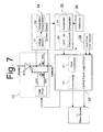
- FIG. 7 is a block and schematic diagram of the solid-state trip circuit according to the invention.
- FIG. 1 there is shown the basic emitter turn-off (ETO) thyristor as used in the practice of certain aspects of the invention.
- ETO emitter turn-off
- the ETO thyristor is described in more detail in copending U.S. patent application Ser. No. 09/486,779, the disclosure of which is incorporated herein by reference.
- the ETO thyristor is a new power semiconductor device developed in the Center for Power Electronics Systems (CPES) at Virginia Tech.
- One intrinsic aspect of the ETO thyristor is the positive temperature coefficient of device on-conduction resistance, which guarantees current sharing between devices.
- Another impressive aspect of the ETO thyristor is the built-in current sensing. The 5 kA interruption capability has been tested and a 4 ⁇ s turn-off time has been achieved. No arc is generated, and it is virtually maintenance-free.
- FIG. 1 shows the ETO thyristor 10 equivalent circuit.
- the gate turn-off (GTO) thyristor 11 is a four-layer semiconductor device of the structure PNPN, usually fabricated on a single wafer up to six inches in diameter. In the on-state it exhibits a latching behavior which enables it to achieve very low conduction loss at a high current density.
- the ETO thyristor has an additional switch 12 in series with the cathode of the GTO thyristor.
- the cathode of the GTO thyristor 11 is the emitter of the internal NPN transistor, so the series switch 12 is referred to as the emitter switch.
- An additional switch 13 is connected to the gate of the GTO thyristor, and is complementary to the emitter switch. These switches are implemented with a number of paralleled low-voltage, high-current metal oxide semiconductor field effect transistors (MOSFETs).
- MOSFETs metal oxide semiconductor field effect transistors
- the ETO thyristor has an Anode 14 , which is the anode of the GTO thyristor 11 , a Cathode 15 , which is the source of MOSFET 12 , and three control electrodes, Gate 1 , which is the gate of the GTO thyristor 11 , Gate 2 , which is the gate of the MOSFET 12 , and Gate 3 , which is the gate of the MOSFET 13 .
- the three control electrodes are controlled by gate driver circuit 16 .
- a high current, high speed solid-state DC circuit breaker is built based on the ETO thyristor technology.
- the ETO-based DC circuit breaker shortens the turn-off time from milliseconds to microseconds, providing fast protection for critical loads. Since both the switch and the tripping unit are solid-state, it is easy to meet the requirements for precise protection. And the solid-state DC circuit breaker has a flexible interface and is easy to control.
- the ETO-based DC circuit breaker shows superior performance to mechanical circuit breakers without increasing cost of manufacture. It can be used in electric traction systems, mining trolley systems, power stations and industrial applications.
- FIG. 2 is a graph showing the built-in current sensing mechanism of the ETO thyristor.
- the emitter switch 12 behaves like a resistor during the turn on-state. Hence, the voltage drop on the emitter switch 12 reflects the current flowing through the device.
- the ETO thyristor has an intrinsic MOSFET to sense the device current.
- the MOSFET voltage drop is proportional to the device current. The voltage falls into the 0 to 0.5 volt range, which can be directly picked by a differential amplifier. Further investigation revealed that the resistance varies with the temperature of the emitter switch 12 . It has a positive temperature coefficient. After temperature compensation, the current can be extracted.
- This built-in current sensing technology can be used for device protection.
- FIG. 3 shows one possible configuration of the ETO-based circuit breaker according to the invention.
- the DC voltage source 21 is connected through the solid-state circuit breaker 20 to a load 23 .
- the solid-state circuit breaker consists of an input clamping capacitor 24 connected across the DC voltage source 21 , which absorbs the up-stream inductor energy during current interruption, an RCD clamp 25 connected across the DC voltage source 21 , which limits the voltage spike on the ETO-based circuit breaker, and a free-wheeling diode 26 connected across the load 23 , which is used to provide an alternative path for the load current. While the ETO thyristor withstands high voltage stress during current interruption, it requires a large clamping capacitor in the clamp 25 at high current rating.
- the clamp 25 can be replaced by other voltage limiting devices, such a Metal Oxide Varistor (MOV).
- MOV Metal Oxide Varistor
- the ETO thyristor 22 connects the positive terminal of the DC voltage source 21 to the positive terminal of the load 23 .
- the load is represented as an inductor because most industrial loads are inductive.
- a solid-state trip circuit 27 controls the ETO thyristor 22 .
- several ETO thyristors may be paralleled to share the current.
- three ETO thyristor devices were tested and found to be good at current sharing during steady state and in switching transition.
- the on-state resistance has intrinsic positive temperature coefficient, which ensures device current sharing.
- FIG. 4 shows another possible configuration of the ETO-based circuit breaker according to the invention.
- the DC voltage source 21 is connected through circuit breaker 20 to a load 23 .
- the solid-state circuit breaker 20 in this configuration consists of an input clamping capacitor 24 connected across the DC voltage source 21 , which absorbs the up-stream inductor energy during current interruption, an RCD snubber 31 connected across the ETO thyristor 22 , which is used to limit the voltage spike on the ETO-based circuit breaker, and a free-wheeling diode 26 , which provides an alternative path for the load current.
- a solid-state trip circuit 27 controls the ETO thyristor 22 .
- ETO thyristors may be paralleled to share the current.
- This configuration adopts the RCD snubber 31 to limit the voltage spike by providing a commutation path for the interrupted current.
- the dv/dt slope can be adjusted by proper choice of the snubber capacitor.
- the RCD snubber 31 can be replaced by other voltage limiting devices, such as a MOV.
- the ETO thyristor withstands low voltage stress during current interruption. This configuration is suitable for high voltage, high current DC circuit breaker applications.
- FIG. 5 shows a third possible configuration of the ETO-based circuit breaker according to the invention.
- the DC voltage source 21 is connected through the solid-state circuit breaker 20 to a load 23 .
- the solid-state circuit breaker 20 consists of an RC snubber 32 connected in parallel with the ETO thyristor 22 , which is used to limit the voltage spike on the ETO-based circuit breaker, and an anti-parallel diode 33 , which is used to provide a reverse current path for the load during regeneration.
- the anti-parallel diode 33 replaces the free-wheeling diode 26 in the first two configurations.
- the dv/dt slope can be adjusted by proper choice of the snubber capacitor.
- a solid-state trip circuit 27 controls the ETO thyristor 22 .
- the ETO thyristor 22 withstands low voltage stress during current interruption. This configuration is suitable for high voltage DC circuit breaker applications.
- a particular advantage of the ETO-based circuit breaker according to the invention is that we use a 2-port network to implement the circuit breaker. This allows easy desegmentation of the faulted DC network from the healthy DC networks without causing high stress at the source side or the load side.
- FIG. 6 Test results for the configuration shown in FIG. 3 are shown in FIG. 6 . These results were obtained in a 5 kA interruption experiment. As seen in the graph, the ETO-based DC circuit breaker safely interrupted 5 kA in 4 ⁇ s. Three ETO thyristors were used in parallel. The critical issue associated with parallel operation is current sharing. From FIG. 6 , we see that current decreases to zero after current regulation between the devices. The turn-off time of 4 ⁇ s can meet the harsh requirements for most critical and sensitive loads.
- FIG. 7 shows the solid-state trip circuit 27 used in the configurations of FIGS. 3 , 4 and 5 .
- a current sensor circuit 34 detects the emitter switch voltage of the ETO thyristor 10 .
- the current sensor includes a voltage sensor 341 and a temperature compensation circuit 342 .
- the current sensor circuit 34 after temperature compensation, calculates the conduction current.
- An over current comparator 35 compares the device current from the current sensor circuit 34 with a precise voltage reference 36 .
- the over current comparator 35 includes a comparator 351 and a latch 352 . If the device current exceeds the predefined reference, the over current comparator 35 will generate a fault signal and latch it.
- a central fault logic circuit 37 receives the fault signal from the over current comparator 35 and fault signals from other devices 38 .
- the central fault logic circuit 37 includes a fault combination circuit 371 and a transmitter 372 . After fault combination, the central fault logic circuit 37 transmits the fault signal to all the ETO devices, shutting down all the ETO
- ETO-based DC circuit breaker utilizes the device built-in current sensor, it does not exclude the use of an external current sensor, for instance a Hall effect current sensor located in the load side to replace the current sensor 34 .
Abstract
Description
Claims (20)
Priority Applications (1)
| Application Number | Priority Date | Filing Date | Title |
|---|---|---|---|
| US10/390,712 US6952335B2 (en) | 2002-03-22 | 2003-03-19 | Solid-state DC circuit breaker |
Applications Claiming Priority (2)
| Application Number | Priority Date | Filing Date | Title |
|---|---|---|---|
| US36625502P | 2002-03-22 | 2002-03-22 | |
| US10/390,712 US6952335B2 (en) | 2002-03-22 | 2003-03-19 | Solid-state DC circuit breaker |
Publications (2)
| Publication Number | Publication Date |
|---|---|
| US20030183838A1 US20030183838A1 (en) | 2003-10-02 |
| US6952335B2 true US6952335B2 (en) | 2005-10-04 |
Family
ID=28457130
Family Applications (1)
| Application Number | Title | Priority Date | Filing Date |
|---|---|---|---|
| US10/390,712 Expired - Fee Related US6952335B2 (en) | 2002-03-22 | 2003-03-19 | Solid-state DC circuit breaker |
Country Status (1)
| Country | Link |
|---|---|
| US (1) | US6952335B2 (en) |
Cited By (24)
| Publication number | Priority date | Publication date | Assignee | Title |
|---|---|---|---|---|
| US20050135034A1 (en) * | 2003-12-19 | 2005-06-23 | Caterpillar, Inc. | Resettable circuit breaker |
| US20060056118A1 (en) * | 2004-09-14 | 2006-03-16 | Kh Controls, Inc. | Limiting energy in wiring faults |
| US20060241876A1 (en) * | 2005-03-08 | 2006-10-26 | Tennessee Valley Authority | Method and apparatus for managing ultracapacitor energy storage systems for a power transmission system |
| US20070086137A1 (en) * | 2005-10-19 | 2007-04-19 | Casey Kelly C | Linear low capacitance overvoltage protection circuit |
| US20070121257A1 (en) * | 2005-11-30 | 2007-05-31 | Arindam Maitra | Multifunction hybrid solid-state switchgear |
| US20080308394A1 (en) * | 2007-06-15 | 2008-12-18 | General Electric Company | Micro-electromechanical system based switching |
| US20090206059A1 (en) * | 2008-02-19 | 2009-08-20 | Kiko Frederick J | Intelligent circuit breaker apparatus and methods |
| US20100001783A1 (en) * | 2006-05-18 | 2010-01-07 | Stmicroelectronics S.R.L. | Three-terminal power device with high switching speed and manufacturing process |
| US7973533B2 (en) | 2008-02-27 | 2011-07-05 | Vertical Power, Inc. | In-circuit testing for integrity of solid-state switches |
| US20130234780A1 (en) * | 2011-01-31 | 2013-09-12 | Richtek Technology Corp. | Adaptive thermal compensation circuit and method |
| US8901897B2 (en) | 2012-03-02 | 2014-12-02 | International Business Machines Corporation | Operating a DC-DC converter |
| US8957514B1 (en) | 2013-10-09 | 2015-02-17 | Lenovo Enterprise Solutions (Singapore) Pte. Ltd. | Operating and manufacturing a DC-DC converter |
| US9054530B2 (en) | 2013-04-25 | 2015-06-09 | General Atomics | Pulsed interrupter and method of operation |
| US9219422B1 (en) | 2014-08-21 | 2015-12-22 | Lenovo Enterprise Solutions (Singapore) Pte. Ltd. | Operating a DC-DC converter including a coupled inductor formed of a magnetic core and a conductive sheet |
| US9225162B2 (en) | 2012-12-20 | 2015-12-29 | General Electric Company | System and method for fault protection |
| US9281748B2 (en) | 2012-03-02 | 2016-03-08 | Lenovo Enterprise Solutions (Singapore) Pte. Ltd. | Operating a DC-DC converter |
| RU2577031C1 (en) * | 2012-02-29 | 2016-03-10 | Абб Текнолоджи Лтд | Direct current power source for power unit |
| US9343897B2 (en) | 2014-07-07 | 2016-05-17 | General Electric Company | Circuit breaker system and method |
| US9379619B2 (en) | 2014-10-21 | 2016-06-28 | Lenovo Enterprise Solutions (Singapore) Pte. Ltd. | Dividing a single phase pulse-width modulation signal into a plurality of phases |
| US9384922B2 (en) | 2011-02-05 | 2016-07-05 | Alevo International, S.A. | Commutating circuit breaker |
| US9618539B2 (en) | 2015-05-28 | 2017-04-11 | Lenovo Enterprise Solutions (Singapore) Pte. Ltd. | Sensing current of a DC-DC converter |
| US10187056B2 (en) | 2013-05-21 | 2019-01-22 | Ge Energy Power Conversion Technology Limited | Device and method to break the current in power transmission or distribution system |
| US11070052B2 (en) | 2016-12-21 | 2021-07-20 | Abb S.P.A. | Circuit protection system |
| US11329589B2 (en) | 2012-03-28 | 2022-05-10 | Joy Global Underground Mining Llc | Ground fault detection methods on variable frequency drive systems |
Families Citing this family (37)
| Publication number | Priority date | Publication date | Assignee | Title |
|---|---|---|---|---|
| US20050073789A1 (en) * | 2003-08-28 | 2005-04-07 | James Tanis | Solid state multi-pole switching device for plug-in switching units |
| DE102005040543A1 (en) * | 2005-08-26 | 2007-03-01 | Siemens Ag | Converter circuit with distributed energy storage |
| US7633725B2 (en) * | 2005-12-20 | 2009-12-15 | General Electric Company | Micro-electromechanical system based soft switching |
| US20070139829A1 (en) * | 2005-12-20 | 2007-06-21 | General Electric Company | Micro-electromechanical system based arc-less switching |
| US7876538B2 (en) * | 2005-12-20 | 2011-01-25 | General Electric Company | Micro-electromechanical system based arc-less switching with circuitry for absorbing electrical energy during a fault condition |
| US7643256B2 (en) | 2006-12-06 | 2010-01-05 | General Electric Company | Electromechanical switching circuitry in parallel with solid state switching circuitry selectively switchable to carry a load appropriate to such circuitry |
| US7542250B2 (en) * | 2007-01-10 | 2009-06-02 | General Electric Company | Micro-electromechanical system based electric motor starter |
| US9076607B2 (en) * | 2007-01-10 | 2015-07-07 | General Electric Company | System with circuitry for suppressing arc formation in micro-electromechanical system based switch |
| US8144445B2 (en) * | 2007-06-12 | 2012-03-27 | General Electric Company | Micro-electromechanical system based switching |
| US7808764B2 (en) * | 2007-10-31 | 2010-10-05 | General Electric Company | System and method for avoiding contact stiction in micro-electromechanical system based switch |
| JP2011010393A (en) | 2009-06-23 | 2011-01-13 | Panasonic Electric Works Co Ltd | Apparatus for protecting direct current branch circuit |
| WO2011141053A1 (en) | 2010-05-11 | 2011-11-17 | Abb Technology Ag | A high voltage dc switchyard with semiconductor switches |
| US8817441B2 (en) * | 2010-08-04 | 2014-08-26 | Cree, Inc. | Circuit breaker |
| GB2484737B (en) * | 2010-10-22 | 2013-11-13 | Ge Aviat Systems Ltd | Power controller system |
| FR2975224B1 (en) * | 2011-05-12 | 2013-07-26 | St Microelectronics Sa | HIGH PERFORMANCE PROTECTION DEVICE AGAINST ELECTROSTATIC DISCHARGES |
| US8638531B2 (en) * | 2011-12-14 | 2014-01-28 | Eaton Corporation | Hybrid bi-directional DC contactor and method of controlling thereof |
| CN102684230A (en) * | 2012-06-14 | 2012-09-19 | 浙江大学 | Compound complete control solid state switch applied to high-voltage high-capacity alternating/direct current power transmission and distribution system |
| WO2014032697A1 (en) * | 2012-08-28 | 2014-03-06 | Abb Technology Ltd | Switching device and system for operating an electric load |
| EP2790285B1 (en) | 2013-04-12 | 2020-07-08 | General Electric Technology GmbH | Current limiter |
| US9136691B2 (en) * | 2013-08-08 | 2015-09-15 | Tyco Electronics Corporation | Solid state relay protective device |
| US10389104B1 (en) * | 2015-01-09 | 2019-08-20 | Clemson University | Circuit breaker for DC circuits using coupled induction |
| US9998116B2 (en) | 2015-08-03 | 2018-06-12 | Rockwell Automation Technologies, Inc. | Auxiliary commutated silicon-controlled rectifier circuit methods and systems |
| CN105070558A (en) * | 2015-09-21 | 2015-11-18 | 上海电机学院 | High-voltage direct-current circuit breaker |
| US10103729B2 (en) * | 2016-09-28 | 2018-10-16 | Rockwell Automation Technologies, Inc. | Auxiliary commutated silicon-controlled rectifier circuit methods and systems |
| KR101923135B1 (en) | 2016-12-26 | 2018-11-28 | 효성중공업 주식회사 | Modular multilevel converter system |
| WO2020045889A1 (en) * | 2018-08-27 | 2020-03-05 | 엘에스산전 주식회사 | Bidirectional semiconductor circuit breaker |
| KR102652596B1 (en) * | 2018-08-27 | 2024-04-01 | 엘에스일렉트릭(주) | Bi-directional solid state circuit breaker |
| EP3654477A1 (en) * | 2018-11-15 | 2020-05-20 | Siemens Aktiengesellschaft | Electronic switch with surge protector |
| CN110970882A (en) * | 2018-12-24 | 2020-04-07 | 宁德时代新能源科技股份有限公司 | Protection circuit and battery management system |
| CN113994030A (en) * | 2019-04-24 | 2022-01-28 | 联邦科学和工业研究组织 | Short circuit relieving device |
| CN110518544B (en) * | 2019-08-22 | 2020-08-07 | 西南交通大学 | Solid-state direct current breaker based on normal-open SIC device series structure |
| CN110429562B (en) * | 2019-08-22 | 2020-11-06 | 西南交通大学 | Hybrid high-voltage direct-current circuit breaker based on normally-on SIC device and control method thereof |
| SE544134C2 (en) * | 2019-09-05 | 2022-01-11 | Scania Cv Ab | An electronic circuit breaker with self-triggering protection for a vehicle, and a method therefor |
| SE545661C2 (en) * | 2019-09-05 | 2023-11-28 | Scania Cv Ab | A battery junction box and a battery pack for a vehicle |
| CN111446950B (en) * | 2020-04-15 | 2023-04-07 | 国网安徽省电力有限公司电力科学研究院 | Direct current solid-state circuit breaking device |
| CN112152599A (en) * | 2020-08-13 | 2020-12-29 | 中车株洲电力机车研究所有限公司 | All-solid-state direct current circuit breaker |
| CN116192106A (en) * | 2023-03-14 | 2023-05-30 | 珠海汇众能源科技有限公司 | Direct current breaker circuit |
Citations (5)
| Publication number | Priority date | Publication date | Assignee | Title |
|---|---|---|---|---|
| US4581543A (en) * | 1982-08-18 | 1986-04-08 | Siemens Aktiengesellschaft | Semiconductor switch having a disconnectible thyristor |
| US5262691A (en) * | 1990-09-18 | 1993-11-16 | General Electric Company | Gate turnoff thyristor control circuit with shorted gate detection |
| US6163200A (en) * | 1998-06-11 | 2000-12-19 | Elmec Inc. | Gate driver device for GTO thyristor |
| US6426666B1 (en) * | 1999-11-10 | 2002-07-30 | Virginia Tech Intellectual Properties, Inc. | Diode-assisted gate turn-off thyristor |
| US6710639B2 (en) * | 2002-03-06 | 2004-03-23 | Virginia Tech Intellectual Properties, Inc. | Emitter turn-off thyristors and their drive circuits |
-
2003
- 2003-03-19 US US10/390,712 patent/US6952335B2/en not_active Expired - Fee Related
Patent Citations (5)
| Publication number | Priority date | Publication date | Assignee | Title |
|---|---|---|---|---|
| US4581543A (en) * | 1982-08-18 | 1986-04-08 | Siemens Aktiengesellschaft | Semiconductor switch having a disconnectible thyristor |
| US5262691A (en) * | 1990-09-18 | 1993-11-16 | General Electric Company | Gate turnoff thyristor control circuit with shorted gate detection |
| US6163200A (en) * | 1998-06-11 | 2000-12-19 | Elmec Inc. | Gate driver device for GTO thyristor |
| US6426666B1 (en) * | 1999-11-10 | 2002-07-30 | Virginia Tech Intellectual Properties, Inc. | Diode-assisted gate turn-off thyristor |
| US6710639B2 (en) * | 2002-03-06 | 2004-03-23 | Virginia Tech Intellectual Properties, Inc. | Emitter turn-off thyristors and their drive circuits |
Non-Patent Citations (1)
| Title |
|---|
| Xu et al., The Emiter turn-Off thyristor-Based DC Circuit Breaker Jan. 27, 2002 IEEE pp. 288-293 vol. 1. * |
Cited By (38)
| Publication number | Priority date | Publication date | Assignee | Title |
|---|---|---|---|---|
| US20050135034A1 (en) * | 2003-12-19 | 2005-06-23 | Caterpillar, Inc. | Resettable circuit breaker |
| US20060056118A1 (en) * | 2004-09-14 | 2006-03-16 | Kh Controls, Inc. | Limiting energy in wiring faults |
| US20060241876A1 (en) * | 2005-03-08 | 2006-10-26 | Tennessee Valley Authority | Method and apparatus for managing ultracapacitor energy storage systems for a power transmission system |
| US7633284B2 (en) | 2005-03-08 | 2009-12-15 | Tennessee Valley Authority | Method and apparatus for managing ultracapacitor energy storage systems for a power transmission system |
| WO2007047806A2 (en) * | 2005-10-19 | 2007-04-26 | Littelfuse, Inc. | Linear low capacitance overvoltage protection circuit |
| WO2007047806A3 (en) * | 2005-10-19 | 2007-07-12 | Littelfuse Inc | Linear low capacitance overvoltage protection circuit |
| US7515391B2 (en) | 2005-10-19 | 2009-04-07 | Littlefuse, Inc. | Linear low capacitance overvoltage protection circuit |
| US20070086137A1 (en) * | 2005-10-19 | 2007-04-19 | Casey Kelly C | Linear low capacitance overvoltage protection circuit |
| US20070121257A1 (en) * | 2005-11-30 | 2007-05-31 | Arindam Maitra | Multifunction hybrid solid-state switchgear |
| WO2007064837A2 (en) * | 2005-11-30 | 2007-06-07 | Electric Power Research Institute, Inc. | A multifunction hybrid solid-state switchgear |
| WO2007064837A3 (en) * | 2005-11-30 | 2008-01-10 | Electric Power Res Inst | A multifunction hybrid solid-state switchgear |
| US7405910B2 (en) * | 2005-11-30 | 2008-07-29 | Electric Power Research Institute, Inc. | Multifunction hybrid solid-state switchgear |
| US8420454B2 (en) | 2006-05-18 | 2013-04-16 | Stmicroelectronics S.R.L. | Three-terminal power device with high switching speed and manufacturing process |
| US7982528B2 (en) * | 2006-05-18 | 2011-07-19 | Stmicroelectronics, S.R.L. | Three-terminal power device with high switching speed and manufacturing process |
| US20100001783A1 (en) * | 2006-05-18 | 2010-01-07 | Stmicroelectronics S.R.L. | Three-terminal power device with high switching speed and manufacturing process |
| US20110129967A1 (en) * | 2006-05-18 | 2011-06-02 | Stmicroelectronics S.R.I. | Three-terminal power device with high switching speed and manufacturing process |
| US8358488B2 (en) * | 2007-06-15 | 2013-01-22 | General Electric Company | Micro-electromechanical system based switching |
| US20080308394A1 (en) * | 2007-06-15 | 2008-12-18 | General Electric Company | Micro-electromechanical system based switching |
| US20090206059A1 (en) * | 2008-02-19 | 2009-08-20 | Kiko Frederick J | Intelligent circuit breaker apparatus and methods |
| US8773827B2 (en) | 2008-02-19 | 2014-07-08 | Simply Automated Incorporated | Intelligent circuit breaker apparatus and methods |
| US7973533B2 (en) | 2008-02-27 | 2011-07-05 | Vertical Power, Inc. | In-circuit testing for integrity of solid-state switches |
| US20130234780A1 (en) * | 2011-01-31 | 2013-09-12 | Richtek Technology Corp. | Adaptive thermal compensation circuit and method |
| US8698548B2 (en) * | 2011-01-31 | 2014-04-15 | Richtek Technology Corp. | Adaptive thermal compensation circuit and method |
| US9384922B2 (en) | 2011-02-05 | 2016-07-05 | Alevo International, S.A. | Commutating circuit breaker |
| RU2577031C1 (en) * | 2012-02-29 | 2016-03-10 | Абб Текнолоджи Лтд | Direct current power source for power unit |
| US9281748B2 (en) | 2012-03-02 | 2016-03-08 | Lenovo Enterprise Solutions (Singapore) Pte. Ltd. | Operating a DC-DC converter |
| US8901897B2 (en) | 2012-03-02 | 2014-12-02 | International Business Machines Corporation | Operating a DC-DC converter |
| US11329589B2 (en) | 2012-03-28 | 2022-05-10 | Joy Global Underground Mining Llc | Ground fault detection methods on variable frequency drive systems |
| US9225162B2 (en) | 2012-12-20 | 2015-12-29 | General Electric Company | System and method for fault protection |
| US9054530B2 (en) | 2013-04-25 | 2015-06-09 | General Atomics | Pulsed interrupter and method of operation |
| US10187056B2 (en) | 2013-05-21 | 2019-01-22 | Ge Energy Power Conversion Technology Limited | Device and method to break the current in power transmission or distribution system |
| US9236347B2 (en) | 2013-10-09 | 2016-01-12 | Lenovo Enterprise Solutions (Singapore) Pte. Ltd. | Operating and manufacturing a DC-DC converter |
| US8957514B1 (en) | 2013-10-09 | 2015-02-17 | Lenovo Enterprise Solutions (Singapore) Pte. Ltd. | Operating and manufacturing a DC-DC converter |
| US9343897B2 (en) | 2014-07-07 | 2016-05-17 | General Electric Company | Circuit breaker system and method |
| US9219422B1 (en) | 2014-08-21 | 2015-12-22 | Lenovo Enterprise Solutions (Singapore) Pte. Ltd. | Operating a DC-DC converter including a coupled inductor formed of a magnetic core and a conductive sheet |
| US9379619B2 (en) | 2014-10-21 | 2016-06-28 | Lenovo Enterprise Solutions (Singapore) Pte. Ltd. | Dividing a single phase pulse-width modulation signal into a plurality of phases |
| US9618539B2 (en) | 2015-05-28 | 2017-04-11 | Lenovo Enterprise Solutions (Singapore) Pte. Ltd. | Sensing current of a DC-DC converter |
| US11070052B2 (en) | 2016-12-21 | 2021-07-20 | Abb S.P.A. | Circuit protection system |
Also Published As
| Publication number | Publication date |
|---|---|
| US20030183838A1 (en) | 2003-10-02 |
Similar Documents
| Publication | Publication Date | Title |
|---|---|---|
| US6952335B2 (en) | Solid-state DC circuit breaker | |
| US9755630B2 (en) | Solid-state circuit breakers and related circuits | |
| US6075684A (en) | Method and arrangement for direct current circuit interruption | |
| CN107070191B (en) | Device for temporarily taking over the current of an energy transmission or distribution system as required | |
| US9972997B2 (en) | Circuit interruption device | |
| EP2819142B1 (en) | Solid state circuit-breaker switch devices | |
| US11295919B2 (en) | Circuit-breaker with reduced breakdown voltage requirement | |
| US20150131189A1 (en) | Composite high voltage dc circuit breaker | |
| JP7115127B2 (en) | switch device | |
| Peng et al. | Development of medium voltage solid-state fault isolation devices for ultra-fast protection of distribution systems | |
| Peng et al. | Current commutation in a medium voltage hybrid DC circuit breaker using 15 kV vacuum switch and SiC devices | |
| WO2014177874A2 (en) | Apparatus and method for controlling a dc current | |
| KR20160100398A (en) | Device for switching a direct current | |
| Huang et al. | Design and development of a 7.2 kV/200A hybrid circuit breaker based on 15 kV SiC emitter turn-off (ETO) thyristor | |
| US5150287A (en) | Quarter-bridge circuit for high currents | |
| Askan et al. | Bidirectional switch based on silicon high voltage superjunction MOSFETs and TVS diode used in low voltage DC SSCB | |
| CN112997373A (en) | Electric switch with overvoltage protection | |
| Askan et al. | Variable voltage IGBT gate driver for low voltage hybrid circuit breaker | |
| KR20220163337A (en) | Solid State Switch | |
| JP4394301B2 (en) | Current limiting device | |
| Takimoto et al. | Experiment of semiconductor breaker using series-connected IEGTs for hybrid DCCB | |
| CN114128067A (en) | DC distribution board | |
| WO2024002248A1 (en) | Solid-state motor starter | |
| WO2023198313A1 (en) | Bidirectional power semiconductor switch | |
| JP2022117623A (en) | Power conversion device |
Legal Events
| Date | Code | Title | Description |
|---|---|---|---|
| AS | Assignment |
Owner name: VIRGINIA POLYTECHNIC INSTITUTE & STATE UNIVERSITY, Free format text: ASSIGNMENT OF ASSIGNORS INTEREST;ASSIGNORS:HUANG, QIN;ZHOU, XIGEN;XU, XHENXUE;REEL/FRAME:015887/0740 Effective date: 20030318 Owner name: VIRGINIA TECH INTELLECTUAL PROPERTIES, INC., VIRGI Free format text: ASSIGNMENT OF ASSIGNORS INTEREST;ASSIGNOR:VIRGINIA POLYTECHNIC INSTITUTE & STATE UNIVERSITY;REEL/FRAME:015887/0761 Effective date: 20041005 |
|
| AS | Assignment |
Owner name: VIRGINIA POLYTECHNIC INSTITUTE & STATE UNIVERSITY, Free format text: CORRECTIVE ASSIGNMENT TO CORRECT THE 3RD ASSIGNOR'S 1ST NAME, PREVIOUSLY RECORDED AT REEL 015887 FRAME 0740;ASSIGNORS:HUANG, QIN;ZHOU, XIGEN;XU, ZHENXUE;REEL/FRAME:016482/0262 Effective date: 20030318 |
|
| FPAY | Fee payment |
Year of fee payment: 4 |
|
| FEPP | Fee payment procedure |
Free format text: PAYOR NUMBER ASSIGNED (ORIGINAL EVENT CODE: ASPN); ENTITY STATUS OF PATENT OWNER: SMALL ENTITY |
|
| FPAY | Fee payment |
Year of fee payment: 8 |
|
| REMI | Maintenance fee reminder mailed | ||
| LAPS | Lapse for failure to pay maintenance fees |
Free format text: PATENT EXPIRED FOR FAILURE TO PAY MAINTENANCE FEES (ORIGINAL EVENT CODE: EXP.) |
|
| STCH | Information on status: patent discontinuation |
Free format text: PATENT EXPIRED DUE TO NONPAYMENT OF MAINTENANCE FEES UNDER 37 CFR 1.362 |
|
| FP | Lapsed due to failure to pay maintenance fee |
Effective date: 20171004 |