US6952197B1 - Pointing device - Google Patents
Pointing device Download PDFInfo
- Publication number
- US6952197B1 US6952197B1 US09/559,261 US55926100A US6952197B1 US 6952197 B1 US6952197 B1 US 6952197B1 US 55926100 A US55926100 A US 55926100A US 6952197 B1 US6952197 B1 US 6952197B1
- Authority
- US
- United States
- Prior art keywords
- operating part
- base part
- section
- magnet
- pointing device
- Prior art date
- Legal status (The legal status is an assumption and is not a legal conclusion. Google has not performed a legal analysis and makes no representation as to the accuracy of the status listed.)
- Expired - Fee Related
Links
Images


Classifications
-
- G—PHYSICS
- G06—COMPUTING; CALCULATING OR COUNTING
- G06F—ELECTRIC DIGITAL DATA PROCESSING
- G06F3/00—Input arrangements for transferring data to be processed into a form capable of being handled by the computer; Output arrangements for transferring data from processing unit to output unit, e.g. interface arrangements
- G06F3/01—Input arrangements or combined input and output arrangements for interaction between user and computer
- G06F3/03—Arrangements for converting the position or the displacement of a member into a coded form
- G06F3/033—Pointing devices displaced or positioned by the user, e.g. mice, trackballs, pens or joysticks; Accessories therefor
- G06F3/0338—Pointing devices displaced or positioned by the user, e.g. mice, trackballs, pens or joysticks; Accessories therefor with detection of limited linear or angular displacement of an operating part of the device from a neutral position, e.g. isotonic or isometric joysticks
-
- G—PHYSICS
- G05—CONTROLLING; REGULATING
- G05G—CONTROL DEVICES OR SYSTEMS INSOFAR AS CHARACTERISED BY MECHANICAL FEATURES ONLY
- G05G9/00—Manually-actuated control mechanisms provided with one single controlling member co-operating with two or more controlled members, e.g. selectively, simultaneously
- G05G9/02—Manually-actuated control mechanisms provided with one single controlling member co-operating with two or more controlled members, e.g. selectively, simultaneously the controlling member being movable in different independent ways, movement in each individual way actuating one controlled member only
- G05G9/04—Manually-actuated control mechanisms provided with one single controlling member co-operating with two or more controlled members, e.g. selectively, simultaneously the controlling member being movable in different independent ways, movement in each individual way actuating one controlled member only in which movement in two or more ways can occur simultaneously
- G05G9/047—Manually-actuated control mechanisms provided with one single controlling member co-operating with two or more controlled members, e.g. selectively, simultaneously the controlling member being movable in different independent ways, movement in each individual way actuating one controlled member only in which movement in two or more ways can occur simultaneously the controlling member being movable by hand about orthogonal axes, e.g. joysticks
- G05G2009/0474—Manually-actuated control mechanisms provided with one single controlling member co-operating with two or more controlled members, e.g. selectively, simultaneously the controlling member being movable in different independent ways, movement in each individual way actuating one controlled member only in which movement in two or more ways can occur simultaneously the controlling member being movable by hand about orthogonal axes, e.g. joysticks characterised by means converting mechanical movement into electric signals
- G05G2009/04755—Magnetic sensor, e.g. hall generator, pick-up coil
Definitions
- the present invention relates to a pointing device which can be suitably provided in a data processor such as a personal computer.
- a pointing device is conventionally used as an auxiliary input device for indicating coordinate data on the display by entering analog information through a manual operation by an operator.
- a typical small-sized portable data processor is provided with a built-in type pointing device integrally incorporated in a housing body of the data processor, or otherwise a separate pointing device, such as a mouse, is detachably connected with the processor housing body through a cable and a connector when it is used.
- the conventional pointing device described, e.g., in Japanese Unexamined Patent Publication (Kokai) No. 10-49292 (JP-A-10-49292), includes a base part, an operating part supported on the base part and rockable about a fulcrum provided on the base part, a magnet carried on one of the base part and the operating part, a magneto-electro transducer (generally, a Hall element) carried on the other of the base part and the operating part opposite to the magnet, and an elastic member for pushing or biasing the operating part toward an initial balanced position on the base part.
- a magneto-electro transducer generally, a Hall element
- an operator manually operates the operating part to rock it on the base part against the biasing force of the elastic member, and changes the positional relationship between the magnet and the magneto-electro transducer to vary the output voltage of the magneto-electro transducer, whereby it is possible to enter analog information corresponding to the rocking direction and rocking angle of the operating part.
- the pointing device is mounted with the operating part thereof being exposed on the upper side portion of the housing body adjacent to the keyboard of the data processor.
- the height of the operating part projecting from the upper side of the housing body is reduced as much as possible, in order to ensure the portability of the data processor.
- the pointing device is also required in itself to be reduced in the height thereof, i.e., a distance between the bottom surface of the base part and the top surface of the operating part should be decreased as much as possible.
- the built-in type pointing device as described above essentially imposes an input operation within a limited area on a operator, and besides, there is a possibility of further deteriorating the operational properties when the height reduction is facilitated. Therefore, in the case where the operator regards the good operational properties of the pointing device as important when using the data processor with a reduced thickness, a detachable type pointing device, in which the dimensions are not related to the dimensions of the data processor, is used. In particular, when the data processor is used in a portable way, it is difficult to ensure a space for operating a mouse having a normal structure, in which an operative ball is partially exposed on the back side of the mouse.
- a pointing device having a structure similar to that of the conventional built-in type pointing device is used while being detachably attached to the housing body of the data processor (see, e.g., Japanese Unexamined Patent Publication (Kokai) No. 6-139013 (JP-A-6-139013)).
- the dimension in a vertical direction of the elastic member generally formed by a rubber or a coil spring for biasing the operating part toward the initial position, is excessively reduced, it is possible that a spring force generated when the elastic member is elastically deformed becomes insufficient, which may result in a difficulty in the proper and stable operation of the operating part.
- the conventional detachable pointing device includes a housing accommodating both an operating part and a detecting section for detecting the movement of the operating part.
- a cable extending from the housing is connected through a connector to the data processor, and the housing is mounted at a desired position on the housing body of the data processor.
- Another object of the present invention is to provide a pointing device having a magneto-electro transducer, in which the magnetic leakage through an operating part is decreased even when the height of the pointing device is reduced.
- a further object of the present invention is to provide a pointing device capable of being detachably mounted on a data processor, which can easily perform an electrical connection and mechanical attachment to the data processor and can ensure good portability and a good operational environmental condition of the data processor.
- the present invention provides a pointing device comprising a base part; an operating part supported on the base part in a rockable manner about a fulcrum; a magnet carried on one of the base part and the operating part; a magneto-electro transducer carried on the other of the base part and the operating part; and an elastic member arranged between the base part and the operating part to elastically push the operating part toward an initial balanced position on the base part, the elastic member being formed as a plate spring provided with a first section engageable with the base part and a second section engageable with the operating part, the second section being integrally joined to the first section and located to extend around the fulcrum.
- the first section of the plate spring extends annularly around the fulcrum and is fixedly supported on the base part, and that the second section extends arcuately along the first section to exert a spring action.
- the second section of the plate spring includes a distal free end engageable with the operating part and a proximal end integrally joined to the first section at a position remote from the distal free end, and has a length between the distal end and the proximal end for exerting a spring action.
- the second section of the plate spring includes a distal free end engageable with the operating part and a proximal end integrally joined to the first section at a position close to the distal free end, and has a generally U-shaped length between the distal end and the proximal end for exerting a spring action.
- the pointing device further comprises a yoke forming a magnetic path, the yoke being arranged in the operating part to at least partially cover the magnet.
- the magnet may be carried on the operating part, and the yoke may be arranged adjacent to the magnet on a side remote from the magneto-electro transducer carried on the base part.
- the present invention also provides a pointing device comprising a base part; an operating part supported on the base part in a rockable manner about a fulcrum; a magnet carried on one of the base part and the operating part; a magneto-electro transducer carried on the other of the base part and the operating part; an elastic member arranged between the base part and the operating part to elastically push the operating part toward an initial balanced position on the base part; and a yoke forming a magnetic path, the yoke being arranged in the operating part to at least partially cover the magnet.
- the present invention further provides a pointing device comprising a base part; an operating part supported on the base part in a rockable manner about a fulcrum; a magnet carried on one of the base part and the operating part; a magneto-electro transducer carried on the other of the base part and the operating part; an elastic member arranged between the base part and the operating part to elastically push the operating part toward an initial balanced position on the base part; and a connector part arranged adjacent to the base part and the operating part, the connector part being detachably connectable to a data processor and serving to support the base part and the operating part when the connector part is connected to the data processor.
- the present invention yet further provides a pointing device comprising an operating part; a detecting part for detecting a movement of the operating part; a connector part arranged adjacent to the operating part and the detecting part, the connector part being detachably connectable to a data processor and serving to support the operating part and the detecting part when the connector part is connected to the data processor.
- this pointing device further comprises a housing for accommodating the operating part and the detecting part, the connecting part being rotatably coupled to the housing.
- the housing may include an engaging section engageable with a housing body of the data processor.
- FIG. 1 is an exploded perspective view showing one embodiment of a pointing device according to the present invention
- FIG. 2 is an exploded vertical sectional view showing the pointing device of FIG. 1 ;
- FIG. 3 is a vertical sectional view showing the pointing device of FIG. 1 in an assembled state
- FIG. 4A is a plan view of the pointing device of FIG. 1 ;
- FIG. 4B is a front view of the pointing device of FIG. 1 ;
- FIG. 5A is a vertical sectional view showing the pointing device of FIG. 1 in one operationally tilted position
- FIG. 5B is a vertical sectional view showing the pointing device of FIG. 1 in another operationally tilted position
- FIG. 6 is a perspective view of a modification of a plate spring
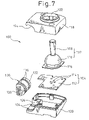
- FIG. 7 is an exploded perspective view showing another embodiment of a pointing device according to the present invention.
- FIG. 8 is a perspective view showing the pointing device of FIG. 7 in an assembled state
- FIG. 9A is a side view of the pointing device of FIG. 7 , as seen from an arrow A of FIG. 8 ;
- FIG. 9B is a side view of the pointing device of FIG. 7 , as seen from an arrow B of FIG. 8 ;
- FIG. 10A is a top plan view of the pointing device of FIG. 7 ;
- FIG. 10B is a bottom plan view of the pointing device of FIG. 7 ;
- FIG. 11A is a perspective view of the pointing device of FIG. 7 ;
- FIG. 11B is a perspective view of a data processor in a condition before the pointing device of FIG. 7 is attached thereto;
- FIG. 12 is a perspective view of the data processor of FIG. 11B to which the pointing device is attached.
- FIGS. 1 to 4 show a pointing device 10 according to one embodiment of the present invention.
- the pointing device 10 can be suitably and advantageously used as an auxiliary input device having a reduced height for indicating coordinate data on a display incorporated in a data processor, particularly in a portable small-sized data processor, such as a personal computer, a personal word processor, and so on.
- the pointing device 10 includes a base part 12 and an operating part 16 supported on the base part 12 and rockable about a fulcrum 14 provided on the base part 12 .
- the base part 12 includes a circuit board 18 onto which electronical elements, such as a CPU (not shown), are mounted, and first and second frame members 20 , 22 fixedly attached in a mutually assembled state to the circuit board 18 .
- a plurality (four, in the illustrated embodiment) of magneto-electro transducers (i.e., Hall elements) 24 are mounted onto the surface of the circuit board 18 at predetermined positions. The magneto-electro transducers 24 are positioned inside the assembled frame members 20 , 22 .
- the first frame member 20 has a thin-plate shape, and includes a generally annular outer circumferential portion 26 and a central portion 28 extending inside the outer circumferential portion 26 to be integrally joined to the latter.
- the central portion 28 is provided with a hemispheric depression which constitutes the fulcrum 14 .
- the second frame member 22 includes a generally cylindrical circumferential wall portion 30 and a plurality (three, in the illustrated embodiment) of flange portions 32 extending locally and radially inside the circumferential wall portion 30 to be integrally joined to the latter.
- the circumferential wall portion 30 and the flange portions 32 define a recess for accommodating the first frame member 20 .
- the outer circumferential portion 26 of the first frame member 20 is provided at predetermined positions on the outer side of the circumferential portion 26 with detents 34 facing outward.
- the circumferential wall portion 30 of the second frame member 22 is provided at predetermined positions on the inner side of the wall portion 30 with detents 36 facing inward and capable of engaging with the detents 34 .
- the first and second frame members 20 , 22 are fixedly assembled together when the detents 34 , 36 thereof are engaged with each other with a snap action, i.e., under the elastic deformation of one or both of the detents 34 , 36 or of the frame members 20 , 22 .
- the first frame member 20 is also provided on the back side of the central portion 28 opposite to the depression for the fulcrum 14 with one projection 38 , and on the corresponding side of the outer circumferential portion 26 with one projection 40 .
- the projections 38 , 40 are fitted respectively into locating holes 42 , 44 provided on the surface of the circuit board 18 , so that the mutually assembled first and second frame members 20 , 22 are located at a predetermined position on the circuit board 18 .
- the magneto-electro transducers 24 mounted on the circuit board 18 are located in respective openings defined between the outer circumferential portion 26 and the central portion 28 of the first frame member 20 and are arranged in a distributed manner in a circumferential direction about the fulcrum 14 .
- the second frame member 22 is secured to the circuit board 18 by a bolt (not shown).
- the operating part 16 includes a cover 46 which an operator touches, and a holder 48 securely assembled to the cover 46 .
- the cover 46 includes a generally disk-shaped end wall portion 50 and a generally cylindrical circumferential wall portion 52 extending axially from an outer edge of the end wall portion 50 to be integrally joined to the latter.
- the end wall portion 50 and the circumferential wall portion 52 define a recess for accommodating the second frame member 22 of the base part 12 .
- the end wall portion 50 of the cover 46 is provided on the outer side of the end wall portion 50 with an operating surface 54 concavely and smoothly curved in an ergonomic manner.
- the end wall portion 50 of the cover 46 is also provided on the inner side thereof with a plurality (three, in the illustrated embodiment) of engaging pieces 58 projecting from the inner side and respectively having detents 56 facing inward.
- the engaging pieces 58 are spaced from the circumferential wall portion 52 and arranged concentrically with the latter.
- the holder 48 includes a generally disk-shaped bottom wall portion 60 and a plurality (three, in the illustrated embodiment) of flange portions 62 extending locally and radially outward from the outer edge of the bottom wall portion 60 to be integrally joined to the latter.
- the bottom wall portion 60 of the holder 48 is provided with a cylindrical wall 64 projecting from the upper side of the bottom wall portion 60 .
- a magnet 66 generally having a disk shape is received in a recess 65 defined by the bottom wall portion 60 and the cylindrical wall 64 .
- the flange portions 62 of the holder 48 are disposed at generally regular intervals in the circumferential direction of the bottom wall portion 60 .
- Supplemental walls 68 extending generally parallel to the cylindrical wall 64 are respectively formed between the bottom wall portion 60 and the flange portions 62 .
- the bottom wall portion 60 is also provided with detents 70 facing outward, respectively, on the outer peripheral regions of the wall portion 60 , in which no flange portion 62 is formed.
- the cover 46 and the holder 48 are fixedly assembled together when the detents 56 on the engaging pieces 58 of the cover 46 are respectively engaged with the detents 70 of the holder 48 with a snap action. In this state, each of the supplemental walls 68 of the holder 48 is located between two engaging pieces 58 of the cover 46 arranged side-by-side in a circumferential direction.
- the bottom wall portion 60 of the holder 48 is provided with a generally conical back side opposite to the upper side having the cylindrical wall 64 , the conical back side convexly extending from the outer periphery to the center of the bottom wall portion 60 , so as to form a generally hemispherical bulge 72 at the vertex of the conical back side.
- the second frame member 22 is received into the recess defined between the end and circumferential wall portions 50 , 52 of the cover 46 secured to the holder 48 , and the bulge 72 of the holder 48 is slidably received and closely fitted into the depression for the fulcrum 14 provided on the central portion 28 of the first frame member 20 .
- the holder 48 is supported together or integrally with the cover 46 and the magnet 66 on the first frame member 20 and is rockable, in every direction, about the fulcrum 14 .
- the magnet 66 is located facing the magneto-electro transducers 24 provided on the circuit board 18 and is spaced from the transducers 24 at a predetermined distance.
- the pointing device 10 also includes a plate spring 74 acting as an elastic member for biasing or urging the operating part 16 toward an initial balanced position on the base part 12 .
- the plate spring 74 includes a first section 76 capable of being engaged with the base part 12 , and a plurality (three, in the illustrated embodiment) of second sections 78 integrally extending from the first section 76 and capable of being engaged with the operating part 16 .
- the plate spring 74 has a plate-like shape and may be made, e.g., through a blanking process from a spring steel.
- the first section 76 of the plate spring 74 extends around the fulcrum 14 in a generally circular and annular shape, and is fixedly supported between the first and second frame members 20 , 22 of the base part 12 .
- the second sections 78 of the plate spring 74 arcuately extend along and inside the first section 76 from the plural points of the first section 76 defined at regular intervals in the circumferential direction, and are respectively supported at the free ends thereof on the flange portions 62 of the holder 48 of the operating part 16 .
- the first and second sections 76 , 78 of the plate spring 74 are maintained generally flush with each other during an unloaded state, as shown in FIGS. 1 and 2 .
- each second section 78 is elastically deformed so as to exert a spring action against the external force.
- the plate spring 74 is also provided with through holes 80 , each of which is formed near the proximal end of each second section 78 , i.e., in a connecting area between each second section 78 and the first section 76 .
- the second frame member 22 of the base part 12 is also provided with locating protrusions 82 disposed correspondingly to the through holes 80 , each protrusion 82 being formed on the inner side of each flange portion 32 .
- the first section 76 of the plate spring 74 is held between the outer circumferential portion 26 of the first frame member 20 and the flange portions 32 of the second frame member 22 , with the protrusions 82 of the second frame member 22 being respectively inserted into the through holes 80 of the first frame member 20 , and thereby the plate spring 74 is incorporated within the base part 12 .
- each second section 78 of the plate spring 74 is engaged at the free end thereof with the upper surface, facing away from the circuit board 18 , of each flange portion 62 of the holder 48 .
- the respective components are sized and configured so that all of the second sections 78 are evenly loaded by the corresponding flange portions 62 to be elastically deformed and bent slightly upward (see FIG. 3 ).
- the second sections 78 of the plate spring 74 exert a generally even spring force onto the respective flange portions 62 of the holder 48 in a downward direction toward the circuit board 18 .
- the operating part 16 formed from the cover 46 and the holder 48 is stably and elastically held in an initial balanced position together or integrally with the magnet 66 .
- the end wall portion 50 of the cover 46 is disposed generally parallel to the circuit board 18 , and the magneto-electro transducers 24 on the circuit board 18 are positioned at generally equal distance from the magnet 66 on the operating part 16 .
- the fluctuation of the output voltage of each magneto-electro transducer 24 due to the rocking motion of the cover 46 is processed as an analogue information in the CPU (not shown) to be converted into digital coordinate data, which in turn is output through a connector 84 ( FIG. 1 ) provided on the circuit board 18 to a processing mechanism in a data processor (not shown).
- a character or cursor on a display of the data processor in a desired direction and over a desired distance, corresponding to the rocking direction and angle of the cover 46 of the operating part 16 .
- the second sections 78 of the plate spring 74 change the elastic deformations thereof from a balanced mode into an unbalanced mode corresponding to the rocking direction of the cover 46 , due to the rocking motion of the flange portions 62 of the holder 48 . Therefore, the operating part 16 is continuously biased or pushed toward the initial balanced position by the spring force, due to the elastically deformed second sections 78 of the plate spring 74 , which tends to recover the balanced mode thereof. Consequently, the operating part 16 can smoothly rock while properly corresponding to an operator's finger action, and can readily return to the initial position at substantially the same time as the operator releases the cover 46 from his finger.
- the pointing device 10 incorporates therein a plate spring 74 having a thin-plate shape as an elastic member for biasing the operating part 16 toward the initial position, so that the height or vertical dimension of the pointing device 10 in an assembled state can be easily reduced.
- the plate spring 74 includes the second sections 78 extending in an arcuate shape around the fulcrum 14 along the first section 76 , whereby a spring force necessary and sufficient for a stable manipulation of the operating part 16 can be exerted from each second section 78 extending into a desired length in a circumferential direction, in spite of the significantly small height of the plate spring 74 .
- the pointing device 10 can reduce the entire height or vertical dimension thereof in the assembled state without deteriorating the operational properties of the operating part 16 , and thus can facilitate the reduction of thickness of a data processor in the case where the pointing device 10 is integrally incorporated, for use, in the housing body of the data processor.
- the plate spring 74 of the pointing device 10 may have various shapes and dimensions other than the above described configuration.
- the adaptable plate spring 74 may include second sections 78 ′, each of which extends in a generally U-shape from the proximal end thereof joined to the first section 76 .
- each second section 78 ′ is engaged at the distal free end 79 thereof with the flange portion 62 of the holder 48 .
- This modification makes it possible to easily increase the whole length of the second section 78 ′ for exerting a spring action, and thus to obtain a larger spring force.
- the plate spring 74 described in connection with the above embodiment may also be effectively used in another pointing device in which a magnet and magneto-electro transducers are arranged opposite to the above embodiment, that is, in which magneto-electro transducers provided in a operating part are moved relative to a magnet provided in a base part, within the scope of the present invention.
- the above-described effects are also obtainable.
- the pointing device 10 further includes a yoke 86 placed in the operating part 16 above the magnet 66 to constitute a magnetic path.
- the yoke 86 has a dish-like configuration which may be made through a drawing process from a metal plate such as a magnetic steel plate, and includes a generally circular end wall portion 88 and a generally cylindrical circumferential wall portion 90 extending axially from the outer periphery of the end wall portion 88 and integrally joined to the latter.
- the circumferential wall portion 90 of the yoke 86 is received between the cylindrical wall 64 and the supplemental walls 68 of the holder 48 , and thereby the yoke 86 is attached to the holder 48 accommodating the magnet 66 in the recess 65 .
- the end wall portion 88 of the yoke 86 is located close to the magnet 66 on the side remote from the magneto-electro transducers 24 .
- the yoke 86 constitutes a magnetic circuit generated by the magnet 66 along the end wall portion 88 and the circumferential wall portion 90 , and thereby serves to minimize a magnetic leakage through the cover 46 to the exterior thereof and to direct a magnetic field toward the magneto-electro transducers 24 on the circuit board 18 . Accordingly, the magnetic leakage through the operating part 16 to the exterior thereof can be decreased as much as possible, even in the pointing device 10 of which the height is reduced due to the above-described effects of the plate spring 74 .
- the yoke 86 described in connection with the above embodiment using the plate spring as an elastic member may also be effectively used in a pointing device using the other elastic member, such as a rubber, a coil spring, and so on, within the scope of the present invention, as long as the magneto-electro transducers are incorporated in the pointing device. In this arrangement, the above-described effects are also obtainable.
- the pointing device 10 is structured to realize the height reduction thereof while solving the problems of the deterioration of operating properties and of the magnetic leakage, and thus can be effectively used, in particular, as a built-in type pointing device adapted to be integrally incorporated in the housing body of a low-height portable data processor.
- a detachable type pointing device adapted to be detachably connected to a data processor.
- FIGS. 7 to 10B show such a detachable type pointing device 100 according to another embodiment of the present invention.
- the pointing device 100 includes an operating part 102 , a detecting part 104 for detecting the movement of the operating part 102 , and a connector part 106 disposed adjacent to the operating part 102 and the detecting part 104 .
- the pointing device 100 is detachably mounted to a data processor through the connector part 106 as described later.
- the operating part 102 shown in the assembled state has a construction substantially identical to that of the operating part 16 of the pointing device 10 , except that the dish-shaped cover 46 is replaced by a dome member 110 provided with a stick 108 . Therefore, the illustration and description of the internal structure of the operating part 102 are not repeated.
- the detecting part 104 includes a circuit board 112 on which electronic elements such as a CPU (not shown) are mounted, and a plurality of magneto-electro transducers 114 mounted on the circuit board 112 at a predetermined position.
- the circuit board 112 and the magneto-electro transducers 114 are structured substantially identically to the circuit board 18 and the magneto-electro transducers 24 of the pointing device 10 of the first embodiment, and thus the description thereof is not repeated.
- the dome member 110 is supported in a rockable manner about a fulcrum (not shown) on a frame 116 secured to the circuit board 112 .
- the frame 116 corresponds to the first and second frame members 20 , 22 of the pointing device 10 .
- the pointing device 100 may have a basic structure substantially identical to that of the pointing device 10 .
- the pointing device 100 having a detachable structure is not so limited in the dimension thereof, the pointing device 100 may include another type of elastic member, such as a rubber, a coil spring, and so on, in place of the plate spring 74 described above.
- the pointing device 100 also includes a pair of upper and lower housings 118 , 120 for accommodating the operating part 102 and the detecting part 104 .
- the housings 118 , 120 are assembled together, the circuit board 112 on which the frame 116 is secured is fixedly supported therein, and a part of the dome member 110 including the stick 108 is exposed to project outward through an opening 122 provided in the upper housing 118 .
- the housings 118 , 120 are provided in the outer surfaces thereof with recesses 124 , 126 , respectively, both of which include cylindrical curved surface sections.
- the recesses 124 , 126 define a receptacle 128 for receiving the connector part 106 by mutually smoothly joining the curved surface sections thereof when the housings 118 , 120 are assembled together.
- the receptacle 128 has an arcuate sectional shape larger than a semicircle, as illustrated.
- the connector part 106 includes a connector 130 having, by way of example, a rectangular connecting section meeting a USB (Universal Serial Bus) standard, a casing 132 for securely accommodating the connector 130 with the connecting section being exposed.
- the connector 130 is connected through a cable or lead (not shown) to the circuit board 112 of the detecting part 104 .
- the casing 132 is a drum-shaped assembled component having a generally arcuate sectional shape corresponding to the shape of the receptacle 128 defined between the housings 118 , 120 , and is received in the receptacle 128 while the cylindrical outer surface portion of the casing 132 is opposed to or brought into contact with the cylindrical curved surface sections of the recesses 124 , 126 .
- the receptacle 128 defined between the housings 118 , 120 is provided with a pair of ribs 134 extending parallel to each other in a circumferential direction on the curved surface sections of the recesses 124 , 126 .
- the casing 132 of the connector part 106 is provided with a pair of grooves 136 extending parallel to each other in a circumferential direction on the cylindrical outer surface portion of the casing 132 .
- the connector part 106 is received in the receptacle 128 in such a condition where the ribs 134 of the receptacle 128 in the housings 118 , 120 are respectively fitted into the outside grooves 136 of the casing 132 .
- the connector part 106 is thus coupled to the housings 118 , 120 in a rotatable manner along the ribs 134 in the receptacle 128 , so as not to fall out of the receptacle 128 .
- the pointing device 100 is detachably installed for use on the housing body 142 of a data processor 140 , such as a personal computer, a personal word processor, and so on.
- the data processor 140 is illustrated as portable equipment including a keyboard 144 and a display 146 in an integrated manner, and is provided at a predetermined position on the lateral surface of the housing body 142 accommodating the keyboard 144 with an interface part 148 to which the connector part 106 of the pointing device 100 is connected.
- the pointing device 100 is detachably mounted on the data processor 140 through the connector part 106 and interface part 148 directly connected with each other, and, during this mounted condition, the connector part 106 serves to carry the housings 118 , 120 accommodating the operating part 102 and the detecting part 104 therein. According to this structure, it is possible to complete both the electrical connection and the mechanical attachment of the pointing device 100 to the data processor 140 by simply connecting the connector part 106 with the interface part 148 , and thereby to readily or rapidly perform the attachment/detachment of the pointing device 100 .
- the connector part 106 is previously incorporated in and integrated with the housings 118 , 120 , so that it is possible to eliminate a cable for connecting the pointing device 100 to the data processor 140 , such a cable being used for a conventional detachable pointing device and extending around a data processor during the mounted condition of the pointing device. Therefore, good portability and a good operational environmental condition of the data processor 140 can be maintained.
- the distance w ( FIG. 10B ) between the center of the connecting section of the connector 130 and the generally flat end surface of the casing 132 is 4.25 mm or less. According to this arrangement, it is possible to connect a connector of another peripheral device, which also meets the USB standard, with the data processor 140 in a side-by-side arrangement of the pointing device 100 and the other peripheral device.
- the pointing device 100 may further include an engaging section 138 capable of being engaged with the housing body 142 of the data processor 140 .
- the engaging section 138 is formed as a slit recessed in the bottom surface of the lower housing 120 of the pointing device 100 .
- the housing body 142 of the data processor 140 may be provided with a support section 150 adapted to be detachably engaged with the engaging section 138 of the pointing device 100 to support the lower housing 120 .
- the support section 150 may be formed as a plate-like element capable of being received in the engaging section 138 as a slit.
- the support section 150 is movable in a direction shown by an arrow a ( FIG. 11B ) between a retracted position where the support section 150 is close to the lateral surface of the housing body 142 and a projecting position where the support section 150 projects from the lateral surface of the housing body 142 .
- the connector part 106 is connected to the interface part 148 in a position suitably rotated in the receptacle 128 as shown FIG. 11A , so as to eliminate the interference between the housings 118 , 120 of the pointing device 100 and the support section 150 on the housing body 142 , which may be caused by the location of the interface part 148 on the housing body 142 . Then, the support section 150 is shifted to the projecting position, and the housings 118 , 120 are rotated relative to the connector part 106 so as to receive the support section 150 in the engaging section 138 . In this manner, the mounting work of the pointing device 100 is completed ( FIG. 12 ).
- the connector part 106 described in connection with the pointing device 100 with the magneto-electro transducers 114 according to the above embodiment may also be effectively used in the other types of pointing devices, such as a pointing device with a rotary ball which is manually rotated so as to input the rotating direction and angle of the ball, or a pointing device with a flat sheet which is touched and rubbed with a finger so as to input the shifting direction and distance of a touched point on the sheet.
- a pointing device with a rotary ball which is manually rotated so as to input the rotating direction and angle of the ball
- a pointing device with a flat sheet which is touched and rubbed with a finger so as to input the shifting direction and distance of a touched point on the sheet.
Abstract
Description
Claims (14)
Applications Claiming Priority (1)
| Application Number | Priority Date | Filing Date | Title |
|---|---|---|---|
| JP12499399A JP4233174B2 (en) | 1999-04-30 | 1999-04-30 | pointing device |
Publications (1)
| Publication Number | Publication Date |
|---|---|
| US6952197B1 true US6952197B1 (en) | 2005-10-04 |
Family
ID=14899258
Family Applications (1)
| Application Number | Title | Priority Date | Filing Date |
|---|---|---|---|
| US09/559,261 Expired - Fee Related US6952197B1 (en) | 1999-04-30 | 2000-04-27 | Pointing device |
Country Status (2)
| Country | Link |
|---|---|
| US (1) | US6952197B1 (en) |
| JP (1) | JP4233174B2 (en) |
Cited By (27)
| Publication number | Priority date | Publication date | Assignee | Title |
|---|---|---|---|---|
| US20050056997A1 (en) * | 2003-09-12 | 2005-03-17 | Nintendo Co., Ltd. | Operating apparatus for game machine |
| US20050068135A1 (en) * | 2001-01-19 | 2005-03-31 | Nagano Fujitsu Component Limited | Pointing device |
| US20050190152A1 (en) * | 2003-12-29 | 2005-09-01 | Vladimir Vaganov | Three-dimensional analog input control device |
| US20060219532A1 (en) * | 2005-04-01 | 2006-10-05 | Hon Hai Precision Ind. Co., Ltd. | Electrical switch |
| US20070115773A1 (en) * | 2005-11-18 | 2007-05-24 | Sunplus Technology Co., Ltd. | Method for adaptively driving a tracking element with mechanical deviation and device using the same |
| US20070247423A1 (en) * | 2006-04-19 | 2007-10-25 | Harley Jonah A | Re-centering mechanism for an input device |
| US20070245836A1 (en) * | 2004-12-28 | 2007-10-25 | Vladimir Vaganov | Three-dimensional force input control device and fabrication |
| US20070264743A1 (en) * | 2004-12-28 | 2007-11-15 | Vladimir Vaganov | Semiconductor input control device |
| US20080024464A1 (en) * | 2006-07-28 | 2008-01-31 | West Jennifer D | Pointing device with moveable magnetic disc and method |
| US20080083962A1 (en) * | 2006-05-24 | 2008-04-10 | Vladimir Vaganov | Force input control device and method of fabrication |
| US20090084214A1 (en) * | 2006-04-28 | 2009-04-02 | Toyo Denson Co., Ltd. | Joystick type switch device |
| US20090212377A1 (en) * | 2003-12-29 | 2009-08-27 | Vladimir Vaganov | Semiconductor input control device |
| US20090225027A1 (en) * | 2008-03-07 | 2009-09-10 | Denso Corporation | Operating device for vehicle |
| US20120039026A1 (en) * | 2010-08-12 | 2012-02-16 | Hon Hai Precision Industry Co., Ltd. | Keypad assembly and electronic device using the same |
| US20120039027A1 (en) * | 2010-08-12 | 2012-02-16 | Hon Hai Precision Industry Co., Ltd. | Keypad assembly and electronic device using the same |
| EP2485112A1 (en) * | 2011-02-07 | 2012-08-08 | Knowles Electronics Asia PTE. Ltd. | Joystick input device |
| US8350345B2 (en) | 2003-12-29 | 2013-01-08 | Vladimir Vaganov | Three-dimensional input control device |
| US20130228440A1 (en) * | 2012-03-01 | 2013-09-05 | Alps Electric Co., Ltd. | Input device |
| US20130228427A1 (en) * | 2012-03-01 | 2013-09-05 | Alps Electric Co., Ltd. | Input device |
| US9034666B2 (en) | 2003-12-29 | 2015-05-19 | Vladimir Vaganov | Method of testing of MEMS devices on a wafer level |
| WO2016131848A1 (en) * | 2015-02-17 | 2016-08-25 | Marquardt Gmbh | Switching control arrangement |
| US20170134024A1 (en) * | 2010-12-02 | 2017-05-11 | SeeScan, Inc. | Magnetically sensed user interface devices |
| US10603582B2 (en) | 2016-12-27 | 2020-03-31 | Nintendo Co., Ltd. | Vibration control system, vibration control apparatus, storage medium and vibration control method |
| US10625150B2 (en) | 2017-03-01 | 2020-04-21 | Nintendo Co., Ltd. | Game system, game apparatus, storage medium having stored therein game program, and game processing method |
| DE202022101792U1 (en) | 2022-04-04 | 2022-04-11 | Marquardt GmbH | shift control arrangement |
| US20220319784A1 (en) * | 2021-04-06 | 2022-10-06 | C&K Components S.A.S. | Electrical Switch |
| DE102022107979A1 (en) | 2022-04-04 | 2023-10-05 | Marquardt Gmbh | Switch control arrangement |
Families Citing this family (4)
| Publication number | Priority date | Publication date | Assignee | Title |
|---|---|---|---|---|
| US6809721B2 (en) * | 1999-04-22 | 2004-10-26 | Gateway, Inc. | “Mini-stick” module—new mobiles joystick input device |
| JP4615390B2 (en) * | 2005-07-29 | 2011-01-19 | 富士通コンポーネント株式会社 | pointing device |
| KR100909546B1 (en) * | 2008-03-04 | 2009-07-27 | 지송학 | A pointing device |
| CN101751152B (en) * | 2008-12-15 | 2012-06-20 | 致伸科技股份有限公司 | Long strip type wheel mouse |
Citations (12)
| Publication number | Priority date | Publication date | Assignee | Title |
|---|---|---|---|---|
| US4458114A (en) * | 1982-08-16 | 1984-07-03 | May Gordon H | Hand controller spring |
| US5049863A (en) * | 1989-02-10 | 1991-09-17 | Kabushiki Kaisha Toshiba | Cursor key unit for a computer having a mouse function removably mounted on a keyboard section of a base |
| JPH04151719A (en) * | 1990-10-15 | 1992-05-25 | Mitsubishi Electric Corp | Pointing device |
| JPH06139013A (en) | 1992-10-23 | 1994-05-20 | Canon Inc | Pointing device and electronic equipment using the same |
| US5504502A (en) | 1990-09-18 | 1996-04-02 | Fujitsu Limited | Pointing control device for moving a cursor on a display on a computer |
| US5543821A (en) * | 1991-04-05 | 1996-08-06 | Logitech, Inc. | Track ball mounted on keyboard |
| US5615083A (en) * | 1995-12-11 | 1997-03-25 | Gateway 2000, Inc. | Detachable joystick for a portable computer |
| US5714980A (en) * | 1995-10-31 | 1998-02-03 | Mitsumi Electric Co., Ltd. | Pointing device |
| JPH1049292A (en) | 1996-07-31 | 1998-02-20 | Mitsumi Electric Co Ltd | Multidirectional switch device |
| US5793355A (en) * | 1997-03-03 | 1998-08-11 | Compaq Computer Corporation | Portable computer with interchangeable pointing device modules |
| JP2000106065A (en) * | 1998-09-29 | 2000-04-11 | Hosiden Corp | Multidirectional input device |
| US20020018049A1 (en) * | 1999-04-22 | 2002-02-14 | John Stephen Love | "mini-stick" module -- new mobiles joystick input device |
-
1999
- 1999-04-30 JP JP12499399A patent/JP4233174B2/en not_active Expired - Fee Related
-
2000
- 2000-04-27 US US09/559,261 patent/US6952197B1/en not_active Expired - Fee Related
Patent Citations (12)
| Publication number | Priority date | Publication date | Assignee | Title |
|---|---|---|---|---|
| US4458114A (en) * | 1982-08-16 | 1984-07-03 | May Gordon H | Hand controller spring |
| US5049863A (en) * | 1989-02-10 | 1991-09-17 | Kabushiki Kaisha Toshiba | Cursor key unit for a computer having a mouse function removably mounted on a keyboard section of a base |
| US5504502A (en) | 1990-09-18 | 1996-04-02 | Fujitsu Limited | Pointing control device for moving a cursor on a display on a computer |
| JPH04151719A (en) * | 1990-10-15 | 1992-05-25 | Mitsubishi Electric Corp | Pointing device |
| US5543821A (en) * | 1991-04-05 | 1996-08-06 | Logitech, Inc. | Track ball mounted on keyboard |
| JPH06139013A (en) | 1992-10-23 | 1994-05-20 | Canon Inc | Pointing device and electronic equipment using the same |
| US5714980A (en) * | 1995-10-31 | 1998-02-03 | Mitsumi Electric Co., Ltd. | Pointing device |
| US5615083A (en) * | 1995-12-11 | 1997-03-25 | Gateway 2000, Inc. | Detachable joystick for a portable computer |
| JPH1049292A (en) | 1996-07-31 | 1998-02-20 | Mitsumi Electric Co Ltd | Multidirectional switch device |
| US5793355A (en) * | 1997-03-03 | 1998-08-11 | Compaq Computer Corporation | Portable computer with interchangeable pointing device modules |
| JP2000106065A (en) * | 1998-09-29 | 2000-04-11 | Hosiden Corp | Multidirectional input device |
| US20020018049A1 (en) * | 1999-04-22 | 2002-02-14 | John Stephen Love | "mini-stick" module -- new mobiles joystick input device |
Cited By (65)
| Publication number | Priority date | Publication date | Assignee | Title |
|---|---|---|---|---|
| US7502013B2 (en) | 2001-01-19 | 2009-03-10 | Fujitsu Component Limited | Pointing device |
| US20050068135A1 (en) * | 2001-01-19 | 2005-03-31 | Nagano Fujitsu Component Limited | Pointing device |
| US20050093822A1 (en) * | 2001-01-19 | 2005-05-05 | Nagano Fujitsu Component Limited | Pointing device |
| US20050099391A1 (en) * | 2001-01-19 | 2005-05-12 | Nagano Fujitsu Component Limited | Pointing device |
| US7633488B2 (en) | 2001-01-19 | 2009-12-15 | Fujitsu Component Limited | Pointing device |
| US7595712B2 (en) | 2001-01-19 | 2009-09-29 | Fujitsu Component Limited | Pointing device |
| US7502014B2 (en) | 2001-01-19 | 2009-03-10 | Fujitsu Component Limited | Pointing device |
| US7489296B2 (en) * | 2001-01-19 | 2009-02-10 | Fujitsu Component Limited | Pointing device |
| US8900058B2 (en) | 2003-09-12 | 2014-12-02 | Nintendo Co., Ltd. | Operating apparatus for game machine |
| US8439753B2 (en) | 2003-09-12 | 2013-05-14 | Nintendo Co., Ltd | Operating apparatus for game machine |
| US20050056997A1 (en) * | 2003-09-12 | 2005-03-17 | Nintendo Co., Ltd. | Operating apparatus for game machine |
| US20080242412A1 (en) * | 2003-09-12 | 2008-10-02 | Nintendo Co., Ltd. | Operating apparatus for game machine |
| US7479064B2 (en) * | 2003-09-12 | 2009-01-20 | Nintendo Co., Ltd. | Operating apparatus for game machine |
| US8004052B2 (en) | 2003-12-29 | 2011-08-23 | Vladimir Vaganov | Three-dimensional analog input control device |
| US7880247B2 (en) | 2003-12-29 | 2011-02-01 | Vladimir Vaganov | Semiconductor input control device |
| US8350345B2 (en) | 2003-12-29 | 2013-01-08 | Vladimir Vaganov | Three-dimensional input control device |
| US9034666B2 (en) | 2003-12-29 | 2015-05-19 | Vladimir Vaganov | Method of testing of MEMS devices on a wafer level |
| US8053267B2 (en) | 2003-12-29 | 2011-11-08 | Vladimir Vaganov | Three-dimensional force input control device and fabrication |
| US20100317139A1 (en) * | 2003-12-29 | 2010-12-16 | Vladimir Vaganov | Three-dimensional force input control device and fabrication |
| US20090237275A1 (en) * | 2003-12-29 | 2009-09-24 | Vladimir Vaganov | Three-dimensional analog input control device |
| US7554167B2 (en) | 2003-12-29 | 2009-06-30 | Vladimir Vaganov | Three-dimensional analog input control device |
| US20090212377A1 (en) * | 2003-12-29 | 2009-08-27 | Vladimir Vaganov | Semiconductor input control device |
| US20050190152A1 (en) * | 2003-12-29 | 2005-09-01 | Vladimir Vaganov | Three-dimensional analog input control device |
| US20070264743A1 (en) * | 2004-12-28 | 2007-11-15 | Vladimir Vaganov | Semiconductor input control device |
| US7772657B2 (en) | 2004-12-28 | 2010-08-10 | Vladimir Vaganov | Three-dimensional force input control device and fabrication |
| US20070245836A1 (en) * | 2004-12-28 | 2007-10-25 | Vladimir Vaganov | Three-dimensional force input control device and fabrication |
| US7476952B2 (en) | 2004-12-28 | 2009-01-13 | Vladimir Vaganov | Semiconductor input control device |
| US20060219532A1 (en) * | 2005-04-01 | 2006-10-05 | Hon Hai Precision Ind. Co., Ltd. | Electrical switch |
| US7135646B2 (en) * | 2005-04-01 | 2006-11-14 | Hon Hai Precision Ind. Co., Ltd. | Electrical switch |
| US20070115773A1 (en) * | 2005-11-18 | 2007-05-24 | Sunplus Technology Co., Ltd. | Method for adaptively driving a tracking element with mechanical deviation and device using the same |
| US20070247423A1 (en) * | 2006-04-19 | 2007-10-25 | Harley Jonah A | Re-centering mechanism for an input device |
| US7733327B2 (en) * | 2006-04-19 | 2010-06-08 | Avago Technologies Ecbu Ip (Singapore) Pte. Ltd. | Re-centering mechanism for an input device |
| TWI412958B (en) * | 2006-04-19 | 2013-10-21 | Avago Technologies General Ip | Re-centering mechanism for an input device |
| US20090084214A1 (en) * | 2006-04-28 | 2009-04-02 | Toyo Denson Co., Ltd. | Joystick type switch device |
| US7791151B2 (en) | 2006-05-24 | 2010-09-07 | Vladimir Vaganov | Force input control device and method of fabrication |
| US8183077B2 (en) | 2006-05-24 | 2012-05-22 | Vladimir Vaganov | Force input control device and method of fabrication |
| US20080083962A1 (en) * | 2006-05-24 | 2008-04-10 | Vladimir Vaganov | Force input control device and method of fabrication |
| US20100323467A1 (en) * | 2006-05-24 | 2010-12-23 | Vladimir Vaganov | Force input control device and method of fabrication |
| US8186240B2 (en) * | 2006-05-30 | 2012-05-29 | Toyo Denso Co., Ltd. | Joystick type switch device |
| US7737945B2 (en) | 2006-07-28 | 2010-06-15 | Sony Ericsson Mobile Communications Ab | Pointing device with moveable magnetic disc and method |
| US20080024464A1 (en) * | 2006-07-28 | 2008-01-31 | West Jennifer D | Pointing device with moveable magnetic disc and method |
| US8125450B2 (en) | 2008-03-07 | 2012-02-28 | Denso Corporation | Operating device for vehicle |
| US20090225027A1 (en) * | 2008-03-07 | 2009-09-10 | Denso Corporation | Operating device for vehicle |
| US20120039027A1 (en) * | 2010-08-12 | 2012-02-16 | Hon Hai Precision Industry Co., Ltd. | Keypad assembly and electronic device using the same |
| US8405961B2 (en) * | 2010-08-12 | 2013-03-26 | Fu Tai Hua Industry (Shenzhen) Co., Ltd. | Keypad assembly and electronic device using the same |
| US8411423B2 (en) * | 2010-08-12 | 2013-04-02 | Fu Tai Hua Industry (Shenzhen) Co., Ltd. | Keypad assembly and electronic device using the same |
| US20120039026A1 (en) * | 2010-08-12 | 2012-02-16 | Hon Hai Precision Industry Co., Ltd. | Keypad assembly and electronic device using the same |
| US10523202B2 (en) * | 2010-12-02 | 2019-12-31 | SeeScan, Inc. | Magnetically sensed user interface devices |
| US11476851B1 (en) * | 2010-12-02 | 2022-10-18 | SeeScan, Inc. | Magnetically sensed user interface devices |
| US20170134024A1 (en) * | 2010-12-02 | 2017-05-11 | SeeScan, Inc. | Magnetically sensed user interface devices |
| WO2012107443A1 (en) * | 2011-02-07 | 2012-08-16 | Knowles Electronics Asia Pte. Ltd. | Joystick input device |
| EP2485112A1 (en) * | 2011-02-07 | 2012-08-08 | Knowles Electronics Asia PTE. Ltd. | Joystick input device |
| US20130228427A1 (en) * | 2012-03-01 | 2013-09-05 | Alps Electric Co., Ltd. | Input device |
| US20130228440A1 (en) * | 2012-03-01 | 2013-09-05 | Alps Electric Co., Ltd. | Input device |
| US8981247B2 (en) * | 2012-03-01 | 2015-03-17 | Alps Electric Co., Ltd. | Input device |
| US8981246B2 (en) * | 2012-03-01 | 2015-03-17 | Alps Electric Co., Ltd. | Input device |
| US10298233B2 (en) | 2015-02-17 | 2019-05-21 | Marquardt Gmbh | Switching control arrangement |
| CN107438888A (en) * | 2015-02-17 | 2017-12-05 | 马夸特有限责任公司 | Switch operation device |
| WO2016131848A1 (en) * | 2015-02-17 | 2016-08-25 | Marquardt Gmbh | Switching control arrangement |
| US10603582B2 (en) | 2016-12-27 | 2020-03-31 | Nintendo Co., Ltd. | Vibration control system, vibration control apparatus, storage medium and vibration control method |
| US10625150B2 (en) | 2017-03-01 | 2020-04-21 | Nintendo Co., Ltd. | Game system, game apparatus, storage medium having stored therein game program, and game processing method |
| US20220319784A1 (en) * | 2021-04-06 | 2022-10-06 | C&K Components S.A.S. | Electrical Switch |
| US11657991B2 (en) * | 2021-04-06 | 2023-05-23 | C&K Components S.A.S. | Electrical switch |
| DE202022101792U1 (en) | 2022-04-04 | 2022-04-11 | Marquardt GmbH | shift control arrangement |
| DE102022107979A1 (en) | 2022-04-04 | 2023-10-05 | Marquardt Gmbh | Switch control arrangement |
Also Published As
| Publication number | Publication date |
|---|---|
| JP4233174B2 (en) | 2009-03-04 |
| JP2000315138A (en) | 2000-11-14 |
Similar Documents
| Publication | Publication Date | Title |
|---|---|---|
| US6952197B1 (en) | Pointing device | |
| US6831629B2 (en) | Pointing device | |
| US6707446B2 (en) | Pointing device | |
| US7544904B2 (en) | Electronic apparatus | |
| US7442886B2 (en) | Multi-directional input unit | |
| JP4363155B2 (en) | Rotating / pressing operation type electronic component and electronic device using the same | |
| JP2009211902A (en) | Multidirectional input device | |
| JP4121941B2 (en) | Pointing device and portable information device | |
| CN113168987A (en) | Input device | |
| EP2407860A1 (en) | Pointing device and electronic device having the same | |
| EP1059649A2 (en) | Multi-directional switch having a plurality of manual switches | |
| JP4693888B2 (en) | pointing device | |
| JP2008033963A (en) | Pointing device | |
| JP4121942B2 (en) | Portable information equipment | |
| JP4662351B2 (en) | Multi-directional input device and electronic apparatus using the same | |
| JP3452333B2 (en) | Joystick | |
| JP4121939B2 (en) | Pointing device and portable information device | |
| JP4121940B2 (en) | Pointing device and portable information device | |
| JP3816076B2 (en) | Output signal processing method of pointing device | |
| US20020044135A1 (en) | Positioning mechanism cooperative with track ball in mouse used for electronic device | |
| JP2003346609A (en) | Complex-operation input device | |
| JP2010073434A (en) | Multidirectional input unit |
Legal Events
| Date | Code | Title | Description |
|---|---|---|---|
| AS | Assignment |
Owner name: FUJITSU TAKAMISAWA COMPONENT LIMITED, JAPAN Free format text: ASSIGNMENT OF ASSIGNORS INTEREST;ASSIGNORS:NAKAMURA, SHUJI;KOIKE, TAMOTSU;REEL/FRAME:010751/0788 Effective date: 20000417 |
|
| AS | Assignment |
Owner name: NAGANO FUJITSU COMPONENT LIMITED, JAPAN Free format text: CHANGE OF NAME;ASSIGNOR:FUJITSU TAKAMISAWA COMPONENT LIMITED;REEL/FRAME:015394/0128 Effective date: 20011001 Owner name: FUJITSU COMPONENT LIMITED, JAPAN Free format text: MERGER;ASSIGNOR:NAGANO FUJITSU COMPONENT LIMITED;REEL/FRAME:015394/0277 Effective date: 20031001 |
|
| FPAY | Fee payment |
Year of fee payment: 4 |
|
| REMI | Maintenance fee reminder mailed | ||
| LAPS | Lapse for failure to pay maintenance fees | ||
| STCH | Information on status: patent discontinuation |
Free format text: PATENT EXPIRED DUE TO NONPAYMENT OF MAINTENANCE FEES UNDER 37 CFR 1.362 |
|
| FP | Lapsed due to failure to pay maintenance fee |
Effective date: 20131004 |