US6885973B1 - Alarm facilitator and method for analyzing computer hardware alarms - Google Patents
Alarm facilitator and method for analyzing computer hardware alarms Download PDFInfo
- Publication number
- US6885973B1 US6885973B1 US10/352,537 US35253703A US6885973B1 US 6885973 B1 US6885973 B1 US 6885973B1 US 35253703 A US35253703 A US 35253703A US 6885973 B1 US6885973 B1 US 6885973B1
- Authority
- US
- United States
- Prior art keywords
- alarm
- hardware
- alarms
- digital cross
- outbound port
- Prior art date
- Legal status (The legal status is an assumption and is not a legal conclusion. Google has not performed a legal analysis and makes no representation as to the accuracy of the status listed.)
- Expired - Fee Related, expires
Links
- 238000000034 method Methods 0.000 title claims abstract description 47
- 238000013507 mapping Methods 0.000 claims description 14
- 239000011159 matrix material Substances 0.000 claims description 14
- 238000005096 rolling process Methods 0.000 claims description 6
- 230000015556 catabolic process Effects 0.000 description 4
- 238000006731 degradation reaction Methods 0.000 description 4
- 230000005540 biological transmission Effects 0.000 description 3
- 238000013024 troubleshooting Methods 0.000 description 2
Images


Classifications
-
- H—ELECTRICITY
- H04—ELECTRIC COMMUNICATION TECHNIQUE
- H04Q—SELECTING
- H04Q3/00—Selecting arrangements
- H04Q3/0016—Arrangements providing connection between exchanges
- H04Q3/0062—Provisions for network management
- H04Q3/0075—Fault management techniques
-
- H—ELECTRICITY
- H04—ELECTRIC COMMUNICATION TECHNIQUE
- H04Q—SELECTING
- H04Q2213/00—Indexing scheme relating to selecting arrangements in general and for multiplex systems
- H04Q2213/13076—Distributing frame, MDF, cross-connect switch
-
- H—ELECTRICITY
- H04—ELECTRIC COMMUNICATION TECHNIQUE
- H04Q—SELECTING
- H04Q2213/00—Indexing scheme relating to selecting arrangements in general and for multiplex systems
- H04Q2213/13163—Fault alarm
-
- H—ELECTRICITY
- H04—ELECTRIC COMMUNICATION TECHNIQUE
- H04Q—SELECTING
- H04Q2213/00—Indexing scheme relating to selecting arrangements in general and for multiplex systems
- H04Q2213/13349—Network management
Definitions
- the present invention provides a system and method for analyzing hardware alarms in a telecommunications digital cross-connect system.
- the present invention also relates to a system and method for automating the process of analyzing hardware failures that cause path and parity alarms in a telecommunications digital cross-connect system used in a long distance network.
- a control center monitors computer alarms and troubleshoots these alarms on a digital cross-connect system.
- the good portion of the alarms that the technicians are required to troubleshoot are path and parity alarms.
- These alarms may be caused by several types of hardware in the digital cross-connect system. Due to the nature of the alarms, the identification of a single hardware card as the probable cause of the alarm is very labor intensive, especially in the case where more than one network-outbound port is experiencing the alarm.
- the control center In order to troubleshoot these alarms manually, the control center must first document all ports in alarm. Technicians must query the system and document all mapping that exists on the outbound ports in alarm (up to 24 mappings per port). Once the mapping is identified, a signal path through the digital cross-connect system must be manually determined for each mapping that is found. Once all of these paths are identified, the paths must manually be compared to one another determine the hardware most common to all the signal paths. Depending upon how many ports are in alarm, the manual process of troubleshooting the alarms may take many hours.
- the present invention provides a method for analyzing computer hardware alarms in a computing environment, the method comprises: receiving alarm data, utilizing the alarm data to determine what outbound ports are in alarm, determining what inbound ports are mapped to each outbound port in alarm and determining a hardware path between each outbound port in alarm and each inbound port mapped to the outbound port in alarm.
- the present invention provides a method for analyzing computer hardware alarms in a computing environment, the method comprises: receiving alarm data, utilizing the alarm data to determine what outbound ports are in alarm, determining what inbound ports are mapped to each outbound port in alarm, determining a hardware path between each outbound port in alarm and each inbound port mapped to the outbound port in alarm and comparing the hardware paths to determine hardware most common to the hardware paths.
- the present invention provides a computer readable medium having a method for analyzing computer comprising: receiving alarm data, utilizing the alarm data to determine what outbound ports are in alarm, determining what inbound ports are mapped to each outbound port in alarm and determining a hardware path between each outbound port in alarm and each inbound port mapped to the outbound port in alarm.
- the present invention provides a method for analyzing computer hardware alarms in a computing environment, the method comprises: receiving the specified alarm status to be analyzed, capturing the alarm log based on the specified alarm status, receiving the specified type of alarm to be analyzed, capturing the alarm data from the alarm log based on the specified type of alarm, utilizing the alarm data to determine what outbound ports are in alarm, determining the mapping for each outbound port in alarm, determining what inbound ports are mapped to each outbound port in alarm based on the mapping for each outbound port in alarm and determining a hardware path between each outbound port in alarm and each inbound port mapped to the outbound port in alarm.
- the present invention provides system for analyzing computer hardware alarms in a computing environment, the system comprises: a means for utilizing the alarm data to determine what outbound ports are in alarm; a means for determining what inbound ports are mapped to each outbound port in alarm; and a means for determining a hardware path between each outbound port in alarm and each inbound port mapped to the outbound port in alarm.
- the present invention provides an interface for analyzing computer hardware alarms, the interface comprising computer readable program code devices for: receiving at least one request to determine a list of possible pieces of hardware that could be emitting the alarms from a requester; in response to the request, determining computer hardware that could be emitting the alarms; and returning to the requester a list of possible hardware that could be emitting the alarms.
- FIG. 1 is an exemplary telecommunications digital cross-connect system
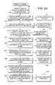
- FIG. 2 is an exemplary method for analyzing computer hardware alarms in a digital cross-connect system
- FIG. 3 is an exemplary screen of alarms in a digital cross-connect system
- FIG. 4 is an exemplary screen of the types of alarm status that may be analyzed in a digital cross-connect system
- FIG. 5 is an exemplary screen of the types of alarms that may be analyzed
- FIG. 6 is an exemplary screen of a prompt requiring a user to specify the minimum number of times a piece of hardware must appear in the hardware paths to be added to a list of suspect hardware;
- FIG. 7 is an exemplary screen displaying a list of suspect hardware.
- the present invention provides a system and method for analyzing hardware alarms in a telecommunications cross-connect system.
- FIG. 1 an exemplary digital cross-connect system for practicing the embodiment of the present invention is depicted and referenced generally by numeral 100 .
- Telephone calls 110 including long distance telephone calls and network transmissions 111 are placed and are converted into signal data.
- the signal data travels to digital cross-connect system (DCS) 112 .
- DCS 112 provides direct and cross-connections of telephone calls and network transmissions.
- signal data enters via inbound port 114 and is “cross-connected.”
- Types of digital cross-connect systems that may be used include, but are not limited to, digital cross-connect systems sold under the name of Alcatel® CS1L and Alcatel® CS1.
- Hardware/cards 116 may include, but are not limited to, Unit Controller (UC) cards, Digital Matrix Multiplexing (DMUX) cards, Digital Matrix Large (DML) cards and Digital Matrix Interface (DMIF) cards.
- UC Unit Controller
- DMUX Digital Matrix Multiplexing
- DML Digital Matrix Large
- DMIF Digital Matrix Interface
- Signal data degradation may occur as the signal data travels through hardware/cards 116 of cross-connecting system 112 . If the signal data is degraded, the system will be down (i.e. the caller cannot use the Internet and/or cannot make outbound calls). These alarms affect customer data because they are an indication of bad signal data integrity across cross-connect system 112 . If the signal data degradation in hardware/cards 116 occurs, technicians are notified of the degradation by an alarm at outbound port 117 . Two of the most common alarms in the hardware/cards 116 in cross-connect system 112 include path and parity alarms. A path alarm occurs when there is a problem or error in the physical route a telecommunication signal data follows.
- Examples of things that may cause a path alarm include, but are not limited to, a disconnection or a blown cable fuse in the power supply.
- a parity alarm occurs when the check character or bit appended to the original contents of a data stream is changed from the original transmission while traveling through hardware/cards 116 of the DCS 112 .
- the following method and system for analyzing path and parity alarms saves the control center technician time in troubleshooting one of the most common alarms that occur in a digital cross-connect system.
- step 200 the system displays alarms in the DCS system. This is illustrated by the exemplary screen of 3.
- step 205 the system then prompts the user to select the alarm status to be analyzed.
- FIG. 4 is an exemplary screen of the types of alarm status that may be analyzed.
- the alarm status to be analyzed may include, but is not limited to, standing alarms 400 , rolling alarms 402 , or long messages 404 .
- Standing alarms are alarms posted to the alarm log but have not cleared.
- Rolling alarms are alarms that post to the alarm log, are cleared shortly thereafter, and are posted again to the alarm log. Examples of a rolling alarm are:
- the system receives the user's selection of alarm status to be analyzed in step 210 , and stores the alarm status in step 212 .
- the alarm status and other information obtained throughout this description may be stored in a table, text file or any other acceptable manner.
- the system captures the alarm data log for the specified alarm status received and stores the captured alarm data log in step 213 .
- FIG. 5 is an exemplary screen of the types of alarms that may be analyzed.
- the types of alarms to be analyzed may include, but is not limited to, Parity A 500 , Parity B 502 , Path A 504 or Path B 506 .
- Path and parity alarms in the DCS may occur on Matrix A or Matrix B.
- a matrix moves calls from one input to the desired output.
- the matrices are on separate physical shelves for moving calls and are labeled A and B.
- the system receives the type of alarm to be analyzed in step 214 and stores the specified alarm type in step 215 .
- the system accesses the alarm data log stored in step 213 for the specified alarm type to determine the specified alarm data to be analyzed.
- the specified alarm data then is stored in a table in step 218 .
- step 220 the system analyzes the specified alarm data stored in step 218 to determine the outbound port(s) in alarm.
- the outbound port information determined in step 220 is stored in a table in step 222 .
- the system determines outbound port 190 is in alarm.
- step 224 the system determines the mapping on all 24 DS0 channels for the mapping of any and all outbound ports having the specified trouble. The following is an example of mapping for outbound port 190 that is in alarm:
- Each set of seven digits represents one of the 24 channels of the DS0. In this example, only four channels are mapped. In other cases, all 24 channels may be mapped and may be mapped to the same or different inbound ports. Furthermore, if additional outbound ports were in alarm besides just outbound port 190 , the system will determine the mapping on all 24 DS0 channels for any additional outbound ports in alarm. In step 226 , the system stores the outbound port mapping information.
- step 228 the system analyzes the outbound porting mapping information stored in step 226 to determine the inbound ports mapped to the outbound port(s) in alarm. Using the above example, all four channels are mapped to inbound 1167 .
- the inbound port information is stored in step 230 .
- step 232 the system accesses hardware information and in step 234 , utilizes the hardware information to determine each piece of hardware (hardware path) the data travels through from each inbound port to the outbound port(s) in alarm.
- This hardware information may be the form of a table, chart or stored information regarding the hardware setup for a particular DCS system. For example, using the unit chart of Table 1, the system determines the hardware/cards of the hardware path the signal data has traveled through from in bound port 1167 to outbound port 190 .
- INB 1167 UC 83 DMIF 13 UP DML 7 DMUX 1 DMIF 03 UC 13 OTB 0190 LW.
- the rolling parity A alarm occurring from inbound port 1167 to outbound port 190 may be occurring in one of the pieces of hardware listed above (Inbound Unit Controller Card 83, Inbound DMIF card 13, Digital Matrix Large Card 7, etc).
- Inbound Unit Controller Card 83 Inbound DMIF card 13, Digital Matrix Large Card 7, etc.
- the system would determine that inbound port 1167 on Matrix A is mapped to unit controller card 83, DMIF card 13 and DML card 5 or 7.
- Outbound port 190 is mapped to DMIF card 03, UC card 13 and DML card 1 or 7.
- the DML card in the hardware path for inbound 1167 and outbound port 190 is 7 because it is common to both the inbound and outbound port.
- the DMUX card 1 is always in the hardware path for alarms occurring on Matrix A and DMUX card 2 for alarms on Matrix B.
- DMUX 1 is part of the hardware path for this example. If more than one outbound port was in alarm, or if outbound port 190 was mapped to more than one other inbound port, then the number of paths and possible hardware causing the alarm will increase.
- the system stores the hardware path information in step 236 .
- step 237 the system prompts the user to specify the minimum number of times a piece of hardware should appear in the different paths to be added to a list of suspect hardware. The prompt is illustrated in FIG. 6 .
- step 238 the system receives the user's input specifying the minimum number of times a piece of hardware should appear.
- step 240 the system then analyzes the hardware paths and determines any pieces of hardware that occur the minimum number of specified times.
- step 242 the system displays all hardware that occurs the minimum number of specified times. Continuing the above example, the user specifies the minimum number of times a piece of hardware should occur is once. An exemplary screen of hardware that occurs at least once in this hardware path/set of hardware paths is shown in FIG. 7 .
- the present invention provides a system and method for analyzing hardware alarms in a telecommunications digital cross-connect system.
- the present invention also relates to system and method for automating the process of analyzing hardware failures that cause path and parity alarms in a telecommunications digital cross-connect system such as, but not limited to, digital cross-connect systems sold under the name of Alcatel® CS1 and CS1L systems.
Abstract
Description
- *09:48:02 96,55 ALM MN
PTY A NPC 190 COMP; and - I09:48:03 96,56 ALM IDLD
PTY A NPC 190 COMPL.
| 1167017 | 1167018 | 1167019 | 1167020 | 0000000 | 0000000 | 0000000 |
| 0000000 | ||||||
| 0000000 | 0000000 | 0000000 | 0000000 | 0000000 | 0000000 | 0000000 |
| 0000000 | ||||||
| 0000000 | 0000000 | 0000000 | 0000000 | 0000000 | 0000000 | 0000000 |
| 0000000 | ||||||
| TABLE 1 | |||||
| Unit | |||||
| Controller | Inbound | Outbound | |||
| Cards | Port | DMIF | DML | DML | |
| UNIT | A/B | Number | A/B | A | B | A | B |
| 1 | 1,2 | 1-28 | 1,2 | 1,3 | 2,4 | 1,7 | 2,8 |
| 2 | 3,4 | 29-56 | 1,2 | 1,3 | 2,4 | 1,7 | 2,8 |
| 3 | 5,6 | 57-84 | 1,2 | 1,3 | 2,4 | 1,7 | 2,8 |
| 4 | 7,8 | 85-112 | 1,2 | 1,3 | 2,4 | 1,7 | 2,8 |
| 5 | 9,10 | 113-140 | 1,2 | 1,3 | 2,4 | 1,7 | 2,8 |
| 6 | 11,12 | 141-168 | 1,2 | 1,3 | 2,4 | 1,7 | 2,8 |
| 7 | 13,14 | 169-196 | 3,4 | 1,3 | 2,4 | 1,7 | 2,8 |
| 8 | 15,16 | 197-224 | 3,4 | 1,3 | 2,4 | 1,7 | 2,8 |
| 9 | 17,18 | 225-252 | 3,4 | 1,3 | 2,4 | 1,7 | 2,8 |
| 10 | 19,20 | 253-280 | 3,4 | 1,3 | 2,4 | 1,7 | 2,8 |
| 11 | 21,22 | 281-308 | 3,4 | 1,3 | 2,4 | 1,7 | 2,8 |
| 12 | 23,24 | 309-336 | 3,4 | 1,3 | 2,4 | 1,7 | 2,8 |
| 13 | 25,26 | 337-364 | 5,6 | 1,3 | 2,4 | 1,7 | 2,8 |
| 14 | 27,28 | 365-392 | 5,6 | 1,3 | 2,4 | 1,7 | 2,8 |
| 15 | 29,30 | 393-420 | 5,6 | 1,3 | 2,4 | 1,7 | 2,8 |
| 16 | 31,32 | 421-448 | 5,6 | 1,3 | 2,4 | 1,7 | 2,8 |
| 17 | 33,34 | 449-476 | 5,6 | 1,3 | 2,4 | 1,7 | 2,8 |
| 18 | 35,36 | 477-504 | 5,6 | 1,3 | 2,4 | 1,7 | 2,8 |
| 19 | 37,38 | 505-532 | 7,8 | 1,3 | 2,4 | 1,7 | 2,8 |
| 20 | 39,40 | 533-560 | 7,8 | 1,3 | 2,4 | 1,7 | 2,8 |
| 21 | 41,42 | 561-588 | 7,8 | 1,3 | 2,4 | 1,7 | 2,8 |
| 22 | 43,44 | 589-616 | 7,8 | 1,3 | 2,4 | 1,7 | 2,8 |
| 23 | 45,46 | 617-644 | 7,8 | 1,3 | 2,4 | 1,7 | 2,8 |
| 24 | 47,48 | 645-672 | 7,8 | 1,3 | 2,4 | 1,7 | 2,8 |
| 25 | 49,50 | 673-700 | 9,10 | 5,7 | 6,8 | 3,5 | 4,6 |
| 26 | 51,52 | 701-728 | 9,10 | 5,7 | 6,8 | 3,5 | 4,6 |
| 27 | 53,54 | 729-756 | 9,10 | 5,7 | 6,8 | 3,5 | 4,6 |
| 28 | 55,56 | 757-784 | 9,10 | 5,7 | 6,8 | 3,5 | 4,6 |
| 29 | 57,58 | 785-812 | 9,10 | 5,7 | 6,8 | 3,5 | 4,6 |
| 30 | 59,60 | 813-840 | 9,10 | 5,7 | 6,8 | 3,5 | 4,6 |
| 31 | 61,62 | 841-868 | 11,12 | 5,7 | 6,8 | 3,5 | 4,6 |
| 32 | 63,64 | 869-896 | 11,12 | 5,7 | 6,8 | 3,5 | 4,6 |
| 33 | 65,66 | 897-924 | 11,12 | 5,7 | 6,8 | 3,5 | 4,6 |
| 34 | 67,68 | 925-952 | 11,12 | 5,7 | 6,8 | 3,5 | 4,6 |
| 35 | 69,70 | 953-980 | 11,12 | 5,7 | 6,8 | 3,5 | 4,6 |
| 36 | 71,72 | 981-1008 | 11,12 | 5,7 | 6,8 | 3,5 | 4,6 |
| 37 | 73,74 | 1009-1036 | 13,14 | 5,7 | 6,8 | 3,5 | 4,6 |
| 38 | 75,76 | 1037-1064 | 13,14 | 5,7 | 6,8 | 3,5 | 4,6 |
| 39 | 77,78 | 1065-1092 | 13,14 | 5,7 | 6,8 | 3,5 | 4,6 |
| 40 | 79,80 | 1093-1120 | 13,14 | 5,7 | 6,8 | 3,5 | 4,6 |
| 41 | 81,82 | 1121-1148 | 13,14 | 5,7 | 6,8 | 3.5 | 4,6 |
| 42 | 83,84 | 1149-1176 | 13,14 | 5,7 | 6,8 | 3,5 | 4,6 |
| 43 | 85,86 | 1177-1204 | 15,16 | 5,7 | 6,8 | 3,5 | 4,6 |
| 44 | 87,88 | 1205-1232 | 15,16 | 5,7 | 6,8 | 3,5 | 4,6 |
| 45 | 89,90 | 1233-1260 | 15,16 | 5,7 | 6,8 | 3,5 | 4,6 |
| 46 | 91,92 | 1261-1288 | 15,16 | 5,7 | 6,8 | 3,5 | 4,6 |
| 47 | 93,94 | 1289-1316 | 15,16 | 5,7 | 6,8 | 3,5 | 4,6 |
| 48 | 95,96 | 1317-1344 | 15,16 | 5,7 | 6,8 | 3,5 | 4,6 |
Claims (24)
Priority Applications (1)
| Application Number | Priority Date | Filing Date | Title |
|---|---|---|---|
| US10/352,537 US6885973B1 (en) | 2003-01-28 | 2003-01-28 | Alarm facilitator and method for analyzing computer hardware alarms |
Applications Claiming Priority (1)
| Application Number | Priority Date | Filing Date | Title |
|---|---|---|---|
| US10/352,537 US6885973B1 (en) | 2003-01-28 | 2003-01-28 | Alarm facilitator and method for analyzing computer hardware alarms |
Publications (1)
| Publication Number | Publication Date |
|---|---|
| US6885973B1 true US6885973B1 (en) | 2005-04-26 |
Family
ID=34434734
Family Applications (1)
| Application Number | Title | Priority Date | Filing Date |
|---|---|---|---|
| US10/352,537 Expired - Fee Related US6885973B1 (en) | 2003-01-28 | 2003-01-28 | Alarm facilitator and method for analyzing computer hardware alarms |
Country Status (1)
| Country | Link |
|---|---|
| US (1) | US6885973B1 (en) |
Cited By (2)
| Publication number | Priority date | Publication date | Assignee | Title |
|---|---|---|---|---|
| US20090028131A1 (en) * | 2007-07-26 | 2009-01-29 | Verizon Services Corp. | Test automation for an integrated telephony call management service |
| US20140043963A1 (en) * | 2008-10-30 | 2014-02-13 | Verizon Patent And Licensing Inc. | Method and system for determining alternate paths |
Citations (5)
| Publication number | Priority date | Publication date | Assignee | Title |
|---|---|---|---|---|
| US3824597A (en) * | 1970-11-09 | 1974-07-16 | Data Transmission Co | Data transmission network |
| US5239575A (en) * | 1991-07-09 | 1993-08-24 | Schlumberger Industries, Inc. | Telephone dial-inbound data acquisition system with demand reading capability |
| US5784551A (en) * | 1992-09-30 | 1998-07-21 | Siemens Telecommunicazioni S.P.A. | Duplicate control and processing unit for telecommunications equipment |
| US5991264A (en) * | 1996-11-26 | 1999-11-23 | Mci Communications Corporation | Method and apparatus for isolating network failures by applying alarms to failure spans |
| US20040022237A1 (en) * | 1998-11-20 | 2004-02-05 | Level 3 Communications, Inc. | Voice over data telecommunications network architecture |
-
2003
- 2003-01-28 US US10/352,537 patent/US6885973B1/en not_active Expired - Fee Related
Patent Citations (5)
| Publication number | Priority date | Publication date | Assignee | Title |
|---|---|---|---|---|
| US3824597A (en) * | 1970-11-09 | 1974-07-16 | Data Transmission Co | Data transmission network |
| US5239575A (en) * | 1991-07-09 | 1993-08-24 | Schlumberger Industries, Inc. | Telephone dial-inbound data acquisition system with demand reading capability |
| US5784551A (en) * | 1992-09-30 | 1998-07-21 | Siemens Telecommunicazioni S.P.A. | Duplicate control and processing unit for telecommunications equipment |
| US5991264A (en) * | 1996-11-26 | 1999-11-23 | Mci Communications Corporation | Method and apparatus for isolating network failures by applying alarms to failure spans |
| US20040022237A1 (en) * | 1998-11-20 | 2004-02-05 | Level 3 Communications, Inc. | Voice over data telecommunications network architecture |
Non-Patent Citations (1)
| Title |
|---|
| Hatonen et al., 'Knowledge Discovery from Telecommunication Network Alarm Databases', Dec. 1996, IEEE Article, pp. 115-122. * |
Cited By (4)
| Publication number | Priority date | Publication date | Assignee | Title |
|---|---|---|---|---|
| US20090028131A1 (en) * | 2007-07-26 | 2009-01-29 | Verizon Services Corp. | Test automation for an integrated telephony call management service |
| US8861379B2 (en) * | 2007-07-26 | 2014-10-14 | Verizon Patent And Licensing Inc. | Test automation for an integrated telephony call management service |
| US20140043963A1 (en) * | 2008-10-30 | 2014-02-13 | Verizon Patent And Licensing Inc. | Method and system for determining alternate paths |
| US9426056B2 (en) * | 2008-10-30 | 2016-08-23 | Verizon Patent And Licensing Inc. | Method and system for determining alternate paths |
Similar Documents
| Publication | Publication Date | Title |
|---|---|---|
| US8014294B2 (en) | System, apparatus and method for devices tracing | |
| CN100479385C (en) | Integral maintaining method and system for multi-equipment | |
| US7441157B2 (en) | System and method for generating a chronic circuit report for use in proactive maintenance of a communication network | |
| CA2343695C (en) | Tree hierarchy and description for generated logs | |
| DE69634109T2 (en) | A method for preventing persistent routing of a call between exchanges due to a translation error | |
| US6885973B1 (en) | Alarm facilitator and method for analyzing computer hardware alarms | |
| US6922465B1 (en) | Method and system for reporting events in telecommunication networks | |
| US5815565A (en) | Service evaluation system and method for a telephonic switch | |
| CN1006436B (en) | Inter-network connection system | |
| US5450468A (en) | Method of rapidly assessing damage to outside loop plant | |
| CN108710553B (en) | System and method for detecting reliability of application server | |
| US20080175370A1 (en) | Method for dial plan parsing and a system incorporating the same | |
| US7185221B1 (en) | Method and system for signaling a system fault | |
| US7804939B2 (en) | Methods and systems for correcting cross-connect assignments | |
| CN108632053B (en) | Service information processing method and device | |
| KR20070079417A (en) | Method for identifying trk of call | |
| US7293023B1 (en) | Method for evaluating data in elements of a communications network | |
| CA2383045A1 (en) | Selecting ipx/igx nodes in a multi-domain environment | |
| CN102469221B (en) | IP (Internet Protocol) telephone call processing method and system as well as IP telephone and voice server | |
| US7020247B1 (en) | Methods and systems for automated target error checking | |
| US7486778B2 (en) | Method for automatically tracing interface for exchange and access network | |
| CN102131006A (en) | Speech equipment accessing method and device | |
| US20050131720A1 (en) | Methods and systems of span design | |
| EP1460859A1 (en) | Method, system and apparatus for managing signaling connections in a telecommunications network | |
| CN100488262C (en) | A method for implementing route balancing based on SPC exchange |
Legal Events
| Date | Code | Title | Description |
|---|---|---|---|
| AS | Assignment |
Owner name: SPRINT COMMUNICATIONS COMPANY L.P., KANSAS Free format text: ASSIGNMENT OF ASSIGNORS INTEREST;ASSIGNOR:MAYHAN, HEATHER M.;REEL/FRAME:013709/0607 Effective date: 20030128 |
|
| FPAY | Fee payment |
Year of fee payment: 4 |
|
| FPAY | Fee payment |
Year of fee payment: 8 |
|
| REMI | Maintenance fee reminder mailed | ||
| AS | Assignment |
Owner name: DEUTSCHE BANK TRUST COMPANY AMERICAS, NEW YORK Free format text: GRANT OF FIRST PRIORITY AND JUNIOR PRIORITY SECURITY INTEREST IN PATENT RIGHTS;ASSIGNOR:SPRINT COMMUNICATIONS COMPANY L.P.;REEL/FRAME:041895/0210 Effective date: 20170203 |
|
| LAPS | Lapse for failure to pay maintenance fees | ||
| STCH | Information on status: patent discontinuation |
Free format text: PATENT EXPIRED DUE TO NONPAYMENT OF MAINTENANCE FEES UNDER 37 CFR 1.362 |
|
| FP | Lapsed due to failure to pay maintenance fee |
Effective date: 20170426 |
|
| AS | Assignment |
Owner name: SPRINT COMMUNICATIONS COMPANY L.P., KANSAS Free format text: TERMINATION AND RELEASE OF FIRST PRIORITY AND JUNIOR PRIORITY SECURITY INTEREST IN PATENT RIGHTS;ASSIGNOR:DEUTSCHE BANK TRUST COMPANY AMERICAS;REEL/FRAME:052969/0475 Effective date: 20200401 Owner name: DEUTSCHE BANK TRUST COMPANY AMERICAS, NEW YORK Free format text: SECURITY AGREEMENT;ASSIGNORS:T-MOBILE USA, INC.;ISBV LLC;T-MOBILE CENTRAL LLC;AND OTHERS;REEL/FRAME:053182/0001 Effective date: 20200401 |
|
| AS | Assignment |
Owner name: SPRINT SPECTRUM LLC, KANSAS Free format text: RELEASE BY SECURED PARTY;ASSIGNOR:DEUTSCHE BANK TRUST COMPANY AMERICAS;REEL/FRAME:062595/0001 Effective date: 20220822 Owner name: SPRINT INTERNATIONAL INCORPORATED, KANSAS Free format text: RELEASE BY SECURED PARTY;ASSIGNOR:DEUTSCHE BANK TRUST COMPANY AMERICAS;REEL/FRAME:062595/0001 Effective date: 20220822 Owner name: SPRINT COMMUNICATIONS COMPANY L.P., KANSAS Free format text: RELEASE BY SECURED PARTY;ASSIGNOR:DEUTSCHE BANK TRUST COMPANY AMERICAS;REEL/FRAME:062595/0001 Effective date: 20220822 Owner name: SPRINTCOM LLC, KANSAS Free format text: RELEASE BY SECURED PARTY;ASSIGNOR:DEUTSCHE BANK TRUST COMPANY AMERICAS;REEL/FRAME:062595/0001 Effective date: 20220822 Owner name: CLEARWIRE IP HOLDINGS LLC, KANSAS Free format text: RELEASE BY SECURED PARTY;ASSIGNOR:DEUTSCHE BANK TRUST COMPANY AMERICAS;REEL/FRAME:062595/0001 Effective date: 20220822 Owner name: CLEARWIRE COMMUNICATIONS LLC, KANSAS Free format text: RELEASE BY SECURED PARTY;ASSIGNOR:DEUTSCHE BANK TRUST COMPANY AMERICAS;REEL/FRAME:062595/0001 Effective date: 20220822 Owner name: BOOST WORLDWIDE, LLC, KANSAS Free format text: RELEASE BY SECURED PARTY;ASSIGNOR:DEUTSCHE BANK TRUST COMPANY AMERICAS;REEL/FRAME:062595/0001 Effective date: 20220822 Owner name: ASSURANCE WIRELESS USA, L.P., KANSAS Free format text: RELEASE BY SECURED PARTY;ASSIGNOR:DEUTSCHE BANK TRUST COMPANY AMERICAS;REEL/FRAME:062595/0001 Effective date: 20220822 Owner name: T-MOBILE USA, INC., WASHINGTON Free format text: RELEASE BY SECURED PARTY;ASSIGNOR:DEUTSCHE BANK TRUST COMPANY AMERICAS;REEL/FRAME:062595/0001 Effective date: 20220822 Owner name: T-MOBILE CENTRAL LLC, WASHINGTON Free format text: RELEASE BY SECURED PARTY;ASSIGNOR:DEUTSCHE BANK TRUST COMPANY AMERICAS;REEL/FRAME:062595/0001 Effective date: 20220822 Owner name: PUSHSPRING, LLC, WASHINGTON Free format text: RELEASE BY SECURED PARTY;ASSIGNOR:DEUTSCHE BANK TRUST COMPANY AMERICAS;REEL/FRAME:062595/0001 Effective date: 20220822 Owner name: LAYER3 TV, LLC, WASHINGTON Free format text: RELEASE BY SECURED PARTY;ASSIGNOR:DEUTSCHE BANK TRUST COMPANY AMERICAS;REEL/FRAME:062595/0001 Effective date: 20220822 Owner name: IBSV LLC, WASHINGTON Free format text: RELEASE BY SECURED PARTY;ASSIGNOR:DEUTSCHE BANK TRUST COMPANY AMERICAS;REEL/FRAME:062595/0001 Effective date: 20220822 |