US6880170B1 - Ingress detection and attenuation - Google Patents
Ingress detection and attenuation Download PDFInfo
- Publication number
- US6880170B1 US6880170B1 US09/473,871 US47387199A US6880170B1 US 6880170 B1 US6880170 B1 US 6880170B1 US 47387199 A US47387199 A US 47387199A US 6880170 B1 US6880170 B1 US 6880170B1
- Authority
- US
- United States
- Prior art keywords
- return path
- ingress
- band
- return
- active sub
- Prior art date
- Legal status (The legal status is an assumption and is not a legal conclusion. Google has not performed a legal analysis and makes no representation as to the accuracy of the status listed.)
- Expired - Fee Related
Links
Images


Classifications
-
- H—ELECTRICITY
- H04—ELECTRIC COMMUNICATION TECHNIQUE
- H04N—PICTORIAL COMMUNICATION, e.g. TELEVISION
- H04N7/00—Television systems
- H04N7/16—Analogue secrecy systems; Analogue subscription systems
- H04N7/173—Analogue secrecy systems; Analogue subscription systems with two-way working, e.g. subscriber sending a programme selection signal
- H04N7/17309—Transmission or handling of upstream communications
-
- H—ELECTRICITY
- H04—ELECTRIC COMMUNICATION TECHNIQUE
- H04N—PICTORIAL COMMUNICATION, e.g. TELEVISION
- H04N7/00—Television systems
- H04N7/10—Adaptations for transmission by electrical cable
- H04N7/102—Circuits therefor, e.g. noise reducers, equalisers, amplifiers
Definitions
- Cable TV systems also known as Community Access Television (CATV) Systems
- CATV Community Access Television
- HFC Hybrid Fiber Coaxial
- voice communications can be carried over an HFC network based either on traditional circuit switched technology or emerging Internet Protocol (IP) standards.
- IP Internet Protocol
- the return path has the undesirable characteristic of accumulating or “funneling” noise towards the head-end.
- the number of subscribers connected to the network is typically greater than 500, and many subscribers can have power dividers (splitters) installed in their homes to allow connection of multiple settops to the cable network.
- the result of the large number of subscribers and the multiple connections in the home is that there are a large number of points on the cable network where undesirable signals can enter the return path.
- the commonly used term for undesirable signals on the cable return path is ingress.
- Ingress is typically, but not limited to, AM shortwave broadcast signals and industrial and atmospheric noise, which can enter on the drop cable connecting the subscriber to the cable plant connection termed the tap, and via the coaxial wiring in the subscriber residence or business location.
- the coaxial wiring used in the home may be of low quality, and will allow ingress because of the low amount of shielding provided with respect to high quality coaxial cable which has a dense braided wire shield which provides high isolation of the center conductor from external electromagnetic fields.
- the coaxial wiring in the home is also typically unterminated, and can act as an antenna since currents generated on the outside of the shield can to some extent couple to the inside of the shield at the unterminated end and subsequently excite the center conductor.
- the accumulation of noise on the return path has adversely limited the use of the return path for many purposes.
- the present invention encompasses a method for detecting the presence of return path ingress and mitigating the return path ingress at a communications gateway located inside or near the subscriber residence or business location.
- the mitigation can be accomplished by either disconnecting the return path at the communications gateway or attenuating the return path signal. Detection of the ingress can occur at the head-end or may occur within the communications gateway.
- the method can be practiced across an entire return frequency band or may take place in an active or inactive sub-band of the return frequency band.
- the detection of ingress can be accomplished by measuring an average return path signal power in the return frequency band and comparing the average return path signal power to a detection threshold. Based on the comparison, a determination that an ingress event is present is declared when the average power exceeds the detection threshold.
- information on channel usage can be obtained and is used to distinguish active sub-bands from inactive sub-bands.
- the presence of ingress can be detected in either the active or inactive sub-bands and mitigated at a location near the subscriber location.
- the channel usage information can be retrieved from the head-end which can include network management equipment and databases which have channel information available.
- the channel usage can be detected automatically at the communications gateway.
- Automatic detection can be accomplished by estimating the Power Spectrum Density (PSD) of a return path signal, correlating the PSD with a set of stored PSDs and determining the peak correlation frequency and frequency band in use.
- PSD Power Spectrum Density
- the present invention can be realized as a communications gateway which has a network side cable connection for transmitting a return path signal onto a cable network, a subscriber side cable connection for receiving the return path signal from the residence or business, an attenuating element for reducing the power in the return path signal, and a control unit for enabling the attenuating element.
- the communications gateway contains a switch which acts as the attenuating element.
- the attenuating element is a notch filter or active electronics capable of attenuating the signal.
- the present invention can also be realized as a communications gateway which contains an acquisition stage for monitoring a return path signal including an analog to digital conversion circuit for digitizing a return path monitoring signal and a processing unit for subsequently processing the return path monitoring signal and determining if the signal exceeds a predetermined threshold.
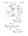
- FIG. 1 illustrates a two-way cable architecture for providing telecommunications services
- FIG. 2A illustrates a communications gateway architecture
- FIG. 2B illustrates a communications gateway architecture with external RF module
- FIG. 3A illustrates a system for acquisition and processing of return path monitoring signals
- FIGS. 3B , 3 C, and 3 D illustrate acquisition stages
- FIG. 4 illustrates full-band ingress monitoring
- FIG. 5 illustrates sub-band ingress monitoring
- FIG. 6 illustrates sub-band ingress monitoring with channel use information
- FIGS. 7A and 7B illustrate active band monitoring
- FIG. 8 illustrates a flow chart for channel usage detection.
- FIGS. 1 through 8 in particular, the apparatus of the present invention is disclosed.
- FIG. 1 illustrates a bi-directional cable system comprising a head-end 100 , a network interface which is represented herein by a Cable Modem Termination System (CMTS) 105 and which may be connected to a channel usage information database 115 .
- CMTS Cable Modem Termination System
- the present system can use any network interface for receiving upstream signals sent by a modem over the HFC network.
- the head-end 100 contains return path receiving equipment which can receive signals from fiber optic cables 108 . In a preferred embodiment, separate cables are used for the transmission of fiber optic signals to a node 120 and for the reception of fiber optic signals transmitted from node 120 to head-end 100 . Return path receiving equipment and methods of detecting return path signals at cable head-ends are well known to those skilled in the art.
- CG Communications Gateway
- BTI Broadband Terminal Interface
- CTU Coaxial Termination Unit
- communications gateway is not intended to be limiting and encompasses equipment which is located on the outside of the home, in the home in a centralized location such as attic, basement or equipment closet, or in another location in the home. Businesses can also use communications gateway type devices for the transmission and reception of data, voice or video signals.
- the residence 152 can also contain a set-top box (STB) 155 which is typically connected to a television 150 and a PC 135 which can contain a cable modem. These units are typically connected through a splitter 145 to the communications gateway 140 which is coupled to the HFC network.
- STB set-top box
- a telephone 147 can be supported by communications gateway 140 which provides traditional voice services by transmitting and receiving telephone signals and converting them to cable compatible signals.
- Telephone service supported by the CG 140 may be circuit switched or Internet Protocol (IP) based telephone service.
- IP Internet Protocol
- signals from the CMTS can be routed to the Internet/private network 110 .
- These signals can be in IP format but may also be carried as circuit switched signals.
- the network used is the traditional Public Switch Telecommunications Network (PSTN).
- PSTN Public Switch Telecommunications Network
- a network management system 160 may also be connected to the Internet/private network 110 and may also be able to access an ingress database 165 .
- Ingress database 165 is used to record ingress events and can be used in conjunction with network management system 160 to establish the thresholds which indicate the presence of unacceptable levels of ingress in residence 152 .
- the network management system 160 can also provide alarm readouts, trends or performance reports to a network operator.
- the network management system 160 retrieves spectrum data from CG 140 and performs fault detection analysis on the retrieved spectrum data.
- the network management system can also store the spectrum data in a database for historical trending or other temporal analysis.
- FIG. 2A illustrates an architecture for CG 140 .
- CG 140 contains an RF module 200 which is capable of receiving signals from the drop cable 221 connected to tap 127 and transmitting those signals to an in-home cable 223 which is typically connected to the splitter 145 .
- a bi-directional coupler 210 is used to couple signals from drop cable 221 to a cable modem (CM) port on CG board 220 .
- the RF module permits the transmission of downstream signals to devices in the home and at the same time allows return path signals to be transmitted from STB 155 , PC 135 , or other devices in the home which support bi-directional communications over the HFC network.
- the CG 140 contains a communications gateway board (CGB) 220 which can support additional voice services and receive signals from the drop cable 221 through use of a tap 210 .
- CGB communications gateway board
- the CG 140 can support telephone services through use of a Network Interface Module (NIM) 230 which supports phone services through a series of RJ11 jacks 231 .
- NIM Network Interface Module
- the communications gateway also has a data interface which provides data services through RJ45 jack 232 .
- the module contains a diplexer 205 which is used to separate out forward pass signals which are typically in the 50 to 750 MHz range of the spectrum from return path signals, which are typically in the 5 to 42 MHz portion of the spectrum. Diplexing of signals on bi-directional HFC plants is well known to those skilled in the art.
- the RF module 200 contains a forward path attenuator 209 which is used in conjunction with an amplifier 207 to provide the appropriate levels in the forward path.
- a passive monitoring tap 202 is used to extract a portion of the return path signal arriving on in-home cable 223 and directed towards the CGB 220 where a monitoring function is performed.
- An attenuator/switch 203 is used in the RF module 200 to attenuate or remove return path signals when ingress from that location is determined to be unacceptable.
- an amplifier is also present in the return path allowing control of signal levels subsequent to the attenuator/switch 203 .
- the attenuator is realized through the use of an electrically controlled variable resistor.
- active electronics configured for attenuation, such as an operational amplifier configured for less than unity gain and programmable by an external control signal, can be utilized.
- Electrically controlled attenuating elements are well known to those skilled in the art.
- a switch can be utilized in which case the control signal forces opening of the return path and eliminates all signals in the return band that have been generated from devices in the home and have been passed up in-home cable 223 and through diplexer 205 .
- a notch filter can be used in place of the switch to eliminate the frequencies that have a signal level above the threshold.
- upstream power-level equalization is performed by adjusting the upstream attenuator/switch 203 .
- the attenuator/switch 203 is initially set to a value which allows signals transmitted from devices in the residence to be received at the head-end. The following algorithm is periodically used to adjust the attenuator/switch 203 . This procedure can be used both when ingress control is being performed as well as when no ingress control processes are active.
- FIG. 2B illustrates an embodiment in which the RF module 200 is implemented without amplifiers.
- a bi-directional coupler 210 is present for coupling CM signals to and from drop cable 221 .
- a high pass filter 240 is used to bypass downstream signals from attenuator switch 203 which is also present in RF module 200 .
- an upstream directional coupler represented herein as passive tap 202 and a downstream directional coupler 204 are present in the RF module 200 of CG 140 to direct the downstream signal to CG board 220 for ingress monitoring purposes.
- the passive tap 202 is used to capture ingress from the home contained in the 5-42 MHz band while the downstream DC 204 captures ingress coming from the tap within the same frequency range.
- a switch 206 is placed at the ingress monitoring input of CG board 220 to time-sequence the outputs of DC 204 and passive tap 202 .
- the downstream DC 204 allows detecting wideband ingress which typically enters the plant after the communication gateway 140 .
- FIG. 3A illustrates one embodiment of CG board 220 .
- an acquisition stage 310 receives signals from an RF module/tap which, referring to FIGS. 2A and 2B , is generated by passive tap 202 .
- the acquisition stage 310 is connected to a Digital Signal Processing (DSP) unit 320 which in addition to providing voice and data services can be used to process return path information to determine if ingress is present and at an unacceptable level.
- DSP 320 is coupled to a Random Access Memory (RAM) 340 which is further coupled to a microprocessor 330 .
- a power estimator 300 is utilized in conjunction with acquisition stage 310 to determine the presence of ingress.
- Microprocessor 330 utilizes information from either power estimator 300 or DSP 320 to determine that ingress is unacceptable and to generate an ingress control signal which is used to attenuate the return path signals or open the switch.
- the return path signals are monitored at head-end 100 to determine if the ingress levels are unacceptable. If so, the CMTS 105 or other head-end equipment can issue a control signal to CG 140 for disconnection or attenuation of the return path.
- the head-end 100 may selectively disconnect residences in an effort to determine which home is the source of ingress, or may work in conjunction with CG 140 to determine if the return path signal from that particular residence should be disconnected or attenuated.
- transceiver 350 is utilized for communications over the HFC network.
- transceiver 350 is based on the Data Over Cable System Interface Specification DOCSIS specification and can be realized using a number of commercially available chips including those produced by the Broadcom Corporation.
- Transceivers for communications over bi-directional HFC networks are well known to those skilled in the art.
- the DSP 320 in addition to performing voice processing for telephony services and other related tasks, can also host a digital implementation of the power estimator module.
- the DSP 320 can run various algorithms using assembly language, C code or other programming languages supported by the DSP.
- the microprocessor 330 can direct the switch to isolate the line when the power exceeds the detection threshold either for a single event or for a predetermined number of ingress events.
- the microprocessor is connected to Random Access Memory (RAM) 340 which may contain data relative to the operation of the CG 140 and the in-home devices.
- the data may include information regarding the number of STB 155 and PCs 135 with cable modems in the home, the channels which these devices use, and the expected power levels. This information can be obtained from a network management system 160 and can be downloaded to the communications gateway via downstream channels in the cable system. When this information is present, the threshold can be calculated based on the expected transmissions from the in-home devices, rather than the worse case values discussed above.
- FIG. 3B illustrates one embodiment of acquisition stage 310 .
- the return path signal from passive tap 202 is processed by a band-pass input filter 360 and subsequently by an analog to digital conversion stage (A/D) 370 which digitizes the signal for subsequent processing by DSP 320 .
- A/D analog to digital conversion stage
- a downconversion technique is illustrated in which signals from passive tap 202 are received by a band-pass input filter 360 and subsequently downconverted using a mixer 380 in conjunction with a local oscillator 385 .
- the downconverted signal is passed through an intermediate frequency filter 375 and to an analog to digital (A/D) converter 370 .
- A/D analog to digital
- An advantage of this embodiment is that different sections of the return path spectrum can be digitized. For example, if IF filter 375 corresponds to a particular sub-band, that sub-band can be digitized and processed for subsequent determination of ingress. By varying the frequency of local oscillator 385 it is possible to select which sub-band will be examined.
- IF filter 375 is programmable such that the sub-bands can be varied in width. This can be useful when sub-bands vary in width from narrow bands on the order of kilohertz wide to wide return bands which may be 2 MHz or more wide.
- FIG. 3D illustrates the use of a variable band-pass filter 390 in conjunction with A/D converter 370 .
- the variable band-pass filter is controlled both in frequency and width to allow direct digitization of the band of interest.
- FIG. 4A illustrates the monitoring of power over a contiguous section of the return band which contains several active channels.
- power estimator 300 estimates the power over a certain bandwidth ⁇ f, determined by microprocessor 330 .
- the power is measured over the 37 MHz band.
- Power estimator 300 can be implemented using a nonlinear (e.g. squaring) function and a low-pass filter to average the power over a period of time T.
- a diode can be used for the nonlinear function and an RC circuit can serve as an integrator.
- Digital implementations are also possible and are based on using an FFT to obtain the PSD of the in-home signal.
- the averaging time is set to a value such that T • ⁇ f >>1.
- T the duration of the signal to be monitored.
- the pulse duration is between 0.1 to 1 ⁇ sec for approximately 95% of impulse events, and between 1 to 10 ⁇ sec for the remaining impulse events.
- Narrowband ingress typically extends to several milliseconds and occupies a bandwidth on the order of kHz.
- FIG. 4A illustrates monitoring of the return path over a monitoring band 404 .
- monitoring band 404 will be 5 to 42 MHz.
- An ingress signal 400 is along with a STB signal 410 , and a CM signal 420 .
- An ingress detection threshold 402 is established, based on the well known general characteristics of ingress, the specific characteristics of ingress for that plant, or a combination of the two.
- the ingress detection threshold 402 may change over time depending on the characteristics of the plant and the services in place. As an example, if more services are utilized the ingress detection threshold 402 may be lowered as compared to an initial value, since ingress may be more critical than when the services provided were minimal or at a low penetration rate.
- ingress detection threshold 402 is established in head-end 100 and transmitted to communication gateway 140 .
- communication gateway 140 establishes ingress detection threshold 402 locally.
- ingress detection threshold 402 can vary over time.
- Ingress database 165 can be utilized to determine an appropriate ingress detection threshold based on historical ingress data.
- historical ingress data can be combined with information regarding channel usage, which is available in channel usage information database 115 , to determine the appropriate ingress detection threshold.
- the ingress power density over the monitored band 440 can be calculated. When the ingress power density over the monitored band 440 does not exceed ingress detection threshold 402 , no action is necessary. When the ingress power density over the monitored band 440 exceeds the ingress detection threshold 402 , the return path signal can be attenuated, or the return path can be opened through use of a switch to eliminate the ingress.
- a CM can transmit up to 58 dBmV within a bandwidth of 3 MHz and an STB can transmit up to 60 dBmV within 150 kHz. If the transmit power for these devices is lowered from the maximum transmit power by 10 dB, the worst case threshold can be calculated as the estimated PSD from these data sources over the entire return path.
- FIGS. 5A and 5B illustrate sub-band monitoring, in which ingress is monitored within monitoring bands 424 .
- These monitoring bands can correspond to DOCSIS channels, ranging from 200 kHz to 3.2 MHz, or can be set to a bandwidth which is sufficiently wide to permit rapid acquisition of the power spectral density but narrow enough to resolve a portion of the return band.
- the ingress power within monitoring bands 500 is measured, and when the ingress power density is greater than the ingress detection threshold, an unacceptable ingress event 510 is declared. Unacceptable ingress event 510 indicates that an unacceptable level of ingress is present in the monitoring bands 500 .
- FIGS. 6A and 6B illustrate the detection of ingress with further discrimination between used and unused bands.
- used bands 610 are distinguished from unused bands 600 , with unused bands 600 not containing any return path signals.
- the advantage of this embodiment is that an ingress detection threshold within used bands 610 can be established which is different than the ingress detection threshold within unused bands 600 .
- unacceptable ingress events in used bands 620 are distinguished from unacceptable ingress events in unused bands 630 .
- the different ingress detection thresholds are established based on the expected power levels in the used bands and the allowable ingress levels as determined with respect to the return path signal levels.
- FIG. 7A illustrates the monitoring of active channels 710 in a return frequency band 700 .
- the communications gateway only monitors channels which have been identified as having return path traffic.
- channels may be identified as active, and the ingress monitoring techniques previously discussed used to determine if there are unacceptable levels of ingress on these channels.
- Information regarding which channels are in use may be obtained from a number of sources, including the CMTS 105 at head-end 100 , or by the CMTS 105 in conjunction with the channel usage information database 115 .
- the CMTS 105 incorporates channel usage information as part of its operation in allocation of return path bandwidth using the DOCSIS protocol. Since CMTS 105 transmits downstream channel usage information to the CG 140 as part of the DOCSIS protocol, the CG can determine which return path channels are in use and monitor those channels correspondingly. Information regarding the use of return path channels by other in-home devices including STB 155 can also be transmitted to CG 140 , either through DOCSIS or as part of another communication protocol.
- FIG. 7B illustrates the monitoring of an active CG channel 720 in the return frequency band 700 .
- the return channel being actively used by the CG 140 is monitored. Because this channel is likely to contain critical return path payloads carrying voice and data, it is important to maintain the integrity of the active CG channel 720 .
- Information from STB 155 which is being carried on another return channel may not be as critical as the information being carried in the active CG channel 720 , and by monitoring the active CG channel 720 only ingress which is present in the active CG channel 720 will result in disconnection or attenuation of the return path.
- This embodiment offers the advantage that ingress signals at frequencies outside of the active CG channel 720 will not result in disruption of communications in the active CG channel 720 .
- FIG. 8 represents a flowchart for a channel recognition method which can be used to identify active channels in the return frequency band 700 .
- the advantage of this technique is that the CG 140 can automatically identify which channels are in use in the return frequency band 700 and mark them as active channels 710 .
- the method is performed by receiving an in-house signal 800 . This can be accomplished through use of the CG 140 with return path monitoring capability as illustrated in FIG. 2 A.
- the power spectral density (PSD) can be determined in an estimate PSD 810 step. Determination of the PSD can be accomplished through use of DSP 320 as illustrated in FIG. 3 A.
- a correlation calculation step 820 is performed using the PSD determined in step 810 and a stored PSD 825 .
- the stored PSD 825 contains a representation of an expected return path PSD.
- DOCSIS based devices can utilize Quadrature Phase Shift Keying (QPSK) transmission or Quadrature Amplitude Modulation (QAM).
- QPSK Quadrature Phase Shift Keying
- QAM Quadrature Amplitude Modulation
- the spectra for these transmissions, including channel width, can be known a priori and stored as part of stored PSD 825 .
- a determine frequency at peak correlation step 830 is performed, followed by a determine minimum frequency band in use step 840 .
- the limits of the active channel 710 are determined. These limits are used in conjunction with a stored or calculated PSD mask to determine the parameters for monitoring of the return path frequency band 700 .
Landscapes
- Engineering & Computer Science (AREA)
- Multimedia (AREA)
- Signal Processing (AREA)
- Cable Transmission Systems, Equalization Of Radio And Reduction Of Echo (AREA)
Abstract
Description
-
- Tx_Difference=(Max_Home_Tx_Level
- −Upstream_CG_Path_Loss
- −Home_Path_Loss
- −CM_Tx_Level
- +CM_Path_Loss
- +Max_Channel_Band_Delta
- −Bypass_Calc_Error_Margin);
where (Max_Home_Tx_Level−Upstream_CG_Path_Loss−Home_Path_Loss) is the maximum home device signal level received at the drop interface, (CM_Tx_Level−CM_Path_Loss) is the CG Cable Modem (CM) transmit level at the drop interface, Max_Channel—Band_Delta is the difference in CG CM channel bandwidth and the maximum CM channel bandwidth of 3.2 MHz and Bypass_Calc_Error_Margin is an offset value. Tx_Difference is the upstream attenuation value and is such that the in-home device transmitted signal power density, after losses in the home and thecommunication gateway 140, is received at the drop interface at a level relatively equivalent to theCG 140 CM transmit level at the drop interface. Such power level equalization limits ingress coming from the home and entering the cable plant, thus reducing any high ingress levels.
- Tx_Difference=(Max_Home_Tx_Level
Claims (12)
Priority Applications (1)
| Application Number | Priority Date | Filing Date | Title |
|---|---|---|---|
| US09/473,871 US6880170B1 (en) | 1994-11-30 | 1999-12-28 | Ingress detection and attenuation |
Applications Claiming Priority (5)
| Application Number | Priority Date | Filing Date | Title |
|---|---|---|---|
| US34757394A | 1994-11-30 | 1994-11-30 | |
| US08/709,456 US5881362A (en) | 1994-11-30 | 1996-09-05 | Method of ingress noise reduction in calbe return paths |
| US09/074,851 US6321384B1 (en) | 1994-11-30 | 1998-05-08 | Noise reduction in cable return paths |
| US18393399P | 1999-06-11 | 1999-06-11 | |
| US09/473,871 US6880170B1 (en) | 1994-11-30 | 1999-12-28 | Ingress detection and attenuation |
Related Parent Applications (1)
| Application Number | Title | Priority Date | Filing Date |
|---|---|---|---|
| US09/074,851 Continuation-In-Part US6321384B1 (en) | 1994-11-30 | 1998-05-08 | Noise reduction in cable return paths |
Publications (1)
| Publication Number | Publication Date |
|---|---|
| US6880170B1 true US6880170B1 (en) | 2005-04-12 |
Family
ID=34427020
Family Applications (1)
| Application Number | Title | Priority Date | Filing Date |
|---|---|---|---|
| US09/473,871 Expired - Fee Related US6880170B1 (en) | 1994-11-30 | 1999-12-28 | Ingress detection and attenuation |
Country Status (1)
| Country | Link |
|---|---|
| US (1) | US6880170B1 (en) |
Cited By (36)
| Publication number | Priority date | Publication date | Assignee | Title |
|---|---|---|---|---|
| US20020144292A1 (en) * | 2001-02-19 | 2002-10-03 | Jun Uemura | Bi-directional CATV system, line equipment, center equipment |
| US20030114112A1 (en) * | 2001-12-04 | 2003-06-19 | Jay Strater | Dynamic upstream attenuation for ingress noise reduction |
| US20040261118A1 (en) * | 2003-06-18 | 2004-12-23 | General Instrument Corporation | Narrowband interference and identification and digital processing for cable television return path performance enhancement |
| US20050114879A1 (en) * | 2003-11-20 | 2005-05-26 | General Instrument Corporation | Monitoring signal quality on a cable network |
| US20060248566A1 (en) * | 2004-12-14 | 2006-11-02 | Tibor Urbanek | Amplifier for use with voice over internet protocol signal |
| US20060271986A1 (en) * | 2005-05-23 | 2006-11-30 | Mark Vogel | Methods, gating devices, and computer program products for determining a noise source in a communication network |
| US20070288982A1 (en) * | 2006-06-13 | 2007-12-13 | Comcast Cable Holdings, Llc | Dynamic ingress arrester |
| WO2008156801A2 (en) * | 2007-06-19 | 2008-12-24 | Arcom Digital, Llc. | Method and apparatus for locating network impairments |
| US20100100912A1 (en) * | 2008-10-16 | 2010-04-22 | John Mezzalingua Associates, Inc. | Upstream bandwidth conditioning device between catv distribution system and catv user |
| US20100100921A1 (en) * | 2008-10-16 | 2010-04-22 | John Mezzalingua Associates, Inc. | Dynamically configurable frequency band selection device between catv distribution system and catv user |
| US7739718B1 (en) * | 2002-08-23 | 2010-06-15 | Arris Group, Inc. | System and method for automatically sensing the state of a video display device |
| US20110085586A1 (en) * | 2009-10-09 | 2011-04-14 | John Mezzalingua Associates, Inc. | Total bandwidth conditioning device |
| US20110088077A1 (en) * | 2009-10-09 | 2011-04-14 | John Mezzalingua Associates, Inc. | Downstream bandwidth conditioning device |
| US20110085452A1 (en) * | 2009-10-09 | 2011-04-14 | John Mezzalingua Associates, Inc. | Upstream bandwidth level measurement device |
| US20110085480A1 (en) * | 2009-10-09 | 2011-04-14 | John Mezzalingua Associates, Inc. | Upstream bandwidth conditioning device |
| US20110197071A1 (en) * | 2010-02-05 | 2011-08-11 | Comcast Cable Communications, Llc | Determining Response Signature Commonalities |
| EP2393291A1 (en) * | 2010-06-07 | 2011-12-07 | Angel Iglesias S.A. | Programmable amplifier for television channels |
| US20130088993A1 (en) * | 2011-07-01 | 2013-04-11 | Certusview Technologies, Llc | Cable communication systems and methods employing tdma/atdma qam upstream channels below 20 mhz for increased upstream capacity to support voice and/or data services |
| US8479247B2 (en) | 2010-04-14 | 2013-07-02 | Ppc Broadband, Inc. | Upstream bandwidth conditioning device |
| US8478199B2 (en) | 2009-03-30 | 2013-07-02 | Ppc Broadband, Inc. | Signal conditioning device with attenuated fail-safe bypass |
| US8510782B2 (en) | 2008-10-21 | 2013-08-13 | Ppc Broadband, Inc. | CATV entry adapter and method for preventing interference with eMTA equipment from MoCA Signals |
| US8561125B2 (en) | 2010-08-30 | 2013-10-15 | Ppc Broadband, Inc. | Home network frequency conditioning device and method |
| US20140082686A1 (en) * | 2012-09-20 | 2014-03-20 | Ben Maxson | Characterizing ingress noise |
| US8724681B2 (en) | 2011-06-27 | 2014-05-13 | Jds Uniphase Corporation | Ingress noise localization in a cable network |
| US20140153624A1 (en) * | 2012-12-03 | 2014-06-05 | Comcast Cable Communications, Llc | Noise ingress detection |
| US8949918B2 (en) | 2013-03-15 | 2015-02-03 | Certusview Technologies, Llc | Hybrid fiber-coaxial (HFC) cable communication systems having well-aligned optical and radio-frequency links to facilitate upstream channel plans having high aggregate data capacity |
| US8971394B2 (en) | 2010-02-05 | 2015-03-03 | Comcast Cable Communications, Llc | Inducing response signatures in a communication network |
| US9363469B2 (en) | 2008-07-17 | 2016-06-07 | Ppc Broadband, Inc. | Passive-active terminal adapter and method having automatic return loss control |
| US9380475B2 (en) | 2013-03-05 | 2016-06-28 | Comcast Cable Communications, Llc | Network implementation of spectrum analysis |
| US9444719B2 (en) | 2013-03-05 | 2016-09-13 | Comcast Cable Communications, Llc | Remote detection and measurement of data signal leakage |
| US9634722B2 (en) | 2013-07-03 | 2017-04-25 | Viavi Solutions Inc. | Cable network spectral measurement during upstream packet transmission |
| US9647851B2 (en) | 2008-10-13 | 2017-05-09 | Ppc Broadband, Inc. | Ingress noise inhibiting network interface device and method for cable television networks |
| US10021343B2 (en) | 2010-12-21 | 2018-07-10 | Ppc Broadband, Inc. | Method and apparatus for reducing isolation in a home network |
| US10778266B2 (en) * | 2017-10-06 | 2020-09-15 | Cable Television Laboratories, Inc. | Smart taps |
| US11711138B1 (en) | 2017-10-06 | 2023-07-25 | Cable Television Laboratories, Inc. | Mitigating satellite interference |
| US11910052B2 (en) | 2008-10-21 | 2024-02-20 | Ppc Broadband, Inc. | Entry device for communicating external network signals and in-home network signals |
Citations (30)
| Publication number | Priority date | Publication date | Assignee | Title |
|---|---|---|---|---|
| US3619783A (en) * | 1970-09-30 | 1971-11-09 | H & B Communications Corp | Means for determining television channel use in a community antenna television system |
| US3716806A (en) * | 1971-08-19 | 1973-02-13 | M Zelenz | Signal coupling apparatus utilizing hybrid transformer |
| US3750022A (en) * | 1972-04-26 | 1973-07-31 | Hughes Aircraft Co | System for minimizing upstream noise in a subscriber response cable television system |
| US3924187A (en) | 1974-05-14 | 1975-12-02 | Magnavox Co | Two-way cable television system with enhanced signal-to-noise ratio for upstream signals |
| US4810898A (en) * | 1987-07-17 | 1989-03-07 | Am Communications, Inc. | RF network isolation switch |
| US4928272A (en) * | 1988-05-23 | 1990-05-22 | Matsushita Electric Industrial Co., Ltd. | Two-way CATV system using frequency division multiplexing |
| US4982440A (en) | 1988-04-21 | 1991-01-01 | Videotron Ltee | CATV network with addressable filters receiving MSK upstream signals |
| US5317392A (en) | 1990-12-26 | 1994-05-31 | Nec Corporation | Noise reducing device for up-going signals in bidirectional CATV system |
| US5343158A (en) | 1991-08-28 | 1994-08-30 | U.S. Philips Corporation | Amplifier device for a cable television distribution network |
| US5361394A (en) | 1989-12-19 | 1994-11-01 | Kabushiki Kaisha Toshiba | Upstream signal control apparatus for cable television system |
| US5421030A (en) | 1991-09-17 | 1995-05-30 | Com21, Inc. | Communications system and method for bi-directional communications between an upstream control facility and downstream user terminals |
| US5425027A (en) | 1993-01-04 | 1995-06-13 | Com21, Inc. | Wide area fiber and TV cable fast packet cell network |
| US5428819A (en) * | 1993-04-27 | 1995-06-27 | Motorola, Inc. | Method and apparatus for radio frequency bandwidth sharing among heterogeneous radio communication system |
| US5544164A (en) | 1992-09-29 | 1996-08-06 | Com 21, Inc. | Method and cell based wide area network alternative access telephone and data system |
| US5606725A (en) | 1994-11-29 | 1997-02-25 | Xel Communications, Inc. | Broadband network having an upstream power transmission level that is dynamically adjusted as a function of the bit error rate |
| US5737461A (en) * | 1996-05-09 | 1998-04-07 | Motorola, Inc. | Methods and filter for isolating upstream ingress noise in a bi-directional cable system |
| US5742713A (en) | 1996-10-23 | 1998-04-21 | Motorola, Inc. | Methods and filter for isolating upstream ingress noise in a bi-directional cable system |
| US5745836A (en) | 1995-09-01 | 1998-04-28 | Cable Television Laboratories, Inc. | Undesirable energy suppression system in a contention based communication network |
| US5819159A (en) | 1996-07-25 | 1998-10-06 | At&T Corp | Method for asymmetrically attenuating signals in a transmission system |
| US5835844A (en) * | 1995-12-29 | 1998-11-10 | General Instrument Corporation | Bidirectional CATV system having losses for equalizing upstream communication gain |
| US5845191A (en) | 1996-07-25 | 1998-12-01 | At&T Corp | Method for asymmetrically attenuating signals in a transmission system |
| US5867764A (en) | 1995-09-01 | 1999-02-02 | Cable Television Laboratories, Inc. | Hybrid return gate system in a bidirectional cable network |
| US5881362A (en) | 1994-11-30 | 1999-03-09 | General Instrument Corporation Of Delaware | Method of ingress noise reduction in calbe return paths |
| US5893024A (en) | 1996-08-13 | 1999-04-06 | Motorola, Inc. | Data communication apparatus and method thereof |
| US6094211A (en) * | 1996-08-15 | 2000-07-25 | Com21, Inc. | TV and data cable system ingress noise blocker |
| US6230326B1 (en) * | 1998-07-30 | 2001-05-08 | Nortel Networks Limited | Method and apparatus for initialization of a cable modem |
| US6385773B1 (en) * | 1999-01-07 | 2002-05-07 | Cisco Techology, Inc. | Method and apparatus for upstream frequency channel transition |
| US6567987B1 (en) * | 1999-02-16 | 2003-05-20 | Scientific-Atlanta, Inc. | Digital optical transmitter with improved noise power ratio |
| US6570913B1 (en) * | 1999-04-05 | 2003-05-27 | Cisco Technology, Inc. | Method and apparatus for selecting optimum frequency for upstream data transmission in a network system utilizing cable modems |
| US6574797B1 (en) * | 1999-01-08 | 2003-06-03 | Cisco Technology, Inc. | Method and apparatus for locating a cleaner bandwidth in a frequency channel for data transmission |
-
1999
- 1999-12-28 US US09/473,871 patent/US6880170B1/en not_active Expired - Fee Related
Patent Citations (31)
| Publication number | Priority date | Publication date | Assignee | Title |
|---|---|---|---|---|
| US3619783A (en) * | 1970-09-30 | 1971-11-09 | H & B Communications Corp | Means for determining television channel use in a community antenna television system |
| US3716806A (en) * | 1971-08-19 | 1973-02-13 | M Zelenz | Signal coupling apparatus utilizing hybrid transformer |
| US3750022A (en) * | 1972-04-26 | 1973-07-31 | Hughes Aircraft Co | System for minimizing upstream noise in a subscriber response cable television system |
| US3924187A (en) | 1974-05-14 | 1975-12-02 | Magnavox Co | Two-way cable television system with enhanced signal-to-noise ratio for upstream signals |
| US4810898A (en) * | 1987-07-17 | 1989-03-07 | Am Communications, Inc. | RF network isolation switch |
| US4982440A (en) | 1988-04-21 | 1991-01-01 | Videotron Ltee | CATV network with addressable filters receiving MSK upstream signals |
| US4928272A (en) * | 1988-05-23 | 1990-05-22 | Matsushita Electric Industrial Co., Ltd. | Two-way CATV system using frequency division multiplexing |
| US5361394A (en) | 1989-12-19 | 1994-11-01 | Kabushiki Kaisha Toshiba | Upstream signal control apparatus for cable television system |
| US5317392A (en) | 1990-12-26 | 1994-05-31 | Nec Corporation | Noise reducing device for up-going signals in bidirectional CATV system |
| US5343158A (en) | 1991-08-28 | 1994-08-30 | U.S. Philips Corporation | Amplifier device for a cable television distribution network |
| US5421030A (en) | 1991-09-17 | 1995-05-30 | Com21, Inc. | Communications system and method for bi-directional communications between an upstream control facility and downstream user terminals |
| US5544164A (en) | 1992-09-29 | 1996-08-06 | Com 21, Inc. | Method and cell based wide area network alternative access telephone and data system |
| US5870395A (en) | 1993-01-04 | 1999-02-09 | Com 21, Incorporated | Wide area fiber and tv cable fast packet cell network |
| US5425027A (en) | 1993-01-04 | 1995-06-13 | Com21, Inc. | Wide area fiber and TV cable fast packet cell network |
| US5428819A (en) * | 1993-04-27 | 1995-06-27 | Motorola, Inc. | Method and apparatus for radio frequency bandwidth sharing among heterogeneous radio communication system |
| US5606725A (en) | 1994-11-29 | 1997-02-25 | Xel Communications, Inc. | Broadband network having an upstream power transmission level that is dynamically adjusted as a function of the bit error rate |
| US5881362A (en) | 1994-11-30 | 1999-03-09 | General Instrument Corporation Of Delaware | Method of ingress noise reduction in calbe return paths |
| US5867764A (en) | 1995-09-01 | 1999-02-02 | Cable Television Laboratories, Inc. | Hybrid return gate system in a bidirectional cable network |
| US5745836A (en) | 1995-09-01 | 1998-04-28 | Cable Television Laboratories, Inc. | Undesirable energy suppression system in a contention based communication network |
| US5835844A (en) * | 1995-12-29 | 1998-11-10 | General Instrument Corporation | Bidirectional CATV system having losses for equalizing upstream communication gain |
| US5737461A (en) * | 1996-05-09 | 1998-04-07 | Motorola, Inc. | Methods and filter for isolating upstream ingress noise in a bi-directional cable system |
| US5845191A (en) | 1996-07-25 | 1998-12-01 | At&T Corp | Method for asymmetrically attenuating signals in a transmission system |
| US5819159A (en) | 1996-07-25 | 1998-10-06 | At&T Corp | Method for asymmetrically attenuating signals in a transmission system |
| US5893024A (en) | 1996-08-13 | 1999-04-06 | Motorola, Inc. | Data communication apparatus and method thereof |
| US6094211A (en) * | 1996-08-15 | 2000-07-25 | Com21, Inc. | TV and data cable system ingress noise blocker |
| US5742713A (en) | 1996-10-23 | 1998-04-21 | Motorola, Inc. | Methods and filter for isolating upstream ingress noise in a bi-directional cable system |
| US6230326B1 (en) * | 1998-07-30 | 2001-05-08 | Nortel Networks Limited | Method and apparatus for initialization of a cable modem |
| US6385773B1 (en) * | 1999-01-07 | 2002-05-07 | Cisco Techology, Inc. | Method and apparatus for upstream frequency channel transition |
| US6574797B1 (en) * | 1999-01-08 | 2003-06-03 | Cisco Technology, Inc. | Method and apparatus for locating a cleaner bandwidth in a frequency channel for data transmission |
| US6567987B1 (en) * | 1999-02-16 | 2003-05-20 | Scientific-Atlanta, Inc. | Digital optical transmitter with improved noise power ratio |
| US6570913B1 (en) * | 1999-04-05 | 2003-05-27 | Cisco Technology, Inc. | Method and apparatus for selecting optimum frequency for upstream data transmission in a network system utilizing cable modems |
Cited By (86)
| Publication number | Priority date | Publication date | Assignee | Title |
|---|---|---|---|---|
| US20020144292A1 (en) * | 2001-02-19 | 2002-10-03 | Jun Uemura | Bi-directional CATV system, line equipment, center equipment |
| US7742777B2 (en) * | 2001-12-04 | 2010-06-22 | General Instrument Corporation | Dynamic upstream attenuation for ingress noise reduction |
| US20030114112A1 (en) * | 2001-12-04 | 2003-06-19 | Jay Strater | Dynamic upstream attenuation for ingress noise reduction |
| US7039432B2 (en) * | 2001-12-04 | 2006-05-02 | General Instrument Corporation | Dynamic upstream attenuation for ingress noise reduction |
| US20060148406A1 (en) * | 2001-12-04 | 2006-07-06 | Jay Strater | Dynamic upstream attenuation for ingress noise reduction |
| US7739718B1 (en) * | 2002-08-23 | 2010-06-15 | Arris Group, Inc. | System and method for automatically sensing the state of a video display device |
| US20040261118A1 (en) * | 2003-06-18 | 2004-12-23 | General Instrument Corporation | Narrowband interference and identification and digital processing for cable television return path performance enhancement |
| US7716712B2 (en) * | 2003-06-18 | 2010-05-11 | General Instrument Corporation | Narrowband interference and identification and digital processing for cable television return path performance enhancement |
| US20050114879A1 (en) * | 2003-11-20 | 2005-05-26 | General Instrument Corporation | Monitoring signal quality on a cable network |
| WO2005053303A2 (en) * | 2003-11-20 | 2005-06-09 | General Instrument Corporation | Monitoring signal quality on a cable network |
| WO2005053303A3 (en) * | 2003-11-20 | 2007-06-07 | Gen Instrument Corp | Monitoring signal quality on a cable network |
| US20060248566A1 (en) * | 2004-12-14 | 2006-11-02 | Tibor Urbanek | Amplifier for use with voice over internet protocol signal |
| US20060271986A1 (en) * | 2005-05-23 | 2006-11-30 | Mark Vogel | Methods, gating devices, and computer program products for determining a noise source in a communication network |
| US20070288982A1 (en) * | 2006-06-13 | 2007-12-13 | Comcast Cable Holdings, Llc | Dynamic ingress arrester |
| WO2008156801A3 (en) * | 2007-06-19 | 2009-02-19 | Arcom Digital Llc | Method and apparatus for locating network impairments |
| US8458759B2 (en) | 2007-06-19 | 2013-06-04 | Arcom Digital, Llc | Method and apparatus for locating network impairments |
| WO2008156801A2 (en) * | 2007-06-19 | 2008-12-24 | Arcom Digital, Llc. | Method and apparatus for locating network impairments |
| US20080320541A1 (en) * | 2007-06-19 | 2008-12-25 | Zinevich Victor M | Method and apparatus for locating network impairments |
| US10257462B2 (en) | 2008-07-17 | 2019-04-09 | Ppc Broadband, Inc. | Adapter for a cable-television network |
| US9363469B2 (en) | 2008-07-17 | 2016-06-07 | Ppc Broadband, Inc. | Passive-active terminal adapter and method having automatic return loss control |
| US9769418B2 (en) | 2008-07-17 | 2017-09-19 | Ppc Broadband, Inc. | Passive-active terminal adapter and method having automatic return loss control |
| US9647851B2 (en) | 2008-10-13 | 2017-05-09 | Ppc Broadband, Inc. | Ingress noise inhibiting network interface device and method for cable television networks |
| US10045056B2 (en) | 2008-10-13 | 2018-08-07 | Ppc Broadband, Inc. | Ingress noise inhibiting network interface device and method for cable television networks |
| US10187673B2 (en) | 2008-10-13 | 2019-01-22 | Ppc Broadband, Inc. | Ingress noise inhibiting network interface device and method for cable television networks |
| US20100100912A1 (en) * | 2008-10-16 | 2010-04-22 | John Mezzalingua Associates, Inc. | Upstream bandwidth conditioning device between catv distribution system and catv user |
| US10924811B2 (en) | 2008-10-16 | 2021-02-16 | Ppc Broadband, Inc. | Compensation device for maintaining a desired signal quality in transmitted signals |
| US9271026B2 (en) | 2008-10-16 | 2016-02-23 | Ppc Broadband, Inc. | Dynamically configurable frequency band selection device between CATV distribution system and CATV user |
| US20100100921A1 (en) * | 2008-10-16 | 2010-04-22 | John Mezzalingua Associates, Inc. | Dynamically configurable frequency band selection device between catv distribution system and catv user |
| US8464301B2 (en) | 2008-10-16 | 2013-06-11 | Ppc Broadband, Inc. | Upstream bandwidth conditioning device between CATV distribution system and CATV user |
| US8832767B2 (en) | 2008-10-16 | 2014-09-09 | Ppc Broadband, Inc. | Dynamically configurable frequency band selection device between CATV distribution system and CATV user |
| US10264325B2 (en) | 2008-10-16 | 2019-04-16 | Ppc Broadband, Inc. | System, method and device having teaching and commerce subsystems |
| US11910052B2 (en) | 2008-10-21 | 2024-02-20 | Ppc Broadband, Inc. | Entry device for communicating external network signals and in-home network signals |
| US8510782B2 (en) | 2008-10-21 | 2013-08-13 | Ppc Broadband, Inc. | CATV entry adapter and method for preventing interference with eMTA equipment from MoCA Signals |
| US8478199B2 (en) | 2009-03-30 | 2013-07-02 | Ppc Broadband, Inc. | Signal conditioning device with attenuated fail-safe bypass |
| US20110088077A1 (en) * | 2009-10-09 | 2011-04-14 | John Mezzalingua Associates, Inc. | Downstream bandwidth conditioning device |
| US20110085480A1 (en) * | 2009-10-09 | 2011-04-14 | John Mezzalingua Associates, Inc. | Upstream bandwidth conditioning device |
| US20110085586A1 (en) * | 2009-10-09 | 2011-04-14 | John Mezzalingua Associates, Inc. | Total bandwidth conditioning device |
| US8213457B2 (en) * | 2009-10-09 | 2012-07-03 | John Mezzalingua Associates, Inc. | Upstream bandwidth conditioning device |
| US8516537B2 (en) | 2009-10-09 | 2013-08-20 | Ppc Broadband, Inc. | Downstream bandwidth conditioning device |
| US20110085452A1 (en) * | 2009-10-09 | 2011-04-14 | John Mezzalingua Associates, Inc. | Upstream bandwidth level measurement device |
| US8385219B2 (en) * | 2009-10-09 | 2013-02-26 | John Mezzalingua Associates, Inc. | Upstream bandwidth level measurement device |
| US9602518B2 (en) | 2010-02-05 | 2017-03-21 | Comcast Cable Communications, Llc | Modulation analysis and distortion identification |
| US10187397B2 (en) | 2010-02-05 | 2019-01-22 | Comcast Cable Communications, Llc | Modulation analysis and distortion identification |
| US20110197071A1 (en) * | 2010-02-05 | 2011-08-11 | Comcast Cable Communications, Llc | Determining Response Signature Commonalities |
| US8856535B2 (en) | 2010-02-05 | 2014-10-07 | Comcast Cable Communications, Llc | Determining response signature commonalities |
| US9479515B2 (en) | 2010-02-05 | 2016-10-25 | Comcast Cable Communications, Llc | Identification of a fault |
| US9537680B2 (en) | 2010-02-05 | 2017-01-03 | Comcast Cable Communications, Llc | Inducing response signatures in a communication network |
| US8971394B2 (en) | 2010-02-05 | 2015-03-03 | Comcast Cable Communications, Llc | Inducing response signatures in a communication network |
| US9438605B2 (en) | 2010-02-05 | 2016-09-06 | Comcast Cable Communications, Llc | Determining response signature commonalities |
| US8479247B2 (en) | 2010-04-14 | 2013-07-02 | Ppc Broadband, Inc. | Upstream bandwidth conditioning device |
| EP2393291A1 (en) * | 2010-06-07 | 2011-12-07 | Angel Iglesias S.A. | Programmable amplifier for television channels |
| US8561125B2 (en) | 2010-08-30 | 2013-10-15 | Ppc Broadband, Inc. | Home network frequency conditioning device and method |
| US11070766B2 (en) | 2010-12-21 | 2021-07-20 | Ppc Broadband, Inc. | Method and apparatus for reducing isolation in a home network |
| US10021343B2 (en) | 2010-12-21 | 2018-07-10 | Ppc Broadband, Inc. | Method and apparatus for reducing isolation in a home network |
| US10750120B2 (en) | 2010-12-21 | 2020-08-18 | Ppc Broadband, Inc. | Method and apparatus for reducing isolation in a home network |
| US8724681B2 (en) | 2011-06-27 | 2014-05-13 | Jds Uniphase Corporation | Ingress noise localization in a cable network |
| US8811191B2 (en) | 2011-07-01 | 2014-08-19 | Certusview Technologies, Llc | Iterative mapping methods for ingress mitigation in cable communication systems |
| US8948596B2 (en) | 2011-07-01 | 2015-02-03 | CetusView Technologies, LLC | Neighborhood node mapping methods and apparatus for ingress mitigation in cable communication systems |
| US20130088993A1 (en) * | 2011-07-01 | 2013-04-11 | Certusview Technologies, Llc | Cable communication systems and methods employing tdma/atdma qam upstream channels below 20 mhz for increased upstream capacity to support voice and/or data services |
| US8532488B2 (en) | 2011-07-01 | 2013-09-10 | Certusview Technologies, Llc | Cable communication systems and methods employing QAM upstream channels below 16.4 MHz for increased aggregate deployed upstream capacity to support voice and/or data services |
| US8543003B2 (en) | 2011-07-01 | 2013-09-24 | Certusview Technologies, Llc | Ingress-mitigated cable communication systems and methods having increased upstream capacity for supporting voice and/or data services |
| US9088310B2 (en) | 2011-07-01 | 2015-07-21 | Certusview Technologies, Llc | Cable communication systems and methods employing QAM upstream channels below 16.4 MHz for increased aggregate deployed upstream capacity |
| US9577746B2 (en) | 2011-07-01 | 2017-02-21 | Certusview Technologies, Llc | Methods for ingress remediation in cable communication systems |
| US9019855B2 (en) * | 2011-07-01 | 2015-04-28 | Certusview Technologies, Llc | Cable communication systems and methods employing TDMA/ATDMA QAM upstream channels below 20 MHz for increased upstream capacity to support voice and/or data services |
| US8578437B2 (en) | 2011-07-01 | 2013-11-05 | Certusview Technologies, Llc | Methods for ingress mitigation in cable communication systems involving repair, replacement and/or adjustment of infrastructure elements |
| US8650606B2 (en) | 2011-07-01 | 2014-02-11 | Certusview Technologies, Llc | Cable communication systems and methods employing 256-QAM upstream channels and having increased upstream capacity for supporting voice and/or data services |
| US8806559B2 (en) | 2011-07-01 | 2014-08-12 | Certusview Technologies, Llc | Methods for ingress mitigation in cable communication systems involving repair, replacement and/or adjustment of infrastructure elements |
| US8977132B2 (en) | 2011-07-01 | 2015-03-10 | Certusview Technologies, Llc | Ingress-mitigated RF cable plants and ingress mitigation methods for same |
| US10084538B2 (en) | 2011-07-01 | 2018-09-25 | Certusview Technologies, Llc | Cable communication systems and methods employing 256-QAM upstream channels and having increased upstream capacity for supporting voice and/or data services |
| US10594364B2 (en) * | 2012-09-20 | 2020-03-17 | Viavi Solutions Inc. | Characterizing ingress noise |
| US20140082686A1 (en) * | 2012-09-20 | 2014-03-20 | Ben Maxson | Characterizing ingress noise |
| US9357163B2 (en) * | 2012-09-20 | 2016-05-31 | Viavi Solutions Inc. | Characterizing ingress noise |
| US20160336998A1 (en) * | 2012-09-20 | 2016-11-17 | Viavi Solutions Inc. | Characterizing ingress noise |
| US20140153624A1 (en) * | 2012-12-03 | 2014-06-05 | Comcast Cable Communications, Llc | Noise ingress detection |
| US9015786B2 (en) * | 2012-12-03 | 2015-04-21 | Comcast Cable Communications, Llc | Noise ingress detection |
| US10477422B2 (en) | 2013-03-05 | 2019-11-12 | Comcast Cable Communications, Llc | Network implementation of spectrum analysis |
| US9380475B2 (en) | 2013-03-05 | 2016-06-28 | Comcast Cable Communications, Llc | Network implementation of spectrum analysis |
| US10798597B2 (en) | 2013-03-05 | 2020-10-06 | Comcast Cable Communications, Llc | Network implementation of spectrum analysis |
| US9826424B2 (en) | 2013-03-05 | 2017-11-21 | Comcast Cable Communications, Llc | Network implementation of spectrum analysis |
| US9444719B2 (en) | 2013-03-05 | 2016-09-13 | Comcast Cable Communications, Llc | Remote detection and measurement of data signal leakage |
| US8949918B2 (en) | 2013-03-15 | 2015-02-03 | Certusview Technologies, Llc | Hybrid fiber-coaxial (HFC) cable communication systems having well-aligned optical and radio-frequency links to facilitate upstream channel plans having high aggregate data capacity |
| US9660729B2 (en) | 2013-03-15 | 2017-05-23 | Certusview Technologies, Llc | Cable communication system optical nodes having selectable attenuation values to mitigate distortion of upstream information |
| US9634722B2 (en) | 2013-07-03 | 2017-04-25 | Viavi Solutions Inc. | Cable network spectral measurement during upstream packet transmission |
| US9893764B2 (en) | 2013-07-03 | 2018-02-13 | Viavi Solutions Inc. | Cable network spectral measurement during upstream packet transmission |
| US10778266B2 (en) * | 2017-10-06 | 2020-09-15 | Cable Television Laboratories, Inc. | Smart taps |
| US11711138B1 (en) | 2017-10-06 | 2023-07-25 | Cable Television Laboratories, Inc. | Mitigating satellite interference |
Similar Documents
| Publication | Publication Date | Title |
|---|---|---|
| US6880170B1 (en) | Ingress detection and attenuation | |
| US6915530B1 (en) | Ingress detection and characterization by time/frequency map | |
| US6895043B1 (en) | Method and apparatus for measuring quality of upstream signal transmission of a cable modem | |
| US7742777B2 (en) | Dynamic upstream attenuation for ingress noise reduction | |
| JPH1093605A (en) | Cable network system, its transmission line switching device, subscriber device, adapter device, and mixed noise monitor and analysis device | |
| US6049693A (en) | Upstream ingress noise blocking filter for cable television system | |
| US6556239B1 (en) | Distortion monitoring system for CATV transmission networks | |
| US20020190846A1 (en) | Ingress monitoring device in a broadband communications system | |
| GB2316590A (en) | Data communication apparatus and method thereof | |
| US10764532B2 (en) | Method and system for locating ingress utilizing customer premises equipment | |
| EP3251299B1 (en) | Reverse-direction tap (rdt), remote diagnostic management tool (rdmt), and analyses using the rdt and rdmt | |
| US5742713A (en) | Methods and filter for isolating upstream ingress noise in a bi-directional cable system | |
| US10333616B1 (en) | Detecting burst PIM in downstream at drop | |
| US20030121056A1 (en) | HFC reverse path using an intelligent dynamic switch | |
| US20070083909A1 (en) | RF Return Optical Transmission | |
| US8312496B2 (en) | Measuring the frequency response of a CATV network | |
| US20170019147A1 (en) | Capture and Analysis of Transient Events in Hybrid Fiber-Coaxial (HFC) Networks | |
| WO2010045552A1 (en) | Bandwidth conditioning device | |
| US20020083476A1 (en) | Method and apparatus for reducing the flow of RF noise from subscriber's premise cable systems into the reverse transmission path of two-way cable networks | |
| US20120213083A1 (en) | Home network test circuit | |
| KR101336133B1 (en) | An apparatus for controlling reverse noise in hfc network and the method thereof | |
| US6888883B1 (en) | Method and apparatus for reducing noise leakage from a cable modem | |
| KR100844316B1 (en) | Hfc transmission network monitoring apparatus | |
| EP1354431B1 (en) | Rf bidirectional optical transmission | |
| US20230254443A1 (en) | Passive entry adapter system for a catv network |
Legal Events
| Date | Code | Title | Description |
|---|---|---|---|
| AS | Assignment |
Owner name: GENERAL INSTRUMENT CORPORATION, PENNSYLVANIA Free format text: ASSIGNMENT OF ASSIGNORS INTEREST;ASSIGNORS:KAUFFMAN, MARC W.;BLUM, WILLIAM H.;SHERLOCK, PETER;AND OTHERS;REEL/FRAME:010583/0196;SIGNING DATES FROM 20000221 TO 20000228 |
|
| CC | Certificate of correction | ||
| FPAY | Fee payment |
Year of fee payment: 4 |
|
| FPAY | Fee payment |
Year of fee payment: 8 |
|
| AS | Assignment |
Owner name: MOTOROLA MOBILITY LLC, ILLINOIS Free format text: ASSIGNMENT OF ASSIGNORS INTEREST;ASSIGNOR:GENERAL INSTRUMENT HOLDINGS, INC.;REEL/FRAME:030866/0113 Effective date: 20130528 Owner name: GENERAL INSTRUMENT HOLDINGS, INC., CALIFORNIA Free format text: ASSIGNMENT OF ASSIGNORS INTEREST;ASSIGNOR:GENERAL INSTRUMENT CORPORATION;REEL/FRAME:030764/0575 Effective date: 20130415 |
|
| AS | Assignment |
Owner name: GOOGLE TECHNOLOGY HOLDINGS LLC, CALIFORNIA Free format text: ASSIGNMENT OF ASSIGNORS INTEREST;ASSIGNOR:MOTOROLA MOBILITY LLC;REEL/FRAME:034452/0001 Effective date: 20141028 |
|
| REMI | Maintenance fee reminder mailed | ||
| LAPS | Lapse for failure to pay maintenance fees | ||
| STCH | Information on status: patent discontinuation |
Free format text: PATENT EXPIRED DUE TO NONPAYMENT OF MAINTENANCE FEES UNDER 37 CFR 1.362 |
|
| FP | Lapsed due to failure to pay maintenance fee |
Effective date: 20170412 |