US6844701B2 - Overmodulation systems and methods for induction motor control - Google Patents
Overmodulation systems and methods for induction motor control Download PDFInfo
- Publication number
- US6844701B2 US6844701B2 US10/345,872 US34587203A US6844701B2 US 6844701 B2 US6844701 B2 US 6844701B2 US 34587203 A US34587203 A US 34587203A US 6844701 B2 US6844701 B2 US 6844701B2
- Authority
- US
- United States
- Prior art keywords
- motor
- operation state
- field weakening
- detecting
- flux current
- Prior art date
- Legal status (The legal status is an assumption and is not a legal conclusion. Google has not performed a legal analysis and makes no representation as to the accuracy of the status listed.)
- Expired - Lifetime
Links
Images


Classifications
-
- H—ELECTRICITY
- H02—GENERATION; CONVERSION OR DISTRIBUTION OF ELECTRIC POWER
- H02P—CONTROL OR REGULATION OF ELECTRIC MOTORS, ELECTRIC GENERATORS OR DYNAMO-ELECTRIC CONVERTERS; CONTROLLING TRANSFORMERS, REACTORS OR CHOKE COILS
- H02P23/00—Arrangements or methods for the control of AC motors characterised by a control method other than vector control
- H02P23/0004—Control strategies in general, e.g. linear type, e.g. P, PI, PID, using robust control
Definitions
- the present invention relates generally to systems and methods for directing and controlling the operation of an induction motor.
- the “fuel” powering an induction motor is current.
- This current may be divided into two components, torque current and flux current.
- Torque current may be viewed as that component of the current which generates motive force, or torque.
- Flux current may be viewed as that component of the current which generates magnetic flux in the rotor of the motor.
- Shaft torque and rotor flux are related, with shaft torque proportional to the product of rotor flux and torque current. At high speeds, shaft torque may be calculated using back-EMF voltage.
- overmodulation involves the injection of harmonics into the fundamental current of the motor. These harmonics increase the overall size of the fundamental current. This allows for greater torque production than may be achieved with a pure sine wave drive, given a fixed DC bus voltage.
- overmodulation is that the fundamental current waveform becomes distorted and, as a consequence, nuisance trips of the overcurrent protection result.
- Taught herein are systems and methods which improve the robustness of the overmodulation strategy for controlling an induction motor during high-speed operation. These systems and methods reduce the occurrence of nuisance overcurrent faults by delaying the onset of overmodulation until field weakening has taken effect.
- a method for controlling an induction motor includes detecting a field weakening operation state of the motor, wherein the field weakening operation state is detected when a flux current, I d , in the motor is reduced to a predetermined fraction of its normal, non-voltage limited value.
- the method also includes disabling an overmodulation operation state of the motor before said field weakening operation state is detected and enabling the overmodulation operation state of the motor after said field weakening operation state is detected.
- a system for controlling an induction motor includes means for detecting a field weakening operation state of the motor, wherein the field weakening operation state is detected when a flux current, I d , in the motor is reduced to a predetermined fraction of its normal, non-voltage limited value.
- the system also includes means for disabling an overmodulation operation state of the motor before said field weakening operation state is detected and means for enabling the overmodulation operation state of the motor after said field weakening operation state is detected.
- FIG. 1 is a flow chart of one embodiment of the overmodulation strategy of the present invention, linking the enabling of overmodulation operation of an induction motor to field weakening operation at high speeds.
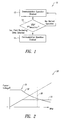
- FIG. 2 is a graph of the relationship between current and voltage before and after field weakening has taken effect, highlighting a “corner point” where current and voltage are at their respective limits.
- FIG. 3 is a functional block diagram of one embodiment of a system for carrying out the overmodulation strategy of the present invention.
- overmodulation allows for the injection of harmonics into the fundamental current of the motor. These harmonics increase the overall size of the fundamental current. This allows for greater torque production than may be achieved with a pure sine wave drive, given a fixed DC bus voltage.
- overmodulation is that the fundamental current waveform becomes distorted and, as a consequence, nuisance trips of the overcurrent protection result.
- the overcurrent protection typically includes electronic hardware and is intended to prevent damage to the inverter components.
- the overmodulation strategy 10 of the present invention involves linking the enabling of overmodulation operation of the induction motor to field weakening operation at high speeds.
- Overmodulation operation is disabled 12 until a field weakening state is detected 14 .
- the modulation index is allowed to rise past 100%.
- overmodulation operation is disabled 12 until the flux current, I d , is reduced to a predetermined fraction of its normal, non-voltage limited value (I s I d ⁇ K*I dnominal , where I dnominal is the non-voltage limited value of flux current).
- This fraction, K may be, for example, 1 ⁇ 2, 1 ⁇ 4, 1 ⁇ 8, etc.
- overmodulation operation is enabled 16 and harmonics are injected into the fundamental current of the motor, increasing torque production of the motor.
- FIG. 2 is a graph 30 of the relationship between current 32 (i.e., phase current) and voltage 34 (i.e., back-EMF voltage) before and after field weakening has taken effect.
- the “corner point” 36 where current and voltage are at their respective limits, is the point at which nuisance trips of the overcurrent protection typically occur. Once field weakening operation has taken effect, current is no longer at its limit illustrated by broken line 38 and overmodulation operation is enabled without risk of tripping the overcurrent protection.
- the back-EMF voltage may be reduced by 1 ⁇ 2, 1 ⁇ 4, 1 ⁇ 8, etc. once the phase current is below the maximum low-speed value.
- a system 40 for carrying out the overmodulation strategy of the present invention includes a controller 42 , which may be, for example, a computer or other device including a central processing unit (CPU) and a memory.
- a flux current controller 44 and a torque current controller 46 provide commands to a modulator 48 , which provides driving signals to the power inverter 50 .
- a field weakening state detection module 52 is disposed within the controller 42 .
- the field weakening state detection module 52 operates according to an algorithm to utilize information provided by one or more sensors 54 in order to detect when a field weakening operation has taken effect in the motor 56 .
Abstract
Description
Claims (15)
Priority Applications (1)
| Application Number | Priority Date | Filing Date | Title |
|---|---|---|---|
| US10/345,872 US6844701B2 (en) | 2002-01-16 | 2003-01-15 | Overmodulation systems and methods for induction motor control |
Applications Claiming Priority (2)
| Application Number | Priority Date | Filing Date | Title |
|---|---|---|---|
| US31907502P | 2002-01-16 | 2002-01-16 | |
| US10/345,872 US6844701B2 (en) | 2002-01-16 | 2003-01-15 | Overmodulation systems and methods for induction motor control |
Publications (2)
| Publication Number | Publication Date |
|---|---|
| US20030164028A1 US20030164028A1 (en) | 2003-09-04 |
| US6844701B2 true US6844701B2 (en) | 2005-01-18 |
Family
ID=27807719
Family Applications (1)
| Application Number | Title | Priority Date | Filing Date |
|---|---|---|---|
| US10/345,872 Expired - Lifetime US6844701B2 (en) | 2002-01-16 | 2003-01-15 | Overmodulation systems and methods for induction motor control |
Country Status (1)
| Country | Link |
|---|---|
| US (1) | US6844701B2 (en) |
Cited By (8)
| Publication number | Priority date | Publication date | Assignee | Title |
|---|---|---|---|---|
| US20050253543A1 (en) * | 2004-03-30 | 2005-11-17 | Christophe Soudier | Method, apparatus and article for vibration compensation in electric drivetrains |
| US20060021358A1 (en) * | 2004-07-30 | 2006-02-02 | Nallapa Venkatapathi R | Method and apparatus for cooling system failure detection |
| US20060119306A1 (en) * | 2004-12-03 | 2006-06-08 | Hampo Richard J | Method, apparatus and article for load stabilization |
| US20070080655A1 (en) * | 2005-10-12 | 2007-04-12 | Tesch Tod R | Method, apparatus and article for detecting rotor position |
| US20090001924A1 (en) * | 2007-06-29 | 2009-01-01 | Caterpillar Inc. | System and method for dynamic field weakening |
| US20090255740A1 (en) * | 2008-04-10 | 2009-10-15 | Andrew David Baglino | Voltage estimation feedback of overmodulated signal for an electrical vehicle |
| US20140340019A1 (en) * | 2013-05-20 | 2014-11-20 | Lsis Co., Ltd. | Inverter and method of controlling same |
| US9800183B1 (en) | 2016-05-18 | 2017-10-24 | GM Global Technology Operations LLC | Method and apparatus for controlling an electric machine |
Citations (9)
| Publication number | Priority date | Publication date | Assignee | Title |
|---|---|---|---|---|
| US5479081A (en) * | 1993-12-23 | 1995-12-26 | Allen-Bradley Company, Inc. | AC motor controller with voltage margin adjustment |
| US5818192A (en) * | 1995-08-04 | 1998-10-06 | The Boeing Company | Starting of synchronous machine without rotor position of speed measurement |
| US6184648B1 (en) * | 1998-10-01 | 2001-02-06 | Kabushiki Kaisha Toshiba | Motor control apparatus |
| US6327524B1 (en) * | 2000-04-28 | 2001-12-04 | Ford Global Technologies, Inc. | System for high efficiency motor control |
| US6407531B1 (en) * | 2001-01-09 | 2002-06-18 | Delphi Technologies, Inc. | Method and system for controlling a synchronous machine over full operating range |
| US6630809B2 (en) * | 2001-11-29 | 2003-10-07 | Ballard Power Systems Corporation | System and method for induction motor control |
| US6696811B2 (en) * | 2000-07-25 | 2004-02-24 | Robert Bosch Gmbh | Method for regulating an electrical machine by means of a pulse-width modulation inverter |
| US20040036434A1 (en) * | 2002-06-03 | 2004-02-26 | Ballard Power Systems Corporation | Method and apparatus for motor control |
| US6707270B2 (en) * | 2001-11-13 | 2004-03-16 | Ballard Power Systems Corporation | System and method for induction motor control |
-
2003
- 2003-01-15 US US10/345,872 patent/US6844701B2/en not_active Expired - Lifetime
Patent Citations (9)
| Publication number | Priority date | Publication date | Assignee | Title |
|---|---|---|---|---|
| US5479081A (en) * | 1993-12-23 | 1995-12-26 | Allen-Bradley Company, Inc. | AC motor controller with voltage margin adjustment |
| US5818192A (en) * | 1995-08-04 | 1998-10-06 | The Boeing Company | Starting of synchronous machine without rotor position of speed measurement |
| US6184648B1 (en) * | 1998-10-01 | 2001-02-06 | Kabushiki Kaisha Toshiba | Motor control apparatus |
| US6327524B1 (en) * | 2000-04-28 | 2001-12-04 | Ford Global Technologies, Inc. | System for high efficiency motor control |
| US6696811B2 (en) * | 2000-07-25 | 2004-02-24 | Robert Bosch Gmbh | Method for regulating an electrical machine by means of a pulse-width modulation inverter |
| US6407531B1 (en) * | 2001-01-09 | 2002-06-18 | Delphi Technologies, Inc. | Method and system for controlling a synchronous machine over full operating range |
| US6707270B2 (en) * | 2001-11-13 | 2004-03-16 | Ballard Power Systems Corporation | System and method for induction motor control |
| US6630809B2 (en) * | 2001-11-29 | 2003-10-07 | Ballard Power Systems Corporation | System and method for induction motor control |
| US20040036434A1 (en) * | 2002-06-03 | 2004-02-26 | Ballard Power Systems Corporation | Method and apparatus for motor control |
Cited By (17)
| Publication number | Priority date | Publication date | Assignee | Title |
|---|---|---|---|---|
| US20050253543A1 (en) * | 2004-03-30 | 2005-11-17 | Christophe Soudier | Method, apparatus and article for vibration compensation in electric drivetrains |
| US7495403B2 (en) | 2004-03-30 | 2009-02-24 | Continental Automotive Systems Us, Inc. | Method, apparatus and article for vibration compensation in electric drivetrains |
| US20060021358A1 (en) * | 2004-07-30 | 2006-02-02 | Nallapa Venkatapathi R | Method and apparatus for cooling system failure detection |
| US7484377B2 (en) | 2004-07-30 | 2009-02-03 | Continental Automotive Systems Us, Inc. | Method and apparatus for cooling system failure detection |
| US7348750B2 (en) | 2004-12-03 | 2008-03-25 | Continential Automotive Systems Us, Inc. | Method, apparatus and article for load stabilization |
| US20080136363A1 (en) * | 2004-12-03 | 2008-06-12 | Continental Automotive Systems Us, Inc. | Method, apparatus and article for load stabilization |
| US7456598B2 (en) | 2004-12-03 | 2008-11-25 | Continental Automotive Systems Us. Inc. | Method, apparatus and article for load stabilization |
| US20060119306A1 (en) * | 2004-12-03 | 2006-06-08 | Hampo Richard J | Method, apparatus and article for load stabilization |
| US20070080655A1 (en) * | 2005-10-12 | 2007-04-12 | Tesch Tod R | Method, apparatus and article for detecting rotor position |
| US7557530B2 (en) | 2005-10-12 | 2009-07-07 | Continental Automotive Systems Us, Inc. | Method, apparatus and article for detecting rotor position |
| US20090001924A1 (en) * | 2007-06-29 | 2009-01-01 | Caterpillar Inc. | System and method for dynamic field weakening |
| US7679311B2 (en) | 2007-06-29 | 2010-03-16 | Caterpillar Inc. | System and method for dynamic field weakening |
| US20090255740A1 (en) * | 2008-04-10 | 2009-10-15 | Andrew David Baglino | Voltage estimation feedback of overmodulated signal for an electrical vehicle |
| US7821224B2 (en) * | 2008-04-10 | 2010-10-26 | Tesla Motors, Inc. | Voltage estimation feedback of overmodulated signal for an electrical vehicle |
| US20140340019A1 (en) * | 2013-05-20 | 2014-11-20 | Lsis Co., Ltd. | Inverter and method of controlling same |
| US9413280B2 (en) * | 2013-05-20 | 2016-08-09 | Lsis Co., Ltd. | Inverter and method of controlling same |
| US9800183B1 (en) | 2016-05-18 | 2017-10-24 | GM Global Technology Operations LLC | Method and apparatus for controlling an electric machine |
Also Published As
| Publication number | Publication date |
|---|---|
| US20030164028A1 (en) | 2003-09-04 |
Similar Documents
| Publication | Publication Date | Title |
|---|---|---|
| USRE42200E1 (en) | Fault handling of inverter driven PM motor drives | |
| US8471507B2 (en) | Electric power conversion system and electric power conversion device | |
| US6329781B1 (en) | Control apparatus of synchronous motors | |
| JP5725038B2 (en) | Power converter | |
| JP2010154642A (en) | Device for protecting power supply circuit of three-phase inverter | |
| CN108809156B (en) | Method, storage medium and device for controlling motor | |
| CN105889109A (en) | System And Method For Controlling Forward/Reverse Rotation Of Fan | |
| US8415907B2 (en) | Motor control method | |
| JP2006014540A (en) | Motor drive controller, control method and program | |
| JPH11308704A (en) | Controlling apparatus of electric vehicle and its method | |
| US6844701B2 (en) | Overmodulation systems and methods for induction motor control | |
| JP2009022091A (en) | Device for monitoring demagnetization of permanent magnet in permanent magnet synchronous motor | |
| JPH07227086A (en) | Failure detection system of inverter | |
| JP2008236907A (en) | Gate control circuit and method of power conversion apparatus | |
| JP2007228744A (en) | Motor drive controlling device and motor drive controlling method | |
| JP2010081660A (en) | Rotating electrical machine control system | |
| JP3415129B2 (en) | Inverter failure detection method | |
| US6690135B2 (en) | Method for compensating for dead time non-linearities in a pulse width modulation controlled switching scheme | |
| JP6449129B2 (en) | Power converter | |
| JP2007267512A (en) | Drive controller of ac motor | |
| CN115313946A (en) | Motor control device and steering system with same | |
| JP4677592B2 (en) | Operation method to prevent turbulence and step-out during low-speed and low-load operation when operating two or more PMSMs with one inverter | |
| JP6795268B1 (en) | AC rotating machine control device | |
| JP7205176B2 (en) | motor drive system | |
| JP2000184770A (en) | Driving method for permanent magnet synchronous motor |
Legal Events
| Date | Code | Title | Description |
|---|---|---|---|
| AS | Assignment |
Owner name: BALLARD POWER SYSTEMS CORPORATION, MICHIGAN Free format text: ASSIGNMENT OF ASSIGNORS INTEREST;ASSIGNORS:CHEN, LI;HAMPO, RICHARD J.;NALLAPA, VENKATAPATHI R.;REEL/FRAME:014045/0769;SIGNING DATES FROM 20030404 TO 20030410 |
|
| STCF | Information on status: patent grant |
Free format text: PATENTED CASE |
|
| CC | Certificate of correction | ||
| AS | Assignment |
Owner name: SIEMENS VDO AUTOMOTIVE CORPORATION,MICHIGAN Free format text: CHANGE OF NAME;ASSIGNOR:BALLARD POWER SYSTEMS CORPORATION;REEL/FRAME:019077/0840 Effective date: 20070215 Owner name: SIEMENS VDO AUTOMOTIVE CORPORATION, MICHIGAN Free format text: CHANGE OF NAME;ASSIGNOR:BALLARD POWER SYSTEMS CORPORATION;REEL/FRAME:019077/0840 Effective date: 20070215 |
|
| FEPP | Fee payment procedure |
Free format text: PAYER NUMBER DE-ASSIGNED (ORIGINAL EVENT CODE: RMPN); ENTITY STATUS OF PATENT OWNER: LARGE ENTITY |
|
| FPAY | Fee payment |
Year of fee payment: 4 |
|
| FPAY | Fee payment |
Year of fee payment: 8 |
|
| AS | Assignment |
Owner name: CONTINENTAL AUTOMOTIVE SYSTEMS US, INC., MICHIGAN Free format text: CHANGE OF NAME;ASSIGNOR:SIEMENS VDO AUTOMOTIVE CORPORATION;REEL/FRAME:034979/0865 Effective date: 20071203 |
|
| AS | Assignment |
Owner name: CONTINENTAL AUTOMOTIVE SYSTEMS, INC., MICHIGAN Free format text: MERGER;ASSIGNOR:CONTINENTAL AUTOMOTIVE SYSTEMS US, INC.;REEL/FRAME:035091/0577 Effective date: 20121212 |
|
| FPAY | Fee payment |
Year of fee payment: 12 |
|
| AS | Assignment |
Owner name: VITESCO TECHNOLOGIES USA, LLC, MICHIGAN Free format text: ASSIGNMENT OF ASSIGNORS INTEREST;ASSIGNOR:CONTINENTAL AUTOMOTIVE SYSTEMS, INC.;REEL/FRAME:058108/0412 Effective date: 20210810 |