US6830367B2 - Dialysis solution system and mixing tank - Google Patents
Dialysis solution system and mixing tank Download PDFInfo
- Publication number
- US6830367B2 US6830367B2 US10/279,527 US27952702A US6830367B2 US 6830367 B2 US6830367 B2 US 6830367B2 US 27952702 A US27952702 A US 27952702A US 6830367 B2 US6830367 B2 US 6830367B2
- Authority
- US
- United States
- Prior art keywords
- tank
- fluid
- bottom wall
- angle
- mixing
- Prior art date
- Legal status (The legal status is an assumption and is not a legal conclusion. Google has not performed a legal analysis and makes no representation as to the accuracy of the status listed.)
- Expired - Fee Related, expires
Links
Images


Classifications
-
- B—PERFORMING OPERATIONS; TRANSPORTING
- B01—PHYSICAL OR CHEMICAL PROCESSES OR APPARATUS IN GENERAL
- B01F—MIXING, e.g. DISSOLVING, EMULSIFYING OR DISPERSING
- B01F25/00—Flow mixers; Mixers for falling materials, e.g. solid particles
- B01F25/50—Circulation mixers, e.g. wherein at least part of the mixture is discharged from and reintroduced into a receptacle
- B01F25/51—Circulation mixers, e.g. wherein at least part of the mixture is discharged from and reintroduced into a receptacle in which the mixture is circulated through a set of tubes, e.g. with gradual introduction of a component into the circulating flow
-
- B—PERFORMING OPERATIONS; TRANSPORTING
- B01—PHYSICAL OR CHEMICAL PROCESSES OR APPARATUS IN GENERAL
- B01F—MIXING, e.g. DISSOLVING, EMULSIFYING OR DISPERSING
- B01F21/00—Dissolving
- B01F21/15—Dissolving comprising constructions for blocking or redispersing undissolved solids, e.g. sieves, separators or guiding constructions
-
- B—PERFORMING OPERATIONS; TRANSPORTING
- B01—PHYSICAL OR CHEMICAL PROCESSES OR APPARATUS IN GENERAL
- B01F—MIXING, e.g. DISSOLVING, EMULSIFYING OR DISPERSING
- B01F25/00—Flow mixers; Mixers for falling materials, e.g. solid particles
- B01F25/10—Mixing by creating a vortex flow, e.g. by tangential introduction of flow components
-
- B—PERFORMING OPERATIONS; TRANSPORTING
- B01—PHYSICAL OR CHEMICAL PROCESSES OR APPARATUS IN GENERAL
- B01F—MIXING, e.g. DISSOLVING, EMULSIFYING OR DISPERSING
- B01F25/00—Flow mixers; Mixers for falling materials, e.g. solid particles
- B01F25/30—Injector mixers
- B01F25/31—Injector mixers in conduits or tubes through which the main component flows
- B01F25/312—Injector mixers in conduits or tubes through which the main component flows with Venturi elements; Details thereof
- B01F25/3124—Injector mixers in conduits or tubes through which the main component flows with Venturi elements; Details thereof characterised by the place of introduction of the main flow
- B01F25/31243—Eductor or eductor-type venturi, i.e. the main flow being injected through the venturi with high speed in the form of a jet
-
- B—PERFORMING OPERATIONS; TRANSPORTING
- B01—PHYSICAL OR CHEMICAL PROCESSES OR APPARATUS IN GENERAL
- B01F—MIXING, e.g. DISSOLVING, EMULSIFYING OR DISPERSING
- B01F25/00—Flow mixers; Mixers for falling materials, e.g. solid particles
- B01F25/50—Circulation mixers, e.g. wherein at least part of the mixture is discharged from and reintroduced into a receptacle
- B01F25/53—Circulation mixers, e.g. wherein at least part of the mixture is discharged from and reintroduced into a receptacle in which the mixture is discharged from and reintroduced into a receptacle through a recirculation tube, into which an additional component is introduced
-
- B—PERFORMING OPERATIONS; TRANSPORTING
- B01—PHYSICAL OR CHEMICAL PROCESSES OR APPARATUS IN GENERAL
- B01F—MIXING, e.g. DISSOLVING, EMULSIFYING OR DISPERSING
- B01F35/00—Accessories for mixers; Auxiliary operations or auxiliary devices; Parts or details of general application
- B01F35/50—Mixing receptacles
-
- B—PERFORMING OPERATIONS; TRANSPORTING
- B01—PHYSICAL OR CHEMICAL PROCESSES OR APPARATUS IN GENERAL
- B01F—MIXING, e.g. DISSOLVING, EMULSIFYING OR DISPERSING
- B01F2101/00—Mixing characterised by the nature of the mixed materials or by the application field
- B01F2101/2202—Mixing compositions or mixers in the medical or veterinary field
Definitions
- the present invention provides an improved transfer mechanism to deliver the dry chemicals to a mixing tank, and further provides a mixing tank and recirculation apparatus that create high turbulence at the bottom of the tank that accelerates formation of the desired solution and promotes uniformity in the chemical concentration of the solution.
- the chemicals to be mixed in the mixing tank of the present invention are the Renasol® and Centrisol® acid concentrates or solutions of bicarbonate for hemodialysis concentrates available from the assignee of the present invention.
- Existing designs for large tanks that mix solutions suffer from several ergonomic shortcomings. These include the inability to fit through a standard door, excessive tank height that makes it difficult to lift powder bags for pouring, and inadequate mixing of these very large volumes, including the creation of “dead spots” where there is not adequate circulation.
- the present invention includes a mixing tank for solutions. It has a capacity of up to 110 gallons or more and also has mounting locations for a control panel built into the design that imparts a mixing feature to the tank.
- the unique shape of the tank includes a forward projecting area with a downward sloping floor which bestows enhanced circulation of the solution.
- the design increases the volume of the mixer while maintaining a waist height profile.
- the narrow width also allows it to fit through a standard door.
- the location for the addition of solids to be mixed into solution is ergonomically designed to be close to the front of the tank, and there is a shelf on the top of the tank, so that bags of solids can rest on it while being poured into the tank.
- FIG. 1 is a block diagram of the system of the present invention.
- FIG. 2 is a perspective view of a mixing tank useful in the practice of the present invention.
- FIG. 3 a is a plan view of the mixing tank of FIG. 2 .
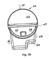
- FIG. 3 b is a plan view similar to that of FIG. 3 a , except with a cover on the tank and with a lid of the cover in an open condition.
- FIG. 4 a is a first side section view along line 4 a — 4 a of FIG. 3 .
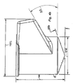
- FIG. 4 b is a side view corresponding to FIG. 4 a.
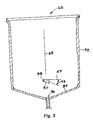
- FIG. 5 is a second side section view along line 5 — 5 of FIG. 3 a.
- FIG. 6 a is a fragmentary schematic representation of various flow rate ranges present in the lower portion of the mixing tank of the present invention.
- FIG. 6 b is a key showing the hatching for the various flow rate ranges of FIG. 6 a.
- FIG. 7 a is a schematic representation of various flow rate ranges present in the mixing tank of the present invention, particularly illustrating the flow rate ranges in the upper portion of the tank.
- FIG. 7 b is a key showing the hatching for the various flow rate ranges of FIG. 7 a.
- FIG. 7 c is a perspective view from above showing a simplified view of a generally vertically oriented rotational flow pattern.
- FIG. 7 d is a top view showing the pattern of FIG. 7 c , along with a generally horizontally oriented rotational flow pattern.
- FIG. 7 e is a view similar to that of FIG. 7 c , except with the vertical and horizontal flow patterns shown as shaded solids using a computer modeling program to illustrate further features of the present invention.
- FIG. 7 f is a view similar to that of FIG. 4 b , except showing the vertical and horizontal flow patterns in a side elevation view.
- FIG. 8 is a simplified diagram showing an air aspirated dry chemical delivery system useful in the practice of the present invention.
- FIG. 9 is a detailed section view of a venturi eductor useful in the practice of the present invention.
- FIG. 10 a is a perspective view of a group of containers located on a pallet for shipping dry chemicals for use in the practice of the present invention.
- FIG. 10 b is a top plan view of the containers and pallet of FIG. 10 a.
- FIG. 10 c is a side view of the containers and pallet of FIG. 10 a.
- FIG. 10 d is a view of three containers from FIG. 10 a in a nested configuration and with a lid for one container.
- FIG. 11 is a perspective view from below showing an arrangement of load cells useful in the practice of the present invention.
- System 20 includes a mixing tank 22 and a pump 24 , connected to the mixing tank via a tank drain line 26 and a fluid return line 28 .
- mixing tank 22 is preferably charged with a predetermined amount of deionized, AAMI (Association for the Advancement of Medical Instrumentation, 1110 N. Glebe Road, Suite 220, Arlington, Va. 22201-4795) standard hemodialysis quality water to make up a known quantity of dialysis solution by adding dry chemicals appropriate to form the dialysis solution in the concentration desired.
- AAMI Association for the Advancement of Medical Instrumentation, 1110 N. Glebe Road, Suite 220, Arlington, Va. 22201-4795
- standard hemodialysis quality water to make up a known quantity of dialysis solution by adding dry chemicals appropriate to form the dialysis solution in the concentration desired.
- the mixing tank 22 of the present invention is sized to have a height limited to about average human waist height to reduce the effort needed to manually transfer the chemicals into the tank.
- dry chemicals may be added to the water using an air eductor system which is described infra.
- the dry chemicals are extracted from one or more containers (not shown in FIG. 1, but preferably located adjacent the mixing tank). During and after the dry chemicals are added, the fluid (thus including some and eventually all of the quantity of added chemicals) is recirculated using the pump 24 and fluid lines 26 and 28 to achieve an evenly distributed, fully solubilized hemodialysis solution.
- Tank 22 has an upright mixing chamber 30 having a right circular cylinder sidewall 32 extending up from a bottom wall 34 , which is preferably conical.
- cylinder means a volume defined by a closed plane curve forming a base with a closed plane curve (which is preferably, but not necessarily identical) parallel to it.
- Cylinder also means the surface defined by a generator, which is a line segment from a point on one curve to a corresponding point on the other curve.
- cone and conical refer to a volume defined by a closed plane curve forming the base and a point (the vertex) outside the plane.
- a drain connection 36 is formed in the lowermost region of the bottom wall (which preferably is at the vertex of the bottom wall 34 when the wall is conical).
- the drain connection is fluidly connected to tank drain line 26 .
- a fluid supply nozzle 38 projects through cylinder sidewall 32 generally along a diameter 44 of the circular cross section of the tank 22 and has a fluid outlet 40 directed at a horizontal angle 42 away from the diameter 44 of the cylinder sidewall 32 , as may be seen in FIG. 3 a .
- Both the drain connection 36 and the fluid supply nozzle 38 preferably have a 1 inch inside diameter.
- fluid outlet 40 is directed at a vertical angle 48 with respect to a horizontal line 47 .
- Angle 42 is preferably 20 degrees and angle 48 is preferably 23.8 degrees. Each of angles 42 and 48 may be selected to be within the range of 10 to 60 degrees.
- the fluid supply nozzle preferably projects in from the inner surface of the cylindrical sidewall 32 a distance 46 of 3.74 inches.
- the length of the outlet 40 extending from the fluid supply nozzle is preferably 2.2 inches.
- the fluid supply nozzle is preferably positioned a distance 51 of 1.83 inches above the junction of the sidewall 32 and the bottom wall 34 .
- the nozzle 38 is positioned a distance 53 of 6.74 inches above the plane of the drain connection 36 .
- Nozzle 38 is located a distance 55 of 7.64 inches below the lower surface 54 as measured from the intersection of an asymptote 57 of the lower surface 54 and a projection 59 of the cylindrical wall 32 below the surface 54 .
- tank 22 preferably has an enlarged portion or cavity 52 in its upper region defined by a sloping, non-horizontal lower surface or ramp-like extension 54 , a pair of generally vertical side walls 56 , 58 , and a generally vertical and slightly angled stepped front wall or outer wall 60 .
- the ramp-like extension projects laterally out from a portion of the cylindrical side wall 32 a distance 61 of 13.57 inches.
- Outer wall 60 preferably is oriented at an angle 63 of 10 degrees.
- the ramp-like extension preferably has an angle 33 of 30 degrees (plus or minus 3 degrees) with respect to horizontal.
- angle 33 may be selected to be within the range of 10 to 85 degrees.
- the ramp-like extension may be curved in various ways, and desirably is shaped to minimize “dead spots” i.e., those regions which do not have as much flow as other regions of the mixing chamber.
- Extension side walls 56 and 58 are preferably spaced apart a distance close to or equal to the diameter 44 of tank 22 to provide an increased capacity for tank 22 while limiting the height and width of tank 22 .
- walls 56 and 58 preferably taper slightly towards each other as they extend away from the cylindrical portion of the tank.
- the width of tank 22 is preferably less than or equal to 32 inches to enable passage of tank 22 through a standard width door.
- the height 100 is preferably 32.5 inches from an upper edge to the drain connection 36 to enable the tank to be mounted with its upper edge no higher than 48 inches above the adjacent floor to reduce the height necessary to lift containers of dry chemical when preparing a dialysis solution.
- Providing enlarged portion or cavity 52 enables tank 22 to have a capacity of 110 gallons with a reduced height over that which would be necessary with a conventional simple cylindrical tank.
- Tank 22 has a length 102 of 43.33 inches and a width of 28.5 inches (not including the upper rim).
- the angle 106 of the cone of the bottom surface is preferably 20 degrees.
- Tank 22 is preferably formed of high density polyethylene, but may be formed of other materials, as desired.
- the mixing tank apparatus 22 of the present invention is thus seen to include a mixing chamber 23 having a generally vertical sidewall 32 extending upward from the bottom wall 34 .
- Sidewall 32 preferably circumscribes at least a portion of a cylinder to form a main well.
- the mixing chamber also has cavity 52 extending generally horizontally and projecting outward from the vertical sidewall 32 .
- the mixing tank 22 also includes drain connection 36 located at a lowermost portion of the bottom wall, and further includes the fluid supply nozzle 38 projecting into the mixing chamber, with the nozzle 38 directed at least partially toward the cavity 52 so that fluid is drawn from the mixing chamber by the drain connection 36 and is returned to the mixing chamber by the fluid supply nozzle 38 and the combination of the drain connection and fluid nozzle create a first rotational pattern and a second rotational pattern in the fluid, with the first pattern having a generally vertically-oriented vortex and the second pattern having a horizontally-oriented vortex in the mixing chamber (as will be described in more detail infra) to accelerate dissolving of the dry chemicals.
- a cover 62 shown in FIG. 3 b , has a “D” shaped lid 63 which provides a corresponding “D” shaped opening 64 for access to the mixing chamber 30 of tank 22 for adding dry chemicals.
- the lid 63 preferably remains closed over opening 64 in cover 62 when the dry chemicals are added using an eductor as described infra.
- the design of tank 22 provides a low vertical profile such that a person of average build will be able to more easily manually transfer the dry chemicals to the tank, by having a relatively low upper edge of the tank over which the dry chemicals must be lifted in the manual transfer operation, if that process is used.
- the tank height is 36 inches, allowing the upper edge to be no greater than 48 inches above an adjacent surface such as a floor on which the person delivering the chemicals would stand while manually transferring the chemicals to the tank.
- the low vertical profile is 35.5 inches from a top of the mixing tank to a lowermost portion of the bottom wall of the mixing tank.
- the tank design of the present invention also provides improved mixing by creating rapid and turbulent liquid flow at the bottom of the tank to prevent settling of chemical solids.
- the mixing fluid liquid and undissolved solids
- the irregular geometry of the tank also allows the accommodation of large volume preparations while maintaining waist high tank access to permit manual transfer of the solid chemicals to the tank.
- FIG. 6 a a computer model of the mixing taking place in the lower portion of tank 22 is illustrated in FIG. 6 a , with a key to the flow rate hatching in FIG. 6 b in units of feet/second.
- FIG. 6 a is a sectional view and that the hatched regions are generally toroidal in their three-dimensional shape. It is further to be noted that the transitions between hatched regions are not abrupt, but gradual, with the dashed boundary lines between hatched regions provided for simplicity of illustration.
- FIG. 6 a illustrates a generally concentric family of mixing velocities at one point in time, with variations occurring over time.
- FIG. 6 a illustrates a generally concentric family of mixing velocities at one point in time, with variations occurring over time.
- FIG. 6 a shows a central axis of rotation 65 generally aligned concentrically within region 66 (for that moment in time), with region 66 being understood to be the region having the lowest flow rate. Most importantly, the central axis of rotation 65 is not concentric with the cylindrical sidewall 32 of the tank 22 . It is to be further understood that while FIG. 6 a shows the central axis 65 as linear, it is actually typically curvilinear, and has random fluctuations both in its curvature and location, analogous to a naturally occurring tornado or cyclone. Such fluctuations are desirable in that they add to the mixing effect of the present invention.
- the locus of the central axis of rotation 65 of the lowest flow region 66 is eccentrically positioned and angularly offset from a central axis 68 of the cylinder side wall 32 .
- the improved results are due to the rapid flow rates at the bottom of the tank as well as the turbulence created as the circulating fluid collides with the irregular surfaces of the tank interior.
- the recirculation apparatus of the present invention also provides a horizontally oriented rotational flow pattern 108 in an upper portion of the tank 22 as shown in FIG. 7 a .
- the horizontally oriented mixing pattern has a generally L-shaped “central axis” with slight random “wave-like” or “snake-like” movement of both the shape and location of the “central axis” of the horizontal mixing pattern, all in an upper region of the tank.
- the mixing patterns are shown as discrete images in FIGS.
- FIG. 8 is a simplified block diagram illustrating the use of a venturi eductor 70 to draw dry chemicals from container 72 and deliver the dry chemicals to the mixing tank 22 .
- FIG. 9 is a section view of the venturi eductor 70 .
- a fluid which may be a gas such as compressed air, is delivered to inlet 74 .
- the fluid may be a liquid, such as the water from mixing tank 22 .
- the fluid indicated by arrows 76 enters an inlet flow path 78 for the chemicals through a plurality of angled apertures 80 .
- Eductor 70 creates a low pressure region at the material inlet 84 , entraining the dry chemicals as either air borne or liquid borne particulates indicated by arrows 82 , delivering the chemical particulate at material outlet 86 .
- An inlet hose 88 is preferably connected to material inlet 84 to pick up the dry chemical from container 72
- a delivery hose 90 is connected to material outlet 86 to deliver the chemicals to mixing tank 22 .
- a certain amount of dissolution may take place in the eductor and delivery hose when a liquid propelled system is used, but that it is contemplated that the majority of mixing will take place in the mixing chamber of the mixing tank, because the particulate will not remain long in the eductor or delivery hose.
- a jet pump (not shown) may be used in place of eductor 70 .
- containers 112 for shipping the dry chemicals can be seen, along with a cover 114 for one container.
- the containers are preferably tapered to permit stacking (as shown in FIG. 10 d ) when empty, to facilitate return and reuse by the shipper.
- Each shipping container has a plurality of recessed panels 115 to provide stiffening for the container.
- the dry chemicals may be carried within a polymer bag or liner (not shown) within an individual shipping container 112 . As may be seen in FIGS.
- each shipping container 112 has a maximum width 116 of 20 inches and a maximum length 118 of 16 inches such that an array of six containers 112 will have overall dimensions 122 , 124 of 48 and 40 inches, respectively, with a height 124 of 48 inches, so as to fit on a conventional shipping pallet 126 .
- Containers 112 are preferably formed of high density polyethylene but may be made of other materials, as desired.
- a single load cell or a plurality of load cells may be used to determine the weight of the water (initially) and (subsequently) the combined weight of chemicals and water in the mixing tank 22 .
- FIG. 11 shows an exploded view of suitable for this purpose.
- Each load cell 128 is preferably mounted in a recess 130 , engaging tank 22 via a stud 132 .
Abstract
Description
Claims (40)
Priority Applications (1)
| Application Number | Priority Date | Filing Date | Title |
|---|---|---|---|
| US10/279,527 US6830367B2 (en) | 2001-07-02 | 2002-10-24 | Dialysis solution system and mixing tank |
Applications Claiming Priority (2)
| Application Number | Priority Date | Filing Date | Title |
|---|---|---|---|
| US29144403 | 2001-07-02 | ||
| US10/279,527 US6830367B2 (en) | 2001-07-02 | 2002-10-24 | Dialysis solution system and mixing tank |
Related Parent Applications (1)
| Application Number | Title | Priority Date | Filing Date |
|---|---|---|---|
| US29144403 Continuation-In-Part | 2001-07-02 | 2001-07-02 |
Publications (2)
| Publication Number | Publication Date |
|---|---|
| US20030043688A1 US20030043688A1 (en) | 2003-03-06 |
| US6830367B2 true US6830367B2 (en) | 2004-12-14 |
Family
ID=22508423
Family Applications (1)
| Application Number | Title | Priority Date | Filing Date |
|---|---|---|---|
| US10/279,527 Expired - Fee Related US6830367B2 (en) | 2001-07-02 | 2002-10-24 | Dialysis solution system and mixing tank |
Country Status (1)
| Country | Link |
|---|---|
| US (1) | US6830367B2 (en) |
Cited By (7)
| Publication number | Priority date | Publication date | Assignee | Title |
|---|---|---|---|---|
| US20070059819A1 (en) * | 2005-09-12 | 2007-03-15 | Progressive Gardens, Llc Dba Progress Earth | Compost tea brewer |
| US20070263481A1 (en) * | 2006-05-11 | 2007-11-15 | Rineco Chemical Industries, Inc. | Method and device for agitation of tank-stored material |
| US20090187138A1 (en) * | 2008-01-18 | 2009-07-23 | Baxter International Inc. | Reusable effluent drain container for dialysis and other medical fluid therapies |
| US8540937B2 (en) | 2005-03-18 | 2013-09-24 | Ecolab Inc. | Formulating chemical solutions based on volumetric and weight based control measurements |
| US8602069B2 (en) | 2010-05-20 | 2013-12-10 | Ecolab Usa Inc. | Solid chemical product dilution control |
| US9700854B2 (en) | 2013-03-15 | 2017-07-11 | Ecolab Usa Inc. | Chemical dilution system |
| US11524270B2 (en) | 2018-04-27 | 2022-12-13 | Baxter International Inc. | Method of mixing a pharmaceutical solution and mixing system |
Families Citing this family (25)
| Publication number | Priority date | Publication date | Assignee | Title |
|---|---|---|---|---|
| US6830367B2 (en) * | 2001-07-02 | 2004-12-14 | Minntech Corporation | Dialysis solution system and mixing tank |
| US20040226959A1 (en) | 2003-05-12 | 2004-11-18 | Mehus Richard J. | Methods of dispensing |
| US7201290B2 (en) * | 2003-05-12 | 2007-04-10 | Ecolab Inc. | Method and apparatus for mass based dispensing |
| US6926239B1 (en) * | 2004-01-23 | 2005-08-09 | Dimaggio Edward J. | Mounting assembly for a waste discharge line of a medical treatment apparatus |
| EP1759170B2 (en) | 2004-06-23 | 2019-11-06 | Ecolab Inc. | Method for multiple dosage of liquid products, dosing appartus and dosing system |
| WO2006041541A1 (en) * | 2004-10-07 | 2006-04-20 | Christopher White | A mixing system |
| US20060127609A1 (en) * | 2004-12-14 | 2006-06-15 | Davies Max I | Fire retardant molded artificial stone |
| US7350963B2 (en) * | 2005-02-04 | 2008-04-01 | Hamilton Beach Brands, Inc. | Blender jar |
| US8277745B2 (en) * | 2007-05-02 | 2012-10-02 | Ecolab Inc. | Interchangeable load cell assemblies |
| US7694589B2 (en) * | 2007-12-12 | 2010-04-13 | Ecolab Inc. | Low and empty product detection using load cell and load cell bracket |
| WO2009128031A1 (en) * | 2008-04-14 | 2009-10-22 | Schlumberger Canada Limited | Container system |
| USRE48951E1 (en) | 2015-08-05 | 2022-03-01 | Ecolab Usa Inc. | Hand hygiene compliance monitoring |
| US9102509B2 (en) * | 2009-09-25 | 2015-08-11 | Ecolab Inc. | Make-up dispense in a mass based dispensing system |
| US9051163B2 (en) * | 2009-10-06 | 2015-06-09 | Ecolab Inc. | Automatic calibration of chemical product dispense systems |
| US8511512B2 (en) | 2010-01-07 | 2013-08-20 | Ecolab Usa Inc. | Impact load protection for mass-based product dispensers |
| US8944286B2 (en) | 2012-11-27 | 2015-02-03 | Ecolab Usa Inc. | Mass-based dispensing using optical displacement measurement |
| JP6153021B2 (en) * | 2013-06-05 | 2017-06-28 | パナソニックIpマネジメント株式会社 | Liquid preparation device |
| KR20180049193A (en) * | 2014-02-21 | 2018-05-10 | 라이프 테크놀로지스 코포레이션 | Systems, methods, and apparatuses for media rehydration |
| ES2622351T3 (en) * | 2014-10-15 | 2017-07-06 | Dunschat, Christoph | Dialysis concentrate manufacturing arrangement |
| BR112019018376B1 (en) | 2017-03-07 | 2024-02-20 | Ecolab Usa Inc | DEVICE, AND, DISPENSER SIGNALING MODULE |
| US10529219B2 (en) | 2017-11-10 | 2020-01-07 | Ecolab Usa Inc. | Hand hygiene compliance monitoring |
| DE102019101288A1 (en) * | 2018-01-22 | 2019-07-25 | Donaldson Company, Inc. | Diesel emission fluid tank with integrated misfill protection device |
| WO2020132525A1 (en) | 2018-12-20 | 2020-06-25 | Ecolab Usa Inc. | Adaptive route, bi-directional network communication |
| JP2023523795A (en) * | 2020-04-29 | 2023-06-07 | ケーエムダブリュ・インコーポレーテッド | Filter and manufacturing method thereof |
| US20210402359A1 (en) * | 2020-06-24 | 2021-12-30 | Fresenius Medical Care Holdings, Inc. | Turbulent flow mixing bag and related systems and methods |
Citations (44)
| Publication number | Priority date | Publication date | Assignee | Title |
|---|---|---|---|---|
| US626950A (en) * | 1899-06-13 | Island | ||
| US1580476A (en) * | 1923-07-28 | 1926-04-13 | Fassio Julius | Washing apparatus |
| US1991148A (en) * | 1930-08-11 | 1935-02-12 | Gephart Valentine | Mixing device |
| US2603460A (en) * | 1950-06-01 | 1952-07-15 | Infilco Inc | Dissolving and slurrying tank |
| US2795403A (en) * | 1954-10-28 | 1957-06-11 | William H Mead | Slurry mixing method and apparatus |
| US2906607A (en) * | 1956-06-22 | 1959-09-29 | Ajem Lab Inc | Powder dissolving apparatus |
| US2997373A (en) * | 1959-01-19 | 1961-08-22 | Barnard & Leas Mfg Company Inc | Dissolving apparatus |
| US3271304A (en) * | 1964-06-26 | 1966-09-06 | Pacific Flush Tank Co | Venturi aerator and aerating process for waste treatment |
| US3425669A (en) * | 1967-11-13 | 1969-02-04 | Preston G Gaddis | Dry chemical feeder method and apparatus |
| US3586294A (en) * | 1969-02-20 | 1971-06-22 | James J Strong | Method and apparatus for creating a suspension of fine particles in a liquid |
| US4325642A (en) * | 1979-09-11 | 1982-04-20 | Vysoka Skola Chemicko-Technologicka | Storage and homogenizing tank for kaolin suspensions |
| USD269148S (en) * | 1980-10-27 | 1983-05-31 | Capital Industries, Inc. | Beer keg cooler |
| USD270961S (en) * | 1981-11-13 | 1983-10-11 | Rubbermaid Commercial Products Inc. | Mop bucket |
| US4496244A (en) * | 1983-01-17 | 1985-01-29 | General Signal Corporation | Small volume mixing and recirculating apparatus |
| US4531652A (en) | 1984-06-25 | 1985-07-30 | Kabushiki Kaisha Kubota Seisakusho | Bucket for use in centrifugal separators |
| US4660988A (en) * | 1984-10-02 | 1987-04-28 | Toyoda Gosei Co., Ltd. | Stirring device for liquid material |
| US4664891A (en) | 1984-07-23 | 1987-05-12 | Renal Systems, Inc. | Dialysis solution preparation from prepackaged dry chemicals |
| EP0225237A1 (en) * | 1985-10-30 | 1987-06-10 | Jacques Dodier | Device for treating liquids by hydrokinetic injection |
| USD291022S (en) * | 1984-12-10 | 1987-07-28 | Erickson Richard D | Disposable shoe shine kit |
| US4734198A (en) | 1984-02-06 | 1988-03-29 | Minntech Corporation | Dialysis solution mixing system |
| US4812045A (en) * | 1987-08-20 | 1989-03-14 | Domtar Gypsum Inc. | Gypsum dissolution system |
| USD325344S (en) * | 1990-09-17 | 1992-04-14 | Scholle Corporation | Beverage container |
| USD328507S (en) * | 1987-03-05 | 1992-08-04 | Campbell Franklin R | Combination bucket and stool |
| US5253937A (en) * | 1992-06-29 | 1993-10-19 | Nalco Chemical Company | Method and apparatus for dispersing or dissolving particles of a pelletized material in a liquid |
| USD348130S (en) * | 1992-12-28 | 1994-06-21 | Rubbermaid Incorporated | Bucket |
| USD374321S (en) * | 1995-09-29 | 1996-10-01 | Rubbermaid Commercial Products Inc. | Mop bucket |
| US5609417A (en) * | 1994-11-28 | 1997-03-11 | Otte; Doyle D. | Apparatus for mixing and circulating chemicals and fluids |
| US5690821A (en) | 1995-02-13 | 1997-11-25 | Aksys, Ltd. | Apparatus for supplying a batch of chemicals to a dialysate tank |
| USD395531S (en) * | 1997-01-27 | 1998-06-23 | Rubbermaid Commerical Products Inc. | Mop bucket |
| US5769536A (en) * | 1996-11-08 | 1998-06-23 | Kotylak; Clayton | Mixing container for dissolving dry chemicals in water |
| US5782376A (en) * | 1995-05-25 | 1998-07-21 | General Mills, Inc. | Thermoformed plastic containers and their method of manufacture |
| USD405931S (en) * | 1996-11-15 | 1999-02-16 | South Australian Malting Company Pty Limited | Beer keg |
| USD422770S (en) * | 1999-07-02 | 2000-04-11 | Schmitt Anthony L | Combined container and pallet |
| USD422609S (en) * | 1999-02-25 | 2000-04-11 | 3D Systems, Inc. | Container for material loading |
| US6065860A (en) * | 1993-07-23 | 2000-05-23 | Fuchsbichler; Kevin Johan | Recirculation apparatus and method for dissolving particulate solids in a liquid |
| USD426044S (en) * | 1998-06-08 | 2000-05-30 | Walbro Corporation | Drum |
| US6109778A (en) * | 1997-09-22 | 2000-08-29 | United States Filter Corporation | Apparatus for homogeneous mixing of a solution with tangential jet outlets |
| US6186657B1 (en) * | 1996-05-31 | 2001-02-13 | Kevin Johan Fuchsbichler | Apparatus and method for mixing particulate solids or gels in a liquid |
| US6210803B1 (en) | 1997-04-24 | 2001-04-03 | Fresenius Medical Care Deutschland Gmbh | Method for the production of a granulate for hemodialysis |
| US6251437B1 (en) | 1999-07-13 | 2001-06-26 | Minntech Corporation | Liquid/powder acid concentrate for dialysate and a method of making the same |
| US6395180B2 (en) | 1998-09-18 | 2002-05-28 | Rockwell Medical Technologies, Inc. | Method and apparatus for preparing liquid dialysate |
| US20020105855A1 (en) | 2001-01-24 | 2002-08-08 | Richard Behnke | Storage/treatment tank mixing system |
| US20030043688A1 (en) * | 2001-07-02 | 2003-03-06 | Peterson Roger A. | Dialysis solution system and mixing tank |
| US6592246B2 (en) * | 2000-08-28 | 2003-07-15 | Csir | Method and installation for forming and maintaining a slurry |
-
2002
- 2002-10-24 US US10/279,527 patent/US6830367B2/en not_active Expired - Fee Related
Patent Citations (44)
| Publication number | Priority date | Publication date | Assignee | Title |
|---|---|---|---|---|
| US626950A (en) * | 1899-06-13 | Island | ||
| US1580476A (en) * | 1923-07-28 | 1926-04-13 | Fassio Julius | Washing apparatus |
| US1991148A (en) * | 1930-08-11 | 1935-02-12 | Gephart Valentine | Mixing device |
| US2603460A (en) * | 1950-06-01 | 1952-07-15 | Infilco Inc | Dissolving and slurrying tank |
| US2795403A (en) * | 1954-10-28 | 1957-06-11 | William H Mead | Slurry mixing method and apparatus |
| US2906607A (en) * | 1956-06-22 | 1959-09-29 | Ajem Lab Inc | Powder dissolving apparatus |
| US2997373A (en) * | 1959-01-19 | 1961-08-22 | Barnard & Leas Mfg Company Inc | Dissolving apparatus |
| US3271304A (en) * | 1964-06-26 | 1966-09-06 | Pacific Flush Tank Co | Venturi aerator and aerating process for waste treatment |
| US3425669A (en) * | 1967-11-13 | 1969-02-04 | Preston G Gaddis | Dry chemical feeder method and apparatus |
| US3586294A (en) * | 1969-02-20 | 1971-06-22 | James J Strong | Method and apparatus for creating a suspension of fine particles in a liquid |
| US4325642A (en) * | 1979-09-11 | 1982-04-20 | Vysoka Skola Chemicko-Technologicka | Storage and homogenizing tank for kaolin suspensions |
| USD269148S (en) * | 1980-10-27 | 1983-05-31 | Capital Industries, Inc. | Beer keg cooler |
| USD270961S (en) * | 1981-11-13 | 1983-10-11 | Rubbermaid Commercial Products Inc. | Mop bucket |
| US4496244A (en) * | 1983-01-17 | 1985-01-29 | General Signal Corporation | Small volume mixing and recirculating apparatus |
| US4734198A (en) | 1984-02-06 | 1988-03-29 | Minntech Corporation | Dialysis solution mixing system |
| US4531652A (en) | 1984-06-25 | 1985-07-30 | Kabushiki Kaisha Kubota Seisakusho | Bucket for use in centrifugal separators |
| US4664891A (en) | 1984-07-23 | 1987-05-12 | Renal Systems, Inc. | Dialysis solution preparation from prepackaged dry chemicals |
| US4660988A (en) * | 1984-10-02 | 1987-04-28 | Toyoda Gosei Co., Ltd. | Stirring device for liquid material |
| USD291022S (en) * | 1984-12-10 | 1987-07-28 | Erickson Richard D | Disposable shoe shine kit |
| EP0225237A1 (en) * | 1985-10-30 | 1987-06-10 | Jacques Dodier | Device for treating liquids by hydrokinetic injection |
| USD328507S (en) * | 1987-03-05 | 1992-08-04 | Campbell Franklin R | Combination bucket and stool |
| US4812045A (en) * | 1987-08-20 | 1989-03-14 | Domtar Gypsum Inc. | Gypsum dissolution system |
| USD325344S (en) * | 1990-09-17 | 1992-04-14 | Scholle Corporation | Beverage container |
| US5253937A (en) * | 1992-06-29 | 1993-10-19 | Nalco Chemical Company | Method and apparatus for dispersing or dissolving particles of a pelletized material in a liquid |
| USD348130S (en) * | 1992-12-28 | 1994-06-21 | Rubbermaid Incorporated | Bucket |
| US6065860A (en) * | 1993-07-23 | 2000-05-23 | Fuchsbichler; Kevin Johan | Recirculation apparatus and method for dissolving particulate solids in a liquid |
| US5609417A (en) * | 1994-11-28 | 1997-03-11 | Otte; Doyle D. | Apparatus for mixing and circulating chemicals and fluids |
| US5690821A (en) | 1995-02-13 | 1997-11-25 | Aksys, Ltd. | Apparatus for supplying a batch of chemicals to a dialysate tank |
| US5782376A (en) * | 1995-05-25 | 1998-07-21 | General Mills, Inc. | Thermoformed plastic containers and their method of manufacture |
| USD374321S (en) * | 1995-09-29 | 1996-10-01 | Rubbermaid Commercial Products Inc. | Mop bucket |
| US6186657B1 (en) * | 1996-05-31 | 2001-02-13 | Kevin Johan Fuchsbichler | Apparatus and method for mixing particulate solids or gels in a liquid |
| US5769536A (en) * | 1996-11-08 | 1998-06-23 | Kotylak; Clayton | Mixing container for dissolving dry chemicals in water |
| USD405931S (en) * | 1996-11-15 | 1999-02-16 | South Australian Malting Company Pty Limited | Beer keg |
| USD395531S (en) * | 1997-01-27 | 1998-06-23 | Rubbermaid Commerical Products Inc. | Mop bucket |
| US6210803B1 (en) | 1997-04-24 | 2001-04-03 | Fresenius Medical Care Deutschland Gmbh | Method for the production of a granulate for hemodialysis |
| US6109778A (en) * | 1997-09-22 | 2000-08-29 | United States Filter Corporation | Apparatus for homogeneous mixing of a solution with tangential jet outlets |
| USD426044S (en) * | 1998-06-08 | 2000-05-30 | Walbro Corporation | Drum |
| US6395180B2 (en) | 1998-09-18 | 2002-05-28 | Rockwell Medical Technologies, Inc. | Method and apparatus for preparing liquid dialysate |
| USD422609S (en) * | 1999-02-25 | 2000-04-11 | 3D Systems, Inc. | Container for material loading |
| USD422770S (en) * | 1999-07-02 | 2000-04-11 | Schmitt Anthony L | Combined container and pallet |
| US6251437B1 (en) | 1999-07-13 | 2001-06-26 | Minntech Corporation | Liquid/powder acid concentrate for dialysate and a method of making the same |
| US6592246B2 (en) * | 2000-08-28 | 2003-07-15 | Csir | Method and installation for forming and maintaining a slurry |
| US20020105855A1 (en) | 2001-01-24 | 2002-08-08 | Richard Behnke | Storage/treatment tank mixing system |
| US20030043688A1 (en) * | 2001-07-02 | 2003-03-06 | Peterson Roger A. | Dialysis solution system and mixing tank |
Cited By (9)
| Publication number | Priority date | Publication date | Assignee | Title |
|---|---|---|---|---|
| US8540937B2 (en) | 2005-03-18 | 2013-09-24 | Ecolab Inc. | Formulating chemical solutions based on volumetric and weight based control measurements |
| US20070059819A1 (en) * | 2005-09-12 | 2007-03-15 | Progressive Gardens, Llc Dba Progress Earth | Compost tea brewer |
| US20070263481A1 (en) * | 2006-05-11 | 2007-11-15 | Rineco Chemical Industries, Inc. | Method and device for agitation of tank-stored material |
| US8328409B2 (en) | 2006-05-11 | 2012-12-11 | Rineco Chemical Industries, Inc. | Method and device for agitation of tank-stored material |
| US20090187138A1 (en) * | 2008-01-18 | 2009-07-23 | Baxter International Inc. | Reusable effluent drain container for dialysis and other medical fluid therapies |
| US8545425B2 (en) | 2008-01-18 | 2013-10-01 | Baxter International | Reusable effluent drain container for dialysis and other medical fluid therapies |
| US8602069B2 (en) | 2010-05-20 | 2013-12-10 | Ecolab Usa Inc. | Solid chemical product dilution control |
| US9700854B2 (en) | 2013-03-15 | 2017-07-11 | Ecolab Usa Inc. | Chemical dilution system |
| US11524270B2 (en) | 2018-04-27 | 2022-12-13 | Baxter International Inc. | Method of mixing a pharmaceutical solution and mixing system |
Also Published As
| Publication number | Publication date |
|---|---|
| US20030043688A1 (en) | 2003-03-06 |
Similar Documents
| Publication | Publication Date | Title |
|---|---|---|
| US6830367B2 (en) | Dialysis solution system and mixing tank | |
| NZ529222A (en) | Apparatus and method for wetting powder | |
| CN110038476A (en) | A kind of jet stream-stirring manifold type powdery flocculation medicament quantifies dispersion mixing system | |
| KR101849854B1 (en) | Quantitative supplier for agricultural chemicals | |
| CN101454070B (en) | Gas dissolving apparatus | |
| US20230110920A1 (en) | Powder Hydration Systems with Mixing Apparatus and Methods Of Use | |
| US20040156262A1 (en) | Self-mixing tank | |
| US5899561A (en) | Method for making a product from separate bulk sources of supply of a liquid carrier and an additive | |
| CN207958333U (en) | Agitation Tank | |
| CN219506269U (en) | Buffer tank for liquid medicine filling system | |
| CN207958332U (en) | Powder material throwing device and tank body containing described device | |
| CN219546737U (en) | Medicine adding device | |
| CN215196740U (en) | Intelligent many feed bodies blendor | |
| EP0291209A2 (en) | Mixing and dispersing apparatus | |
| CN216038984U (en) | Sewage treatment equipment | |
| CN213863219U (en) | Liquid storage tank | |
| CN210814900U (en) | Medicine mixes homogenizes device | |
| CN216983530U (en) | Powder conveyor and liquid feed preparation system | |
| CN214636091U (en) | Lime liquid configuration system | |
| CN217140197U (en) | Dissolving and filtering device for dry powder retention and filter aid | |
| CN210063709U (en) | Active surface agent strorage device | |
| CN220741774U (en) | Waste plastic particle stirring assembly | |
| CN215472326U (en) | Plastic granules homogenization feed bin | |
| CN213853961U (en) | Full-automatic high-speed mixer | |
| JPH0742498Y2 (en) | Drug dissolving device |
Legal Events
| Date | Code | Title | Description |
|---|---|---|---|
| AS | Assignment |
Owner name: MINNTECH CORPORATION, MINNESOTA Free format text: ASSIGNMENT OF ASSIGNORS INTEREST;ASSIGNORS:PETERSON, ROGER A.;MATTA, JOHN J.;WALTER, BERT;REEL/FRAME:013424/0464;SIGNING DATES FROM 20021023 TO 20021024 |
|
| CC | Certificate of correction | ||
| AS | Assignment |
Owner name: BANK OF AMERICA, N.A., AS ADMINISTRATIVE AGENT, MA Free format text: NOTICE OF GRANT OF SECURITY INTEREST;ASSIGNOR:MINNTECH CORPORATION;REEL/FRAME:016883/0590 Effective date: 20050801 |
|
| FPAY | Fee payment |
Year of fee payment: 4 |
|
| AS | Assignment |
Owner name: BANK OF AMERICA, N.A., AS ADMINISTRATIVE AGENT, MA Free format text: NOTICE OF GRANT OF SECURITY INTEREST IN PATENTS;ASSIGNOR:MINNTECH CORPORATION;REEL/FRAME:026693/0692 Effective date: 20110801 |
|
| REMI | Maintenance fee reminder mailed | ||
| LAPS | Lapse for failure to pay maintenance fees | ||
| STCH | Information on status: patent discontinuation |
Free format text: PATENT EXPIRED DUE TO NONPAYMENT OF MAINTENANCE FEES UNDER 37 CFR 1.362 |
|
| FP | Lapsed due to failure to pay maintenance fee |
Effective date: 20121214 |
|
| AS | Assignment |
Owner name: MINNTECH CORPORATION, NEW JERSEY Free format text: TERMINATION AND RELEASE OF SECURITY INTEREST IN PATENTS;ASSIGNOR:BANK OF AMERICA, N.A., AS ADMINISTRATIVE AGENT;REEL/FRAME:056470/0021 Effective date: 20210602 Owner name: MINNTECH CORPORATION, NEW JERSEY Free format text: TERMINATION AND RELEASE OF SECURITY INTEREST IN PATENTS;ASSIGNOR:BANK OF AMERICA, N.A., AS ADMINISTRATIVE AGENT;REEL/FRAME:056593/0336 Effective date: 20210602 |