US6822417B2 - Synchronous reluctance motor control device - Google Patents
Synchronous reluctance motor control device Download PDFInfo
- Publication number
- US6822417B2 US6822417B2 US10/481,059 US48105904A US6822417B2 US 6822417 B2 US6822417 B2 US 6822417B2 US 48105904 A US48105904 A US 48105904A US 6822417 B2 US6822417 B2 US 6822417B2
- Authority
- US
- United States
- Prior art keywords
- motor
- voltage
- synchronous reluctance
- torque
- unit
- Prior art date
- Legal status (The legal status is an assumption and is not a legal conclusion. Google has not performed a legal analysis and makes no representation as to the accuracy of the status listed.)
- Expired - Fee Related
Links
Images


Classifications
-
- H—ELECTRICITY
- H02—GENERATION; CONVERSION OR DISTRIBUTION OF ELECTRIC POWER
- H02P—CONTROL OR REGULATION OF ELECTRIC MOTORS, ELECTRIC GENERATORS OR DYNAMO-ELECTRIC CONVERTERS; CONTROLLING TRANSFORMERS, REACTORS OR CHOKE COILS
- H02P25/00—Arrangements or methods for the control of AC motors characterised by the kind of AC motor or by structural details
- H02P25/02—Arrangements or methods for the control of AC motors characterised by the kind of AC motor or by structural details characterised by the kind of motor
- H02P25/08—Reluctance motors
- H02P25/092—Converters specially adapted for controlling reluctance motors
-
- H—ELECTRICITY
- H02—GENERATION; CONVERSION OR DISTRIBUTION OF ELECTRIC POWER
- H02P—CONTROL OR REGULATION OF ELECTRIC MOTORS, ELECTRIC GENERATORS OR DYNAMO-ELECTRIC CONVERTERS; CONTROLLING TRANSFORMERS, REACTORS OR CHOKE COILS
- H02P25/00—Arrangements or methods for the control of AC motors characterised by the kind of AC motor or by structural details
- H02P25/02—Arrangements or methods for the control of AC motors characterised by the kind of AC motor or by structural details characterised by the kind of motor
- H02P25/08—Reluctance motors
- H02P25/086—Commutation
- H02P25/089—Sensorless control
Definitions
- the present invention relates to a control apparatus of a synchronous reluctance motor, and more particularly to a control apparatus for driving the motor with estimation of the angle of the rotor without using position sensor.
- a conventional control apparatus of a synchronous reluctance motor is designed to obtain the angle information of a rotor by using a position sensor such as Hall element, resolver or optical encoder. Accordingly, the cost is increased by the portion of the position sensor, and the size of the synchronous reluctance motor is also increased.
- a control apparatus of the synchronous reluctance motor for realizing low cost and small size by omitting position sensors generally, a control apparatus of the synchronous reluctance motor as shown in FIG. 23 has been known.
- a main circuit includes an alternating-current power source 1 , an AC/DC converter 2 for converting an alternating-current power into a direct-current power, a DC/AC converter 3 for converting a direct-current power into an alternating-current power, and a synchronous reluctance motor 5 driving with the alternating-current power converted by the DC/AC converter 3 .
- a control circuit includes current detectors 11 a and 11 b and a motor current detector 12 for detecting the motor current, a position and speed estimation unit 13 for estimating the position and speed of the synchronous reluctance motor, a speed control unit 14 for determining a current command so as to eliminate the speed error between the speed command given from outside and the estimated speed obtained from the position and speed estimation unit 13 , a conduction phase distribution unit 15 for distributing the current command obtained from the speed control unit 14 into a torque current component and a field current component, a current control unit 17 for determining the voltage command so as to eliminate the current error of the torque current command and field current command, and the detected motor current, and a conduction distribution unit 18 for distributing the conduction signal into driving elements in the synchronous reluctance motor 5 .
- FIG. 24 is a sectional view showing a structure of a general synchronous reluctance motor 5 .
- the synchronous reluctance motor 5 is composed of a rotor 8 and a stator 6 .
- the position and speed estimation unit 13 determines the magnetic flux by using the information of the motor current command and voltage command. Next, an ⁇ - ⁇ magnetic flux angle showing the angle based on the stationary coordinates of this magnetic flux is determined. Further, a d-q axis coordinate phase indicating the phase of this magnetic flux corresponding to the rotational coordinates is set. The d-q axis coordinate phase is subtracted from the ⁇ - ⁇ axis coordinate angle to obtain an estimated angle. On the basis of this estimated angle, the synchronous reluctance motor 5 is controlled.
- the angle is estimated in two methods of low speed angle estimation and high speed angle estimation, and in the boundary of low speed region and high speed region, the angles estimated by two methods are synthesized by gradually changing the rate of the estimated angles to generate an estimated angle. In the low speed region, a current pulse is applied and the angle is obtained from the voltage response.
- the synchronous reluctance motor of driving system without using position sensor disclosed in Japanese Laid-open Patent No. 2001-197774 has low pass filter means for applying a low pass function to the voltage command, and weakens the low pass function when the rotor speed increases to eliminate effects of voltage pulse in the boundary region of low and high speed regions and change over the angle estimating methods stably, realizing the control of synchronous reluctance motor free from time delay in high speed region.
- the invention is intended to solve these problems of the prior art, and it is hence an object of the invention to present a control apparatus of the synchronous reluctance motor building up a robust control structure withstanding voltage saturation and steep load fluctuations.
- the motor control apparatus is an apparatus for controlling a synchronous reluctance motor by using a reluctance torque caused by at least a change in inductance of the stator winding and a motor current.
- a current detector detects the motor current flowing in the stator winding of the synchronous motor.
- a position and speed estimation unit estimates an induced voltage of the synchronous reluctance motor from the detected value by the current detector and a voltage command which is a command to a voltage to be applied to the stator winding of the synchronous reluctance motor, and estimated rotor position and rotating speed of the synchronous reluctance motor on the basis of the estimated induced voltage.
- a speed control unit determines a current command which is a command to a current to be supplied to the stator winding of the synchronous reluctance motor so as to eliminate the error of the estimated rotating speed by the position and speed estimation unit and a target value of the rotating speed given from outside.
- a distribution unit distributes the current command from the speed control unit into a torque current command which is a torque current component of the current command and a field current command which is a field current component of the current command, on the basis of a predetermined current phase angle of the synchronous reluctance motor.
- a torque current correction unit corrects the torque current command on the basis of the torque current command from the distribution unit and the estimated rotating speed from the position and speed estimation unit, so that a load torque generated by a load element of the synchronous reluctance motor coincides with the output torque of the synchronous reluctance motor.
- a current control unit generates a voltage command so as to eliminate the error between the corrected torque current command from the torque current correction unit and the detected motor current from the current detector, and the error between the field current command from the distribution unit and the detected motor current obtained from the current detector.
- a conduction distribution unit distributes conduction signals into driving elements in the synchronous reluctance motor on the basis of the voltage command.
- the control apparatus of the invention controls so that the load torque generated by the load element of the synchronous reluctance motor may always coincide with the output torque of the synchronous reluctance motor.
- FIG. 1 is a diagram showing an example of an entire configuration of a control apparatus of a synchronous reluctance motor (SRM) according to the invention.
- SRM synchronous reluctance motor
- FIG. 2 is an explanatory diagram of an example of a coordinate in position and speed estimation.
- FIG. 3 is a sectional view of one example of an permanent magnet assistance type synchronous reluctance motor according to the invention.
- FIG. 4 is a sectional view of the other example of an permanent magnet assistance type synchronous reluctance motor according to the invention.
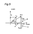
- FIG. 5 is a diagram showing an example of magnetic flux vector of an permanent magnet assistance type synchronous reluctance motor according to the invention.
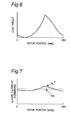
- FIG. 6 is a diagram showing a load torque characteristic of a general rotary compressor.
- FIG. 7 is a diagram showing an example of an output signal of a torque current correction unit in the control apparatus of SRM according to the invention.
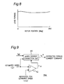
- FIG. 8 is a diagram showing a load torque characteristic of a general scroll compressor.
- FIG. 9 is a block diagram showing one structural example of the torque current correction unit in the control apparatus of SRM according to the invention.
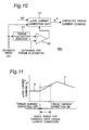
- FIG. 10 is a block diagram showing the other structural example of the torque current correction unit in the control apparatus of SRM according to the invention.
- FIG. 11 is a diagram showing a changeover mode of a torque current command at on/off changeover timing of torque current correction operation.
- FIG. 12 is a block diagram showing an example of a configuration of the speed control unit in the control apparatus of SRM according to the invention.
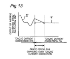
- FIG. 13 is a diagram showing a changeover mode of output of the average estimated speed unit in the control apparatus of SRM according to the invention.
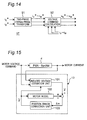
- FIG. 14 is a block diagram showing an example of a configuration of the current control unit in the control apparatus of SRM according to the invention.
- FIG. 15 is a block diagram showing an example of a configuration of the position and speed estimation unit in the control apparatus of SRM according to the invention.
- FIG. 16 is a block diagram showing an example of a configuration of the induced voltage estimation unit in the control apparatus of SRM according to the invention.
- FIG. 17 is a block diagram showing an example of a configuration the motor constant compensation unit in the control apparatus of SRM according to the invention.
- FIG. 18 is a block diagram showing other example of a configuration of the motor constant compensation unit in the control apparatus of SRM according to the invention.
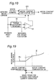
- FIG. 19 is a diagram showing a changeover mode of an output of the motor constant compensation unit at on/off changeover timing of motor constant compensation operation.
- FIG. 20 is a diagram showing the other example of entire configuration of the control apparatus of the synchronous reluctance motor according to the invention.
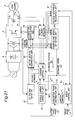
- FIG. 21 is a diagram showing still other example of entire configuration of the control apparatus of the synchronous reluctance motor according to the invention.
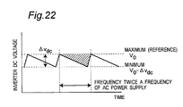
- FIG. 22 is a diagram explaining ripple components of an inverter direct-current voltage.
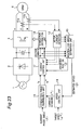
- FIG. 23 is a block diagram of a conventional control apparatus of synchronous reluctance motor.
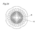
- FIG. 24 is a diagram showing a example of configuration of a conventional synchronous reluctance motor.
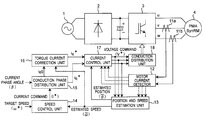
- FIG. 1 is a system block diagram showing an embodiment of a control apparatus of a synchronous reluctance motor according to the invention.
- An example explained below is a case of sinusoidal drive of an permanent magnet assistance type synchronous reluctance motor by 180-degree conduction without using position sensor.
- a main circuit includes an alternating-current power source 1 , an AC/DC converter 2 for converting an alternating-current power into a direct-current power, a DC/AC converter 3 for converting a direct-current power into an alternating-current power, and an permanent magnet assistance type synchronous reluctance motor 4 driving with the alternating-current power converted by the DC/AC converter 3 .
- a control circuit includes current detectors 11 a , 11 b and motor current detector 12 for detecting the motor current, a position and speed estimation unit 13 for estimating the position and speed of the permanent magnet assistance type synchronous reluctance motor, a speed control unit 14 for determining the current command so as to eliminate the speed error between the speed command given from outside and the estimated speed obtained from the position and speed estimation unit 13 , a conduction phase distribution unit 15 for distributing the current command obtained from the speed control unit 14 into a torque current component and a field current component, a torque current correction unit 16 for correcting the torque current command, a current control unit 17 for determining the voltage command so as to eliminate the current error between the corrected torque current command or field current command and detected motor current, and a conduction distribution unit 18 for distributing the conduction signal into driving elements in the permanent magnet assistance type synchronous reluctance motor 4 .
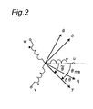
- FIG. 2 is a diagram of definition of axes of coordinates in position and speed estimation.
- the motor parameters are converted from three phases of u, v and w to two phases of d and q to be in DC status.
- the converting method from three phases to two phases is well known and thus is not explained here.
- ⁇ me is actual rotor position (phase difference from q-axis based on u-phase)
- ⁇ ⁇ is an estimated position (phase difference from y-axis of u-phase).
- Position error ⁇ is expressed as follows.
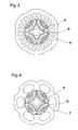
- FIG. 3 and FIG. 4 show examples of structure of permanent magnet assistant type synchronous reluctance motor 4 .
- the synchronous reluctance motor shown in FIG. 3 includes a distributed winding stator 6 and a rotor 8 having a permanent magnet 9 .
- the synchronous reluctance motor shown in FIG. 4 includes a concentrated winding stator 7 and a rotor 8 having a permanent magnet 9 .
- the permanent magnet 9 is preferred to have a magnetic quantity of a minimum limit only necessary for canceling the brake torque at a rated load of the synchronous reluctance motor. As a result, not only the motor efficiency at a rated load is improved, but also the cost increase due to the permanent magnet is kept to a minimum.
- FIG. 5 An example of the magnetic flux vector of the permanent magnet assistant type synchronous reluctance motor 4 is shown in FIG. 5 .
- the vector A is a magnetic flux component generating a positive torque
- a magnetic flux component (vector C) of assistant magnet acts to cancel a magnetic flux component (vector B) for generating a brake torque (negative torque).
- the generated torque is defined in formula (1).
- n p is the number of pole pairs
- L d and L q are d-axis and q-axis inductances, respectively
- ⁇ 0 is the number of flux interlinkages by the permanent magnet
- i d and i q are d-axis and q-axis current respectively.
- the speed control unit 14 determines the current command I* in the following formula, by using rotating speed command ⁇ * given from outside and estimated rotating speed ⁇ 18 .
- I * ( K P1 + K I1 p ) ⁇ ( ⁇ * - ⁇ ⁇ ) ( 2 )
- K p1 , K I1 are gains of the PI compensator, and p is a differential operator.
- the conduction phase distribution unit 15 distributes the current command I* into d-axis current i d * and q-axis current i q0 in the following formula, by using the current command I* and predetermined current phase angle ⁇ .
- the torque current correction unit 16 calculates q-axis current command i q * in the following formula, by using the estimated rotating speed ⁇ ⁇ and q-axis current i q0 .
- i q * i q0 + ( K P2 + K 12 P ) ⁇ ( ⁇ ⁇ ⁇ [ nT s ] - ⁇ ⁇ ⁇ [ ( n - 1 ) ⁇ T s ] ) ( 4 )
- a discrete time system is taken for operation by a microcomputer, in which nT s is a present sampling time, and (n ⁇ 1)T s is a sampling time one cycle before the present sampling time. Further, K p2 , K I2 are gains of the PI compensator.
- the torque current correction unit 16 obtains the q-axis current command i q * by using the formula above, so that the load torque generated by the load element of the permanent magnet assistant type synchronous reluctance motor may always coincide with the output torque of the permanent magnet assistant type synchronous reluctance motor.
- the current control unit 17 calculates voltage commands of three phases v u *, v v * and v W * in the following formula, by using the motor current detected values i u , i v and i w , and d-q axis current commands i d * and i q *.
- motor current detected values i u , i v and i w are converted into gamma-delta axis current detected values i ⁇ , i ⁇ .
- [ i ⁇ i ⁇ ] 2 3 ⁇ [ cos ⁇ ⁇ ⁇ ⁇ cos ⁇ ( ⁇ ⁇ - 2 ⁇ ⁇ / 3 ) cos ⁇ ( ⁇ ⁇ + 2 ⁇ ⁇ / 3 ) sin ⁇ ⁇ ⁇ ⁇ sin ⁇ ( ⁇ ⁇ - 2 ⁇ ⁇ / 3 ) sin ⁇ ( ⁇ ⁇ + 2 ⁇ ⁇ / 3 ) ] ⁇ [ i u i v i w ] ( 5 )
- K p3 , K I3 , and K p4 , K I4 are gains of the PI compensator.
- the position and speed estimation unit 13 estimates the position and speed in the following method, by using the voltage commands of three phases v u *, v v * and v w * and motor current detected values i u , i v and i w .
- phase voltage, phase current, and induced voltage v uvw , i uvw , e uvw are three-dimensional vectors, and the stator winding resistance and inductances R and L are expressed in a matrix with three columns and three rows, respectively.
- Induced voltages e u , e v and e w can be expressed in formula (10), by using the estimated rotating speed ⁇ ⁇ and induced voltage constant K E .
- e w ⁇ ⁇ ⁇ K E ⁇ sin ⁇ ( ⁇ ⁇ + 2 ⁇ ⁇ / 3 ) ( 10 )
- ⁇ ⁇ u , ⁇ ⁇ v and ⁇ ⁇ w are expressed in formula (12).
- ⁇ ⁇ u ⁇ ⁇ [ nT s ] sin - 1 ⁇ [ e u ⁇ ( ⁇ ⁇ + ⁇ 0 ) ⁇ K E ]
- ⁇ 0 is an infinitesimal term for prevention of zero division.
- the torque current command conforming to the load torque as shown in FIG. 7 is generated by the torque current correction unit.
- the output torque of the synchronous reluctance motor may always coincide with the load torque.
- the permanent magnet assistant type synchronous reluctance motor is driven by the sinusoidal operation of 180-degree conduction without using the position sensor.
- the permanent magnet is used in the rotor in the permanent magnet assistant type synchronous reluctance motor, it is also applicable in a square wave conduction with a position detection system employed in a general electric household appliance such as air conditioner.
- control system of the permanent magnet assistant type synchronous reluctance motor is explained herein, but it is also applicable to a general synchronous reluctance motor.
- the torque current command is corrected only in the low speed region in which the estimated rotating angle ⁇ ⁇ is below the reference value.
- This embodiment differs from embodiment 1 only in the torque current correction unit.
- FIG. 9 shows a configuration of the torque current correction unit of this embodiment.
- the torque current correction unit 16 a includes an estimated speed comparator 42 that receives and compares the estimated rotating angle ⁇ ⁇ and a predetermined reference of the estimated rotating angle ⁇ R , and a q-axis current correction unit 41 that corrects the torque current command depending on the output signal of the estimated speed comparator 42 .
- the output signal ⁇ w of the estimated speed comparator 42 is calculated as shown in formula (13), from the estimated rotating angle ⁇ ⁇ and the reference estimated rotating angle ⁇ R .
- ⁇ ⁇ ⁇ 0 ( ⁇ ⁇ > ⁇ R ) 1 ( ⁇ ⁇ ⁇ ⁇ R ) ( 13 )
- the output value i q * of the q-axis current correction unit 41 is expressed in formula (14), depending on the output signal ⁇ w of the estimated speed comparator.
- i q0 + ( K P2 + K 12 p ) ⁇ ( ⁇ ⁇ ⁇ [ nT s ] - ⁇ ⁇ ⁇ [ ( n - 1 ) ⁇ T s ] ) ( ⁇ ⁇ 1 ) ( 14 )
- the torque current correction unit 16 executes correction of the torque current command (that is, to turn on torque current correction operation) only when the estimated rotating angle ⁇ ⁇ is in a low speed region of less than the estimated rotating angle reference value ⁇ R .
- the estimated speed comparator 42 may be provided with hysteresis. That is, in the estimated speed comparator 42 , the value of the reference value ⁇ R when the estimated rotating angle ⁇ ⁇ changes in an increasing direction may be different from the value of the reference value ⁇ R when the estimated rotating angle ⁇ ⁇ changes in a decreasing direction.
- the torque fluctuation amount is detected, and the torque current correction operation is turned on only in the region in which the torque fluctuation amount is larger than a reference value.
- This embodiment differs from embodiment 1 only in the torque current correction unit. A configuration of the torque current correction unit of the embodiment is shown in FIG. 10 .
- a torque fluctuation detector 51 detects a torque fluctuation ⁇ T from the estimated rotating angle ⁇ ⁇ .
- a torque fluctuation comparator 52 receives the detected torque fluctuation ⁇ T from the torque fluctuation detector 51 and a torque fluctuation reference ⁇ T R , and compares and outputs the result.
- the q-axis current correction unit 41 corrects the torque current command depending on the output signal of the torque fluctuation comparator 52 .
- the detected torque fluctuation ⁇ T that is, the output signal of the torque fluctuation detector 51 is calculated in formula (15) from the estimated rotating angle ⁇ ⁇ .
- ⁇ ⁇ ⁇ ⁇ K r 1 + T r ⁇ p ⁇ ⁇ ⁇ ⁇ [ nT s ] - ⁇ ⁇ ⁇ [ ( n - 1 ) ⁇ T s ] T s ( 15 )
- the output signal ⁇ T of the torque fluctuation comparator is expressed in formula (16), in terms of the detected torque fluctuation ⁇ T and the reference torque fluctuation ⁇ T R .
- ⁇ r ⁇ 0 ( ⁇ ⁇ ⁇ ⁇ ⁇ ⁇ ⁇ ⁇ ⁇ R ) 1 ( ⁇ ⁇ ⁇ ⁇ > ⁇ ⁇ ⁇ ⁇ R ) ( 16 )
- the output value i q * of the q-axis current correction unit 41 is expressed as the following formula (17), depending on the output signal ⁇ T of the torque fluctuation comparator.
- the torque current command is corrected only in a region of the detected torque fluctuation ⁇ T larger than the reference torque fluctuation ⁇ T R .
- the torque fluctuation comparator 52 may be provided with hysteresis. That is, in the torque fluctuation comparator 52 , the reference ⁇ T R when the detected torque fluctuation ⁇ T changes in an increasing direction may be different from the value of the reference ⁇ T R when the detected torque fluctuation value ⁇ T changes in a decreasing direction.
- the torque current correction unit acts to prevent the torque current command i q * from changing suddenly when changing over from non-correction to correction of torque current so that the torque current command i q * may not be discontinuous. This changeover control is explained by referring to FIG. 11 .
- a changeover grace period is provided when changing over from the current command (X) in a torque current non-correction operation (torque current correction OFF operation) to the current command (Y) in a torque current correction operation (torque current correction ON operation), thereby preventing the torque current command i q * from changing suddenly to be discontinuous.
- the present value of the torque current command i* q-now is expressed in formula (18).
- a maximum period may be determined preliminarily, and it may be designed to change over the torque current command in gradual steps only in the maximum period.
- control stability and reliability at the time of on/off changeover of torque current control can be enhanced and disturbance of the motor can be prevented.
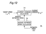
- FIG. 12 shows a structural example of the speed control unit 14 .
- the speed control unit 14 includes a current command calculation unit 71 and an average estimated speed calculation unit 72 .
- the average estimated speed calculation unit 72 calculates the average ⁇ ave of the estimated rotating speed ⁇ ⁇
- the current command calculation unit 71 calculates the current command 10 * so as to null the speed error of the rotating speed command ⁇ * given from outside and the average estimated speed ⁇ ave .
- the average estimated speed calculation unit 72 does not calculate the average, but directly feeds the estimated rotating speed value ⁇ ⁇ , while the current command calculation unit 71 calculates the current command I* so as to eliminate the speed difference of the rotating speed command ⁇ * given from outside and the estimated rotating speed value ⁇ ⁇ .
- ⁇ ave 1 nT s ⁇ ⁇ 0 nT s ⁇ ⁇ ⁇ ⁇ ⁇ t ( 20 )
- n is an integer.
- K p5 and K I5 are gains of the PI compensator.
- the current command I* is calculated in formula (2) without using the average estimated speed ⁇ ave .
- the average estimated speed calculation unit 72 associating with the correction action of the torque current as mentioned above, changes over its output to the average ⁇ ave of the estimated rotating speed ⁇ ⁇ , or the estimated rotating speed ⁇ ⁇ .
- the estimated speed ⁇ should be gradually changed, so as to prevent the estimated speed ⁇ from becoming discontinuous.
- the average estimated speed calculation unit 72 does not immediately issue the estimated speed average ⁇ ave ( ⁇ ⁇ ), but as shown in FIG. 13, after a grace period, its output (estimated rotating speed ⁇ ⁇ ) may be changed in gradual steps by a specific change ⁇ s so as to be closer gradually to the average estimated speed ⁇ ave ( ⁇ ⁇ ).
- the estimated speed ⁇ ⁇ of non-correction operation is smoothly connected to the value of the average estimated speed ⁇ ave ( ⁇ ⁇ ).
- the estimated speed may be changed over gradually by using the formulas (22), (23) only in this specific period.
- FIG. 14 shows a structural example of the current control unit 17 .
- the current control unit 17 includes a two-phase/three-phase converter 91 for converting current command of two phases i d * and i q * into current commands of three phases i u *, i v * and i w *, and a voltage command unit 92 for obtaining voltage commands of three phases v u *, v v * and v w * by using current commands of three phases i u *, i v * and i w *, and motor current detected values i u , i v , i w .
- K p6 , K I6 , K p7 and K I7 are gains of the PI compensator.
- FIG. 15 shows a structural example of the position and speed estimation unit 13 .
- the position and speed estimation unit 13 includes an induced voltage estimation unit 101 and a position error correction unit 103 .
- the induced voltage estimation unit 101 calculates estimated induced voltages e ⁇ u , e ⁇ v and e ⁇ w by using voltage commands of three phases v u *, v v * and v w * and detected motor currents i u , i v and i w , and also calculates induced voltages e u , e v and e ⁇ w from a motor model 102 provided inside.
- the position error correction unit 103 sequentially corrects the estimated position ⁇ ⁇ so as to eliminate the induced voltage error of the estimated induced voltages e ⁇ u , e ⁇ v and e ⁇ w , and induced voltages e u , e v and e w .
- induced voltage estimated values e ⁇ u , e ⁇ v and e ⁇ w are expressed in formula (9) and the induced voltages e u , e v and e w are expressed in formula (26).
- e w V G ⁇ [ nT s ] ⁇ sin ⁇ ( ⁇ ⁇ + 2 ⁇ ⁇ / 3 ) ( 26 )
- V G [nT s ] is sequentially calculated in formulas (27) to (29).
- [ e u0 e v0 e w0 ] ⁇ [ v u * v v * v w * ] - R ⁇ [ i u * i v * i w * ] + 3 2 ⁇ ⁇ ⁇ ⁇ L a0 ⁇ I * ⁇ [ sin ⁇ ( ⁇ ⁇ + ⁇ ) sin ⁇ ( ⁇ ⁇ + ⁇ - 2 ⁇ ⁇ / 3 ) sin ⁇ ( ⁇ ⁇ + ⁇ + 2 ⁇ ⁇ / 3 ) ] - ⁇ 3 2 ⁇ ⁇ ⁇ ⁇ L as ⁇ I * ⁇ [ sin ⁇ ( ⁇ ⁇ - ⁇ ) sin ⁇ ( ⁇ ⁇ - ⁇ - 2 ⁇ ⁇ / 3 ) sin ⁇ ( ⁇ ⁇ - ⁇ + 2 ⁇ ⁇ / 3 ) ] (
- V o ⁇ [ nT s ] m ⁇ V G ⁇ [ ( n - 1 ) ⁇ T s ] + ( 1 - m ) ⁇ e 0 m ( 29 )
- K e is a constant, and m is an integer.
- ⁇ ⁇ [nT 3 ] ⁇ ⁇ [( n ⁇ 1) T s ]+ ⁇ ⁇ [nT 3 ] (30)
- ⁇ 18 [nT s ] is expressed in formula (31) in terms of estimated position compensation amount ⁇ p .
- ⁇ ⁇ ⁇ [ nT s ] ⁇ K ⁇ ⁇ 1 ⁇ ⁇ ⁇ ⁇ [ ( n - 1 ) ⁇ T s ] + ⁇ p ( when ⁇ ⁇ advanced ) K ⁇ ⁇ 2 ⁇ ⁇ ⁇ ⁇ [ ( n - 1 ) ⁇ T s ] - ⁇ p ( when ⁇ ⁇ delayed ) ( 31 )
- K ⁇ 1 and K ⁇ 2 are constants.
- the position and speed can be estimated, and not only the inverter output limit can be increased, but also the stator winding of the synchronous reluctance motor can be wound by a greater number of turns, so that the efficiency of the entire driving system can be enhanced.
- the induced voltage estimated value is calculated by using a compensated motor constant, resulting in improved precision of position and speed estimation.
- FIG. 16 shows a configuration of induced voltage estimation unit 101 in the position and speed estimation unit 13 .
- the induced voltage estimation unit 101 includes an induced voltage estimation unit 111 and a motor constant compensator 112 .
- the motor constant compensator 112 compensates the motor constant by using the three-phase voltage command, detected motor current, and estimated speed.
- the induced voltage estimation unit 111 calculates the estimated induced voltage by using the three-phase voltage command, detected motor current, and compensated motor constant.
- ⁇ me is a actual rotating speed of a rotor.
- R ⁇ [nT s ] R ⁇ [( n ⁇ 1) T s ] ⁇ K R ⁇ n ⁇ 1)T s nTs ⁇ R ⁇ [( n ⁇ 1) T s ]i ⁇ 2 ⁇ ( v ⁇ i ⁇ ⁇ l d i ⁇ ⁇ pi ⁇ + ⁇ ⁇ L q i ⁇ i 67 ) ⁇ dt (35)
- K R is an integral gain
- each side of formula (35) can be divided by i ⁇ to shorten the calculation time.
- the invention can be also applied to other motor constants such as inductance and induced voltage constant.
- This embodiment relates to a configuration of the motor constant compensation unit in the position and speed estimation unit 13 shown in embodiment 8 for changing over on/off operation of compensation action of the motor constant depending on the speed.
- FIG. 17 shows a configuration of a motor constant compensator 112 .
- the motor constant compensator 112 includes an estimated speed comparator 42 for receiving and comparing the estimated rotating angle ⁇ 18 and a predetermined reference ⁇ R of the estimated rotating angle, and a motor constant compensation unit 121 for compensating the motor constant depending on the output signal of the estimated speed comparator 42 .
- the following explanation shows a case of compensation of the motor winding resistance value R which is one of motor constants.
- the output signal ⁇ w of the estimated speed comparator 42 is expressed in formula (13) from the estimated rotating angle ⁇ ⁇ and the reference estimated rotating angle ⁇ R .
- the output R out of the motor constant compensation unit 121 is expressed in formula (36) depending on the output signal ⁇ w of the estimated speed comparator 42 .
- R n ( ⁇ ⁇ I ) ( 36 )
- R ⁇ is the compensated motor winding resistance expressed in formula (35) and R n is nominal value.
- the motor constant compensator 112 compensates the motor constant only in the high speed region in which the estimated rotating angle ⁇ ⁇ is larger than the reference estimated rotating angle ⁇ R .
- the calculation time for compensation of the motor constant is substantially shortened, and the load capacity of the arithmetic operation device is lessened, and hence the cost is reduced and the peripheral circuits are simplified.
- the estimated speed comparator 42 may be provided with hysteresis. That is, in the estimated speed comparator 42 , the value of the reference ⁇ R when the estimated rotating angle ⁇ R changes in an increasing direction may be different from the value of the reference ⁇ R when the estimated rotating angle ⁇ ⁇ changes in a decreasing direction.
- the invention may be also applied to other motor constants such as inductance and induced voltage constant.
- FIG. 18 Other configuration of the motor constant compensator is shown in FIG. 18 .
- the torque fluctuation amount is detected, and the motor constant is compensated only in a region in which the fluctuation amount is equal to or smaller than the reference value. That is, the motor constant compensation action is turned on or off depending on the torque fluctuation amount.
- the motor constant compensator 112 b includes a torque fluctuation detector 51 , a torque fluctuation comparator 52 , and a motor constant compensation unit 121 .
- the torque fluctuation detector 51 detects the torque fluctuation ⁇ T by the estimated rotating angle ⁇ ⁇ .
- the torque fluctuation comparator 52 receives and compares the detected torque fluctuation ⁇ T and torque fluctuation reference ⁇ T R .
- the motor constant compensation unit 121 compensates the motor constant depending on the output signal of the torque fluctuation comparator 52 .
- the following explanation shows a case of the compensated motor winding resistance R ⁇ as one of motor constants.
- the detected torque fluctuation ⁇ T which is an output signal of the torque fluctuation detector 51 is expressed in formula (15) from the estimated rotating angle ⁇ ⁇ .
- the output signal ⁇ T of the torque fluctuation comparator is expressed in formula (16) from the detected torque fluctuation ⁇ T and the reference torque fluctuation ⁇ T R .
- the output R out of the motor constant compensation unit 121 is expressed in formula (37) depending on the output signal ⁇ ⁇ of the torque fluctuation comparator.
- R ⁇ is the compensated motor winding resistance expressed in formula (35) and R n is nominal value.
- the motor constant is compensated only in a region in which the detected torque fluctuation ⁇ T is smaller than the reference torque fluctuation ⁇ T R .
- the torque fluctuation comparator 52 may be provided with hysteresis.
- the invention may be also applied to other motor constants such as inductance and induced voltage constant.
- ⁇ R is a specified infinitesimal amount.
- a specific period may be determined, and it may be designed to change over the motor winding resistance value in gradual steps only in this specific period.
- control stability and reliability at the time of on/off changeover of motor constant compensation action can be enhanced, and disturbance or out-of-control of the motor can be prevented.
- detecting the voltage saturation rate of the synchronous reluctance motor it is designed to control to lower the target speed in order to avoid saturation when the voltage saturation rate is higher than a specified value.
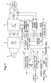
- FIG. 20 shows a configuration of a control apparatus of a synchronous reluctance motor of the embodiment.
- the control apparatus in this embodiment includes, in addition to the configuration of the control apparatus in embodiment 1, a voltage saturation recognition unit 31 for obtaining the degree of voltage saturation (voltage saturation rate) from the voltage command of the synchronous reluctance motor 4 .
- V R is the reference voltage (voltage set value when the voltage saturation rate is 100%)
- v ⁇ * and v y * are y- ⁇ axis voltage commands.
- the values of v ⁇ * and v y * are obtained from formula (6).
- the voltage saturation recognition unit 31 includes the voltage saturation rate ⁇ vol obtained in formula (40) and preset voltage compensation rate set value ⁇ R , and issues the result of comparison to the speed control unit 14 .
- the speed control unit 14 on the basis of the result of comparison from the voltage saturation recognition unit 31 , decreases the target rotating speed ⁇ * given from outside if ⁇ vol ⁇ R .
- a target rotating speed value ⁇ * is decreased by formula (41).
- the speed control unit 14 decreases the rotating speed target value ⁇ * until the voltage saturation rate becomes smaller than the reference value, and determines the current command by using the decreased value.
- V y * and v ⁇ * are nearly proportional to the rotating speed (in the synchronous motor or synchronous reluctance motor, rotating speed target value ⁇ motor actual rotating speed) (see formula (33) for example).
- the voltage saturation rate calculated in formula (40) can be lowered by lowering the rotating speed target value.
- FIG. 21 shows a configuration of a control apparatus of a synchronous reluctance motor of this embodiment.
- the control apparatus in the embodiment includes, in addition to the configuration of the control apparatus in embodiment 1, a voltage saturation recognition unit 31 for obtaining the degree of voltage saturation (voltage saturation rate) from the voltage command of the synchronous reluctance motor 4 , a DC voltage detector 33 for detecting the direct-current voltage applied into the inverter 3 (hereinafter referred to as “inverter DC voltage”), and a motor voltage correction unit 35 for correcting the motor voltage command so as to cancel ripples of the inverter DC voltage.
- inverter DC voltage direct-current voltage applied into the inverter 3
- the voltage saturation recognition unit 31 calculates the voltage saturation rate from the voltage command of the synchronous reluctance motor 4 , compares it with a predetermined voltage saturation rate set value, and outputs the result of comparison to the speed control unit 14 .
- the voltage saturation rate set value is corrected depending on pulsations of the inverter DC voltage. That is, the voltage saturation recognition unit 31 receives the detected value of the inverter DC voltage from the DC voltage detector 33 , and corrects the voltage saturation set value depending on the pulsations of the inverter DC voltage.
- ⁇ R is the predetermined voltage saturation rate set value
- V 0 is a predetermined reference of the inverter DC voltage
- the motor voltage correction unit 35 corrects the motor voltage command from the current control unit 17 on the basis of the inverter DC voltage Vdc detected by the DC voltage detector 33 , and thereby to reduce distortion of the motor current waveform.
- V j * is motor voltage command calculated by the current control unit 17
- V dc is the inverter DC voltage detected by the DC voltage detector 33
- V 0 is the predetermined reference of the inverter DC voltage (set at the maximum value of the inverter DC voltage).
- the speed control unit 14 on the basis of the result of comparison from the voltage saturation recognition unit 31 , decreases the rotating speed target value given from outside only when the voltage saturation rate calculated from the voltage command is equal to or larger than the voltage saturation rate set value, and determines the current command on the basis of this lowered target value.
- an inverter DC voltage pulsates at a double frequency of AC power supply frequency as shown in FIG. 22, and the voltage fluctuation width ⁇ V dc increases in proportion to the load torque generated by the load element. Accordingly, the actual motor applied voltage is decreased by the portion of the shaded area in FIG. 22, and the motor current waveform is distorted.
- the motor correction voltage command (motor applied voltage) reaches the maximum when the inverter DC voltage is the minimum (V 0 ⁇ V dc ) in FIG. 22 .
- the maximum value V jh — max of the corrected motor correction voltage command (motor applied voltage) is expressed in formula (44).
- v fh_max * v j * ⁇ V 0 V 0 - ⁇ ⁇ ⁇ v d ⁇ ⁇ c ( 44 )
- the voltage fluctuation rate ⁇ vol — max is calculated in formula (45) by three-phase to two-phase conversion of the maximum value of the corrected motor voltage command in formula (44).
- ⁇ vol_max V 0 V 0 - ⁇ ⁇ ⁇ v d ⁇ ⁇ c ⁇ v ⁇ * 2 + v ⁇ * 2 V R ( 45 )
- This formula indicates that the motor voltage command increases by correcting the pulsation of the inverter DC voltage, so that the voltage saturation rate is increased. That is, when the voltage saturation rate set value ⁇ R is constant, by correcting the pulsation of the inverter DC voltage, it is easy to transfer to the protection control of the voltage saturation, and the driving performance in high speed region is lowered.
- the inverter DC voltage reference value V 0 may not be a predetermined fixed value, but be the average of actual DC voltage detected value or the voltage set value of the AC/DC converter 2 , to correct the pulsation of the inverter DC voltage.
Abstract
A control apparatus of a synchronous reluctance motor includes a torque current correction unit (16) that generates a torque current command tracing a load torque so as to make the output torque of the motor coincide with the load torque. The control apparatus may further include a position and speed estimation unit (13) that estimates the position and speed based on three phase voltage equation to improve control performance in a voltage saturation state.
Description
This application is a U.S. National Phase of International Application No. PCT/JP03/03419, filed March 20, 2003, which claims priority to Japanese Application No. 2002-81171 filed March 22, 2002.
The present invention relates to a control apparatus of a synchronous reluctance motor, and more particularly to a control apparatus for driving the motor with estimation of the angle of the rotor without using position sensor.
A conventional control apparatus of a synchronous reluctance motor is designed to obtain the angle information of a rotor by using a position sensor such as Hall element, resolver or optical encoder. Accordingly, the cost is increased by the portion of the position sensor, and the size of the synchronous reluctance motor is also increased.
As a control apparatus of the synchronous reluctance motor for realizing low cost and small size by omitting position sensors, generally, a control apparatus of the synchronous reluctance motor as shown in FIG. 23 has been known.
In FIG. 23, a main circuit includes an alternating-current power source 1, an AC/DC converter 2 for converting an alternating-current power into a direct-current power, a DC/AC converter 3 for converting a direct-current power into an alternating-current power, and a synchronous reluctance motor 5 driving with the alternating-current power converted by the DC/AC converter 3.
On the other hand, a control circuit includes current detectors 11 a and 11 b and a motor current detector 12 for detecting the motor current, a position and speed estimation unit 13 for estimating the position and speed of the synchronous reluctance motor, a speed control unit 14 for determining a current command so as to eliminate the speed error between the speed command given from outside and the estimated speed obtained from the position and speed estimation unit 13, a conduction phase distribution unit 15 for distributing the current command obtained from the speed control unit 14 into a torque current component and a field current component, a current control unit 17 for determining the voltage command so as to eliminate the current error of the torque current command and field current command, and the detected motor current, and a conduction distribution unit 18 for distributing the conduction signal into driving elements in the synchronous reluctance motor 5.
FIG. 24 is a sectional view showing a structure of a general synchronous reluctance motor 5. The synchronous reluctance motor 5 is composed of a rotor 8 and a stator 6.
In the control apparatus shown in FIG. 23, the position and speed estimation unit 13 determines the magnetic flux by using the information of the motor current command and voltage command. Next, an α-β magnetic flux angle showing the angle based on the stationary coordinates of this magnetic flux is determined. Further, a d-q axis coordinate phase indicating the phase of this magnetic flux corresponding to the rotational coordinates is set. The d-q axis coordinate phase is subtracted from the α-β axis coordinate angle to obtain an estimated angle. On the basis of this estimated angle, the synchronous reluctance motor 5 is controlled.
Further, the angle is estimated in two methods of low speed angle estimation and high speed angle estimation, and in the boundary of low speed region and high speed region, the angles estimated by two methods are synthesized by gradually changing the rate of the estimated angles to generate an estimated angle. In the low speed region, a current pulse is applied and the angle is obtained from the voltage response.
For example, the synchronous reluctance motor of driving system without using position sensor disclosed in Japanese Laid-open Patent No. 2001-197774 has low pass filter means for applying a low pass function to the voltage command, and weakens the low pass function when the rotor speed increases to eliminate effects of voltage pulse in the boundary region of low and high speed regions and change over the angle estimating methods stably, realizing the control of synchronous reluctance motor free from time delay in high speed region.
In the conventional configuration, however, the control calculation is complicated, and if the voltage control rate of the inverter is over 100% to be in so-called voltage saturation, or if the load fluctuates extremely, it is difficult to estimate the position or speed, and the motor drive control is unstable.
The invention is intended to solve these problems of the prior art, and it is hence an object of the invention to present a control apparatus of the synchronous reluctance motor building up a robust control structure withstanding voltage saturation and steep load fluctuations.
The motor control apparatus according to the invention is an apparatus for controlling a synchronous reluctance motor by using a reluctance torque caused by at least a change in inductance of the stator winding and a motor current.
In the control apparatus, a current detector detects the motor current flowing in the stator winding of the synchronous motor.
A position and speed estimation unit estimates an induced voltage of the synchronous reluctance motor from the detected value by the current detector and a voltage command which is a command to a voltage to be applied to the stator winding of the synchronous reluctance motor, and estimated rotor position and rotating speed of the synchronous reluctance motor on the basis of the estimated induced voltage.
A speed control unit determines a current command which is a command to a current to be supplied to the stator winding of the synchronous reluctance motor so as to eliminate the error of the estimated rotating speed by the position and speed estimation unit and a target value of the rotating speed given from outside.
A distribution unit distributes the current command from the speed control unit into a torque current command which is a torque current component of the current command and a field current command which is a field current component of the current command, on the basis of a predetermined current phase angle of the synchronous reluctance motor.
A torque current correction unit corrects the torque current command on the basis of the torque current command from the distribution unit and the estimated rotating speed from the position and speed estimation unit, so that a load torque generated by a load element of the synchronous reluctance motor coincides with the output torque of the synchronous reluctance motor.
A current control unit generates a voltage command so as to eliminate the error between the corrected torque current command from the torque current correction unit and the detected motor current from the current detector, and the error between the field current command from the distribution unit and the detected motor current obtained from the current detector.
A conduction distribution unit distributes conduction signals into driving elements in the synchronous reluctance motor on the basis of the voltage command.
The control apparatus of the invention, having such configuration, controls so that the load torque generated by the load element of the synchronous reluctance motor may always coincide with the output torque of the synchronous reluctance motor. As a result, a robust control structure is built up withstanding steep load fluctuations, and torque fluctuations are suppressed, and lower vibration and lower noise are realized.
FIG. 1 is a diagram showing an example of an entire configuration of a control apparatus of a synchronous reluctance motor (SRM) according to the invention.
FIG. 2 is an explanatory diagram of an example of a coordinate in position and speed estimation.
FIG. 3 is a sectional view of one example of an permanent magnet assistance type synchronous reluctance motor according to the invention.
FIG. 4 is a sectional view of the other example of an permanent magnet assistance type synchronous reluctance motor according to the invention.
FIG. 5 is a diagram showing an example of magnetic flux vector of an permanent magnet assistance type synchronous reluctance motor according to the invention.
FIG. 6 is a diagram showing a load torque characteristic of a general rotary compressor.
FIG. 7 is a diagram showing an example of an output signal of a torque current correction unit in the control apparatus of SRM according to the invention.
FIG. 8 is a diagram showing a load torque characteristic of a general scroll compressor.
FIG. 9 is a block diagram showing one structural example of the torque current correction unit in the control apparatus of SRM according to the invention.
FIG. 10 is a block diagram showing the other structural example of the torque current correction unit in the control apparatus of SRM according to the invention.
FIG. 11 is a diagram showing a changeover mode of a torque current command at on/off changeover timing of torque current correction operation.
FIG. 12 is a block diagram showing an example of a configuration of the speed control unit in the control apparatus of SRM according to the invention.
FIG. 13 is a diagram showing a changeover mode of output of the average estimated speed unit in the control apparatus of SRM according to the invention.
FIG. 14 is a block diagram showing an example of a configuration of the current control unit in the control apparatus of SRM according to the invention.
FIG. 15 is a block diagram showing an example of a configuration of the position and speed estimation unit in the control apparatus of SRM according to the invention.
FIG. 16 is a block diagram showing an example of a configuration of the induced voltage estimation unit in the control apparatus of SRM according to the invention.
FIG. 17 is a block diagram showing an example of a configuration the motor constant compensation unit in the control apparatus of SRM according to the invention.
FIG. 18 is a block diagram showing other example of a configuration of the motor constant compensation unit in the control apparatus of SRM according to the invention.
FIG. 19 is a diagram showing a changeover mode of an output of the motor constant compensation unit at on/off changeover timing of motor constant compensation operation.
FIG. 20 is a diagram showing the other example of entire configuration of the control apparatus of the synchronous reluctance motor according to the invention.
FIG. 21 is a diagram showing still other example of entire configuration of the control apparatus of the synchronous reluctance motor according to the invention.
FIG. 22 is a diagram explaining ripple components of an inverter direct-current voltage.
FIG. 23 is a block diagram of a conventional control apparatus of synchronous reluctance motor.
FIG. 24 is a diagram showing a example of configuration of a conventional synchronous reluctance motor.
Referring now to the drawings, preferred embodiments of control apparatus of synchronous reluctance motor according to the invention are described below.
FIG. 1 is a system block diagram showing an embodiment of a control apparatus of a synchronous reluctance motor according to the invention. An example explained below is a case of sinusoidal drive of an permanent magnet assistance type synchronous reluctance motor by 180-degree conduction without using position sensor.
A main circuit includes an alternating-current power source 1, an AC/DC converter 2 for converting an alternating-current power into a direct-current power, a DC/AC converter 3 for converting a direct-current power into an alternating-current power, and an permanent magnet assistance type synchronous reluctance motor 4 driving with the alternating-current power converted by the DC/AC converter 3.
A control circuit includes current detectors 11 a, 11 b and motor current detector 12 for detecting the motor current, a position and speed estimation unit 13 for estimating the position and speed of the permanent magnet assistance type synchronous reluctance motor, a speed control unit 14 for determining the current command so as to eliminate the speed error between the speed command given from outside and the estimated speed obtained from the position and speed estimation unit 13, a conduction phase distribution unit 15 for distributing the current command obtained from the speed control unit 14 into a torque current component and a field current component, a torque current correction unit 16 for correcting the torque current command, a current control unit 17 for determining the voltage command so as to eliminate the current error between the corrected torque current command or field current command and detected motor current, and a conduction distribution unit 18 for distributing the conduction signal into driving elements in the permanent magnet assistance type synchronous reluctance motor 4.
FIG. 2 is a diagram of definition of axes of coordinates in position and speed estimation. Generally, in sinusoidal driving, for the ease of control operation, the motor parameters are converted from three phases of u, v and w to two phases of d and q to be in DC status. The converting method from three phases to two phases is well known and thus is not explained here. In FIG. 2, θme is actual rotor position (phase difference from q-axis based on u-phase) and θ˜ is an estimated position (phase difference from y-axis of u-phase). Position error Δθ is expressed as follows.
FIG. 3 and FIG. 4 show examples of structure of permanent magnet assistant type synchronous reluctance motor 4. The synchronous reluctance motor shown in FIG. 3 includes a distributed winding stator 6 and a rotor 8 having a permanent magnet 9. The synchronous reluctance motor shown in FIG. 4 includes a concentrated winding stator 7 and a rotor 8 having a permanent magnet 9. By incorporating a permanent magnet in the rotor, the motor efficiency is enhanced. The permanent magnet 9 is preferred to have a magnetic quantity of a minimum limit only necessary for canceling the brake torque at a rated load of the synchronous reluctance motor. As a result, not only the motor efficiency at a rated load is improved, but also the cost increase due to the permanent magnet is kept to a minimum.
An example of the magnetic flux vector of the permanent magnet assistant type synchronous reluctance motor 4 is shown in FIG. 5. In FIG. 5, the vector A is a magnetic flux component generating a positive torque, and a magnetic flux component (vector C) of assistant magnet acts to cancel a magnetic flux component (vector B) for generating a brake torque (negative torque). In this case, the generated torque is defined in formula (1).
where np is the number of pole pairs, Ld and Lq are d-axis and q-axis inductances, respectively, Λ0 is the number of flux interlinkages by the permanent magnet, and id and iq are d-axis and q-axis current respectively.
Driving of the permanent magnet assistant type synchronous reluctance motor 4 without a position sensor is explained below.
First, the speed control unit 14 determines the current command I* in the following formula, by using rotating speed command ω* given from outside and estimated rotating speed ω18. 
where Kp1, KI1 are gains of the PI compensator, and p is a differential operator.
The conduction phase distribution unit 15 distributes the current command I* into d-axis current id* and q-axis current iq0 in the following formula, by using the current command I* and predetermined current phase angle β. 
The torque current correction unit 16 calculates q-axis current command iq* in the following formula, by using the estimated rotating speed ω˜ and q-axis current iq0. 
In formula (4), a discrete time system is taken for operation by a microcomputer, in which nTs is a present sampling time, and (n−1)Ts is a sampling time one cycle before the present sampling time. Further, Kp2, KI2 are gains of the PI compensator. The torque current correction unit 16 obtains the q-axis current command iq* by using the formula above, so that the load torque generated by the load element of the permanent magnet assistant type synchronous reluctance motor may always coincide with the output torque of the permanent magnet assistant type synchronous reluctance motor.
The current control unit 17 calculates voltage commands of three phases vu*, vv* and vW* in the following formula, by using the motor current detected values iu, iv and iw, and d-q axis current commands id* and iq*.
First, as expressed in the formula below, by conversion from three phases into two phases, motor current detected values iu, iv and iw are converted into gamma-delta axis current detected values iγ, iδ. 
Next, using d-q axis current commands id* and iq*, and gamma-delta axis current detected values iγ, iδ, gamma-delta axis voltage commands vγ* and vδ* are calculated in formula (6). 
where Kp3, KI3, and Kp4, KI4 are gains of the PI compensator.
Finally, as expressed in the formula below, by conversion from two phases into three phases, the gamma-delta axis voltage commands vγ* and vδ* are converted into voltage commands of three phases vu*, vV* and vw*. 
Further, the position and speed estimation unit 13 estimates the position and speed in the following method, by using the voltage commands of three phases vu*, vv* and vw* and motor current detected values iu, iv and iw.
Herein, by the three-phase voltage equation, the induced voltage is expressed in formula (8).
In formula (8), the phase voltage, phase current, and induced voltage vuvw, iuvw, euvw are three-dimensional vectors, and the stator winding resistance and inductances R and L are expressed in a matrix with three columns and three rows, respectively.
Specifically, by the operation in formula (9), estimated induced voltages e˜ u, e˜ v and e˜ w are calculated. 
where La0=(Ld+Lq)/3, Las=(Lq−Ld)/3.
Induced voltages eu, ev and ew, can be expressed in formula (10), by using the estimated rotating speed ω˜ and induced voltage constant KE. 
Hence, from formulas (9) and (10), the estimated position θ˜ is obtained as in formula (11). 
where θ˜ u, θ˜ v and θ˜ w are expressed in formula (12). 
where δ0 is an infinitesimal term for prevention of zero division.
According to the control apparatus of the embodiment, in the case of a general rotary compressor for which the load element of the permanent magnet assistant type synchronous reluctance motor is expressed in FIG. 6, the torque current command conforming to the load torque as shown in FIG. 7 is generated by the torque current correction unit As a result, the output torque of the synchronous reluctance motor may always coincide with the load torque.
Or, in the case of a general scroll compressor in which the load element of the permanent magnet assistant type synchronous reluctance motor is shown in FIG. 8, according to the control apparatus of the embodiment, since load fluctuations during rotor the rotation are small, it is not usually required to correct the torque current command, and the amount of calculation can be saved substantially by employing a method of, for example, correcting the torque current command in a period of integer multiple times of the control period.
In this explanation, the permanent magnet assistant type synchronous reluctance motor is driven by the sinusoidal operation of 180-degree conduction without using the position sensor. However, since the permanent magnet is used in the rotor in the permanent magnet assistant type synchronous reluctance motor, it is also applicable in a square wave conduction with a position detection system employed in a general electric household appliance such as air conditioner.
Further, the control system of the permanent magnet assistant type synchronous reluctance motor is explained herein, but it is also applicable to a general synchronous reluctance motor.
Therefore, not only the load torque generated by the load element of the permanent magnet assistant type synchronous reluctance motor can be always matched with the output torque of the permanent magnet assistant type synchronous reluctance motor, but also a robust control system against voltage saturation or steep load fluctuations can be realized by estimating the position and speed with the three-phase voltage control equation, and thus torque fluctuations are suppressed to realize low vibration and low noise.
In this embodiment, the torque current command is corrected only in the low speed region in which the estimated rotating angle ω˜ is below the reference value. This embodiment differs from embodiment 1 only in the torque current correction unit. FIG. 9 shows a configuration of the torque current correction unit of this embodiment.
The torque current correction unit 16 a includes an estimated speed comparator 42 that receives and compares the estimated rotating angle ω˜ and a predetermined reference of the estimated rotating angle ωR, and a q-axis current correction unit 41 that corrects the torque current command depending on the output signal of the estimated speed comparator 42.
The output signal εw of the estimated speed comparator 42 is calculated as shown in formula (13), from the estimated rotating angle ω˜ and the reference estimated rotating angle ωR. 
The output value iq* of the q-axis current correction unit 41 is expressed in formula (14), depending on the output signal εw of the estimated speed comparator. 
That is, the torque current correction unit 16 executes correction of the torque current command (that is, to turn on torque current correction operation) only when the estimated rotating angle ω˜ is in a low speed region of less than the estimated rotating angle reference value ωR.
The estimated speed comparator 42 may be provided with hysteresis. That is, in the estimated speed comparator 42, the value of the reference value ωR when the estimated rotating angle ω˜ changes in an increasing direction may be different from the value of the reference value ωR when the estimated rotating angle ω˜ changes in a decreasing direction.
Further, in this explanation, only one reference estimated rotating angle ωR is mentioned, but plural reference estimated rotating angles may be specified, and correction or non-correction of the torque current command may be changed over in each rotating speed region specified by each reference value.
Therefore, the operation time for correction of torque current command is saved substantially, and the load capacity of the arithmetic operation device is lessened, and hence the cost can be reduced and the peripheral circuits can be simplified.
In this embodiment, the torque fluctuation amount is detected, and the torque current correction operation is turned on only in the region in which the torque fluctuation amount is larger than a reference value. This embodiment differs from embodiment 1 only in the torque current correction unit. A configuration of the torque current correction unit of the embodiment is shown in FIG. 10.
In the torque current correction unit 16 b, a torque fluctuation detector 51 detects a torque fluctuation ΔT from the estimated rotating angle ω˜. A torque fluctuation comparator 52 receives the detected torque fluctuation ΔT from the torque fluctuation detector 51 and a torque fluctuation reference ΔT R, and compares and outputs the result. The q-axis current correction unit 41 corrects the torque current command depending on the output signal of the torque fluctuation comparator 52.
Specifically, the detected torque fluctuation ΔT , that is, the output signal of the torque fluctuation detector 51 is calculated in formula (15) from the estimated rotating angle ω˜. 
where KT and TT are constants.
The output signal εT of the torque fluctuation comparator is expressed in formula (16), in terms of the detected torque fluctuation ΔT and the reference torque fluctuation ΔT R. 
The output value iq* of the q-axis current correction unit 41 is expressed as the following formula (17), depending on the output signal εT of the torque fluctuation comparator. 
That is, the torque current command is corrected only in a region of the detected torque fluctuation ΔT larger than the reference torque fluctuation ΔT R.
The torque fluctuation comparator 52 may be provided with hysteresis. That is, in the torque fluctuation comparator 52, the reference ΔT R when the detected torque fluctuation ΔT changes in an increasing direction may be different from the value of the reference ΔT R when the detected torque fluctuation value ΔT changes in a decreasing direction.
Further, in this explanation, only one reference torque fluctuation ΔT R is mentioned, but plural torque fluctuation references may be specified, and correction or non-correction of the torque current command may be changed over in each region determined by each reference value.
Therefore, the operation time for correction of torque current command is saved substantially, and the load capacity of the arithmetic operation device is lessened, and hence the cost can be reduced and the torque fluctuations can be suppressed efficiently.
In this embodiment, the torque current correction unit acts to prevent the torque current command iq* from changing suddenly when changing over from non-correction to correction of torque current so that the torque current command iq* may not be discontinuous. This changeover control is explained by referring to FIG. 11.
As shown in FIG. 11, a changeover grace period is provided when changing over from the current command (X) in a torque current non-correction operation (torque current correction OFF operation) to the current command (Y) in a torque current correction operation (torque current correction ON operation), thereby preventing the torque current command iq* from changing suddenly to be discontinuous.
Specifically, supposing the torque current command in non-correction operation to be i*q-off, the torque current command in correction operation to be i*q-on, and the present value of the torque current command to be i*q-now, when changing from the non-correction operation to correction operation, the present value of the torque current command i*q-now is expressed in formula (18). 
where Δiq is an infinitesimal amount, and is changed over to correction operation when satisfying the condition of i*q-now=i*q-on.
To the contrary, when changing over from the correction operation to non-correction operation, the present value of the torque current command i*q-now is expressed in formula (19). 
where it is changed over to the non-correction operation when satisfying the condition of i*q-now=i*q-off.
Incidentally, as the torque current correction changeover grace period, a maximum period may be determined preliminarily, and it may be designed to change over the torque current command in gradual steps only in the maximum period.
Thus, the control stability and reliability at the time of on/off changeover of torque current control can be enhanced and disturbance of the motor can be prevented.
FIG. 12 shows a structural example of the speed control unit 14. The speed control unit 14 includes a current command calculation unit 71 and an average estimated speed calculation unit 72. When the torque current correction is turned on, the average estimated speed calculation unit 72 calculates the average ωave of the estimated rotating speed ω˜, and the current command calculation unit 71 calculates the current command 10* so as to null the speed error of the rotating speed command ω* given from outside and the average estimated speed ωave. When the torque current correction is turned off, the average estimated speed calculation unit 72 does not calculate the average, but directly feeds the estimated rotating speed value ω˜, while the current command calculation unit 71 calculates the current command I* so as to eliminate the speed difference of the rotating speed command ω* given from outside and the estimated rotating speed value ω˜.
Specifically, the average estimated speed ωave is expressed in formula (20). 
where n is an integer.
When correcting the torque current command, the current command I0* expressed in formula (21) is calculated. 
where Kp5 and KI5 are gains of the PI compensator.
In non-correction operation of torque current command, the current command I* is calculated in formula (2) without using the average estimated speed ωave.
In the embodiment, when the torque current correction is turned on, in order to calculate the current command I0* by using the average estimated speed ωave. Thus, even if the torque fluctuation is large, the variation of the current command I0* is small, and deviation from the optimum driving point can be kept to a minimum limit. That is, by suppressing the variation of the current command issued from the speed control unit to a minimum limit when correcting the torque current command, deviation from the motor efficiency optimum point can be prevented; and operation of high efficiency is realized.
The average estimated speed calculation unit 72, associating with the correction action of the torque current as mentioned above, changes over its output to the average ωave of the estimated rotating speed ω˜, or the estimated rotating speed ω˜. In this case, at the time of on/off changeover of the correction action of the torque current command, preferably, the estimated speed ω should be gradually changed, so as to prevent the estimated speed ω from becoming discontinuous.
That is, when changed from the non-correction operation to correction operation of the torque current command, the average estimated speed calculation unit 72 does not immediately issue the estimated speed average ωave (ω˜), but as shown in FIG. 13, after a grace period, its output (estimated rotating speed ω˜) may be changed in gradual steps by a specific change Δωs so as to be closer gradually to the average estimated speed ωave(ω˜). As a result, upon changeover of non-correction and correction, the estimated speed ω˜ of non-correction operation is smoothly connected to the value of the average estimated speed ωave (ω˜).
Specifically, supposing the output speed of non-correction operation to be ωo-off (estimated rotating speed ω˜), the output speed in correction operation (estimated speed average value ωave ) to be ωo-on, and the present value of the output speed to be ωo-now, when changing over from the non-correction operation to the correction operation, the present value of the output speed ωo-now is expressed in formula (22). 
where ΔT s is a specified infinitesimal value. The output speed ωo-now is changed over to the value of the correction operation when satisfying the condition of ωo-now=ωo-on.
To the contrary, when changing over from correction operation to non-correction operation, the present value of the output speed ωo-now is expressed in formula (23). 
The output speed ωo-now is changed over to the value of the non-correction operation when satisfying the condition of ωo-now=ωo-off.
Besides, by determining a specific period as changeover grace period, the estimated speed may be changed over gradually by using the formulas (22), (23) only in this specific period.
By provision with the grace period for gradually changing the estimated speed in correction and/or non-correction operation, steep changes of estimated speed can be prevented, and the control stability and reliability in changeover time of correction and non-correction of the torque current command can be enhanced, and hunting due to steep changes of current command can be suppressed.
FIG. 14 shows a structural example of the current control unit 17. The current control unit 17 includes a two-phase/three-phase converter 91 for converting current command of two phases id* and iq* into current commands of three phases iu*, iv* and iw*, and a voltage command unit 92 for obtaining voltage commands of three phases vu*, vv* and vw* by using current commands of three phases iu*, iv* and iw*, and motor current detected values iu, iv, iw.
The current commands of three phases iu*, iv*, iw* are expressed in formula (24). 
The voltage commands of three phases vu*, vv* and vw* are expressed in formula (25). 
where Kp6, KI6, Kp7 and KI7 are gains of the PI compensator.
In this configuration, a more accurate voltage command can be generated, and distortion of motor current can be suppressed to a minimum limit, so that lower noise and lower vibration can be realized.
FIG. 15 shows a structural example of the position and speed estimation unit 13. The position and speed estimation unit 13 includes an induced voltage estimation unit 101 and a position error correction unit 103. The induced voltage estimation unit 101 calculates estimated induced voltages e˜ u, e˜ v and e˜ w by using voltage commands of three phases vu*, vv* and vw* and detected motor currents iu, iv and iw, and also calculates induced voltages eu, ev and e˜ w from a motor model 102 provided inside. The position error correction unit 103 sequentially corrects the estimated position θ˜ so as to eliminate the induced voltage error of the estimated induced voltages e˜ u, e˜ v and e˜ w, and induced voltages eu, ev and ew.
Specifically, induced voltage estimated values e˜ u, e˜ v and e˜ w are expressed in formula (9) and the induced voltages eu, ev and ew are expressed in formula (26). 
where VG[nTs] is sequentially calculated in formulas (27) to (29). 
e 0 =K 4(|eu0 |=e v0 =|e w0|) (28)

where Ke is a constant, and m is an integer.
The position error correction unit 103 sequentially corrects the estimated position θ˜ in formula (30) depending on the code information of the induced voltage error Δeuvw=e˜uvw−euvw.
where Δθ18 [nTs]is expressed in formula (31) in terms of estimated position compensation amount Δθp. 
where Kθ1 and Kθ2 are constants.
Hence, even if the voltage is saturated, the position and speed can be estimated, and not only the inverter output limit can be increased, but also the stator winding of the synchronous reluctance motor can be wound by a greater number of turns, so that the efficiency of the entire driving system can be enhanced.
In this embodiment, in the position and speed estimation unit 13 shown in embodiment 7, the induced voltage estimated value is calculated by using a compensated motor constant, resulting in improved precision of position and speed estimation.
FIG. 16 shows a configuration of induced voltage estimation unit 101 in the position and speed estimation unit 13. The induced voltage estimation unit 101 includes an induced voltage estimation unit 111 and a motor constant compensator 112.
The motor constant compensator 112 compensates the motor constant by using the three-phase voltage command, detected motor current, and estimated speed. The induced voltage estimation unit 111 calculates the estimated induced voltage by using the three-phase voltage command, detected motor current, and compensated motor constant. Explained below is a method of compensating the motor winging resistance as one of the motor constants, by the voltage equation on the d-q axis.
Specifically, the voltage equation on the d-q axis is expressed in formula (32). 
where ωme is a actual rotating speed of a rotor.
Herein, near the operating point, supposing the d-q axis and γ-δ axis (see FIG. 2) are nearly in coincidence, by approximating Δθ≈O, formula (32) is rewritten as in formula (33). 
Supposing the motor winding resistance compensated to be R˜, formula (33) is modified into formula (34).
Herein, from formula (34), regardless of the sign of i67 , the relation of the compensated value R˜ and true value R is determined, and when R˜ is greater than R, the right side is positive, while it is negative in a reverse case. Using formula (35), the motor winding resistance value is compensated.
where KR is an integral gain.
In formula (35), only the right side of formula (34) is integrated, but by PI compensation by adding proportional term, the response is enhanced.
When the sign of iδ is not changed, each side of formula (35) can be divided by iδ to shorten the calculation time.
Not limited to the motor winding resistance, the invention can be also applied to other motor constants such as inductance and induced voltage constant.
Accordingly, by using an accurate motor constant, not only the estimation precision of position and speed can be always enhanced, but also the power loss can be suppressed to a minimum limit.
This embodiment relates to a configuration of the motor constant compensation unit in the position and speed estimation unit 13 shown in embodiment 8 for changing over on/off operation of compensation action of the motor constant depending on the speed.
FIG. 17 shows a configuration of a motor constant compensator 112. The motor constant compensator 112 includes an estimated speed comparator 42 for receiving and comparing the estimated rotating angle ω18 and a predetermined reference ωR of the estimated rotating angle, and a motor constant compensation unit 121 for compensating the motor constant depending on the output signal of the estimated speed comparator 42.
The following explanation shows a case of compensation of the motor winding resistance value R which is one of motor constants.
The output signal εw of the estimated speed comparator 42 is expressed in formula (13) from the estimated rotating angle ω˜ and the reference estimated rotating angle ωR. The output Rout of the motor constant compensation unit 121 is expressed in formula (36) depending on the output signal εw of the estimated speed comparator 42. 
where R˜ is the compensated motor winding resistance expressed in formula (35) and Rn is nominal value.
As known from the above formula, the motor constant compensator 112 compensates the motor constant only in the high speed region in which the estimated rotating angle ω˜ is larger than the reference estimated rotating angle ωR. As a result, the calculation time for compensation of the motor constant is substantially shortened, and the load capacity of the arithmetic operation device is lessened, and hence the cost is reduced and the peripheral circuits are simplified.
The estimated speed comparator 42 may be provided with hysteresis. That is, in the estimated speed comparator 42, the value of the reference ωR when the estimated rotating angle ωR changes in an increasing direction may be different from the value of the reference ωR when the estimated rotating angle ω˜ changes in a decreasing direction.
Further, in this explanation, only one estimated rotating angle reference value ωR is mentioned, but plural estimated rotating angle references may be specified, and compensation or non-compensation of the motor constant may be changed over in each rotating speed region.
Further, not limited to the motor winding resistance, the invention may be also applied to other motor constants such as inductance and induced voltage constant.
Other configuration of the motor constant compensator is shown in FIG. 18. In this embodiment, the torque fluctuation amount is detected, and the motor constant is compensated only in a region in which the fluctuation amount is equal to or smaller than the reference value. That is, the motor constant compensation action is turned on or off depending on the torque fluctuation amount.
As shown in FIG. 18, the motor constant compensator 112 b includes a torque fluctuation detector 51, a torque fluctuation comparator 52, and a motor constant compensation unit 121. The torque fluctuation detector 51 detects the torque fluctuation ΔT by the estimated rotating angle ω˜. The torque fluctuation comparator 52 receives and compares the detected torque fluctuation ΔT and torque fluctuation reference ΔT R. The motor constant compensation unit 121 compensates the motor constant depending on the output signal of the torque fluctuation comparator 52.
The following explanation shows a case of the compensated motor winding resistance R˜ as one of motor constants.
The detected torque fluctuation ΔT which is an output signal of the torque fluctuation detector 51 is expressed in formula (15) from the estimated rotating angle ω˜. The output signal εT of the torque fluctuation comparator is expressed in formula (16) from the detected torque fluctuation ΔT and the reference torque fluctuation ΔT R. The output Rout of the motor constant compensation unit 121 is expressed in formula (37) depending on the output signal εγ of the torque fluctuation comparator. 
where R˜ is the compensated motor winding resistance expressed in formula (35) and Rn is nominal value.
As known from the above formula, the motor constant is compensated only in a region in which the detected torque fluctuation ΔT is smaller than the reference torque fluctuation ΔT R.
The torque fluctuation comparator 52 may be provided with hysteresis.
Further, in this explanation, only one torque fluctuation reference value ΔT R is mentioned, but plural torque fluctuation reference values may be specified, and compensation or non-compensation of the motor constant may be changed over in each region.
Further, not limited to the motor winding resistance, the invention may be also applied to other motor constants such as inductance and induced voltage constant.
As a result, the calculation time for compensation of motor constant is shortened to a required minimum limit, and the load capacity of the arithmetic operation device is lessened, and hence the cost is reduced substantially.
Embodiment 11
In embodiments 8 to 10, the on/off changeover control of compensation action of the motor constant in the motor constant compensator 112 is explained by referring to FIG. 19.
In this embodiment, in the motor constant compensation action in embodiments 8 to 10, when changed over from non-compensation (compensation action OFF) of the motor constant (motor winding resistance) to compensation (compensation action ON), as shown in FIG. 19, a grace period is provided for motor constant compensation changeover. As a result, steep changes of motor constant are suppressed to prevent the motor constant from being discontinuous.
Specifically, supposing the motor winding resistance in non-compensation to be Roff, motor winding resistance in compensation operation to be Ron, and present value of motor winding resistance to be Rnow, when changed from non-compensation to compensation operation, the present value of motor winding resistance Rnow issued from the motor constant compensation unit 121 is expressed in formula (38). 
where ΔR is a specified infinitesimal amount. The output from the motor constant compensation unit 121 is changed gradually in the grace period by ΔR each so as to approach the value Ron in the compensation operation, and when satisfying the condition of Rnow=Ron, it is changed over to the value Ron in the compensation operation.
To the contrary, when changing over from the compensation operation to non-compensation operation, the present value of the motor winding resistance Rnow issued from the motor constant compensation unit 121 is expressed in formula (39). 
That is, the output from the motor constant compensation unit 121 is changed gradually by ΔR each so as to approach the value of Roff in the non-compensation operation in the grace period, and when satisfying the condition of Rnow=Roff, it is changed over to the value of Roff in the non-compensation operation.
Incidentally, as the changeover grace period for motor constant compensation, a specific period may be determined, and it may be designed to change over the motor winding resistance value in gradual steps only in this specific period.
Thus, the control stability and reliability at the time of on/off changeover of motor constant compensation action can be enhanced, and disturbance or out-of-control of the motor can be prevented.
In this embodiment, detecting the voltage saturation rate of the synchronous reluctance motor, it is designed to control to lower the target speed in order to avoid saturation when the voltage saturation rate is higher than a specified value.
FIG. 20 shows a configuration of a control apparatus of a synchronous reluctance motor of the embodiment. The control apparatus in this embodiment includes, in addition to the configuration of the control apparatus in embodiment 1, a voltage saturation recognition unit 31 for obtaining the degree of voltage saturation (voltage saturation rate) from the voltage command of the synchronous reluctance motor 4.
The voltage saturation recognition unit 31 calculates the voltage saturation rate δvol in the following formula. 
where VR is the reference voltage (voltage set value when the voltage saturation rate is 100%), and vδ* and vy* are y-δ axis voltage commands. The values of vδ* and vy* are obtained from formula (6).
The voltage saturation recognition unit 31 includes the voltage saturation rate δvol obtained in formula (40) and preset voltage compensation rate set value δR, and issues the result of comparison to the speed control unit 14.
The speed control unit 14, on the basis of the result of comparison from the voltage saturation recognition unit 31, decreases the target rotating speed ω* given from outside if δvol≧δR. For example, a target rotating speed value ω* is decreased by formula (41).
The speed control unit 14 decreases the rotating speed target value ω* until the voltage saturation rate becomes smaller than the reference value, and determines the current command by using the decreased value.
In the operating region in which the voltage saturation occurs (mainly high speed region), Vy* and vδ* are nearly proportional to the rotating speed (in the synchronous motor or synchronous reluctance motor, rotating speed target value≈motor actual rotating speed) (see formula (33) for example). Thus, the voltage saturation rate calculated in formula (40) can be lowered by lowering the rotating speed target value.
Accordingly, by avoiding excessive voltage saturation, it is possible to avoid increase of error of estimated position θ˜ in the position and speed estimation unit, and out-of-control can be prevented.
FIG. 21 shows a configuration of a control apparatus of a synchronous reluctance motor of this embodiment. The control apparatus in the embodiment includes, in addition to the configuration of the control apparatus in embodiment 1, a voltage saturation recognition unit 31 for obtaining the degree of voltage saturation (voltage saturation rate) from the voltage command of the synchronous reluctance motor 4, a DC voltage detector 33 for detecting the direct-current voltage applied into the inverter 3 (hereinafter referred to as “inverter DC voltage”), and a motor voltage correction unit 35 for correcting the motor voltage command so as to cancel ripples of the inverter DC voltage.
The voltage saturation recognition unit 31 calculates the voltage saturation rate from the voltage command of the synchronous reluctance motor 4, compares it with a predetermined voltage saturation rate set value, and outputs the result of comparison to the speed control unit 14. At this time, in the voltage saturation recognition unit 31, the voltage saturation rate set value is corrected depending on pulsations of the inverter DC voltage. That is, the voltage saturation recognition unit 31 receives the detected value of the inverter DC voltage from the DC voltage detector 33, and corrects the voltage saturation set value depending on the pulsations of the inverter DC voltage. As a result, protection control in voltage saturation in consideration of pulsation component of the inverter DC voltage is realized. The correction value σRh of the voltage saturation set value is determined in the following formula. 
where σR is the predetermined voltage saturation rate set value, and V0 is a predetermined reference of the inverter DC voltage.
The motor voltage correction unit 35 corrects the motor voltage command from the current control unit 17 on the basis of the inverter DC voltage Vdc detected by the DC voltage detector 33, and thereby to reduce distortion of the motor current waveform. The corrected motor voltage command Vjh* is determined in the following formula. 
where j=u, v, w, Vj* is motor voltage command calculated by the current control unit 17, Vdc is the inverter DC voltage detected by the DC voltage detector 33, and V0 is the predetermined reference of the inverter DC voltage (set at the maximum value of the inverter DC voltage).
The speed control unit 14, on the basis of the result of comparison from the voltage saturation recognition unit 31, decreases the rotating speed target value given from outside only when the voltage saturation rate calculated from the voltage command is equal to or larger than the voltage saturation rate set value, and determines the current command on the basis of this lowered target value.
The reason for correcting the motor voltage command and voltage saturation rate set value on the basis of the inverter DC voltage Vdc is explained below.
Generally, an inverter DC voltage pulsates at a double frequency of AC power supply frequency as shown in FIG. 22, and the voltage fluctuation width ΔVdc increases in proportion to the load torque generated by the load element. Accordingly, the actual motor applied voltage is decreased by the portion of the shaded area in FIG. 22, and the motor current waveform is distorted.
Accordingly, concerning the motor voltage command Vj*, as shown in formula (43), by correcting the voltage shortage due to pulsation of the inverter DC voltage by using the inverter DC voltage detected value, the actual applied motor voltage is adjusted to a desired value as commanded.
Herein, the motor correction voltage command (motor applied voltage) reaches the maximum when the inverter DC voltage is the minimum (V0−ΔVdc) in FIG. 22. The maximum value Vjh — max of the corrected motor correction voltage command (motor applied voltage) is expressed in formula (44). 
where j=u, v, w.
At this time, the voltage fluctuation rate σvol — max is calculated in formula (45) by three-phase to two-phase conversion of the maximum value of the corrected motor voltage command in formula (44). 
This formula indicates that the motor voltage command increases by correcting the pulsation of the inverter DC voltage, so that the voltage saturation rate is increased. That is, when the voltage saturation rate set value σR is constant, by correcting the pulsation of the inverter DC voltage, it is easy to transfer to the protection control of the voltage saturation, and the driving performance in high speed region is lowered.
To prevent drop of driving performance in high speed region, it is required to correct also the voltage saturation rate set value σR based on pulsation of the inverter DC voltage as shown in formula (42). Thus, by correcting the voltage saturation rate set value σR, high speed operation is realized without lowering the driving performance, and the distortion of the motor current waveform decreases, and hence the efficiency and control stability are enhanced, and a further high speed operation is realized.
When the DC voltage setting is changed from 240 V (at 50 rps) to 280 V (at 100 rps) by the voltage control of the AC/DC converter 2, that is, if the value of the inverter DC voltage varies depending on the operating condition (for example, speed region), the inverter DC voltage reference value V0 may not be a predetermined fixed value, but be the average of actual DC voltage detected value or the voltage set value of the AC/DC converter 2, to correct the pulsation of the inverter DC voltage.
In this configuration, by decreasing the distortion of motor current waveform by keeping the actual motor applied voltage as commanded, not only numerous merits are obtained such as improvement of efficiency, reduction of noise and vibration, and enhancement of control stability (decrease of error of estimated position), but also by correcting the voltage saturation set value simultaneously based on pulsation of the inverter DC voltage, an equivalent or superior driving performance can be realized in the high speed region.
Having described preferred embodiments of the invention, it is to be understood that various changes and modifications may be effected therein by one skilled in the art hence the invention is not limited to these illustrated embodiments, but may be limited only by the scope or spirit of the appended claims.
Claims (21)
1. A motor control apparatus of a synchronous reluctance motor comprising:
a current detector that detects a motor current flowing in a stator winding of the synchronous reluctance motor;
a position and speed estimation unit that estimates an induced voltage of the synchronous reluctance motor from the detected value by the current detector and a voltage command which is a command to a voltage to be applied to the stator winding of the synchronous reluctance motor, and estimated rotor position and rotating speed of the synchronous reluctance motor on the basis of the estimated induced voltage;
a speed control unit that determines a current command which is a command to a current to be supplied to the stator winding of the synchronous reluctance motor so as to eliminate the error of the estimated rotating speed by the position and speed estimation unit and a target value of the rotating speed given from outside;
a distribution unit that distributes the current command from the speed control unit into a torque current command which is a torque current component of the current command and a field current command which is a field current component of the current command, on the basis of a predetermined current phase angle of the synchronous reluctance motor;
a torque current correction unit that corrects the torque current command on the basis of the torque current command from the distribution unit and the estimated rotating speed from the position and speed estimation unit, so that a load torque generated by a load element of the synchronous reluctance motor coincides with the output torque of the synchronous reluctance motor;
a current control unit that generates a voltage command so as to eliminate the error between the corrected torque current command from the torque current correction unit and the detected motor current from the current detector, and the error between the field current command from the distribution unit and the detected motor current obtained from the current detector; and
a conduction distribution unit that distributes conduction signals into driving elements in the synchronous reluctance motor on the basis of the voltage command.
2. The motor control apparatus of a synchronous reluctance motor according to claim 1 , wherein the torque current correction unit changes over a correcting operation for the torque current command, so that a correction to the torque current command is conducted when the estimated rotating speed from the position and speed estimation unit is smaller than a predetermined value, and the correction to the torque current command is not conducted when the estimated rotating speed obtained from the position and speed estimation unit is larger than the predetermined value.
3. The motor control apparatus of a synchronous reluctance motor according to claim 2 , wherein the torque current correction unit has a grace period to change over conduct and non-conduct of the correction operation of the torque current command, and during the grace period changes the torque current command gradually to be closer to the value obtained as the value after changeover.
4. The motor control apparatus of a synchronous reluctance motor according to claim 1 , wherein the torque current correction unit further includes a torque fluctuation detecting unit that detects temporal fluctuation of the load torque generated by the load element, and the torque current correction unit changes over a correction operation for the torque current command so as to conduct a correction of the torque current command when the torque fluctuation detected by the torque fluctuation detecting unit is larger than a predetermined value, and not to conduct the correction of the torque current command when the detected torque fluctuation is not larger than the predetermined value.
5. The motor control apparatus of a synchronous reluctance motor according to claim 4 , wherein the torque fluctuation detecting unit detects the torque fluctuation on the basis of the error of the estimated rotating speed in preceding and succeeding cycles consecutive in time.
6. The motor control apparatus of a synchronous reluctance motor according to claim 4 , wherein the torque current correction unit has a grace period to change over conduct and non-conduct of the correction operation of the torque current command, and during the grace period changes the torque current command gradually to be closer to the value obtained as the value after changeover.
7. The motor control apparatus of a synchronous reluctance motor according to claim 1 , wherein the speed control unit includes an average calculation unit that averages temporally the estimated values of the rotating speed from the position and speed estimation unit when the torque current command is corrected, and a command generating unit that generates the current command to be supplied to the stator winding of the synchronous reluctance motor so as to eliminate the error of the obtained average and the target value of the rotating speed.
8. The motor control apparatus of a synchronous reluctance motor according to claim 7 , wherein the average calculation unit outputs the average of estimated rotating speeds while a correction operation to the torque current command is conducted, and outputs the estimated value of the rotating speed from the position and speed estimation unit while a correction operation to the torque current command is not conducted, and
the average calculation unit has a grace period to change over conduct and non-conduct of the correction operation of the torque current command, and during the grace period changes it's output gradually to be closer to the value obtained as the value after changeover.
9. The motor control apparatus of a synchronous reluctance motor according to claim 1 , wherein the current control unit performs a coordinate transformation from two-phase current command to three-phase current command about the torque current command or the corrected torque current command and the field current command to generate a voltage command so as to eliminate a current error of the three-phase current command and the detected motor current.
10. The motor control apparatus of a synchronous reluctance motor according to claim 1 , wherein the position and speed estimation unit includes an induced voltage estimation unit that estimates an induced voltage of the synchronous reluctance motor on the basis of the detected motor current from the current detector and the voltage command,
an induced voltage generating unit that has a motor model of the synchronous reluctance motor in its inside and generates an induced voltage from the motor model, and
a position error correction unit that corrects the estimated induced value so as to eliminate the voltage error of the estimated induced voltage from the induced voltage estimation unit and the induced voltage from the induced voltage generating unit.
11. The motor control apparatus of a synchronous reluctance motor according to claim 10 , wherein the induced voltage estimation unit includes a motor constant compensation unit that compensates the motor constant of the synchronous reluctance motor by using the estimated rotating speed, the voltage command, and the detected motor current.
12. The motor control apparatus of a synchronous reluctance motor according to claim 11 , wherein the motor constant compensation unit compensates the motor constant when the estimated rotating speed is larger than a reference value.
13. The motor control apparatus of a synchronous reluctance motor according to claim 12 , wherein the motor constant compensation unit has a grace period to change over conduct and non-conduct of the compensation operation of the motor constant, and during the grace period changes the motor constant gradually to be closer to the value obtained as the value after changeover.
14. The motor control apparatus of a synchronous reluctance motor according to claim 11 , further comprising a torque fluctuation detecting unit that detects temporal fluctuation of the load torque generated by the load element,
wherein the motor constant compensation unit compensates the motor constant when the torque fluctuation from the torque fluctuation detecting unit is not larger than a reference value.
15. The motor control apparatus of a synchronous reluctance motor according to claim 14 , wherein the motor constant compensation unit has a grace period to change over conduct and non-conduct of the compensation operation of the motor constant, and during the grace period changes the motor constant gradually to be closer to the value obtained as the value after changeover.
16. The motor control apparatus of a synchronous reluctance motor according to claim 1 , further comprising a voltage saturation recognition unit that calculates a voltage saturation rate showing the degree of voltage saturation from the voltage command of the synchronous reluctance motor, and compares the voltage saturation rate with a predetermined value to output the comparison result,
wherein the speed control unit lowers the target value of the rotating speed given from outside when the voltage saturation rate is above the predetermined value on the basis of the output from the voltage saturation recognition unit, and determines the current command based on the lowered value.
17. The motor control apparatus of a synchronous reluctance motor according to claim 1 , further comprising:
a DC voltage detector that detects a direct-current voltage which is an input voltage to an inverter for supplying an alternating-current voltage to drive the synchronous reluctance motor,
a motor voltage correction unit that corrects the motor voltage command so as to cancel pulsations of the direct-current voltage, and
a voltage saturation recognition unit that calculates the voltage saturation rate showing the degree of voltage saturation from the motor correction voltage command, compares the calculated voltage saturation rate with a predetermined value, and outputs the comparison result,
wherein the voltage saturation recognition unit corrects the predetermined value based on the pulsations of the direct-current voltage detected by the DC voltage detector, and
the speed control unit lowers the target value of the rotating speed given from outside when the calculated voltage saturation rate is above the predetermined value, on the basis of the output from the voltage saturation recognition unit, and determines the current command on the basis of the lowered value.
18. The motor control apparatus of a synchronous reluctance motor according to claim 1 , wherein the rotor of the synchronous reluctance motor includes a permanent magnet.
19. The motor control apparatus of a synchronous reluctance motor according to claim 18 , wherein the permanent magnet has only an amount of magnet of minimum limit required for canceling the brake torque at the rated load of the synchronous reluctance motor.
20. The motor control apparatus of a synchronous reluctance motor according to claim 1 , wherein the stator of the synchronous reluctance motor is a concentrated winding stator.
21. The motor control apparatus of a synchronous reluctance motor according claim 1 , wherein the load element of the synchronous reluctance motor is at least rotary compressor or scroll compressor.
Applications Claiming Priority (4)
| Application Number | Priority Date | Filing Date | Title |
|---|---|---|---|
| JP2002081171 | 2002-03-22 | ||
| JP2002-081171 | 2002-03-22 | ||
| JP2002-81171 | 2002-03-22 | ||
| PCT/JP2003/003419 WO2003081765A1 (en) | 2002-03-22 | 2003-03-20 | Synchronous reluctance motor control device |
Publications (2)
| Publication Number | Publication Date |
|---|---|
| US20040201358A1 US20040201358A1 (en) | 2004-10-14 |
| US6822417B2 true US6822417B2 (en) | 2004-11-23 |
Family
ID=28449110
Family Applications (1)
| Application Number | Title | Priority Date | Filing Date |
|---|---|---|---|
| US10/481,059 Expired - Fee Related US6822417B2 (en) | 2002-03-22 | 2003-03-20 | Synchronous reluctance motor control device |
Country Status (6)
| Country | Link |
|---|---|
| US (1) | US6822417B2 (en) |
| EP (1) | EP1492223A4 (en) |
| JP (1) | JP4357967B2 (en) |
| KR (1) | KR20040090685A (en) |
| CN (1) | CN1516918A (en) |
| WO (1) | WO2003081765A1 (en) |
Cited By (42)
| Publication number | Priority date | Publication date | Assignee | Title |
|---|---|---|---|---|
| US20040207360A1 (en) * | 2003-03-25 | 2004-10-21 | Hideo Matsushiro | Inverter controller for driving motor, and air conditioner |
| US20040217728A1 (en) * | 2003-04-03 | 2004-11-04 | Mitsuo Kawaji | Inverter controller for driving motor and air conditioner using inverter controller |
| US20040228151A1 (en) * | 2003-03-28 | 2004-11-18 | Hideo Matsushiro | Inverter control device for driving a motor and an air conditioner |
| US20040232876A1 (en) * | 2003-03-27 | 2004-11-25 | Hideo Matsushiro | Inverter control device for driving a motor and an air conditioner |
| US20040232865A1 (en) * | 2003-05-22 | 2004-11-25 | Toyoda Koki Kabushiki Kaisha | Apparatus and method for controlling motor |
| US20040232877A1 (en) * | 2003-04-03 | 2004-11-25 | Mitsuo Kawaji | Inverter controller for driving motor and air conditioner using inverter controller |
| US20060032710A1 (en) * | 2003-02-27 | 2006-02-16 | Kone Corporation | Method and apparatus for adjustment of the rotor angle of an elevator motor |
| US20060076920A1 (en) * | 2004-09-30 | 2006-04-13 | Brother Kogyo Kabushiki Kaisha | Evaluation device and method for rotary drive, corrective manipulated variable setting device and method, control device and method, and program |
| US20060125437A1 (en) * | 2002-10-11 | 2006-06-15 | Daikin Industries, Ltd. | Motor control method and device thereof |
| US20070080655A1 (en) * | 2005-10-12 | 2007-04-12 | Tesch Tod R | Method, apparatus and article for detecting rotor position |
| US20070085508A1 (en) * | 2005-10-13 | 2007-04-19 | Denso Corporation | Method of estimating magnetic pole position in motor and apparatus of controlling the motor based on the estimated position |
| US20070084677A1 (en) * | 2005-09-02 | 2007-04-19 | Messier-Bugatti | Method of managing an electromechanical brake actuator in particular for aircraft |
| US20070159130A1 (en) * | 2006-01-11 | 2007-07-12 | Daigo Kaneko | Driving apparatus and driving system for electric motor |
| US20070257633A1 (en) * | 2006-05-04 | 2007-11-08 | Lg Electronics Inc. | Apparatus and method of controlling synchronous reluctance motor |
| US20070257626A1 (en) * | 2006-05-03 | 2007-11-08 | Lg Electronics Inc. | Apparatus for controlling high speed operation of motor and method thereof |
| US20070262739A1 (en) * | 2006-03-15 | 2007-11-15 | Anderson Troy A | Vertically-mounted garage door operator |
| US20070296371A1 (en) * | 2006-06-13 | 2007-12-27 | Denso Corporation | Position sensorless control apparatus for synchronous motor |
| US20080100254A1 (en) * | 2006-10-25 | 2008-05-01 | Rahman Khwaja M | Method and system for controlling synchronous motor drive systems |
| US20080152326A1 (en) * | 2006-12-21 | 2008-06-26 | Kabushiki Kaisha Toshiba | Motor positioning unit |
| US20080180055A1 (en) * | 2007-01-30 | 2008-07-31 | Rockwell Automation Technologies, Inc. | Systems and methods for improved motor drive power factor control |
| US20080296994A1 (en) * | 2007-05-31 | 2008-12-04 | General Electric Company | Synchronous reluctance machine |
| US20080297078A1 (en) * | 2007-04-26 | 2008-12-04 | Sanyo Electric Co., Ltd. | Motor Control Device |
| US20090146589A1 (en) * | 2006-07-07 | 2009-06-11 | Toyota Jidosha Kabushiki Kaisha | Motor Control Device and Vehicle Including the Same |
| US7567047B2 (en) * | 2004-06-30 | 2009-07-28 | Hamilton Sundstrand Corporation | Electric motor control strategies for using a low resolution position sensor |
| US20090237015A1 (en) * | 2008-03-19 | 2009-09-24 | Sanyo Electric Co., Ltd. | Motor Control Device |
| US20100001671A1 (en) * | 2008-07-04 | 2010-01-07 | Toyota Jidosha Kabushiki Kaisha | Motor drive control apparatus and method |
| US20100118569A1 (en) * | 2007-04-27 | 2010-05-13 | Mitsubishi Electric Corporation | Power conversion system |
| US20100281897A1 (en) * | 2007-11-16 | 2010-11-11 | Daikin Industries, Ltd. | Motor current calculation device and air conditioning apparatus |
| US20100315030A1 (en) * | 2009-06-11 | 2010-12-16 | Hamilton Sundstrand Corporation | Torque harmonic reduction control for switched reluctance machines |
| US20130181650A1 (en) * | 2010-10-08 | 2013-07-18 | Panasonic Corporation | Motor constant calculating method for pm motor, and motor constant calculating device |
| US20130293181A1 (en) * | 2012-05-07 | 2013-11-07 | Samsung Electro-Mechanics Co., Ltd. | Switching control apparatus for two phase switched reluctance motor and method thereof |
| US20130300328A1 (en) * | 2012-05-11 | 2013-11-14 | Samsung Electro-Mechanics Co., Ltd. | Switching control apparatus for two phase switched reluctance motor and method thereof |
| US20140028228A1 (en) * | 2012-07-25 | 2014-01-30 | System General Corporation | Control systems and methods for angle estimation of permanent magnet motors |
| US20140035505A1 (en) * | 2012-07-31 | 2014-02-06 | Caterpillar, Inc. | Hybrid Closed Loop Speed Control using Open Look Position for Electrical Machines Controls |
| TWI469501B (en) * | 2012-10-12 | 2015-01-11 | Univ Nat Taiwan Science Tech | A controlling method of synchronous reluctance motor |
| US9110451B2 (en) | 2010-11-11 | 2015-08-18 | Mitsubishi Electric Corporation | Motor control system and safety monitoring system therefor |
| US20160248355A1 (en) * | 2015-02-25 | 2016-08-25 | Electronics And Telecommunications Research Institute | Motor driving device, method for controling motor, and calculation device for calculating angle information of motor |
| US9543884B2 (en) * | 2009-06-10 | 2017-01-10 | Lg Electronics Inc. | Motor control device of air conditioner using distributed power supply |
| US20170254575A1 (en) * | 2014-08-26 | 2017-09-07 | Bsh Hausgeraete Gmbh | Method for braking a compressor, compressor of a refrigeration appliance, an air conditioning appliance or a heat pump, and refrigeration appliance, air conditioning appliance or heat pump having the compressor |
| US20190146453A1 (en) * | 2014-02-25 | 2019-05-16 | Panasonic Intellectual Property Management Co., Ltd. | Control apparatus of an electric motor |
| US11661646B2 (en) | 2021-04-21 | 2023-05-30 | General Electric Comapny | Dual phase magnetic material component and method of its formation |
| US11926880B2 (en) | 2021-04-21 | 2024-03-12 | General Electric Company | Fabrication method for a component having magnetic and non-magnetic dual phases |
Families Citing this family (36)
| Publication number | Priority date | Publication date | Assignee | Title |
|---|---|---|---|---|
| EP1341293A4 (en) * | 2000-11-09 | 2009-05-06 | Daikin Ind Ltd | Synchronous motor control method and device |
| US20040251860A1 (en) * | 2003-01-09 | 2004-12-16 | Mehrdad Ehsani | Advanced sensorless drive technique for brushless DC motors |
| JP4517793B2 (en) * | 2004-09-14 | 2010-08-04 | 株式会社日立製作所 | Permanent magnet synchronous motor control device and module |
| JP4581603B2 (en) * | 2004-09-29 | 2010-11-17 | パナソニック株式会社 | Electric motor drive |
| KR101031778B1 (en) * | 2004-10-21 | 2011-04-29 | 주식회사 만도 | Torque control apparatus of motor for torque ripple compensation |
| JP4641179B2 (en) * | 2004-11-25 | 2011-03-02 | 川崎重工業株式会社 | Synchronous motor control method and control apparatus |
| JP2006288076A (en) * | 2005-03-31 | 2006-10-19 | Toshiba Elevator Co Ltd | Control unit |
| JP4706324B2 (en) * | 2005-05-10 | 2011-06-22 | トヨタ自動車株式会社 | Control device for motor drive system |
| JP2007110779A (en) * | 2005-10-11 | 2007-04-26 | Matsushita Electric Ind Co Ltd | Motor drive and driving method |
| CN101467344B (en) * | 2006-04-24 | 2012-05-23 | 松下电器产业株式会社 | Inverter device and air conditioner |
| JP4805329B2 (en) * | 2008-11-07 | 2011-11-02 | ファナック株式会社 | Control device for calculating power consumption of industrial machinery |
| JP5526975B2 (en) * | 2009-05-13 | 2014-06-18 | 株式会社安川電機 | Electric motor control device and control method thereof |
| DE102010041021A1 (en) * | 2010-09-20 | 2012-03-22 | Robert Bosch Gmbh | Method and device for sensorless determination of a rotor position of an electrical machine |
| KR101139028B1 (en) * | 2010-11-03 | 2012-04-27 | 경성대학교 산학협력단 | Torque control method for high speed switched reluctance motor |
| GB201109348D0 (en) * | 2011-06-03 | 2011-07-20 | Trw Ltd | Motor control with voltage harmonic shaping |
| DE102012204751B4 (en) | 2012-03-26 | 2018-12-20 | Robert Bosch Gmbh | Method for checking a field current measurement of a synchronous machine in generator mode |
| CN103368474B (en) * | 2012-03-27 | 2015-12-02 | 比亚迪股份有限公司 | A kind of motor speed control method |
| DE112012006959T5 (en) * | 2012-09-28 | 2015-06-18 | Mitsubishi Electric Corporation | Heat pump device, air conditioning and freezer |
| CN103840725B (en) * | 2012-11-26 | 2016-05-18 | 台达电子工业股份有限公司 | Permanent-magnet synchronous motor rotor position deviation measurement device and method |
| JP2014147170A (en) * | 2013-01-28 | 2014-08-14 | Shimadzu Corp | Motor drive for vacuum pump and vacuum pump |
| US9577555B2 (en) * | 2014-04-02 | 2017-02-21 | Deere & Company | Methods of estimating a position of a rotor in a motor under transient and systems thereof |
| CN103973188B (en) * | 2014-05-22 | 2017-02-15 | 阳光电源股份有限公司 | electromagnetic torque control circuit and method |
| CN104615149B (en) * | 2014-11-27 | 2017-04-05 | 北京航空航天大学 | The anti-saturation control method of servomotor under the conditions of a kind of control input amplitude and rate-constrained |
| WO2016121751A1 (en) * | 2015-01-28 | 2016-08-04 | 株式会社 東芝 | Inverter control apparatus and motor driving system |
| US9762155B1 (en) | 2016-05-24 | 2017-09-12 | Texas Instruments Incorporated | Rotor flux angle and torque trajectory control apparatus and methods |
| JP6369517B2 (en) * | 2016-09-30 | 2018-08-08 | ダイキン工業株式会社 | Control device for power converter |
| CN106559026B (en) * | 2016-11-30 | 2019-02-05 | 广东美的制冷设备有限公司 | A kind of control method of motor driven systems, control device and transducer air conditioning |
| KR101888842B1 (en) * | 2017-01-02 | 2018-08-16 | 엘지전자 주식회사 | Apparatus for controlling motor and control method of apparatus for controlling motor |
| CN106877747A (en) * | 2017-02-07 | 2017-06-20 | 上海仙知机器人科技有限公司 | A kind of driver and driving method |
| JP6990085B2 (en) * | 2017-10-03 | 2022-01-12 | マブチモーター株式会社 | Rotation speed calculation device |
| DE112018006843T5 (en) | 2018-01-12 | 2020-10-01 | Mitsubishi Electric Corporation | ROTARY MACHINE CONTROL DEVICE |
| US11218100B2 (en) * | 2018-01-12 | 2022-01-04 | Mitsubishi Electric Corporation | Rotary machine control device |
| CN108194338B (en) * | 2018-01-15 | 2022-03-25 | 杭州先途电子有限公司 | Compressor driving voltage saturation control method and device |
| CN112567620B (en) * | 2018-08-30 | 2024-03-01 | 日立安斯泰莫株式会社 | Inverter device |
| CN110595552B (en) * | 2019-10-15 | 2021-03-16 | 王元西 | Method for non-magnetic acquisition of displacement and angular velocity of planar winding coil |
| CN113472258B (en) * | 2021-06-15 | 2023-07-18 | 江苏大学 | Electric excitation vehicle-mounted motor controller |
Citations (11)
| Publication number | Priority date | Publication date | Assignee | Title |
|---|---|---|---|---|
| US5585709A (en) * | 1993-12-22 | 1996-12-17 | Wisconsin Alumni Research Foundation | Method and apparatus for transducerless position and velocity estimation in drives for AC machines |
| US5694010A (en) * | 1994-06-14 | 1997-12-02 | Kabushiki Kaisha Toshiba | Method and apparatus for controlling a brushless DC motor |
| JPH10243699A (en) | 1997-02-27 | 1998-09-11 | Fuji Electric Co Ltd | Synchronous motor controller |
| JP2000245199A (en) | 1999-02-24 | 2000-09-08 | Matsushita Electric Ind Co Ltd | Motor controller |
| JP2000358400A (en) | 1999-06-11 | 2000-12-26 | Okuma Corp | Control device of synchronous electric motor |
| US6208109B1 (en) * | 1996-08-19 | 2001-03-27 | Hiroyuki Yamai | Synchronous motor driving method, compressor driving method, device for the methods, and brushless DC motor driving device |
| JP2001197774A (en) | 2000-01-17 | 2001-07-19 | Matsushita Electric Ind Co Ltd | Control device of synchronous reluctance motor |
| US20020097015A1 (en) * | 2000-11-22 | 2002-07-25 | Nissan Motor Co., Ltd. | Motor control apparatus and motor control method |
| US6433506B1 (en) * | 2001-03-29 | 2002-08-13 | Ford Global Technologies, Inc. | Sensorless control system for induction motor employing direct torque and flux regulation |
| US20020113569A1 (en) * | 2000-10-11 | 2002-08-22 | Matsushita Industrial Co., Ltd. | Method and apparatus for position-sensorless motor control |
| US20030001536A1 (en) * | 2001-06-29 | 2003-01-02 | Nissan Motor Co., Ltd. | Motor control apparatus |
Family Cites Families (5)
| Publication number | Priority date | Publication date | Assignee | Title |
|---|---|---|---|---|
| US5125236A (en) * | 1989-09-15 | 1992-06-30 | Onan Corporation | Combined generator set and air conditioning compressor drive system |
| JP3428896B2 (en) * | 1998-05-07 | 2003-07-22 | オークマ株式会社 | Motor with reduced torque ripple |
| JP3454212B2 (en) * | 1999-12-02 | 2003-10-06 | 株式会社日立製作所 | Motor control device |
| JP3328636B2 (en) * | 2000-03-17 | 2002-09-30 | オークマ株式会社 | Vector control method for synchronous reluctance motor |
| KR100354775B1 (en) * | 2000-03-25 | 2002-11-04 | 엘지전자 주식회사 | Speed control apparatus of a synchronous reluctance motor |
-
2003
- 2003-03-20 CN CNA038004321A patent/CN1516918A/en active Pending
- 2003-03-20 WO PCT/JP2003/003419 patent/WO2003081765A1/en not_active Application Discontinuation
- 2003-03-20 KR KR10-2003-7016165A patent/KR20040090685A/en not_active Application Discontinuation
- 2003-03-20 EP EP03710451A patent/EP1492223A4/en not_active Withdrawn
- 2003-03-20 JP JP2003579355A patent/JP4357967B2/en not_active Expired - Fee Related
- 2003-03-20 US US10/481,059 patent/US6822417B2/en not_active Expired - Fee Related
Patent Citations (15)
| Publication number | Priority date | Publication date | Assignee | Title |
|---|---|---|---|---|
| US5585709A (en) * | 1993-12-22 | 1996-12-17 | Wisconsin Alumni Research Foundation | Method and apparatus for transducerless position and velocity estimation in drives for AC machines |
| US5694010A (en) * | 1994-06-14 | 1997-12-02 | Kabushiki Kaisha Toshiba | Method and apparatus for controlling a brushless DC motor |
| US6153993A (en) * | 1994-06-14 | 2000-11-28 | Kabushiki Kaisha Toshiba | Method and apparatus for controlling a brushless DC motor that indicates a motor failure |
| US6208109B1 (en) * | 1996-08-19 | 2001-03-27 | Hiroyuki Yamai | Synchronous motor driving method, compressor driving method, device for the methods, and brushless DC motor driving device |
| JPH10243699A (en) | 1997-02-27 | 1998-09-11 | Fuji Electric Co Ltd | Synchronous motor controller |
| JP2000245199A (en) | 1999-02-24 | 2000-09-08 | Matsushita Electric Ind Co Ltd | Motor controller |
| JP2000358400A (en) | 1999-06-11 | 2000-12-26 | Okuma Corp | Control device of synchronous electric motor |
| JP2001197774A (en) | 2000-01-17 | 2001-07-19 | Matsushita Electric Ind Co Ltd | Control device of synchronous reluctance motor |
| US20020113569A1 (en) * | 2000-10-11 | 2002-08-22 | Matsushita Industrial Co., Ltd. | Method and apparatus for position-sensorless motor control |
| US6583593B2 (en) * | 2000-10-11 | 2003-06-24 | Matsushita Electric Industrial Co., Ltd. | Method and apparatus for position-sensorless motor control |
| US20020097015A1 (en) * | 2000-11-22 | 2002-07-25 | Nissan Motor Co., Ltd. | Motor control apparatus and motor control method |
| US6674262B2 (en) * | 2000-11-22 | 2004-01-06 | Nissan Motor Co., Ltd. | Motor control apparatus and motor control method |
| US6433506B1 (en) * | 2001-03-29 | 2002-08-13 | Ford Global Technologies, Inc. | Sensorless control system for induction motor employing direct torque and flux regulation |
| US20030001536A1 (en) * | 2001-06-29 | 2003-01-02 | Nissan Motor Co., Ltd. | Motor control apparatus |
| US6768280B2 (en) * | 2001-06-29 | 2004-07-27 | Nissan Motor Co., Ltd. | Motor control apparatus |
Cited By (72)
| Publication number | Priority date | Publication date | Assignee | Title |
|---|---|---|---|---|
| US20060125437A1 (en) * | 2002-10-11 | 2006-06-15 | Daikin Industries, Ltd. | Motor control method and device thereof |
| US7579800B2 (en) * | 2002-10-11 | 2009-08-25 | Sumitomo Electric Industries, Ltd. | Motor control method and device thereof |
| US7121385B2 (en) * | 2003-02-27 | 2006-10-17 | Kone Corporation | Method and apparatus for adjustment of the rotor angle of an elevator motor |
| US20060032710A1 (en) * | 2003-02-27 | 2006-02-16 | Kone Corporation | Method and apparatus for adjustment of the rotor angle of an elevator motor |
| US20040207360A1 (en) * | 2003-03-25 | 2004-10-21 | Hideo Matsushiro | Inverter controller for driving motor, and air conditioner |
| US6924618B2 (en) * | 2003-03-25 | 2005-08-02 | Matsushita Electric Industrial Co., Ltd. | Inverter controller for driving motor, and air conditioner |
| US20040232876A1 (en) * | 2003-03-27 | 2004-11-25 | Hideo Matsushiro | Inverter control device for driving a motor and an air conditioner |
| US6972541B2 (en) * | 2003-03-27 | 2005-12-06 | Matsushita Electric Industrial Co., Ltd. | Inverter control device for driving a motor and an air conditioner |
| US20040228151A1 (en) * | 2003-03-28 | 2004-11-18 | Hideo Matsushiro | Inverter control device for driving a motor and an air conditioner |
| US7113414B2 (en) * | 2003-03-28 | 2006-09-26 | Matsushita Electric Industrial Co., Ltd. | Inverter control device for driving a motor and an air conditioner |
| US20040232877A1 (en) * | 2003-04-03 | 2004-11-25 | Mitsuo Kawaji | Inverter controller for driving motor and air conditioner using inverter controller |
| US7095208B2 (en) * | 2003-04-03 | 2006-08-22 | Matsushita Electric Industrial Co., Ltd. | Inverter controller for driving motor and air conditioner using inverter controller |
| US6958589B2 (en) * | 2003-04-03 | 2005-10-25 | Matsushita Electric Industrial Co., Ltd. | Inverter controller for driving motor and air conditioner using inverter controller |
| US20040217728A1 (en) * | 2003-04-03 | 2004-11-04 | Mitsuo Kawaji | Inverter controller for driving motor and air conditioner using inverter controller |
| US7102305B2 (en) * | 2003-05-22 | 2006-09-05 | Toyoda Koki Kabushiki Kaisha | Apparatus and method for controlling motor |
| US20040232865A1 (en) * | 2003-05-22 | 2004-11-25 | Toyoda Koki Kabushiki Kaisha | Apparatus and method for controlling motor |
| US7567047B2 (en) * | 2004-06-30 | 2009-07-28 | Hamilton Sundstrand Corporation | Electric motor control strategies for using a low resolution position sensor |
| US20060076920A1 (en) * | 2004-09-30 | 2006-04-13 | Brother Kogyo Kabushiki Kaisha | Evaluation device and method for rotary drive, corrective manipulated variable setting device and method, control device and method, and program |
| US7679303B2 (en) * | 2004-09-30 | 2010-03-16 | Brother Kogyo Kabushiki Kaisha | Evaluation device and method for rotary drive, corrective manipulated variable setting device and method, control device and method, and program |
| US7523812B2 (en) * | 2005-09-02 | 2009-04-28 | Messier-Bugatti | Method of managing an electromechanical brake actuator in particular for aircraft |
| US20070084677A1 (en) * | 2005-09-02 | 2007-04-19 | Messier-Bugatti | Method of managing an electromechanical brake actuator in particular for aircraft |
| US20070080655A1 (en) * | 2005-10-12 | 2007-04-12 | Tesch Tod R | Method, apparatus and article for detecting rotor position |
| US7557530B2 (en) * | 2005-10-12 | 2009-07-07 | Continental Automotive Systems Us, Inc. | Method, apparatus and article for detecting rotor position |
| US20070085508A1 (en) * | 2005-10-13 | 2007-04-19 | Denso Corporation | Method of estimating magnetic pole position in motor and apparatus of controlling the motor based on the estimated position |
| US7352151B2 (en) * | 2005-10-13 | 2008-04-01 | Denso Corporation | Method of estimating magnetic pole position in motor and apparatus of controlling the motor based on the estimated position |
| US20070159130A1 (en) * | 2006-01-11 | 2007-07-12 | Daigo Kaneko | Driving apparatus and driving system for electric motor |
| US7602138B2 (en) * | 2006-01-11 | 2009-10-13 | Hitachi Industrial Equipment Systems Co., Ltd. | Driving apparatus and driving system for electric motor |
| US20070262739A1 (en) * | 2006-03-15 | 2007-11-15 | Anderson Troy A | Vertically-mounted garage door operator |
| US20070257626A1 (en) * | 2006-05-03 | 2007-11-08 | Lg Electronics Inc. | Apparatus for controlling high speed operation of motor and method thereof |
| US7501776B2 (en) * | 2006-05-03 | 2009-03-10 | Lg Electronics Inc. | Apparatus for controlling high speed operation of motor and method thereof |
| US20070257633A1 (en) * | 2006-05-04 | 2007-11-08 | Lg Electronics Inc. | Apparatus and method of controlling synchronous reluctance motor |
| US20070296371A1 (en) * | 2006-06-13 | 2007-12-27 | Denso Corporation | Position sensorless control apparatus for synchronous motor |
| US8013556B2 (en) * | 2006-07-07 | 2011-09-06 | Toyota Jidosha Kabushiki Kaisha | Motor control device and vehicle including the same |
| US20090146589A1 (en) * | 2006-07-07 | 2009-06-11 | Toyota Jidosha Kabushiki Kaisha | Motor Control Device and Vehicle Including the Same |
| US7592765B2 (en) * | 2006-10-25 | 2009-09-22 | Gm Global Technology Operations, Inc. | Method and system for controlling synchronous motor drive systems |
| US20080100254A1 (en) * | 2006-10-25 | 2008-05-01 | Rahman Khwaja M | Method and system for controlling synchronous motor drive systems |
| US7564206B2 (en) * | 2006-12-21 | 2009-07-21 | Kabushiki Kaisha Toshiba | Motor positioning unit |
| US20080152326A1 (en) * | 2006-12-21 | 2008-06-26 | Kabushiki Kaisha Toshiba | Motor positioning unit |
| US20080180055A1 (en) * | 2007-01-30 | 2008-07-31 | Rockwell Automation Technologies, Inc. | Systems and methods for improved motor drive power factor control |
| US7495410B2 (en) * | 2007-01-30 | 2009-02-24 | Rockwell Automation Technologies, Inc. | Systems and methods for improved motor drive power factor control |
| US8198846B2 (en) * | 2007-04-26 | 2012-06-12 | Sanyo Electric Co., Ltd. | Motor control device |
| US20080297078A1 (en) * | 2007-04-26 | 2008-12-04 | Sanyo Electric Co., Ltd. | Motor Control Device |
| US20100118569A1 (en) * | 2007-04-27 | 2010-05-13 | Mitsubishi Electric Corporation | Power conversion system |
| US8547713B2 (en) * | 2007-04-27 | 2013-10-01 | Mitsubishi Electric Corporation | Power conversion system |
| US7652404B2 (en) * | 2007-05-31 | 2010-01-26 | General Electric Company | Synchronous reluctance machine |
| US20080296994A1 (en) * | 2007-05-31 | 2008-12-04 | General Electric Company | Synchronous reluctance machine |
| US20100281897A1 (en) * | 2007-11-16 | 2010-11-11 | Daikin Industries, Ltd. | Motor current calculation device and air conditioning apparatus |
| US20090237015A1 (en) * | 2008-03-19 | 2009-09-24 | Sanyo Electric Co., Ltd. | Motor Control Device |
| US8269436B2 (en) * | 2008-03-19 | 2012-09-18 | Sanyo Electric Co., Ltd. | Motor control device |
| US20100001671A1 (en) * | 2008-07-04 | 2010-01-07 | Toyota Jidosha Kabushiki Kaisha | Motor drive control apparatus and method |
| US8164287B2 (en) * | 2008-07-04 | 2012-04-24 | Toyota Jidosha Kabushiki Kaisha | Motor drive control apparatus and method |
| US9543884B2 (en) * | 2009-06-10 | 2017-01-10 | Lg Electronics Inc. | Motor control device of air conditioner using distributed power supply |
| US8080969B2 (en) * | 2009-06-11 | 2011-12-20 | Hamilton Sundstrand Corporation | Torque harmonic reduction control for switched reluctance machines |
| US20100315030A1 (en) * | 2009-06-11 | 2010-12-16 | Hamilton Sundstrand Corporation | Torque harmonic reduction control for switched reluctance machines |
| US9024562B2 (en) * | 2010-10-08 | 2015-05-05 | Panasonic Intellectual Property Management Co., Ltd. | Motor constant calculating method for PM motor, and motor constant calculating device |
| US20130181650A1 (en) * | 2010-10-08 | 2013-07-18 | Panasonic Corporation | Motor constant calculating method for pm motor, and motor constant calculating device |
| US9110451B2 (en) | 2010-11-11 | 2015-08-18 | Mitsubishi Electric Corporation | Motor control system and safety monitoring system therefor |
| US9059656B2 (en) * | 2012-05-07 | 2015-06-16 | Samsung Electro-Mechanics Co., Ltd. | Switching control apparatus for two phase switched reluctance motor and method thereof |
| US20130293181A1 (en) * | 2012-05-07 | 2013-11-07 | Samsung Electro-Mechanics Co., Ltd. | Switching control apparatus for two phase switched reluctance motor and method thereof |
| US20130300328A1 (en) * | 2012-05-11 | 2013-11-14 | Samsung Electro-Mechanics Co., Ltd. | Switching control apparatus for two phase switched reluctance motor and method thereof |
| US20140028228A1 (en) * | 2012-07-25 | 2014-01-30 | System General Corporation | Control systems and methods for angle estimation of permanent magnet motors |
| US9219432B2 (en) * | 2012-07-25 | 2015-12-22 | System General Corporation | Control systems and methods for angle estimation of permanent magnet motors |
| US8901869B2 (en) * | 2012-07-31 | 2014-12-02 | Caterpillar Inc. | Hybrid closed loop speed control using open look position for electrical machines controls |
| US20140035505A1 (en) * | 2012-07-31 | 2014-02-06 | Caterpillar, Inc. | Hybrid Closed Loop Speed Control using Open Look Position for Electrical Machines Controls |
| TWI469501B (en) * | 2012-10-12 | 2015-01-11 | Univ Nat Taiwan Science Tech | A controlling method of synchronous reluctance motor |
| US10579038B2 (en) * | 2014-02-25 | 2020-03-03 | Panasonic Intellectual Property Management Co., Ltd. | Control apparatus of an electric motor |
| US20190146453A1 (en) * | 2014-02-25 | 2019-05-16 | Panasonic Intellectual Property Management Co., Ltd. | Control apparatus of an electric motor |
| US10174980B2 (en) * | 2014-08-26 | 2019-01-08 | Bsh Hausgeraete Gmbh | Method for braking a compressor, compressor of a refrigeration appliance, an air conditioning appliance or a heat pump, and refrigeration appliance, air conditioning appliance or heat pump having the compressor |
| US20170254575A1 (en) * | 2014-08-26 | 2017-09-07 | Bsh Hausgeraete Gmbh | Method for braking a compressor, compressor of a refrigeration appliance, an air conditioning appliance or a heat pump, and refrigeration appliance, air conditioning appliance or heat pump having the compressor |
| US20160248355A1 (en) * | 2015-02-25 | 2016-08-25 | Electronics And Telecommunications Research Institute | Motor driving device, method for controling motor, and calculation device for calculating angle information of motor |
| US11661646B2 (en) | 2021-04-21 | 2023-05-30 | General Electric Comapny | Dual phase magnetic material component and method of its formation |
| US11926880B2 (en) | 2021-04-21 | 2024-03-12 | General Electric Company | Fabrication method for a component having magnetic and non-magnetic dual phases |
Also Published As
| Publication number | Publication date |
|---|---|
| EP1492223A1 (en) | 2004-12-29 |
| KR20040090685A (en) | 2004-10-26 |
| US20040201358A1 (en) | 2004-10-14 |
| WO2003081765A1 (en) | 2003-10-02 |
| CN1516918A (en) | 2004-07-28 |
| JP4357967B2 (en) | 2009-11-04 |
| EP1492223A4 (en) | 2005-12-14 |
| JPWO2003081765A1 (en) | 2005-07-28 |
Similar Documents
| Publication | Publication Date | Title |
|---|---|---|
| US6822417B2 (en) | Synchronous reluctance motor control device | |
| US6650081B2 (en) | Synchronous motor driving system | |
| JP5130031B2 (en) | Position sensorless control device for permanent magnet motor | |
| EP1876702B1 (en) | Motor control device | |
| EP2034605B1 (en) | Electric motor driving device, and compressor driving device | |
| US10161766B2 (en) | Magnetic pole position detection device of permanent magnet-type synchronous motor | |
| US6414462B2 (en) | Speed control apparatus for synchronous reluctance motor | |
| US6771039B2 (en) | Motor control apparatus and method | |
| US20060176005A1 (en) | Motor-drive control device and electric power steering device using the same | |
| EP1519046B1 (en) | Apparatus for compensating for speed error of motor | |
| US20020149342A1 (en) | Electric motor controller | |
| US5726549A (en) | Sensor-less control apparatus for permanent magnet synchronous motor | |
| EP2234261B1 (en) | Power conversion device, power conversion device module, air conditioner, and freezing device | |
| US6927551B2 (en) | Motor control apparatus and motor control method | |
| JP2003219678A (en) | Synchronous electric motor driving device | |
| JP3397013B2 (en) | Control device for synchronous motor | |
| KR100563225B1 (en) | Induction Motor Control System | |
| US6838843B2 (en) | Controller for DC brushless motor | |
| JPH10337100A (en) | Method and apparatus for controlling buried magnet type synchronous motor | |
| JPH09238492A (en) | Control equipment of ac motor | |
| JP2003250293A (en) | Method and apparatus for controlling motor | |
| JP5228435B2 (en) | Inverter control device and control method thereof | |
| JP2003158886A (en) | Motor controller | |
| JP3576509B2 (en) | Motor control device | |
| JP3557855B2 (en) | Reluctance motor torque control device |
Legal Events
| Date | Code | Title | Description |
|---|---|---|---|
| FEPP | Fee payment procedure |
Free format text: PAYOR NUMBER ASSIGNED (ORIGINAL EVENT CODE: ASPN); ENTITY STATUS OF PATENT OWNER: LARGE ENTITY |
|
| AS | Assignment |
Owner name: MATSUSHITA ELECTRIC INDUSTRIAL CO., LTD., JAPAN Free format text: ASSIGNMENT OF ASSIGNORS INTEREST;ASSIGNORS:KAWAJI, MITSUO;MATSUSHIRO, HIDEO;MATSUI, KEIZO;REEL/FRAME:016161/0280;SIGNING DATES FROM 20040126 TO 20040202 |
|
| REMI | Maintenance fee reminder mailed | ||
| LAPS | Lapse for failure to pay maintenance fees | ||
| STCH | Information on status: patent discontinuation |
Free format text: PATENT EXPIRED DUE TO NONPAYMENT OF MAINTENANCE FEES UNDER 37 CFR 1.362 |
|
| FP | Lapsed due to failure to pay maintenance fee |
Effective date: 20081123 |