US6748094B1 - Connector system for BTE hearing devices - Google Patents
Connector system for BTE hearing devices Download PDFInfo
- Publication number
- US6748094B1 US6748094B1 US09/785,629 US78562901A US6748094B1 US 6748094 B1 US6748094 B1 US 6748094B1 US 78562901 A US78562901 A US 78562901A US 6748094 B1 US6748094 B1 US 6748094B1
- Authority
- US
- United States
- Prior art keywords
- auxiliary
- connector
- contact
- bte
- bushing
- Prior art date
- Legal status (The legal status is an assumption and is not a legal conclusion. Google has not performed a legal analysis and makes no representation as to the accuracy of the status listed.)
- Expired - Lifetime, expires
Links
Images


Classifications
-
- H—ELECTRICITY
- H04—ELECTRIC COMMUNICATION TECHNIQUE
- H04R—LOUDSPEAKERS, MICROPHONES, GRAMOPHONE PICK-UPS OR LIKE ACOUSTIC ELECTROMECHANICAL TRANSDUCERS; DEAF-AID SETS; PUBLIC ADDRESS SYSTEMS
- H04R25/00—Deaf-aid sets, i.e. electro-acoustic or electro-mechanical hearing aids; Electric tinnitus maskers providing an auditory perception
- H04R25/60—Mounting or interconnection of hearing aid parts, e.g. inside tips, housings or to ossicles
- H04R25/607—Mounting or interconnection of hearing aid parts, e.g. inside tips, housings or to ossicles of earhooks
-
- H—ELECTRICITY
- H04—ELECTRIC COMMUNICATION TECHNIQUE
- H04R—LOUDSPEAKERS, MICROPHONES, GRAMOPHONE PICK-UPS OR LIKE ACOUSTIC ELECTROMECHANICAL TRANSDUCERS; DEAF-AID SETS; PUBLIC ADDRESS SYSTEMS
- H04R2225/00—Details of deaf aids covered by H04R25/00, not provided for in any of its subgroups
- H04R2225/021—Behind the ear [BTE] hearing aids
- H04R2225/0213—Constructional details of earhooks, e.g. shape, material
-
- H—ELECTRICITY
- H04—ELECTRIC COMMUNICATION TECHNIQUE
- H04R—LOUDSPEAKERS, MICROPHONES, GRAMOPHONE PICK-UPS OR LIKE ACOUSTIC ELECTROMECHANICAL TRANSDUCERS; DEAF-AID SETS; PUBLIC ADDRESS SYSTEMS
- H04R25/00—Deaf-aid sets, i.e. electro-acoustic or electro-mechanical hearing aids; Electric tinnitus maskers providing an auditory perception
- H04R25/55—Deaf-aid sets, i.e. electro-acoustic or electro-mechanical hearing aids; Electric tinnitus maskers providing an auditory perception using an external connection, either wireless or wired
- H04R25/554—Deaf-aid sets, i.e. electro-acoustic or electro-mechanical hearing aids; Electric tinnitus maskers providing an auditory perception using an external connection, either wireless or wired using a wireless connection, e.g. between microphone and amplifier or using Tcoils
Definitions
- the present invention relates to hearing devices for aiding the hearing impaired and the profoundly deaf, and more particularly to a dual purpose connector system providing an attachment system for both a standard earhook and for a special earhook, which special earhook includes auxiliary accessory electrical connection capabilities.
- the connector system of the present invention is useful for both conventional hearing aids and for cochlear stimulation systems employing Behind-The-Ear (BTE) speech processors.
- BTE Behind-The-Ear
- Implantable Cochlear Stimulation (ICS) systems are known in the art. Such systems are used to help the profoundly deaf (those whose middle and/or outer ear is dysfunctional, but whose auditory nerve remains intact) to hear. The sensation of hearing is achieved by directly exciting the auditory nerve with controlled impulses of electrical current, which impulses are generated as a function of perceived audio sounds. The audio sounds are picked up by a microphone carried externally (not implanted) by the deaf person and converted to electrical signals.
- the electrical signals are processed and conditioned by a Wearable Signal Receiver and Processor (WP) in an appropriate manner, e.g., converted to a sequence of pulses of varying width and/or amplitude, and then transmitted to an implanted receiver circuit of the ICS system.
- WP Wearable Signal Receiver and Processor
- the implanted receiver circuit generates electrical current as a function of the processed signal it receives from the WP (which in turn is based on the audio sounds picked up by the external microphone).
- the implanted receiver circuit is connected to an implantable electrode array that has been inserted into the cochlea of the inner ear.
- the electrical current generated by the implanted receiver circuit is applied to individual electrode pairs of the electrode array. It is this electrical current which directly stimulates the auditory nerve and provides the user with the sensation of hearing.
- ICS systems While known ICS systems have succeeded in providing hearing to the deaf, ICS systems also have the disadvantage of appearing unsightly.
- ICS systems include an external headpiece positioned on the side of the user's head, and require an external cable running from the external headpiece to the WP.
- the WP is typically worn or carried by the user on a belt or in a pocket. While the WP is not too large, it is likewise not extremely small, and hence also represents an inconvenience for the user.
- the cable which connects the WP with the headpiece is particularly a source of irritation and self-consciousness for the user.
- the present invention addresses the above and other needs by providing a connector system for Behind-The-Ear (BTE) hearing devices.
- the connector system serves as an attachment system for both standard earhooks and for special earhooks, and provides an electrical connection system for auxiliary devices.
- the connector system comprises a coaxial connector on the BTE device and an auxiliary connector on an earhook.
- the auxiliary connector on the earhook screws onto the coaxial connector, thus mounting the earhook to the BTE device.
- the connection of the auxiliary connector to the coaxial connector further provides an electrical connection for a variety of auxiliary devices.
- the connector system may be utilized as part of either a hearing aid system or a Behind-The-Ear (BTE) speech processor of a cochlear stimulation system.
- a threaded coaxial connector protruding from the body of a BTE device for the connection of an earhook.
- Various sizes and shapes of earhooks are required to comfortably fit a BTE device to a particular user.
- the connector system of the present invention provides a means to easily attach and remove various earhooks.
- the threads of the threaded coaxial connector accept either a standard earhook or a special earhook.
- auxiliary devices include: telecoils, auxiliary microphones, FM receivers, audio jacks, etc.
- auxiliary devices include: telecoils, auxiliary microphones, FM receivers, audio jacks, etc.
- an appropriate type of connector must be used.
- An unprotected male connector, for example, would create a risk of snagging on hair and other objects.
- a female connector would reduce the interior volume of the BTE device available for BTE electronics. Either connector type would result in an unsightly feature on the BTE case.
- incorporating the auxiliary device electrical connector into the earhook attachment fixture alleviates the need for a separate connector.
- auxiliary devices include: telecoils, auxiliary microphones, FM receivers, audio jacks, etc.
- auxiliary devices include: telecoils, auxiliary microphones, FM receivers, audio jacks, etc.
- an appropriate type of connector must be used.
- An unprotected male connector, for example, would create a risk of snagging on hair and other objects.
- a female connector would reduce the interior volume of the BTE device available for BTE electronics. Either connector type would result in an unsightly feature on the BTE case.
- incorporating the auxiliary device electrical connector into the earhook attachment fixture alleviates the need for a separate connector.
- a telecoil cooperates with a transmitting coil in a telephone handset to provide a received telephone signal directly to a BTE device.
- the location of the transmitting coil is generally in the speaker end of the telephone handset.
- the telecoil may be positioned in front of the ear and therefore proximal to the transmitting coil in the handset.
- an auxiliary microphone may be positioned proximal to the ear canal.
- the shape of the ear provides frequency coloring of sound that varies due to the direction the sound arrives from.
- the frequency coloring enables the brain to determine the direction of sound arrival.
- a further feature of the invention is that an FM receiver may be built into an earhook to provide the reception of FM radio signals.
- FM links are a known method of providing a signal from a remote device to a BTE device, as described in detail in the '022 patent referenced above.
- Such remote devices include a remote microphone that may be placed near a lecturer for better reception of speech. Placement of the FM receiver in the earhook provides greater freedom in designing the receiver, and isolation from electronics within the BTE device.
- a further feature provided by the invention is that auxiliary devices contained in the special earhook are located in front of the ear, and thereby provide better weight distribution than when the auxiliary devices are attached directly to the BTE.
- FIG. 1A depicts a complete Behind-The-Ear (BTE) device with earhook and battery attached;
- BTE Behind-The-Ear
- FIG. 1B shows a connector made in accordance with the present invention attached to a BTE device
- FIG. 2A illustrates cross-sectional views of a standard earhook and four special earhooks, which earhooks may be interchangeably attached to the BTE device;
- FIG. 2B illustrates a cross sectional view of a special earhook for use with conventional BTE, or other hearing aid devices, that positions a receiver (speaker) proximal to the ear canal;
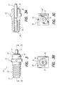
- FIG. 3 depicts a coaxial connector made in accordance with the present invention
- FIG. 3A shows a cross sectional view of the coaxial connector of FIG. 3 taken along line 3 A— 3 A of FIG. 3;
- FIG. 3B shows a front view of the connector of FIG. 3;
- FIG. 3C shows a rear view of the connector of FIG. 3;
- FIG. 4 depicts a contact assembly
- FIG. 4A shows a cross-sectional view of the contact assembly shown in FIG. 4 taken along line 4 A— 4 A of FIG. 4;
- FIG. 5 illustrates an auxiliary connector that may be used in special earhooks in accordance with the invention
- FIG. 6 shows a perspective view of an alternative coaxial connector system comprising a cooperating ring and ring groove as means for earhook retention;
- FIG. 6A shows a side view of an alternative auxiliary connector
- FIG. 6B shows a cross-sectional view of the alternative auxiliary connector of FIG. 6A taken along line 6 B— 6 B of FIG. 6 A;
- the connector system for Behind-The-Ear (BTE) hearing devices of the present invention provides both a mechanical attachment fixture for standard earhooks and for special earhooks, and an electrical connection for auxiliary devices.
- a standard earhook 12 and BTE device 10 resemble a common BTE hearing aid.
- the standard earhook 12 is arched and hooks in front of the ear.
- the BTE device 10 continues the arch and is positioned behind the ear.
- a battery compartment 14 is removably attached to the bottom of the BTE device 10 .
- Various batteries of different sizes may be interchangeably attached to the BTE device 10 depending upon the needs of a user.
- a more detailed description of a BTE device may be found in U.S. Pat. No. 5,824,022, previously incorporated herein by reference.
- the BTE device 10 is small and fits compactly behind the user's ear, and as a result, there is limited surface area available on the BTE to add connectors.
- a male connector would risk snagging the user's hair or clothing and a female connector would take up valuable space inside the BTE device that is also needed for BTE electronic circuits. Both male and female connectors would also require covering when not in use to prevent soiling.
- a coaxial connector 16 is shown attached to the BTE device 10 .
- the coaxial connector 16 serves as both an attaching fixture for the standard and special earhooks (i.e., provides a mechanical connection), and as an electrical connector for auxiliary devices (i.e., provides an electrical connection between the BTE electronics circuits and other electronic devices or sensors included within, or attached to, an earhook).
- the dual use feature of the coaxial connector 16 eliminates the need to provide a separate connector for connecting (electrically or mechanically) auxiliary devices to the BTE device 10 .
- the coaxial connector 16 preferably uses the same thread size and pitch as is known for use in standard earhooks, thus allowing the use of standard earhooks with the BTE device.
- an earhook surface 35 and a BTE surface 36 provide a friction fit between the standard earhook 12 and BTE device 10 . That is, as the standard earhook 12 is screwed onto the coaxial connector 16 , the earhook surface 35 comes into contact with the BTE surface 36 during the final turn of an installation. The resulting resistance or friction resists further turning, and thereby allows the standard earhook 12 to be positioned over a small range of rotational positions. This range positions allows the user to adjust the earhook to a most comfortable position, and the friction fit retains the earhook in that position.
- a plurality of special earhooks may be used to provide auxiliary functions to the BTE device 10 , as shown in FIG. 2 A.
- the standard earhook 12 comprises a bore 38 threaded to receive a standard sized thread.
- the standard earhook 12 with its threaded bore 38 , screws on to the coaxial connector 16 to mount the earhook, just like a nut screws onto a bolt.
- the standard earhook 12 contains no electronics or other auxiliary components that require an electrical connection.
- a special earhook 12 a has a telecoil 18 embedded within the earhook.
- An auxiliary connector 40 is also included as part of the special earhook 12 a .
- the auxiliary connector 40 both screws onto the coaxial connector 16 to mechanically mount the special earhook, and provides an electrical connection for leads 42 running from the telecoil 18 to the auxiliary connector 40 .
- Yet another special earhook 12 b also shown in FIG. 2A, includes an auxiliary microphone 20 mounted near the tip of the earhook (i.e., the end of the earhook opposite the BTE device). Wires or leads 42 electrically connect the microphone 20 to the auxiliary connector 40 .
- another special earhook 12 c has an FM receiver 22 embedded therein. Wires or leads 42 electrically connect the FM receiver 22 to the auxiliary connector 40 .
- FIG. 2 A Another special earhook 12 d , having a cable 24 extending to an input plug 23 is also shown in FIG. 2 A. Wires or leads 42 embedded within the special earhook 12 d electrically connect the cable 24 to the auxiliary connector 40 .
- auxiliary devices may be similarly connected to the BTE device 10 using special earhooks similar to the special earhooks 12 a , 12 b , 12 c , and 12 d shown in FIG. 2 A.
- Such other special earhook devices are intended to fall within the scope of the present invention.
- FIG. 2B a special earhook 12 e adapted for use with conventional hearing aids is shown.
- Known hearing aids utilize a receiver (the hearing aid's speaker) in the body of the hearing aid, and a passage through an earhook to carry the sound to a user.
- the microphone of the hearing aid is also located in the hearing aid body. Because both the microphone and speaker are physically close to each other, some acoustic coupling (feedback) exists between the microphone and the receiver, thus degrading performance.
- the special earhook 12 e shown in FIG. 2B positions the hearing aid receiver 25 (i.e., speaker) near the tip of the earhook, and thus proximal or close to the user's ear, and isolated from the microphone in the hearing aid case.
- Leads or wires 42 carry the signal from the auxiliary connector 40 to the receiver 25 .
- FIG. 3 A side view of the coaxial connector 16 , shown before mounting within the BTE device 10 , is shown in FIG. 3 .
- the coaxial connector 16 is mounted in the BTE device 10 such that male threads 44 extend or protrude from the mounting surface 36 (FIG. 1B) of the BTE device 10 .
- a square shoulder 45 at the base of the male threads 44 facilitate mounting the connector 16 within or on the surface 36 .
- using a square shoulder 45 provides a means to rotationally index the coaxial connector 16 relative to the BTE device 10 . Such indexing allows a range of frictionally fixed rotational positions of the earhook relative to the BTE device, to be centered on the average position.
- FIG. 3A shows a cross sectional view of the coaxial connector 16 taken along line 3 A— 3 A of FIG. 3 .
- the connector body 26 is preferably made of bronze, but may be constructed from other conductive material with suitable mechanical strength and other material characteristics suitable for use as an electrical connector.
- a cylindrically shaped forward end of the connector body 26 protrudes out from BTE device 10 .
- Male threads 44 are provided on the forward end of the connector body 26 to provide for mounting an earhook to the BTE device 10 .
- the male threads 44 are preferably number 4 machine screw threads with 40 threads per inch, i.e., #4-40 threads.
- the #4-40 threads are the correct threads for mounting a standard off-the-shelf earhook.
- a passage about 0.050 inches in diameter is provided coaxial with the connector body, to accept a first bushing 28 and a second bushing 30 .
- the bushings are preferably made from PEI resin, but other materials with suitable electrical and mechanical characteristics may be used.
- a contact assembly 31 is preferably an off-the-shelf battery contact probe, part no. 100803-00, available from Interconnect Devices, Inc., of Kansas City, Kans., or an equivalent contact.
- the exterior surface of the contact assembly 31 has a diameter of about 0.034 inches, and is insulatedly supported by the bushings 28 and 30 .
- the bushing bore must be sufficiently large to permit easy assembly.
- the contact assembly 31 protrudes from a rearward end of the connector body 26 and into the body of the BTE device 10 , thus permitting an electrical lead within the BTE device 10 to be attached to the contact assembly 31 .
- a second lead within the BTE device 10 may be connected to the connector body 26 .
- the connector body 26 , first and second bushing 28 and 30 , and contact assembly 31 are assembled with any suitable glue or adhesive.
- FIG. 3B a front view of the coaxial connector 16 is depicted.
- the square shoulder 45 of the connector body 26 is shown.
- the square section permits the coaxial connector to be accurately positioned within the BTE device 10 , and provides counter rotational resistance.
- FIG. 3 C A rear view of the coaxial connector 16 is shown in FIG. 3 C.
- the square shoulder 45 is shown as well as smaller square step 45 ′, on the rear of the connector body 26 .
- the contact assembly 31 may be replaced by a contact with two or more electrical conducting paths, e.g., a stereo mini-plug. These other embodiments of electrical connectors are within the scope of the present invention.
- the threads 44 were chosen to allow a standard earhook to be mounted, other threads could be used.
- the contact assembly 31 is shown in greater detail in FIG. 4.
- a plunger 32 protrudes out from an outer shell 33 .
- Both plunger 32 and shell 33 are hollow so as to permit a contact spring 34 (see FIG. 4A below) to be housed therein.
- FIG. 4A shows a sectional view of the contact assembly 31 taken along line 4 A— 4 A of FIG. 4 .
- the contact spring 34 is shown pushing the plunger 32 out the open end of the outer shell 33 .
- the auxiliary connector 40 is designed to be used within a special earhook, such as the special earhooks 12 a , 12 b , 12 c , 12 d , and 12 e shown in FIGS. 2A and 2B.
- the auxiliary connector 40 is comprised of an auxiliary body 46 , an auxiliary bushing 48 , and an auxiliary contact 50 .
- the auxiliary body 46 serves both to mechanically and electrically connect a special earhook to the BTE device 10 .
- Mechanical connection is provided through female mating threads 47 that engage with male threads 44 of the coaxial connector 16 .
- a first electrical connection is provided through cooperation of the auxiliary contact 50 and the plunger 32
- a second electrical connection is provided through the cooperation of the auxiliary body 46 with the connector body 26 .
- the auxiliary bushing 48 electrically insulates the auxiliary body 46 from the auxiliary contact 50 , and provides physical support for the auxiliary contact 50 .
- the auxiliary contact 50 pushes against the plunger 32 , compressing the contact spring 34 , thus making a firm electrical connection.
- the coaxial connector 16 and the auxiliary connector 40 will be apparent to those skilled in the art and are within the scope of the invention. While the embodiment described here uses the auxiliary body 46 as a means for both a mechanical connection and for an electrical connection, the means for an electrical connection could also comprise a center contact providing two or more electrical paths.
- FIG. 6 An alternative connector system is shown in FIG. 6.
- a second coaxial connector 52 is adapted for mounting on the BTE device 10
- a second auxiliary connector 54 is adapted for mounting on an earhook.
- the coaxial connector 52 has a smooth external surface on its body 53 .
- the auxiliary connector 54 mates with the coaxial connector 52 .
- a ring groove 60 in the connector body 53 provides a latching means for retaining the connectors 52 and 54 in an engaged position.
- FIG. 6A A side view of the auxiliary connector 54 is shown in FIG. 6 A.
- FIG. 6B shows a cross-sectional view of the auxiliary connector 54 taken along line 6 B— 6 B of FIG. 6 A.
- the auxiliary connector 54 has a body 56 having a smooth inner bore 57 that forms a gas-tight electrical contact with the exterior of the connector body 53 .
- a ring 58 in the interior of the auxiliary body 56 engages the ring groove 60 in the connector body 53 , thus providing positioning and retention.
- the ring 58 may alternatively reside in a ring groove in the male connector and engage a groove provided in the female connector to attach the connectors.
- an infinitely adjustable earhook position is provided.
- coaxial connector 52 and the auxiliary connector 54 are substantially similar to the coaxial connector 16 and the auxiliary connector 40 previously described.
- Those skilled in the art will recognize that other connector types could be used to obtain the interchangeability of earhooks achieved by the present invention. Such other connector type is intended to come within the scope of the present invention.
- coaxial connector of the present invention has been described in the context of its application to a BTE device, it is to be understood that a coaxial connector in accordance with the present invention also has utility to any application where similar requirements exist. These other applications are intended to come within the scope of the present invention.
- a connector system providing for the attachment of both a standard earhook and special earhooks has been described herein.
- the connector system allows a variety of special earhooks, providing auxiliary functions to a BTE device, to be conveniently attached to the BTE device. Further, the connector system is useful for a variety of devices with requirements for a simple and compact method of mechanically and electrically attaching auxiliary devices.
Abstract
Description
Claims (23)
Priority Applications (2)
| Application Number | Priority Date | Filing Date | Title |
|---|---|---|---|
| US09/785,629 US6748094B1 (en) | 2000-03-03 | 2001-02-16 | Connector system for BTE hearing devices |
| US10/863,563 US7020298B1 (en) | 2000-03-03 | 2004-06-07 | Connector system |
Applications Claiming Priority (2)
| Application Number | Priority Date | Filing Date | Title |
|---|---|---|---|
| US18685800P | 2000-03-03 | 2000-03-03 | |
| US09/785,629 US6748094B1 (en) | 2000-03-03 | 2001-02-16 | Connector system for BTE hearing devices |
Related Child Applications (1)
| Application Number | Title | Priority Date | Filing Date |
|---|---|---|---|
| US10/863,563 Continuation US7020298B1 (en) | 2000-03-03 | 2004-06-07 | Connector system |
Publications (1)
| Publication Number | Publication Date |
|---|---|
| US6748094B1 true US6748094B1 (en) | 2004-06-08 |
Family
ID=32328683
Family Applications (2)
| Application Number | Title | Priority Date | Filing Date |
|---|---|---|---|
| US09/785,629 Expired - Lifetime US6748094B1 (en) | 2000-03-03 | 2001-02-16 | Connector system for BTE hearing devices |
| US10/863,563 Expired - Fee Related US7020298B1 (en) | 2000-03-03 | 2004-06-07 | Connector system |
Family Applications After (1)
| Application Number | Title | Priority Date | Filing Date |
|---|---|---|---|
| US10/863,563 Expired - Fee Related US7020298B1 (en) | 2000-03-03 | 2004-06-07 | Connector system |
Country Status (1)
| Country | Link |
|---|---|
| US (2) | US6748094B1 (en) |
Cited By (55)
| Publication number | Priority date | Publication date | Assignee | Title |
|---|---|---|---|---|
| US20030171783A1 (en) * | 2002-03-08 | 2003-09-11 | Quallion Llc | Battery terminal sealing and supporting device and method |
| US20040044389A1 (en) * | 2002-08-30 | 2004-03-04 | Crawford Scott A. | Quick connect earhook system for BTE devices |
| US20040047481A1 (en) * | 2002-09-10 | 2004-03-11 | Natan Bauman | Hearing aid system |
| US20040047483A1 (en) * | 2002-09-10 | 2004-03-11 | Natan Bauman | Hearing aid |
| US20040106963A1 (en) * | 2001-11-07 | 2004-06-03 | Quallion Llc | Implantable medical power module |
| US20050157896A1 (en) * | 2001-10-03 | 2005-07-21 | Maltan Albert A. | Hollow tube enclosing an implantable personal sound link module |
| US20050190937A1 (en) * | 2004-02-26 | 2005-09-01 | Siemens Audiologische Technik Gmbh | Pocket hearing aid |
| US7020298B1 (en) * | 2000-03-03 | 2006-03-28 | Advanced Bionics Corporation | Connector system |
| US20060171550A1 (en) * | 2006-03-17 | 2006-08-03 | Audina Hearing Instruments, Inc. | BTE hearing aid component and hearing aid comprising same |
| US7106873B1 (en) * | 2001-08-10 | 2006-09-12 | Advanced Bionics Corporation | In the ear auxiliary microphone for behind the ear hearing prosthetic |
| US20070092094A1 (en) * | 2005-10-26 | 2007-04-26 | Gilbertson Mark D | System and method for an adaptor for interconnecting a hearing assistance device to a sound conduit |
| US20070135862A1 (en) * | 2005-12-08 | 2007-06-14 | Cochlear Limited | Multimodal auditory fitting |
| US20070223756A1 (en) * | 2006-03-21 | 2007-09-27 | Widex A/S | Interchangeable attachment means for attaching a conductor to a hearing aid |
| US20070282394A1 (en) * | 2003-09-11 | 2007-12-06 | Segel Philip A | Assistive listening technology integrated into a Behind-The-Ear sound processor |
| US20070291971A1 (en) * | 2006-06-19 | 2007-12-20 | Sonion Nederland B.V. | Hearing aid having two receivers each amplifying a different frequency range |
| US20080123866A1 (en) * | 2006-11-29 | 2008-05-29 | Rule Elizabeth L | Hearing instrument with acoustic blocker, in-the-ear microphone and speaker |
| US20080273733A1 (en) * | 2002-09-10 | 2008-11-06 | Vivatone Hearing Systems Llc | Hearing aid system |
| US20080300658A1 (en) * | 2007-05-31 | 2008-12-04 | Cochlear Limited | Implantable medical device with integrated antenna system |
| US20090030488A1 (en) * | 2003-12-30 | 2009-01-29 | Cochlear Limited | Implanted antenna and radio communications link |
| US20090124201A1 (en) * | 2007-10-12 | 2009-05-14 | Cochlear Limited | Short range communications for body contacting devices |
| US20090180653A1 (en) * | 2008-01-11 | 2009-07-16 | Sjursen Walter P | Hearing Aid |
| EP2117258A1 (en) | 2008-05-07 | 2009-11-11 | Cochlear Limited | Cable length adjustment in hearing aid devices |
| US20100086157A1 (en) * | 2001-08-10 | 2010-04-08 | Jim Feeley | Bte/cic auditory device with an at least partially in canal module having a removable cushion tip |
| US20100202646A1 (en) * | 2009-02-09 | 2010-08-12 | Siemens Medical Instruments Pte. Ltd. | Hearing device with supporting hook recognition |
| US20100220880A1 (en) * | 2007-09-24 | 2010-09-02 | Siemens Audiologische Technik Gmbh | Hearing aid comprising parts made of electrically conductive and simultaneously sound-absorbent material |
| EP2265331A1 (en) * | 2008-03-28 | 2010-12-29 | Cochlear Limited | Antenna for behind-the-ear (bte) devices |
| US7869883B2 (en) | 2001-01-12 | 2011-01-11 | Cochlear Limited | General purpose accessory for a cochlear implant system |
| US20110019847A1 (en) * | 2009-07-27 | 2011-01-27 | Siemens Medical Instruments Pte. Ltd. | Hearing aid device and processing unit and receiving unit for the hearing aid device |
| US20110056726A1 (en) * | 2009-09-09 | 2011-03-10 | IP Department/Cochlear Limited | Insulated conductive element having a substantially continuous barrier layer formed through multiple coatings |
| US20110056725A1 (en) * | 2009-09-09 | 2011-03-10 | IP Department/Cochlear Limited | Insulated conductive element having a substantially continuous barrier layer formed via relative motion during deposition |
| US20110116669A1 (en) * | 2009-11-13 | 2011-05-19 | Advanced Bionics, Llc | Accessory Adapter For Cochlear Implant System Providing Simultaneous T-Mic and External Audio Input |
| DE102010018544A1 (en) * | 2010-04-28 | 2011-11-03 | Siemens Medical Instruments Pte. Ltd. | Hearing aid with ear hook fuse |
| US8068914B1 (en) * | 2004-05-05 | 2011-11-29 | Advanced Bionics, Llc | Speech processor cases |
| US20120082331A1 (en) * | 2010-09-30 | 2012-04-05 | Audiotoniq, Inc. | Behind-the-ear hearing aid with interchangeable ear hook and ear tube |
| US20120164849A1 (en) * | 2010-12-22 | 2012-06-28 | Research In Motion Limited | Self-orienting electrical connector |
| US8582791B2 (en) | 2010-04-13 | 2013-11-12 | Audiotoniq, Inc. | Hearing aid and circuit for detecting a connector |
| US8660658B2 (en) | 2004-05-05 | 2014-02-25 | Advanced Bionics Ag | Speech processor cases |
| US8781144B2 (en) * | 2009-08-17 | 2014-07-15 | Phonak Ag | Attachment of a hook to a hearing device |
| US8848958B2 (en) | 2011-10-25 | 2014-09-30 | Oticon A/S | Hearing aid retainer accessory |
| EP2003930A3 (en) * | 2007-06-04 | 2015-01-14 | Siemens Medical Instruments Pte. Ltd. | Hearing aid with connecting piece attached to case frame |
| EP2696600A3 (en) * | 2012-08-07 | 2015-04-08 | Starkey Laboratories, Inc. | Telecoil in a detachable direct audio input accessory |
| US20150358744A1 (en) * | 2013-01-15 | 2015-12-10 | Advanced Bionics Ag | Sound processor apparatuses with a multipurpose interface assembly for use in an auditory prosthesis system |
| US9237404B2 (en) | 2012-12-28 | 2016-01-12 | Gn Resound A/S | Dipole antenna for a hearing aid |
| US20170086001A1 (en) * | 2015-09-21 | 2017-03-23 | Oticon A/S | Hearing device |
| US9686621B2 (en) | 2013-11-11 | 2017-06-20 | Gn Hearing A/S | Hearing aid with an antenna |
| US9729979B2 (en) | 2010-10-12 | 2017-08-08 | Gn Hearing A/S | Antenna system for a hearing aid |
| US20170289711A1 (en) * | 2016-03-29 | 2017-10-05 | Oticon Medical A/S | Hearing device comprising modular engagement means |
| US9883295B2 (en) | 2013-11-11 | 2018-01-30 | Gn Hearing A/S | Hearing aid with an antenna |
| US10327079B2 (en) | 2013-09-19 | 2019-06-18 | Oticon A/S | Hearing aid device with integrated antenna |
| US10595138B2 (en) | 2014-08-15 | 2020-03-17 | Gn Hearing A/S | Hearing aid with an antenna |
| US20200406037A1 (en) * | 2016-08-26 | 2020-12-31 | Charles Roger Aaron Leigh | Implantable stimulating assembly with limited components |
| US10887706B2 (en) | 2015-06-29 | 2021-01-05 | Hear-Wear Technologies LLC | Transducer modules for auditory communication devices and auditory communication devices |
| US11540062B2 (en) | 2003-12-22 | 2022-12-27 | Cochlear Limited | Hearing prosthesis system having interchangeable housings |
| US20230028379A1 (en) * | 2019-10-11 | 2023-01-26 | Gn Hearing A/S | Hearing device having a magnetic induction coil |
| US11592689B2 (en) * | 2020-05-01 | 2023-02-28 | Ferris State University | Adaptor system for eyewear and cochlear implants |
Families Citing this family (7)
| Publication number | Priority date | Publication date | Assignee | Title |
|---|---|---|---|---|
| US7590256B2 (en) * | 2004-09-29 | 2009-09-15 | Phonak Ag | Angle piece at hearing devices |
| US8379897B2 (en) * | 2008-09-17 | 2013-02-19 | Daniel R. Schumaier | Hearing assistance device having reduced mechanical feedback |
| US8023674B2 (en) * | 2008-09-17 | 2011-09-20 | Daniel R. Schumaier | Connector for hearing assistance device having reduced mechanical feedback |
| WO2011104585A1 (en) * | 2010-02-26 | 2011-09-01 | Nokia Corporation | An apparatus for magnetic field induction in portable devices |
| US9319807B2 (en) | 2012-02-28 | 2016-04-19 | Cochlear Limited | Device with combined antenna and transducer |
| DE102013203169A1 (en) | 2013-02-26 | 2013-11-07 | Siemens Medical Instruments Pte. Ltd. | Hearing instrument e.g. behind-the-ear (BTE) hearing aid has connecting elements that are partially made of vibration-damping material such as rubber to damp transfer of vibrations between housing and attachment |
| US9248287B2 (en) | 2013-06-17 | 2016-02-02 | Cochlear Limited | Sound processor accessory |
Citations (6)
| Publication number | Priority date | Publication date | Assignee | Title |
|---|---|---|---|---|
| US3123678A (en) * | 1955-12-13 | 1964-03-03 | Zenith Radio Corp | Prent |
| US4291203A (en) * | 1979-09-11 | 1981-09-22 | Gaspare Bellafiore | Hearing aid device |
| US4727582A (en) * | 1984-03-23 | 1988-02-23 | U.S. Philips Corporation | Hearing aid with adjustable flexible connection member |
| US5606621A (en) * | 1995-06-14 | 1997-02-25 | Siemens Hearing Instruments, Inc. | Hybrid behind-the-ear and completely-in-canal hearing aid |
| US5824022A (en) | 1996-03-07 | 1998-10-20 | Advanced Bionics Corporation | Cochlear stimulation system employing behind-the-ear speech processor with remote control |
| US5949895A (en) * | 1995-09-07 | 1999-09-07 | Symphonix Devices, Inc. | Disposable audio processor for use with implanted hearing devices |
Family Cites Families (1)
| Publication number | Priority date | Publication date | Assignee | Title |
|---|---|---|---|---|
| US6748094B1 (en) * | 2000-03-03 | 2004-06-08 | Advanced Bionics Corporation | Connector system for BTE hearing devices |
-
2001
- 2001-02-16 US US09/785,629 patent/US6748094B1/en not_active Expired - Lifetime
-
2004
- 2004-06-07 US US10/863,563 patent/US7020298B1/en not_active Expired - Fee Related
Patent Citations (6)
| Publication number | Priority date | Publication date | Assignee | Title |
|---|---|---|---|---|
| US3123678A (en) * | 1955-12-13 | 1964-03-03 | Zenith Radio Corp | Prent |
| US4291203A (en) * | 1979-09-11 | 1981-09-22 | Gaspare Bellafiore | Hearing aid device |
| US4727582A (en) * | 1984-03-23 | 1988-02-23 | U.S. Philips Corporation | Hearing aid with adjustable flexible connection member |
| US5606621A (en) * | 1995-06-14 | 1997-02-25 | Siemens Hearing Instruments, Inc. | Hybrid behind-the-ear and completely-in-canal hearing aid |
| US5949895A (en) * | 1995-09-07 | 1999-09-07 | Symphonix Devices, Inc. | Disposable audio processor for use with implanted hearing devices |
| US5824022A (en) | 1996-03-07 | 1998-10-20 | Advanced Bionics Corporation | Cochlear stimulation system employing behind-the-ear speech processor with remote control |
Cited By (122)
| Publication number | Priority date | Publication date | Assignee | Title |
|---|---|---|---|---|
| US7020298B1 (en) * | 2000-03-03 | 2006-03-28 | Advanced Bionics Corporation | Connector system |
| US7869883B2 (en) | 2001-01-12 | 2011-01-11 | Cochlear Limited | General purpose accessory for a cochlear implant system |
| US7970157B2 (en) | 2001-08-10 | 2011-06-28 | Advanced Bionics, Llc | In the ear auxiliary microphone system for behind the ear hearing prosthetic |
| US8976991B2 (en) | 2001-08-10 | 2015-03-10 | Hear-Wear Technologies, Llc | BTE/CIC auditory device and modular connector system therefor |
| US20070001552A1 (en) * | 2001-08-10 | 2007-01-04 | Advanced Bionics Corporation | In the ear auxiliary microphone for behind the ear hearing prosthetic |
| US9591393B2 (en) | 2001-08-10 | 2017-03-07 | Hear-Wear Technologies, Llc | BTE/CIC auditory device and modular connector system therefor |
| US7769194B2 (en) | 2001-08-10 | 2010-08-03 | Advanced Bionics, Llc | In the ear auxiliary microphone for behind the ear hearing prosthetic |
| US8023677B2 (en) | 2001-08-10 | 2011-09-20 | Advanced Bionics, Llc | In the ear auxiliary microphone system for behind the ear hearing prosthetic |
| US20070118011A1 (en) * | 2001-08-10 | 2007-05-24 | Advanced Bionics Corporation | In the ear auxiliary microphone system for behind the ear hearing prosthetic |
| US20070173683A1 (en) * | 2001-08-10 | 2007-07-26 | Advanced Bionics Corporation | In the ear auxiliary microphone system for behind the ear hearing prosthetic |
| US7526096B2 (en) | 2001-08-10 | 2009-04-28 | Advanced Bionics, Llc | In the ear auxiliary microphone for behind the ear hearing prosthetic |
| US20100086157A1 (en) * | 2001-08-10 | 2010-04-08 | Jim Feeley | Bte/cic auditory device with an at least partially in canal module having a removable cushion tip |
| US20070003089A1 (en) * | 2001-08-10 | 2007-01-04 | Advanced Bionics Corporation | In the ear auxiliary microphone for behind the ear hearing prosthetic |
| US7106873B1 (en) * | 2001-08-10 | 2006-09-12 | Advanced Bionics Corporation | In the ear auxiliary microphone for behind the ear hearing prosthetic |
| US20050157896A1 (en) * | 2001-10-03 | 2005-07-21 | Maltan Albert A. | Hollow tube enclosing an implantable personal sound link module |
| US7486048B2 (en) | 2001-11-07 | 2009-02-03 | Quallion Llc | Implantable power module for powering a medical device |
| US7009362B2 (en) | 2001-11-07 | 2006-03-07 | Quallion Llc | Standalone implantable medical power module |
| US20040106963A1 (en) * | 2001-11-07 | 2004-06-03 | Quallion Llc | Implantable medical power module |
| US20050021100A1 (en) * | 2001-11-07 | 2005-01-27 | Quallion Llc | Implantable medical power module |
| US20030171783A1 (en) * | 2002-03-08 | 2003-09-11 | Quallion Llc | Battery terminal sealing and supporting device and method |
| US7003356B2 (en) * | 2002-03-08 | 2006-02-21 | Quallion Llc | Battery terminal sealing and supporting device and method |
| US20040044389A1 (en) * | 2002-08-30 | 2004-03-04 | Crawford Scott A. | Quick connect earhook system for BTE devices |
| US7142926B2 (en) | 2002-08-30 | 2006-11-28 | Advanced Bionics Corporation | Quick connect earhook system for BTE devices |
| US20080273733A1 (en) * | 2002-09-10 | 2008-11-06 | Vivatone Hearing Systems Llc | Hearing aid system |
| US20040047481A1 (en) * | 2002-09-10 | 2004-03-11 | Natan Bauman | Hearing aid system |
| US7076076B2 (en) * | 2002-09-10 | 2006-07-11 | Vivatone Hearing Systems, Llc | Hearing aid system |
| US7720245B2 (en) | 2002-09-10 | 2010-05-18 | Auditory Licensing Company, Llc | Hearing aid system |
| US7751580B2 (en) | 2002-09-10 | 2010-07-06 | Auditory Licensing Company, Llc | Open ear hearing aid system |
| US8483419B1 (en) | 2002-09-10 | 2013-07-09 | Auditory Licensing Company, Llc | Open ear hearing aid system |
| US20040047483A1 (en) * | 2002-09-10 | 2004-03-11 | Natan Bauman | Hearing aid |
| US20070282394A1 (en) * | 2003-09-11 | 2007-12-06 | Segel Philip A | Assistive listening technology integrated into a Behind-The-Ear sound processor |
| US11540062B2 (en) | 2003-12-22 | 2022-12-27 | Cochlear Limited | Hearing prosthesis system having interchangeable housings |
| US8301261B2 (en) | 2003-12-30 | 2012-10-30 | Cochlear Limited | Implanted antenna and radio communications link |
| US20090030488A1 (en) * | 2003-12-30 | 2009-01-29 | Cochlear Limited | Implanted antenna and radio communications link |
| US7372970B2 (en) * | 2004-02-26 | 2008-05-13 | Siemens Audiologische Technik Gmbh | Pocket hearing aid |
| US20050190937A1 (en) * | 2004-02-26 | 2005-09-01 | Siemens Audiologische Technik Gmbh | Pocket hearing aid |
| US8660658B2 (en) | 2004-05-05 | 2014-02-25 | Advanced Bionics Ag | Speech processor cases |
| US9554221B2 (en) | 2004-05-05 | 2017-01-24 | Advanced Bionics Ag | Speech processor cases |
| US10291993B2 (en) | 2004-05-05 | 2019-05-14 | Advanced Bionics Ag | Speech processor cases |
| US10911879B2 (en) | 2004-05-05 | 2021-02-02 | Advanced Bionics Ag | Speech processor cases |
| US9179229B2 (en) | 2004-05-05 | 2015-11-03 | Advanced Bionics Ag | Speech processor cases |
| US8068914B1 (en) * | 2004-05-05 | 2011-11-29 | Advanced Bionics, Llc | Speech processor cases |
| US8155748B1 (en) | 2004-05-05 | 2012-04-10 | Advanced Bionics, Llc | Methods of converting a behind-the-ear speech processor unit into a body worn speech processor unit |
| US20070092094A1 (en) * | 2005-10-26 | 2007-04-26 | Gilbertson Mark D | System and method for an adaptor for interconnecting a hearing assistance device to a sound conduit |
| US8571674B2 (en) | 2005-12-08 | 2013-10-29 | Cochlear Limited | Multimodal auditory fitting |
| US8265765B2 (en) | 2005-12-08 | 2012-09-11 | Cochlear Limited | Multimodal auditory fitting |
| US20070135862A1 (en) * | 2005-12-08 | 2007-06-14 | Cochlear Limited | Multimodal auditory fitting |
| US20060171550A1 (en) * | 2006-03-17 | 2006-08-03 | Audina Hearing Instruments, Inc. | BTE hearing aid component and hearing aid comprising same |
| US20070223756A1 (en) * | 2006-03-21 | 2007-09-27 | Widex A/S | Interchangeable attachment means for attaching a conductor to a hearing aid |
| US7715580B2 (en) * | 2006-03-21 | 2010-05-11 | Widex A/S | Interchangeable attachment means for attaching a conductor to a hearing aid |
| US8170249B2 (en) * | 2006-06-19 | 2012-05-01 | Sonion Nederland B.V. | Hearing aid having two receivers each amplifying a different frequency range |
| EP1871141B2 (en) † | 2006-06-19 | 2017-04-19 | Sonion Nederland B.V. | Hearing aid having two receivers each amplifying a different frequency range |
| US20070291971A1 (en) * | 2006-06-19 | 2007-12-20 | Sonion Nederland B.V. | Hearing aid having two receivers each amplifying a different frequency range |
| US20080123866A1 (en) * | 2006-11-29 | 2008-05-29 | Rule Elizabeth L | Hearing instrument with acoustic blocker, in-the-ear microphone and speaker |
| US8369959B2 (en) | 2007-05-31 | 2013-02-05 | Cochlear Limited | Implantable medical device with integrated antenna system |
| US9936312B2 (en) | 2007-05-31 | 2018-04-03 | Gn Hearing A/S | Acoustic output device with antenna |
| US20080304686A1 (en) * | 2007-05-31 | 2008-12-11 | Cochlear Limited | Behind-the-ear (bte) prosthetic device with antenna |
| US10219084B2 (en) | 2007-05-31 | 2019-02-26 | Gn Hearing A/S | Acoustic output device with antenna |
| US20080300658A1 (en) * | 2007-05-31 | 2008-12-04 | Cochlear Limited | Implantable medical device with integrated antenna system |
| US8934984B2 (en) | 2007-05-31 | 2015-01-13 | Cochlear Limited | Behind-the-ear (BTE) prosthetic device with antenna |
| US11819690B2 (en) | 2007-05-31 | 2023-11-21 | Cochlear Limited | Acoustic output device with antenna |
| US11123559B2 (en) | 2007-05-31 | 2021-09-21 | Cochlear Limited | Acoustic output device with antenna |
| US11491331B2 (en) | 2007-05-31 | 2022-11-08 | Cochlear Limited | Acoustic output device with antenna |
| EP2003930A3 (en) * | 2007-06-04 | 2015-01-14 | Siemens Medical Instruments Pte. Ltd. | Hearing aid with connecting piece attached to case frame |
| US20100220880A1 (en) * | 2007-09-24 | 2010-09-02 | Siemens Audiologische Technik Gmbh | Hearing aid comprising parts made of electrically conductive and simultaneously sound-absorbent material |
| US20090124201A1 (en) * | 2007-10-12 | 2009-05-14 | Cochlear Limited | Short range communications for body contacting devices |
| US8634773B2 (en) | 2007-10-12 | 2014-01-21 | Cochlear Limited | Short range communications for body contacting devices |
| US20090180653A1 (en) * | 2008-01-11 | 2009-07-16 | Sjursen Walter P | Hearing Aid |
| US8121320B2 (en) | 2008-01-11 | 2012-02-21 | Songbird Hearing, Inc. | Hearing aid |
| US9295848B2 (en) | 2008-03-28 | 2016-03-29 | Cochlear Limited | Antenna for behind-the-ear (BTE) devices |
| EP2265331B1 (en) | 2008-03-28 | 2016-03-23 | Cochlear Limited | Antenna for behind-the-ear (bte) devices |
| EP2265331A4 (en) * | 2008-03-28 | 2011-03-23 | Cochlear Ltd | Antenna for behind-the-ear (bte) devices |
| EP2265331A1 (en) * | 2008-03-28 | 2010-12-29 | Cochlear Limited | Antenna for behind-the-ear (bte) devices |
| US20110022121A1 (en) * | 2008-03-28 | 2011-01-27 | Werner Meskins | Antenna for behind-the-ear (bte) devices |
| EP2117258A1 (en) | 2008-05-07 | 2009-11-11 | Cochlear Limited | Cable length adjustment in hearing aid devices |
| US8958589B2 (en) | 2008-05-07 | 2015-02-17 | Cochlear Limited | Cable length adjustment in auditory devices |
| US8396238B2 (en) | 2008-05-07 | 2013-03-12 | Cochlear Limited | Cable length adjustment in auditory devices |
| US20100086161A1 (en) * | 2008-05-07 | 2010-04-08 | Cochlear Limited, IP Department | Cable length adjustment in auditory devices |
| US8477971B2 (en) | 2009-02-09 | 2013-07-02 | Siemens Medical Instruments Pte. Ltd. | Hearing device with supporting hook recognition |
| EP2217009A3 (en) * | 2009-02-09 | 2010-10-27 | Siemens Medical Instruments Pte. Ltd. | Hearing aid with support hook recognition |
| US20100202646A1 (en) * | 2009-02-09 | 2010-08-12 | Siemens Medical Instruments Pte. Ltd. | Hearing device with supporting hook recognition |
| US20110019847A1 (en) * | 2009-07-27 | 2011-01-27 | Siemens Medical Instruments Pte. Ltd. | Hearing aid device and processing unit and receiving unit for the hearing aid device |
| US8861758B2 (en) | 2009-07-27 | 2014-10-14 | Siemens Medical Instruments Pte. Ltd. | Hearing aid device and processing unit and receiving unit for the hearing aid device |
| EP2293600A1 (en) * | 2009-07-27 | 2011-03-09 | Siemens Medical Instruments Pte. Ltd. | A processing unit and a receiving unit for a hearing aid device and a hearing aid device |
| US8781144B2 (en) * | 2009-08-17 | 2014-07-15 | Phonak Ag | Attachment of a hook to a hearing device |
| US8460746B2 (en) | 2009-09-09 | 2013-06-11 | Cochlear Limited | Method of forming insulated conductive element having a substantially continuous barrier layer formed via relative motion during deposition |
| US20110056726A1 (en) * | 2009-09-09 | 2011-03-10 | IP Department/Cochlear Limited | Insulated conductive element having a substantially continuous barrier layer formed through multiple coatings |
| US20110056725A1 (en) * | 2009-09-09 | 2011-03-10 | IP Department/Cochlear Limited | Insulated conductive element having a substantially continuous barrier layer formed via relative motion during deposition |
| US8726492B2 (en) | 2009-09-09 | 2014-05-20 | Cochlear Limited | Insulated conductive element having a substantially continuous barrier layer formed through multiple coatings |
| CN102668599B (en) * | 2009-11-13 | 2014-11-12 | 领先仿生有限公司 | Accessory adapter for cochlear implant system providing simultaneous T-Mic and external audio input |
| CN102668599A (en) * | 2009-11-13 | 2012-09-12 | 领先仿生有限公司 | Accessory adapter for cochlear implant system providing simultaneous T-Mic and external audio input |
| US8660285B2 (en) * | 2009-11-13 | 2014-02-25 | Advanced Bionics Ag | Accessory adapter for cochlear implant system providing simultaneous T-mic and external audio input |
| WO2011059924A1 (en) | 2009-11-13 | 2011-05-19 | Advanced Bionics, Llc | Accessory adapter for cochlear implant system providing simultaneous t-mic and external audio input |
| US20110116669A1 (en) * | 2009-11-13 | 2011-05-19 | Advanced Bionics, Llc | Accessory Adapter For Cochlear Implant System Providing Simultaneous T-Mic and External Audio Input |
| US8582791B2 (en) | 2010-04-13 | 2013-11-12 | Audiotoniq, Inc. | Hearing aid and circuit for detecting a connector |
| DE102010018544A1 (en) * | 2010-04-28 | 2011-11-03 | Siemens Medical Instruments Pte. Ltd. | Hearing aid with ear hook fuse |
| US8442252B2 (en) * | 2010-09-30 | 2013-05-14 | Audiotoniq, Inc. | Behind-the-ear hearing aid with interchangeable ear hook and ear tube |
| US20120082331A1 (en) * | 2010-09-30 | 2012-04-05 | Audiotoniq, Inc. | Behind-the-ear hearing aid with interchangeable ear hook and ear tube |
| US10728679B2 (en) | 2010-10-12 | 2020-07-28 | Gn Hearing A/S | Antenna system for a hearing aid |
| US9729979B2 (en) | 2010-10-12 | 2017-08-08 | Gn Hearing A/S | Antenna system for a hearing aid |
| US10390150B2 (en) | 2010-10-12 | 2019-08-20 | Gn Hearing A/S | Antenna system for a hearing aid |
| US20120164849A1 (en) * | 2010-12-22 | 2012-06-28 | Research In Motion Limited | Self-orienting electrical connector |
| US8382486B2 (en) * | 2010-12-22 | 2013-02-26 | Research In Motion Limited | Self-orienting electrical connector |
| US8848958B2 (en) | 2011-10-25 | 2014-09-30 | Oticon A/S | Hearing aid retainer accessory |
| EP2696600A3 (en) * | 2012-08-07 | 2015-04-08 | Starkey Laboratories, Inc. | Telecoil in a detachable direct audio input accessory |
| US9237404B2 (en) | 2012-12-28 | 2016-01-12 | Gn Resound A/S | Dipole antenna for a hearing aid |
| US9794696B2 (en) * | 2013-01-15 | 2017-10-17 | Advanced Bionics Ag | Sound processor apparatuses with a multipurpose interface assembly for use in an auditory prosthesis system |
| US20150358744A1 (en) * | 2013-01-15 | 2015-12-10 | Advanced Bionics Ag | Sound processor apparatuses with a multipurpose interface assembly for use in an auditory prosthesis system |
| US11483668B2 (en) | 2013-09-19 | 2022-10-25 | Oticon A/S | Hearing aid device with integrated antenna |
| US10327079B2 (en) | 2013-09-19 | 2019-06-18 | Oticon A/S | Hearing aid device with integrated antenna |
| US11012794B2 (en) | 2013-09-19 | 2021-05-18 | Oticon A/S | Hearing aid device with integrated antenna |
| US9686621B2 (en) | 2013-11-11 | 2017-06-20 | Gn Hearing A/S | Hearing aid with an antenna |
| US9883295B2 (en) | 2013-11-11 | 2018-01-30 | Gn Hearing A/S | Hearing aid with an antenna |
| US10595138B2 (en) | 2014-08-15 | 2020-03-17 | Gn Hearing A/S | Hearing aid with an antenna |
| US10887706B2 (en) | 2015-06-29 | 2021-01-05 | Hear-Wear Technologies LLC | Transducer modules for auditory communication devices and auditory communication devices |
| US10165377B2 (en) * | 2015-09-21 | 2018-12-25 | Oticon A/S | Hearing device |
| US20170086001A1 (en) * | 2015-09-21 | 2017-03-23 | Oticon A/S | Hearing device |
| US20170289711A1 (en) * | 2016-03-29 | 2017-10-05 | Oticon Medical A/S | Hearing device comprising modular engagement means |
| US20200406037A1 (en) * | 2016-08-26 | 2020-12-31 | Charles Roger Aaron Leigh | Implantable stimulating assembly with limited components |
| US11806529B2 (en) * | 2016-08-26 | 2023-11-07 | Cochlear Limited | Implantable stimulating assembly with limited components |
| US20230028379A1 (en) * | 2019-10-11 | 2023-01-26 | Gn Hearing A/S | Hearing device having a magnetic induction coil |
| US11592689B2 (en) * | 2020-05-01 | 2023-02-28 | Ferris State University | Adaptor system for eyewear and cochlear implants |
Also Published As
| Publication number | Publication date |
|---|---|
| US7020298B1 (en) | 2006-03-28 |
Similar Documents
| Publication | Publication Date | Title |
|---|---|---|
| US6748094B1 (en) | Connector system for BTE hearing devices | |
| US7142926B2 (en) | Quick connect earhook system for BTE devices | |
| US7526096B2 (en) | In the ear auxiliary microphone for behind the ear hearing prosthetic | |
| EP2499841B1 (en) | Accessory adapter for cochlear implant system providing simultaneous t-mic and external audio input | |
| US7266208B2 (en) | Auditory aid device for the rehabilitation of patients suffering from partial neurosensory hearing loss | |
| US7869883B2 (en) | General purpose accessory for a cochlear implant system | |
| US9630006B2 (en) | Wearable alarm system for a prosthetic hearing implant | |
| CN204836581U (en) | Acoustic processing ware and amazing system of cochlea with use of cochlea implant | |
| CN108260063A (en) | For the component of hearing aid | |
| US20140275735A1 (en) | Implantable Sound Transmission Device for Magnetic Hearing Aid, And Corresponding Systems, Devices and Components | |
| WO2019082075A1 (en) | Wireless streaming sound processing unit | |
| EP2376186A1 (en) | Integrated cochlear implant headpiece | |
| US20070113964A1 (en) | Small water-repellant microphone having improved acoustic performance and method of constructing same | |
| US20090259091A1 (en) | Bone conduction device having a plurality of sound input devices | |
| US20210337326A1 (en) | Cochlear implant systems and methods employing a microphone near the ear with an off-the-ear sound processor | |
| EP2739346A1 (en) | Sound processor interconnects, headpiece assemblies, and methods of making the same | |
| CN219761272U (en) | Bone conduction earphone | |
| CN208001368U (en) | Hard of hearing machine with multiple wearing manners | |
| AU2006200603B2 (en) | Method for establishing a detachable mechanical and/or electrical connection | |
| IL142593A (en) | Apparatus and method for imparting hearing ability using bone conduction |
Legal Events
| Date | Code | Title | Description |
|---|---|---|---|
| AS | Assignment |
Owner name: ADVNACED BIONICS CORPORATION, CALIFORNIA Free format text: ASSIGNMENT OF ASSIGNORS INTEREST;ASSIGNORS:TZIVISKOS, GEORGE;LAW, TOM J.;REEL/FRAME:011547/0922;SIGNING DATES FROM 20000209 TO 20000214 |
|
| STCF | Information on status: patent grant |
Free format text: PATENTED CASE |
|
| FEPP | Fee payment procedure |
Free format text: PAT HOLDER NO LONGER CLAIMS SMALL ENTITY STATUS, ENTITY STATUS SET TO UNDISCOUNTED (ORIGINAL EVENT CODE: STOL); ENTITY STATUS OF PATENT OWNER: LARGE ENTITY |
|
| REFU | Refund |
Free format text: REFUND - SURCHARGE, PETITION TO ACCEPT PYMT AFTER EXP, UNINTENTIONAL (ORIGINAL EVENT CODE: R2551); ENTITY STATUS OF PATENT OWNER: LARGE ENTITY |
|
| FPAY | Fee payment |
Year of fee payment: 4 |
|
| AS | Assignment |
Owner name: BOSTON SCIENTIFIC NEUROMODULATION CORPORATION, CAL Free format text: CHANGE OF NAME;ASSIGNOR:ADVANCED BIONICS CORPORATION;REEL/FRAME:020299/0200 Effective date: 20071116 |
|
| AS | Assignment |
Owner name: BOSTON SCIENTIFIC NEUROMODULATION CORPORATION, CAL Free format text: CHANGE OF NAME;ASSIGNOR:ADVANCED BIONICS CORPORATION;REEL/FRAME:020309/0361 Effective date: 20071116 |
|
| AS | Assignment |
Owner name: ADVANCED BIONICS, LLC, CALIFORNIA Free format text: ASSIGNMENT OF ASSIGNORS INTEREST;ASSIGNOR:BOSTON SCIENTIFIC NEUROMODULATION CORPORATION;REEL/FRAME:020340/0713 Effective date: 20080107 Owner name: ADVANCED BIONICS, LLC,CALIFORNIA Free format text: ASSIGNMENT OF ASSIGNORS INTEREST;ASSIGNOR:BOSTON SCIENTIFIC NEUROMODULATION CORPORATION;REEL/FRAME:020340/0713 Effective date: 20080107 |
|
| FPAY | Fee payment |
Year of fee payment: 8 |
|
| FPAY | Fee payment |
Year of fee payment: 12 |
|
| AS | Assignment |
Owner name: ADVANCED BIONICS AG, SWITZERLAND Free format text: ASSIGNMENT OF ASSIGNORS INTEREST;ASSIGNOR:ADVANCED BIONICS, LLC;REEL/FRAME:050806/0005 Effective date: 20111130 |