US6701062B1 - Generational copy control of a video signal - Google Patents
Generational copy control of a video signal Download PDFInfo
- Publication number
- US6701062B1 US6701062B1 US09/327,996 US32799699A US6701062B1 US 6701062 B1 US6701062 B1 US 6701062B1 US 32799699 A US32799699 A US 32799699A US 6701062 B1 US6701062 B1 US 6701062B1
- Authority
- US
- United States
- Prior art keywords
- video signal
- supplemental information
- pseudo
- information
- analog video
- Prior art date
- Legal status (The legal status is an assumption and is not a legal conclusion. Google has not performed a legal analysis and makes no representation as to the accuracy of the status listed.)
- Expired - Lifetime
Links
Images


Classifications
-
- G—PHYSICS
- G06—COMPUTING; CALCULATING OR COUNTING
- G06T—IMAGE DATA PROCESSING OR GENERATION, IN GENERAL
- G06T1/00—General purpose image data processing
- G06T1/0021—Image watermarking
- G06T1/0085—Time domain based watermarking, e.g. watermarks spread over several images
-
- H—ELECTRICITY
- H04—ELECTRIC COMMUNICATION TECHNIQUE
- H04N—PICTORIAL COMMUNICATION, e.g. TELEVISION
- H04N5/00—Details of television systems
- H04N5/76—Television signal recording
- H04N5/91—Television signal processing therefor
- H04N5/913—Television signal processing therefor for scrambling ; for copy protection
-
- G—PHYSICS
- G06—COMPUTING; CALCULATING OR COUNTING
- G06T—IMAGE DATA PROCESSING OR GENERATION, IN GENERAL
- G06T2201/00—General purpose image data processing
- G06T2201/005—Image watermarking
- G06T2201/0064—Image watermarking for copy protection or copy management, e.g. CGMS, copy only once, one-time copy
-
- H—ELECTRICITY
- H04—ELECTRIC COMMUNICATION TECHNIQUE
- H04N—PICTORIAL COMMUNICATION, e.g. TELEVISION
- H04N5/00—Details of television systems
- H04N5/76—Television signal recording
- H04N5/91—Television signal processing therefor
- H04N5/913—Television signal processing therefor for scrambling ; for copy protection
- H04N2005/91307—Television signal processing therefor for scrambling ; for copy protection by adding a copy protection signal to the video signal
- H04N2005/91314—Television signal processing therefor for scrambling ; for copy protection by adding a copy protection signal to the video signal the copy protection signal being a pulse signal inserted in blanking intervals of the video signal, e.g. pseudo-AGC pulses, pseudo-sync pulses
-
- H—ELECTRICITY
- H04—ELECTRIC COMMUNICATION TECHNIQUE
- H04N—PICTORIAL COMMUNICATION, e.g. TELEVISION
- H04N5/00—Details of television systems
- H04N5/76—Television signal recording
- H04N5/91—Television signal processing therefor
- H04N5/913—Television signal processing therefor for scrambling ; for copy protection
- H04N2005/91307—Television signal processing therefor for scrambling ; for copy protection by adding a copy protection signal to the video signal
- H04N2005/91335—Television signal processing therefor for scrambling ; for copy protection by adding a copy protection signal to the video signal the copy protection signal being a watermark
Definitions
- the invention relates to a method for providing generational copy control of a digital video signal, the digital video signal comprising content information, first supplemental information and second supplemental information, the first supplemental information being represented by a watermark pattern, the second supplemental information being represented by a control pattern, the method comprising the step of permitting copying of the content information only if a predetermined combination of the first supplemental information and the second supplemental information is present.
- the invention further relates to a device for processing a digital video signal (1), the device comprising means (2) for receiving a digital video signal comprising content information, first supplemental information and second supplemental information, the first supplemental information being represented by a watermark pattern, the second supplemental information being represented by a control pattern.
- the invention further relates to a device for providing a generational copy control of a digital video signal comprising content information, first supplemental information and second supplemental information, the first supplemental information being represented by a watermark pattern, the device further comprising means for permitting copying of the content information only if a predetermined combination of the first supplemental information and the second supplemental information is present.
- the invention further relates to an analog video signal, being converted from a digital video signal, the analog video signal comprising content information, first supplemental information and second supplemental information, the first supplemental information being represented by a watermark pattern, the second supplemental information being represented by a control pattern.
- the invention further relates to a digital video signal comprising content information, first supplemental information and second supplemental information, the first supplemental information being represented by a watermark pattern, the second supplemental information being represented by a control pattern.
- the functioning of the method can be understood from WO 98/33325 (PHN 16372), which is hereby incorporated by reference.
- This document discloses a method of transferring content information and supplemental information.
- the supplemental information is related to the content information, the supplemental information comprises a control pattern and a watermark pattern related to this control pattern. Marking the content information present in the digital video signal is referred to as watermarking.
- a watermark must be easy to detect, but difficult to erase or modify without serious degradation of the quality of the content information.
- Generational copy control requires that the copy status of the supplemental information present in the signal can be measured. Based on these statuses it can be decided whether to allow copying of the content information.
- the invention has for an object to provide a method for providing generational copy control of a digital video signal in which the generational copy control can still be exerted in the event that the digital video signal is converted into an analog video signal.
- the method in accordance with the invention is characterized in that before performing the step of permitting copying of the content information, the method comprises the steps of converting the digital video signal into an analog video signal and adding pseudo-sync pulses to a blanking interval of the analog video signal, the pseudo-sync pulses representing the second supplemental information.
- a control pattern representing the second supplemental information is present.
- pseudo-sync pulses are added representing the second supplemental information.
- the invention is based on the recognition that most recorders do not record the complete blanking interval of the analog video signal. Hence, when making a copy the pseudo-sync pulses added to the blanking interval are not recorded. Pseudo-sync pulses are different from the normal sync pulses of a conventional video signal. With the term pseudo-sync pulses, pulses, which extend down to a normal sync tip level and peak to peak white level are meant.
- the second supplemental information is changed.
- the status of the second supplemental information can for example be changed into ‘Copy-No-More’ when the pseudo-sync pulses are removed. Since permission of copying of the content information is only given if a predetermined combination of the first supplemental information and the second supplemental information is present in the video signal, copying can be prohibited if the second supplemental information has the status ‘Copy-No-more’. It can be understood that different combinations of statuses can occur and different predetermined combinations of the first supplemental information and the second supplemental information can therefore be defined.
- the presence or absence of the pseudo-sync pulses can for example indicate the status. Note that also in the event the pseudo-sync pulses are present, more than one status is possible. The possibility of creating different statuses makes generational copy control possible.
- the invention further relates to a device for processing a digital video signal.
- the invention further relates to a device for providing generational copy control of a digital video signal.
- Another device for providing generational copy control of a digital video signal is characterized in that the device further comprises means for creating a low bit rate signal by turning off and on the adding of the pseudo-sync pulses.
- Another device for providing generational copy control of a digital video signal is characterized in that the device further comprises a detector for detecting a characteristic of an analog video signal provided from an analog recording device and means for blocking the analog video signal if the detector detects a characteristic of the analog video signal.
- the analog video signal is inspected whether a characteristic of an analog video signal provided from an analog recorder, e.g. a VCR is present. If such a characteristic is detected, copying is prohibited.
- a characteristic of an analog video signal provided from an analog recorder e.g. a VCR is present. If such a characteristic is detected, copying is prohibited.
- Another device for providing generational copy control of a digital video signal is characterized in that the characteristic is a stability status of a time base of the video signal.
- An analog VCR signal usually contains to some extent time base instabilities.
- Various mechanisms exist for detecting these instabilities One method is to look for perturbations to a horizontal phase lock loop, which exceed a particular threshold characterizing a VCR. If these instabilities are detected, the presence of for example of watermark with a ‘Copy-No-More’-status must result in preventing copying of the content.
- the status of the second supplementary information, represented by the pseudo-sync pulses, is of no importance in that case.
- the invention further relates to an analog video signal.
- the invention further relates to a digital video signal.
- FIG. 1 shows a possible location of the pseudo-sync pulses in an NTSC/525 analog video signal
- FIG. 2 shows as an example a possible location of the pseudo-sync pulses in a PAL/625 video signal
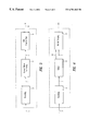
- FIG. 3 shows a device for converting a digital video signal into an analog video signal according to the invention
- FIG. 4 shows a device for providing generational copy control of a digital video signal according to the invention.
- FIG. 1 An example of the use of the pseudo-sync pulses according to the invention is described with reference to FIGS. 1 and 2.
- the pulses are located on lines 1 - 3 , 261 - 265 and 523 - 525 of an NTSC/525 analog video signal.
- the vertical blanking interval Y extends from line 523 to line 23 and line 261 to 286 .
- the numbers in FIG. 1 are according to NTSC standard line numbering, known to a person skilled in the art.
- the first line number of the active picture area is line 24 in the odd part of the picture area, shown in the upper part of FIG. 1 and line 287 in the even part of the picture area, shown in the bottom part of FIG. 1 .
- FIG. 1 the pulses are located on lines 1 - 3 , 261 - 265 and 523 - 525 of an NTSC/525 analog video signal.
- the vertical blanking interval Y extends from line 523 to line 23 and line 261 to 286 .
- the pulses are located on lines 307 - 312 and 620 - 625 of a PAL/625 video signal.
- the vertical blanking interval Y extends from line 307 to line 336 and line 620 to 24 .
- the numbers in FIG. 2 are according to PAL standard line numbering, known to a person skilled in the art.
- the first line number of the active picture area is line 337 in the odd part of the picture area, shown in the upper part of FIG. 2 and line 25 in the even part of the picture area, shown in the bottom part of FIG. 2 .
- pseudo-sync pulses located on the lines as shown in FIG. 1 or FIG. 2 .
- the pseudo-pulses can be located in the whole blanking interval. It must also be understood that the number of pseudo-sync pulses can vary.
- pseudo-sync pulses ordered pseudo-sync pulses as described in U.S. Pat. No. 4,631,603 can be used for instance.
- the latter document discloses a video signal modified so that a television receiver will provide a normal picture from the modified video signal while videotape recording of the modified video signal produces generally unacceptable pictures.
- anti-copy signals are present in the modified video signal. These anti-copy signals consist of ordered pseudo-sync pulses within a blanking interval of the signal. These pulses cause an automatic gain control in a videotape recorder to sense an erroneous indication of video signal level and produce a gain correction that results in an unacceptable videotape recording. It must be understood that not only the pulses as described in U.S. Pat.
- VBI signals could also be used as long as they have the properties described above. It must also be understood that not only the pulses in the VBI can be used. Also pulses in the HBI, horizontal blanking interval, can be used. Specifically, they must be part of the analog video signal, which will generally not be recorded faithfully on analog or digital recorders. This ensures that even non-compliant devices will remove the generational control signals.
- the invention is not restricted to video signals of the PAL or NTSC format, other formats can also be used, like e.g. SECAM.
- a small subset of the anti-copy protection signals as described in U.S. Pat. No. 4,631,603 can be used.
- a tag comprising of these anti-copy protection signals, is located in the vertical blanking area of the analog video in an area which is generally not properly recorded in a digital recorder.
- This tag produces no artifacts with VHS VCR's.
- This analog tag can for example be activated remotely in so-called set-top boxes (STB's) utilizing an encoder IC capable of producing these signals.
- Some systems providing a method for generational copy control use a control pattern situated in the active picture area.
- a chroma domain active picture area tag can be used.
- this tag must be removed to change the generational copy status of the material, e.g. from ‘Copy-Once’ to ‘Copy-No-More’.
- Other methods propose the addition of a second watermark to an original ‘Copy-Once’ watermark to designate a particular piece of video as ‘Copy-No-More’. Both of these methods have the disadvantage that in the compressed domain, such as MPEG, as a minimum, a partial MPEG de-code and re-encode are required. This has implications both on the cost and the potential video quality after performing this transform.
- Table 1 shows as an example different possible situations in case the watermark state is ‘No-Watermark’
- Table 2 shows as an example different possible situations in case the watermark state is ‘Copy-Once’
- Table 3 shows as an example different possible situations in case the watermark state is ‘Copy-Never’.
- watermarking is the marking of the content information present in the digital video signal.
- PPN 15391 PPN 15391
- the hidden video watermark indicates ‘No-Watermark’.
- copying is allowed irrespective of the status of the pseudo-sync pulses or the stability of the time base copying.
- the hidden video watermark indicates ‘Copy-Once’.
- copying is only allowed when the pseudo-sync pulses are detected as well as the time base of the video signal is stable.
- analog recorders e.g. VHS, Betamax, Hi8 etc.
- the hidden video watermark indicates ‘Copy-Never’.
- this Table can be seen that irrespective of the status of the pseudo-sync pulses or the stability of the time base copying is prohibited.
- FIG. 3 a device for converting a digital video signal into an analog video signal according to the invention is shown.
- the digital video signal can have different sources.
- the signal can for example be supplied from a set-top box, the set-top box having received the signal via a broadcasting connection. It can also become available by reading out a record carrier.
- the digital video signal 1 comprises of content information, first supplemental information and second supplemental information.
- the first supplemental information is represented by a watermark pattern
- the second supplemental information is represented by a control pattern.
- the digital video signal 1 is output from the means 2 for receiving the digital video signal and received in means 3 for converting the digital video signal into an analog video signal.
- the now analog video signal 4 is received in means 5 for adding pseudo-sync pulses.
- pseudo-sync pulses representing the second supplemental information are added to the blanking interval of the analog video signal.
- These pulses can for example be activated in so-called set-top boxes (STB's) utilizing an encoder IC capable of producing these signals.
- STB's set-top boxes
- FIG. 1 and FIG. 2 is shown on which positions these pulses can be located.
- the modified video signal 6 now comprising of content information, first supplemental information being represented by the status of the watermark pattern and second supplemental information represented by the status of the pseudo-sync pulses is outputted.
- FIG. 4 a device for providing generational copy control of a video signal according to the invention is shown.
- An analog video signal 7 for example the modified video signal 6 as described in FIG. 3, is received in means 8 for receiving an analog video signal.
- the analog video signal 7 comprises of content information, first supplemental information and second supplemental information.
- the analog video signal 7 is output from the means 8 for receiving the analog video signal and received in a detector 9 .
- This detector 9 the statuses of the first supplemental information, the second supplemental information and the stability of the time base of the analog video signal are detected.
- This status information 10 is output, together with the analog video signal to means 11 for permitting copying of the content information.
- This means 11 for permitting copying of the content information decides, for example by using Table 1, Table 2 or Table 3, whether copying of the content information must be allowed or prohibited. If copying of the content information is allowed the analog video signal is output.
- the first and second supplemental information must than be stored in the analog signal.
- the first supplemental information can be an analog watermark
- the second supplemental information can for example be a signal stored in the blanking interval indicating the use or non-use of the pseudo-sync pulses.
- the entrance signal of for example a STB can thus be a digital signal as well as an analog signal.
- a separate invention comprises copy control of a digital video signal.
- This digital video signal comprises content information and only one sort of supplemental information, namely the supplemental information represented by a control pattern. Permitting copying of the content information is now decided on the status of the supplemental information.
- Pseudo-sync pulses present in the blanking interval of the analog video signal now represent the second supplemental information.
- no second kind of supplemental information is used in order to perform copy control.
- turning off and on the adding of the pseudo-sync pulses can be used to create a low bit rate signal.
- a number present in this signal can be combined with a identification number provided by the user of the content information in order to gain permission to copy this content information. It must be understood that this separate invention can also be extended to generational copy control.
Abstract
Description
| TABLE 1 | ||||
| Watermark state: | ||||
| ‘No-Watermark’ | Time base stable | Time base unstable | ||
| Pseudo-sync pulses | Allow copy | Allow copy | ||
| present | ||||
| Pseudo-sync pulses | Allow copy | Allow copy | ||
| not present | ||||
| TABLE 2 | ||||
| Watermark state: | ||||
| ‘Copy-Once’ | Time base stable | Time base unstable | ||
| Pseudo-sync pulses | Allow copy | Prohibit copy | ||
| present | ||||
| Pseudo-sync pulses | Prohibit copy | Prohibit copy | ||
| not present | ||||
| TABLE 3 | ||||
| Watermark state: | ||||
| ‘Copy-Never’ | Time base stable | Time base unstable | ||
| Pseudo-sync pulses | Prohibit copy | Prohibit copy | ||
| present | ||||
| Pseudo-sync pulses | Prohibit copy | Prohibit copy | ||
| not present | ||||
Claims (17)
Priority Applications (1)
| Application Number | Priority Date | Filing Date | Title |
|---|---|---|---|
| US09/327,996 US6701062B1 (en) | 1998-06-06 | 1999-06-08 | Generational copy control of a video signal |
Applications Claiming Priority (2)
| Application Number | Priority Date | Filing Date | Title |
|---|---|---|---|
| US8868298P | 1998-06-06 | 1998-06-06 | |
| US09/327,996 US6701062B1 (en) | 1998-06-06 | 1999-06-08 | Generational copy control of a video signal |
Publications (1)
| Publication Number | Publication Date |
|---|---|
| US6701062B1 true US6701062B1 (en) | 2004-03-02 |
Family
ID=31890723
Family Applications (1)
| Application Number | Title | Priority Date | Filing Date |
|---|---|---|---|
| US09/327,996 Expired - Lifetime US6701062B1 (en) | 1998-06-06 | 1999-06-08 | Generational copy control of a video signal |
Country Status (1)
| Country | Link |
|---|---|
| US (1) | US6701062B1 (en) |
Cited By (21)
| Publication number | Priority date | Publication date | Assignee | Title |
|---|---|---|---|---|
| US20010053237A1 (en) * | 2000-06-07 | 2001-12-20 | Nec Corporation | Controlling a watermark strength embedded into a digital image |
| US20020061122A1 (en) * | 2000-10-26 | 2002-05-23 | Nec Corporation | Image data protection technique |
| US20020165983A1 (en) * | 2001-05-01 | 2002-11-07 | Diego Gastaldi | Method and apparatus for tagging media presentations with subscriber identification information |
| US20030007664A1 (en) * | 2001-07-05 | 2003-01-09 | Davis Bruce L. | Watermarking to set video usage permissions |
| US20030028882A1 (en) * | 2001-07-05 | 2003-02-06 | Davis Bruce L. | Watermarking and electronic program guides |
| US20030090698A1 (en) * | 2001-02-13 | 2003-05-15 | Maes Maurice Jerome Justin Jean-Baptiste | Processing copy protection signals |
| US20040161108A1 (en) * | 2003-02-14 | 2004-08-19 | Kabushiki Kaisha Toshiba | Watermark processing device and watermark processing method |
| US20050135614A1 (en) * | 1999-02-25 | 2005-06-23 | Hollar Mark A. | Method and apparatus for enhanced audio/video services with two watermarks |
| US20050195327A1 (en) * | 2003-08-26 | 2005-09-08 | Chupp Christopher E. | Method and system for enhanced modulation of video signals |
| US20060017747A1 (en) * | 2004-07-26 | 2006-01-26 | Dawson Thomas P | Copy protection arrangement |
| US20060093140A1 (en) * | 2004-10-28 | 2006-05-04 | Macrovision Corporation | Content management for high definition television |
| US7043138B1 (en) * | 1998-12-22 | 2006-05-09 | Sony Corporation | Broadcast receiver and system for performing copy prohibition and timed recording |
| US20060251252A1 (en) * | 2005-05-06 | 2006-11-09 | Macrovision Corporation | Method and apparatus for modifying a subsequently generated control command in a content control system |
| US20080309816A1 (en) * | 2007-06-15 | 2008-12-18 | Macrovision Corporation | Television content control system and method with cross-platform capability |
| US20090087110A1 (en) * | 2007-09-28 | 2009-04-02 | Dolby Laboratories Licensing Corporation | Multimedia coding and decoding with additional information capability |
| US20090141793A1 (en) * | 2007-11-29 | 2009-06-04 | Koplar Interactive Systems International, L.L.C. | Dual channel encoding and detection |
| US20090158318A1 (en) * | 2000-12-21 | 2009-06-18 | Levy Kenneth L | Media Methods and Systems |
| US7664175B1 (en) | 2004-06-16 | 2010-02-16 | Koplar Interactive Systems International, L.L.C. | Mark-based content modulation and detection |
| US20100199314A1 (en) * | 2001-07-05 | 2010-08-05 | Davis Bruce L | Methods employing stored preference data to identify video of interest to a consumer |
| US20100266041A1 (en) * | 2007-12-19 | 2010-10-21 | Walter Gish | Adaptive motion estimation |
| WO2011011854A1 (en) * | 2009-07-31 | 2011-02-03 | Bce Inc. | Controlling media conveyance at a customer receiver |
Citations (6)
| Publication number | Priority date | Publication date | Assignee | Title |
|---|---|---|---|---|
| US4631603A (en) * | 1985-04-17 | 1986-12-23 | Macrovision | Method and apparatus for processing a video signal so as to prohibit the making of acceptable video tape recordings thereof |
| US5579120A (en) * | 1993-10-08 | 1996-11-26 | Sony Corporation | Copyright protection for digital signal recording and/or reproduction and recording medium thereof |
| US5778064A (en) * | 1995-03-31 | 1998-07-07 | Sony Corporation | Apparatus and method for processing a high definition video signal |
| US6035094A (en) * | 1996-03-06 | 2000-03-07 | Sony Corporation | Video signal processing apparatus and method for securing a copy protection effect, an apparatus for recording/reproducing the processed video signal and a record medium therefor |
| US6131161A (en) * | 1995-10-04 | 2000-10-10 | U.S. Philips Corporation | Marking a digitally encoded video and/or audio signal |
| US6243139B1 (en) * | 1993-12-22 | 2001-06-05 | Canon Kabushiki Kaisha | Apparatus for block-encoding input image signals |
-
1999
- 1999-06-08 US US09/327,996 patent/US6701062B1/en not_active Expired - Lifetime
Patent Citations (6)
| Publication number | Priority date | Publication date | Assignee | Title |
|---|---|---|---|---|
| US4631603A (en) * | 1985-04-17 | 1986-12-23 | Macrovision | Method and apparatus for processing a video signal so as to prohibit the making of acceptable video tape recordings thereof |
| US5579120A (en) * | 1993-10-08 | 1996-11-26 | Sony Corporation | Copyright protection for digital signal recording and/or reproduction and recording medium thereof |
| US6243139B1 (en) * | 1993-12-22 | 2001-06-05 | Canon Kabushiki Kaisha | Apparatus for block-encoding input image signals |
| US5778064A (en) * | 1995-03-31 | 1998-07-07 | Sony Corporation | Apparatus and method for processing a high definition video signal |
| US6131161A (en) * | 1995-10-04 | 2000-10-10 | U.S. Philips Corporation | Marking a digitally encoded video and/or audio signal |
| US6035094A (en) * | 1996-03-06 | 2000-03-07 | Sony Corporation | Video signal processing apparatus and method for securing a copy protection effect, an apparatus for recording/reproducing the processed video signal and a record medium therefor |
Cited By (53)
| Publication number | Priority date | Publication date | Assignee | Title |
|---|---|---|---|---|
| US20060153529A1 (en) * | 1998-12-22 | 2006-07-13 | Sony Corporation | Broadcast receiver and system for performing copy prohibition and timed recording |
| US7043138B1 (en) * | 1998-12-22 | 2006-05-09 | Sony Corporation | Broadcast receiver and system for performing copy prohibition and timed recording |
| US7715689B2 (en) | 1998-12-22 | 2010-05-11 | Sony Corporation | Broadcast receiver and system for performing copy prohibition and timed recording |
| US20050135614A1 (en) * | 1999-02-25 | 2005-06-23 | Hollar Mark A. | Method and apparatus for enhanced audio/video services with two watermarks |
| US20060195696A1 (en) * | 1999-02-25 | 2006-08-31 | Macrovision Corporation | Method and apparatus for enhanced audio/video services with watermarks and associated data |
| US7027611B2 (en) * | 2000-06-07 | 2006-04-11 | Nec Corporation | Controlling a watermark strength embedded into a digital image |
| US20010053237A1 (en) * | 2000-06-07 | 2001-12-20 | Nec Corporation | Controlling a watermark strength embedded into a digital image |
| US20020061122A1 (en) * | 2000-10-26 | 2002-05-23 | Nec Corporation | Image data protection technique |
| US7050604B2 (en) * | 2000-10-26 | 2006-05-23 | Nec Corporation | Image data protection technique |
| US8825518B2 (en) | 2000-12-21 | 2014-09-02 | Digimarc Corporation | Media methods and systems |
| US20090158318A1 (en) * | 2000-12-21 | 2009-06-18 | Levy Kenneth L | Media Methods and Systems |
| US7310819B2 (en) * | 2001-02-13 | 2007-12-18 | Koninklijke Philips Electronics N.V. | Processing copy protection signals |
| US20030090698A1 (en) * | 2001-02-13 | 2003-05-15 | Maes Maurice Jerome Justin Jean-Baptiste | Processing copy protection signals |
| US7158185B2 (en) * | 2001-05-01 | 2007-01-02 | Scientific-Atlanta, Inc. | Method and apparatus for tagging media presentations with subscriber identification information |
| US20020165983A1 (en) * | 2001-05-01 | 2002-11-07 | Diego Gastaldi | Method and apparatus for tagging media presentations with subscriber identification information |
| US8036421B2 (en) | 2001-07-05 | 2011-10-11 | Digimarc Corporation | Methods employing topical subject criteria in video processing |
| US8122465B2 (en) * | 2001-07-05 | 2012-02-21 | Digimarc Corporation | Watermarking to set video usage permissions |
| US20030028882A1 (en) * | 2001-07-05 | 2003-02-06 | Davis Bruce L. | Watermarking and electronic program guides |
| US8085979B2 (en) | 2001-07-05 | 2011-12-27 | Digimarc Corporation | Methods employing stored preference data to identify video of interest to a consumer |
| US20100199314A1 (en) * | 2001-07-05 | 2010-08-05 | Davis Bruce L | Methods employing stored preference data to identify video of interest to a consumer |
| US8032909B2 (en) | 2001-07-05 | 2011-10-04 | Digimarc Corporation | Watermarking and electronic program guides |
| US20030007664A1 (en) * | 2001-07-05 | 2003-01-09 | Davis Bruce L. | Watermarking to set video usage permissions |
| US20040161108A1 (en) * | 2003-02-14 | 2004-08-19 | Kabushiki Kaisha Toshiba | Watermark processing device and watermark processing method |
| US20050195327A1 (en) * | 2003-08-26 | 2005-09-08 | Chupp Christopher E. | Method and system for enhanced modulation of video signals |
| US7692723B2 (en) | 2003-08-26 | 2010-04-06 | Koplar Interactive Systems International L.L.C. | Method and system for enhanced modulation of video signals |
| US20080056351A1 (en) * | 2003-08-26 | 2008-03-06 | Koplar Interactive Systems International, L.L.C. | Method and system for enhanced modulation of video signals |
| US8405772B2 (en) | 2003-08-26 | 2013-03-26 | Koplar Interactive Systems International L.L.C. | Method and system for enhanced modulation of video signals |
| US7586541B2 (en) | 2003-08-26 | 2009-09-08 | Koplar Interactive Systems International, L.L.C. | Method and system for enhanced modulation of video signals |
| US20100141836A1 (en) * | 2003-08-26 | 2010-06-10 | Koplar Interactive Systems International, Llc | Method and system for enhanced modulation of video signals |
| US20100166083A1 (en) * | 2004-06-16 | 2010-07-01 | Chupp Christopher E | Mark-based content modulation and detection |
| US7664175B1 (en) | 2004-06-16 | 2010-02-16 | Koplar Interactive Systems International, L.L.C. | Mark-based content modulation and detection |
| US8842725B2 (en) | 2004-06-16 | 2014-09-23 | Koplar Interactive Systems International L.L.C. | Mark-based content modulation and detection |
| US7703113B2 (en) | 2004-07-26 | 2010-04-20 | Sony Corporation | Copy protection arrangement |
| US20060017747A1 (en) * | 2004-07-26 | 2006-01-26 | Dawson Thomas P | Copy protection arrangement |
| US20070277197A1 (en) * | 2004-07-26 | 2007-11-29 | Dawson Thomas P | Copy protection arrangement |
| US7319469B2 (en) | 2004-07-26 | 2008-01-15 | Sony Corporation | Copy protection arrangement |
| US20060093140A1 (en) * | 2004-10-28 | 2006-05-04 | Macrovision Corporation | Content management for high definition television |
| US8355621B2 (en) | 2004-10-28 | 2013-01-15 | Rovi Solutions Corporation | Content management for a video signal |
| US20060093139A1 (en) * | 2004-10-28 | 2006-05-04 | Macrovision Corporation | Defeat method and apparatus for content management for high definition television |
| US20100290620A1 (en) * | 2005-05-06 | 2010-11-18 | Ronald Quan | Method and apparatus for modifying a subsequently generated control command in a content control system |
| US8374347B2 (en) | 2005-05-06 | 2013-02-12 | Rovi Solutions Corporation | Method and apparatus for modifying a subsequently generated control command in a content control system |
| US7792293B2 (en) | 2005-05-06 | 2010-09-07 | Rovi Solutions Corporation | Method and apparatus for modifying a subsequently generated control command in a content control system |
| US20060251252A1 (en) * | 2005-05-06 | 2006-11-09 | Macrovision Corporation | Method and apparatus for modifying a subsequently generated control command in a content control system |
| US20080309816A1 (en) * | 2007-06-15 | 2008-12-18 | Macrovision Corporation | Television content control system and method with cross-platform capability |
| US8229159B2 (en) | 2007-09-28 | 2012-07-24 | Dolby Laboratories Licensing Corporation | Multimedia coding and decoding with additional information capability |
| US8571256B2 (en) | 2007-09-28 | 2013-10-29 | Dolby Laboratories Licensing Corporation | Multimedia coding and decoding with additional information capability |
| US20090087110A1 (en) * | 2007-09-28 | 2009-04-02 | Dolby Laboratories Licensing Corporation | Multimedia coding and decoding with additional information capability |
| US8798133B2 (en) | 2007-11-29 | 2014-08-05 | Koplar Interactive Systems International L.L.C. | Dual channel encoding and detection |
| US20090141793A1 (en) * | 2007-11-29 | 2009-06-04 | Koplar Interactive Systems International, L.L.C. | Dual channel encoding and detection |
| US20100266041A1 (en) * | 2007-12-19 | 2010-10-21 | Walter Gish | Adaptive motion estimation |
| US8457208B2 (en) | 2007-12-19 | 2013-06-04 | Dolby Laboratories Licensing Corporation | Adaptive motion estimation |
| WO2011011854A1 (en) * | 2009-07-31 | 2011-02-03 | Bce Inc. | Controlling media conveyance at a customer receiver |
| US9641889B2 (en) | 2009-07-31 | 2017-05-02 | Bce Inc. | Method and system for controlling media conveyance by a device to a user based on current location of the device |
Similar Documents
| Publication | Publication Date | Title |
|---|---|---|
| US6701062B1 (en) | Generational copy control of a video signal | |
| KR100398913B1 (en) | An apparatus and a method for reproducing a picture information | |
| US6473560B1 (en) | Copy protection schemes for copy protected digital material | |
| US5315448A (en) | Copy protection for hybrid digital video tape recording and unprotected source material | |
| US7720224B2 (en) | System and method for the assertion and identification of rights information in an analog video signal | |
| EP1155569B1 (en) | Controlling copying of a video signal employing a watermark and associated data | |
| JP3114263B2 (en) | Video signal recording system | |
| US8254470B2 (en) | Encoding and decoding of embedded data stream in analog video using copy protection pulses | |
| US6819765B1 (en) | Video-signal output apparatus, video-signal input apparatus, and scramble method, and descramble method | |
| WO1999065240A1 (en) | Generational copy control of a digital video signal | |
| GB2387497A (en) | Anti-copy protection for a video signal | |
| JP3381165B2 (en) | Video signal transmission method, video signal recording method, video signal reproduction method, video signal recording device, and video signal reproduction device | |
| KR100636781B1 (en) | Digital recording device for detecting copy prevent signal and method thereof | |
| JP3381164B2 (en) | Video signal transmission method, video signal recording method, video signal reproduction method, video signal recording device, and video signal reproduction device | |
| JP3570403B2 (en) | Video signal recording method and video signal recording device | |
| RU2195084C2 (en) | " water-mark "method and single-copying device for video recording | |
| JP3570402B2 (en) | Video signal processing method, video signal reproduction method, video signal processing device, and video signal reproduction device | |
| NZ328701A (en) | Analog copy protection of video signal | |
| JPH06296258A (en) | Non-level standard signal adding device and high vision signal |
Legal Events
| Date | Code | Title | Description |
|---|---|---|---|
| AS | Assignment |
Owner name: MACROVISION CORPORATION, CALIFORNIA Free format text: ASSIGNMENT OF ASSIGNORS INTEREST;ASSIGNORS:TALSTRA, JOHAN CORNELIS;HOLLAR, MARK;KUROWSKI, KORDIAN;AND OTHERS;REEL/FRAME:010026/0137;SIGNING DATES FROM 19990525 TO 19990601 |
|
| STCF | Information on status: patent grant |
Free format text: PATENTED CASE |
|
| FPAY | Fee payment |
Year of fee payment: 4 |
|
| AS | Assignment |
Owner name: JPMORGAN CHASE BANK, N.A., NEW YORK Free format text: SECURITY AGREEMENT;ASSIGNORS:APTIV DIGITAL, INC.;GEMSTAR DEVELOPMENT CORPORATION;GEMSTAR-TV GUIDE INTERNATIONAL, INC.;AND OTHERS;REEL/FRAME:020986/0074 Effective date: 20080502 Owner name: JPMORGAN CHASE BANK, N.A.,NEW YORK Free format text: SECURITY AGREEMENT;ASSIGNORS:APTIV DIGITAL, INC.;GEMSTAR DEVELOPMENT CORPORATION;GEMSTAR-TV GUIDE INTERNATIONAL, INC.;AND OTHERS;REEL/FRAME:020986/0074 Effective date: 20080502 |
|
| AS | Assignment |
Owner name: ODS PROPERTIES, INC., CALIFORNIA Free format text: RELEASE BY SECURED PARTY;ASSIGNOR:JPMORGAN CHASE BANK, N.A. (A NATIONAL ASSOCIATION);REEL/FRAME:025222/0731 Effective date: 20100317 Owner name: ROVI GUIDES, INC. (FORMERLY KNOWN AS GEMSTAR-TV GU Free format text: RELEASE BY SECURED PARTY;ASSIGNOR:JPMORGAN CHASE BANK, N.A. (A NATIONAL ASSOCIATION);REEL/FRAME:025222/0731 Effective date: 20100317 Owner name: GEMSTAR DEVELOPMENT CORPORATION, CALIFORNIA Free format text: RELEASE BY SECURED PARTY;ASSIGNOR:JPMORGAN CHASE BANK, N.A. (A NATIONAL ASSOCIATION);REEL/FRAME:025222/0731 Effective date: 20100317 Owner name: TV GUIDE ONLINE, LLC, CALIFORNIA Free format text: RELEASE BY SECURED PARTY;ASSIGNOR:JPMORGAN CHASE BANK, N.A. (A NATIONAL ASSOCIATION);REEL/FRAME:025222/0731 Effective date: 20100317 Owner name: ALL MEDIA GUIDE, LLC, CALIFORNIA Free format text: RELEASE BY SECURED PARTY;ASSIGNOR:JPMORGAN CHASE BANK, N.A. (A NATIONAL ASSOCIATION);REEL/FRAME:025222/0731 Effective date: 20100317 Owner name: ROVI SOLUTIONS LIMITED (FORMERLY KNOWN AS MACROVIS Free format text: RELEASE BY SECURED PARTY;ASSIGNOR:JPMORGAN CHASE BANK, N.A. (A NATIONAL ASSOCIATION);REEL/FRAME:025222/0731 Effective date: 20100317 Owner name: ROVI DATA SOLUTIONS, INC. (FORMERLY KNOWN AS TV GU Free format text: RELEASE BY SECURED PARTY;ASSIGNOR:JPMORGAN CHASE BANK, N.A. (A NATIONAL ASSOCIATION);REEL/FRAME:025222/0731 Effective date: 20100317 Owner name: INDEX SYSTEMS INC., CALIFORNIA Free format text: RELEASE BY SECURED PARTY;ASSIGNOR:JPMORGAN CHASE BANK, N.A. (A NATIONAL ASSOCIATION);REEL/FRAME:025222/0731 Effective date: 20100317 Owner name: STARSIGHT TELECAST, INC., CALIFORNIA Free format text: RELEASE BY SECURED PARTY;ASSIGNOR:JPMORGAN CHASE BANK, N.A. (A NATIONAL ASSOCIATION);REEL/FRAME:025222/0731 Effective date: 20100317 Owner name: TV GUIDE, INC., CALIFORNIA Free format text: RELEASE BY SECURED PARTY;ASSIGNOR:JPMORGAN CHASE BANK, N.A. (A NATIONAL ASSOCIATION);REEL/FRAME:025222/0731 Effective date: 20100317 Owner name: APTIV DIGITAL, INC., CALIFORNIA Free format text: RELEASE BY SECURED PARTY;ASSIGNOR:JPMORGAN CHASE BANK, N.A. (A NATIONAL ASSOCIATION);REEL/FRAME:025222/0731 Effective date: 20100317 Owner name: ROVI SOLUTIONS CORPORATION (FORMERLY KNOWN AS MACR Free format text: RELEASE BY SECURED PARTY;ASSIGNOR:JPMORGAN CHASE BANK, N.A. (A NATIONAL ASSOCIATION);REEL/FRAME:025222/0731 Effective date: 20100317 Owner name: UNITED VIDEO PROPERTIES, INC., CALIFORNIA Free format text: RELEASE BY SECURED PARTY;ASSIGNOR:JPMORGAN CHASE BANK, N.A. (A NATIONAL ASSOCIATION);REEL/FRAME:025222/0731 Effective date: 20100317 Owner name: ROVI TECHNOLOGIES CORPORATION, CALIFORNIA Free format text: RELEASE BY SECURED PARTY;ASSIGNOR:JPMORGAN CHASE BANK, N.A. (A NATIONAL ASSOCIATION);REEL/FRAME:025222/0731 Effective date: 20100317 |
|
| FPAY | Fee payment |
Year of fee payment: 8 |
|
| AS | Assignment |
Owner name: JPMORGAN CHASE BANK, N.A., AS COLLATERAL AGENT, NE Free format text: SECURITY INTEREST;ASSIGNORS:APTIV DIGITAL, INC., A DELAWARE CORPORATION;GEMSTAR DEVELOPMENT CORPORATION, A CALIFORNIA CORPORATION;INDEX SYSTEMS INC, A BRITISH VIRGIN ISLANDS COMPANY;AND OTHERS;REEL/FRAME:027039/0168 Effective date: 20110913 |
|
| AS | Assignment |
Owner name: MORGAN STANLEY SENIOR FUNDING, INC., AS COLLATERAL AGENT, MARYLAND Free format text: PATENT SECURITY AGREEMENT;ASSIGNORS:APTIV DIGITAL, INC.;GEMSTAR DEVELOPMENT CORPORATION;INDEX SYSTEMS INC.;AND OTHERS;REEL/FRAME:033407/0035 Effective date: 20140702 Owner name: ROVI TECHNOLOGIES CORPORATION, CALIFORNIA Free format text: PATENT RELEASE;ASSIGNOR:JPMORGAN CHASE BANK, N.A., AS COLLATERAL AGENT;REEL/FRAME:033396/0001 Effective date: 20140702 Owner name: TV GUIDE INTERNATIONAL, INC., CALIFORNIA Free format text: PATENT RELEASE;ASSIGNOR:JPMORGAN CHASE BANK, N.A., AS COLLATERAL AGENT;REEL/FRAME:033396/0001 Effective date: 20140702 Owner name: INDEX SYSTEMS INC., CALIFORNIA Free format text: PATENT RELEASE;ASSIGNOR:JPMORGAN CHASE BANK, N.A., AS COLLATERAL AGENT;REEL/FRAME:033396/0001 Effective date: 20140702 Owner name: ROVI CORPORATION, CALIFORNIA Free format text: PATENT RELEASE;ASSIGNOR:JPMORGAN CHASE BANK, N.A., AS COLLATERAL AGENT;REEL/FRAME:033396/0001 Effective date: 20140702 Owner name: ALL MEDIA GUIDE, LLC, CALIFORNIA Free format text: PATENT RELEASE;ASSIGNOR:JPMORGAN CHASE BANK, N.A., AS COLLATERAL AGENT;REEL/FRAME:033396/0001 Effective date: 20140702 Owner name: MORGAN STANLEY SENIOR FUNDING, INC., AS COLLATERAL Free format text: PATENT SECURITY AGREEMENT;ASSIGNORS:APTIV DIGITAL, INC.;GEMSTAR DEVELOPMENT CORPORATION;INDEX SYSTEMS INC.;AND OTHERS;REEL/FRAME:033407/0035 Effective date: 20140702 Owner name: UNITED VIDEO PROPERTIES, INC., CALIFORNIA Free format text: PATENT RELEASE;ASSIGNOR:JPMORGAN CHASE BANK, N.A., AS COLLATERAL AGENT;REEL/FRAME:033396/0001 Effective date: 20140702 Owner name: GEMSTAR DEVELOPMENT CORPORATION, CALIFORNIA Free format text: PATENT RELEASE;ASSIGNOR:JPMORGAN CHASE BANK, N.A., AS COLLATERAL AGENT;REEL/FRAME:033396/0001 Effective date: 20140702 Owner name: ROVI GUIDES, INC., CALIFORNIA Free format text: PATENT RELEASE;ASSIGNOR:JPMORGAN CHASE BANK, N.A., AS COLLATERAL AGENT;REEL/FRAME:033396/0001 Effective date: 20140702 Owner name: ROVI SOLUTIONS CORPORATION, CALIFORNIA Free format text: PATENT RELEASE;ASSIGNOR:JPMORGAN CHASE BANK, N.A., AS COLLATERAL AGENT;REEL/FRAME:033396/0001 Effective date: 20140702 Owner name: APTIV DIGITAL, INC., CALIFORNIA Free format text: PATENT RELEASE;ASSIGNOR:JPMORGAN CHASE BANK, N.A., AS COLLATERAL AGENT;REEL/FRAME:033396/0001 Effective date: 20140702 Owner name: STARSIGHT TELECAST, INC., CALIFORNIA Free format text: PATENT RELEASE;ASSIGNOR:JPMORGAN CHASE BANK, N.A., AS COLLATERAL AGENT;REEL/FRAME:033396/0001 Effective date: 20140702 |
|
| FPAY | Fee payment |
Year of fee payment: 12 |
|
| AS | Assignment |
Owner name: ROVI SOLUTIONS CORPORATION, CALIFORNIA Free format text: CHANGE OF NAME;ASSIGNOR:MACROVISION CORPORATION;REEL/FRAME:038947/0271 Effective date: 20091001 |
|
| AS | Assignment |
Owner name: ROVI SOLUTIONS CORPORATION, CALIFORNIA Free format text: SECURITY INTEREST;ASSIGNOR:MARKING OBJECT VIRTUALIZATION INTELLIGENCE, LLC;REEL/FRAME:039261/0298 Effective date: 20160627 |
|
| AS | Assignment |
Owner name: ROVI SOLUTIONS CORPORATION, CALIFORNIA Free format text: CORRECTIVE ASSIGNMENT TO CORRECT THE EXECUTION DATE TO READ JULY 22, 2016 PREVIOUSLY RECORDED ON REEL 039261 FRAME 0298. ASSIGNOR(S) HEREBY CONFIRMS THE EXECUTION DATE OF THE SECURITY INTEREST;ASSIGNOR:MARKING OBJECT VIRTUALIZATION INTELLIGENCE, LLC;REEL/FRAME:039503/0398 Effective date: 20160722 |
|
| AS | Assignment |
Owner name: MARKING OBJECT VIRTUALIZATION INTELLIGENCE, LLC, T Free format text: ASSIGNMENT OF ASSIGNORS INTEREST;ASSIGNOR:ROVI SOLUTIONS CORPORATION;REEL/FRAME:039426/0931 Effective date: 20160630 |
|
| AS | Assignment |
Owner name: MARKING OBJECT VIRTUALIZATION INTELLIGENCE LLC, TE Free format text: RELEASE BY SECURED PARTY;ASSIGNOR:ROVI SOLUTIONS CORPORATION;REEL/FRAME:040866/0949 Effective date: 20161229 |
|
| AS | Assignment |
Owner name: ROVI GUIDES, INC., CALIFORNIA Free format text: RELEASE OF SECURITY INTEREST IN PATENT RIGHTS;ASSIGNOR:MORGAN STANLEY SENIOR FUNDING, INC., AS COLLATERAL AGENT;REEL/FRAME:051145/0090 Effective date: 20191122 Owner name: INDEX SYSTEMS INC., CALIFORNIA Free format text: RELEASE OF SECURITY INTEREST IN PATENT RIGHTS;ASSIGNOR:MORGAN STANLEY SENIOR FUNDING, INC., AS COLLATERAL AGENT;REEL/FRAME:051145/0090 Effective date: 20191122 Owner name: UNITED VIDEO PROPERTIES, INC., CALIFORNIA Free format text: RELEASE OF SECURITY INTEREST IN PATENT RIGHTS;ASSIGNOR:MORGAN STANLEY SENIOR FUNDING, INC., AS COLLATERAL AGENT;REEL/FRAME:051145/0090 Effective date: 20191122 Owner name: VEVEO, INC., CALIFORNIA Free format text: RELEASE OF SECURITY INTEREST IN PATENT RIGHTS;ASSIGNOR:MORGAN STANLEY SENIOR FUNDING, INC., AS COLLATERAL AGENT;REEL/FRAME:051145/0090 Effective date: 20191122 Owner name: STARSIGHT TELECAST, INC., CALIFORNIA Free format text: RELEASE OF SECURITY INTEREST IN PATENT RIGHTS;ASSIGNOR:MORGAN STANLEY SENIOR FUNDING, INC., AS COLLATERAL AGENT;REEL/FRAME:051145/0090 Effective date: 20191122 Owner name: APTIV DIGITAL INC., CALIFORNIA Free format text: RELEASE OF SECURITY INTEREST IN PATENT RIGHTS;ASSIGNOR:MORGAN STANLEY SENIOR FUNDING, INC., AS COLLATERAL AGENT;REEL/FRAME:051145/0090 Effective date: 20191122 Owner name: ROVI TECHNOLOGIES CORPORATION, CALIFORNIA Free format text: RELEASE OF SECURITY INTEREST IN PATENT RIGHTS;ASSIGNOR:MORGAN STANLEY SENIOR FUNDING, INC., AS COLLATERAL AGENT;REEL/FRAME:051145/0090 Effective date: 20191122 Owner name: ROVI SOLUTIONS CORPORATION, CALIFORNIA Free format text: RELEASE OF SECURITY INTEREST IN PATENT RIGHTS;ASSIGNOR:MORGAN STANLEY SENIOR FUNDING, INC., AS COLLATERAL AGENT;REEL/FRAME:051145/0090 Effective date: 20191122 Owner name: SONIC SOLUTIONS LLC, CALIFORNIA Free format text: RELEASE OF SECURITY INTEREST IN PATENT RIGHTS;ASSIGNOR:MORGAN STANLEY SENIOR FUNDING, INC., AS COLLATERAL AGENT;REEL/FRAME:051145/0090 Effective date: 20191122 Owner name: GEMSTAR DEVELOPMENT CORPORATION, CALIFORNIA Free format text: RELEASE OF SECURITY INTEREST IN PATENT RIGHTS;ASSIGNOR:MORGAN STANLEY SENIOR FUNDING, INC., AS COLLATERAL AGENT;REEL/FRAME:051145/0090 Effective date: 20191122 |