US6679463B1 - Support with multi-stage clamping mechanism - Google Patents
Support with multi-stage clamping mechanism Download PDFInfo
- Publication number
- US6679463B1 US6679463B1 US10/458,248 US45824803A US6679463B1 US 6679463 B1 US6679463 B1 US 6679463B1 US 45824803 A US45824803 A US 45824803A US 6679463 B1 US6679463 B1 US 6679463B1
- Authority
- US
- United States
- Prior art keywords
- support
- clamp
- fixing unit
- primary
- clamping
- Prior art date
- Legal status (The legal status is an assumption and is not a legal conclusion. Google has not performed a legal analysis and makes no representation as to the accuracy of the status listed.)
- Expired - Fee Related
Links
Images


Classifications
-
- F—MECHANICAL ENGINEERING; LIGHTING; HEATING; WEAPONS; BLASTING
- F16—ENGINEERING ELEMENTS AND UNITS; GENERAL MEASURES FOR PRODUCING AND MAINTAINING EFFECTIVE FUNCTIONING OF MACHINES OR INSTALLATIONS; THERMAL INSULATION IN GENERAL
- F16M—FRAMES, CASINGS OR BEDS OF ENGINES, MACHINES OR APPARATUS, NOT SPECIFIC TO ENGINES, MACHINES OR APPARATUS PROVIDED FOR ELSEWHERE; STANDS; SUPPORTS
- F16M13/00—Other supports for positioning apparatus or articles; Means for steadying hand-held apparatus or articles
- F16M13/02—Other supports for positioning apparatus or articles; Means for steadying hand-held apparatus or articles for supporting on, or attaching to, an object, e.g. tree, gate, window-frame, cycle
- F16M13/022—Other supports for positioning apparatus or articles; Means for steadying hand-held apparatus or articles for supporting on, or attaching to, an object, e.g. tree, gate, window-frame, cycle repositionable
-
- F—MECHANICAL ENGINEERING; LIGHTING; HEATING; WEAPONS; BLASTING
- F16—ENGINEERING ELEMENTS AND UNITS; GENERAL MEASURES FOR PRODUCING AND MAINTAINING EFFECTIVE FUNCTIONING OF MACHINES OR INSTALLATIONS; THERMAL INSULATION IN GENERAL
- F16M—FRAMES, CASINGS OR BEDS OF ENGINES, MACHINES OR APPARATUS, NOT SPECIFIC TO ENGINES, MACHINES OR APPARATUS PROVIDED FOR ELSEWHERE; STANDS; SUPPORTS
- F16M13/00—Other supports for positioning apparatus or articles; Means for steadying hand-held apparatus or articles
-
- Y—GENERAL TAGGING OF NEW TECHNOLOGICAL DEVELOPMENTS; GENERAL TAGGING OF CROSS-SECTIONAL TECHNOLOGIES SPANNING OVER SEVERAL SECTIONS OF THE IPC; TECHNICAL SUBJECTS COVERED BY FORMER USPC CROSS-REFERENCE ART COLLECTIONS [XRACs] AND DIGESTS
- Y10—TECHNICAL SUBJECTS COVERED BY FORMER USPC
- Y10S—TECHNICAL SUBJECTS COVERED BY FORMER USPC CROSS-REFERENCE ART COLLECTIONS [XRACs] AND DIGESTS
- Y10S248/00—Supports
- Y10S248/917—Video display screen support
- Y10S248/918—Ancillary device support associated with a video display screen
Definitions
- the present invention relates to a clamping support for a portable electrical device such as an image capture device, and particularly to a support having a multi-stage clamping mechanism, which provides either a non-clamping free-standing support function, or a clamping function.
- a classical image-capturing device has at least a lens and a support located thereunder, where the support can be placed either on a desktop, a CRT type display, or any suitable plane surface. Regarding the distance and height in capturing a proper image, the most common position to put the image-capturing devices is around the top of the display. However, the LCD type display, which is much thinner than that of a CRT, requires a clamping mechanism to support the whole image-capturing device.
- the support 202 includes a main body 208 , a sliding portion 210 , a pair of springs 214 , and a lead board 212 .
- the sliding portion 210 can be combined with the main body 208 using the springs 214 located at each side of the main body 208 such that the support can clamp an object between the main body 208 and the sliding portion 210 .
- the lead board 212 can increase the weight of the sliding portion 210 to stabilize the support 202 in use.
- Various defects can still be found as below:
- the support 202 is not suitable for carrying.
- the springs 214 must be strong enough to give a stable clamping force in order to clamp an object firmly.
- the distance of travel for the sliding portion 210 under the main body 208 is quite long, which will easily result in jamming.
- the support device includes a neck 12 for connecting a camera 10 , a main arm 14 , a right arm 20 , and a left arm 20 ′.
- the arms 20 and 20 ′ can be rotated pivotally relative to the neck 12 .
- the main arm 14 has an end 21
- each of the right arm 20 and left arm 20 ′ has a hook 29 , 29 ′.
- the arms 20 and 20 ′ can be rotated forwardly to clamp an object (LCD display) 76 between the arms 20 , 20 ′ and the main arm 14 .
- the disadvantages of the support device is as following,
- the hooks 29 and 29 ′ are clamped at the front surface of the display 76 and might scratch the precious LCD panel when the support is moved carelessly.
- the way of attaching the display 76 basically is a rotate-to-clamp motion in an opposite direction for main arm 14 and arms 20 , 20 ′. Therefore the thickness of the display 76 has to be carefully limited in a certain range, or the support device will not clamp the object 76 tightly enough.
- the primary object of the present invention is to provide a stable, small size, and adjustable support with a multi-stage clamping mechanism, which provides not only a clamping but also a standing function.
- FIG. 1 is a perspective view of a prior art support for an image-capture device.
- FIG. 2A is a perspective view of another prior art support.
- FIG. 2B is a lateral view of the support of FIG. 2A in a clamping state.
- FIG. 3A is a front view of a support constructed in accordance with the principle of the present invention.
- FIG. 3B is a lateral view of the support of FIG. 3 A.
- FIG. 3C is a rear view of the support of FIG. 3 A.
- FIG. 3D is a bottom view of the support of FIG. 3 A.
- FIG. 4A is a view of the present invention in a clamping state.
- FIG. 4B is another view of the present invention in a clamping state.
- FIG. 4C is an exploded view of the fixing and moving portions of support of the present invention.
- FIG. 4D is a lateral view of the support of the present invention when clamping an object.
- FIG. 5A shows the support of the present invention in a standing state.
- FIG. 5B is another lateral view of the support of the present invention when clamping an object.
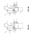
- FIGS. 6A and 6B are other lateral views when clamping an object.
- the present invention relates to a support 30 , which includes a fixing unit 31 , a moving unit 32 , a primary clamp 33 , and an auxiliary clamp 34 .
- the fixing unit 31 couples to an image-capturing device 311 , for example, a PC camera, digital camera . . . etc.
- a cable 312 connected to the image-capturing device 311 is fixed by a fastener 318 for to prevent the cable 312 from being randomly disposed.
- the cable 312 has a connector that meets USB (universal serial bus) or IEEE (institute of electrical and electronic engineers) specifications so as to enable further connection to a computer system or the like.
- the moving unit 32 is located at the rear portion of the fixing unit 31 , and the primary clamp 33 and the auxiliary clamp 34 are pivotally connected to the moving unit 32 via a shaft 35 , such that the moving unit 32 and the primary clamp 33 constantly and closely contact the fixing unit 31 .
- FIG. 4 A ⁇ FIG. 4D showing the structure for connecting the fixing unit 31 , moving unit 32 , primary clamp 33 and the auxiliary clamp 34 .
- the moving unit 32 is located at the rear portion of the fixing unit 31 , and a pair of columns 313 of the fixing unit 31 extend toward the moving unit 32 .
- Each of the columns 313 is fitted with a spring 314 that can be contained within a groove 321 together.
- a positioning block 315 , 316 is respectively located at each end of the spring 314 so as to firmly fix the column 313 and spring 314 within the groove 321 . Therefore, the moving unit 32 can be forcedly slid away from the fixing unit 31 along the column 313 .
- an extension plate 317 of the fixing unit 31 loosely penetrates a containing portion 322 . Please see FIG. 4 D.
- the moving unit 32 including the primary clamp 33 and the auxiliary clamp 34 can be pulled out away from the fixing unit 31 a distance D 1 for clamping an object 40 between the fixing unit 31 and the primary clamp 33 . Therefore, the image-capturing device 311 can be firmly supported above the object 40 in situations where the object 40 is an LCD display of a notebook computer or other thinner type display.
- the primary clamp 33 has an opening 331 for accommodating the auxiliary clamp 34 therein.
- the primary clamp 33 and the auxiliary clamp 34 have a generally L shape and are pivotally connected to the rear portion of the moving unit 32 . As a result, the clamp 33 and 34 can be folded under the extension plate 317 for allowing the standing mode of the support 30 on a plane surface, shown in FIG. 5 A.
- the primary clamp 33 and the auxiliary clamp 34 can be turned out together to allow a distance D 2 for clamping an object 50 that is thicker than the object 40 between the fixing unit 31 and the primary clamp 33 and, as shown in FIG. 5B, the primary clamp 33 can be turned out individually to allow a distance D 3 for clamping a thickness smaller than D 2 , between the fixing unit 31 and the auxiliary clamp 34 .
- the primary clamp 33 and the auxiliary clamp 34 can be turned out together to allow a distance D 4 for clamping a thicker object 70 , such as a desk-top LCD display between the fixing unit 31 and the primary clamp 33 or, as shown in FIG. 6B the primary clamp 33 can be turned out individually to allow a distance D 5 for clamping another thinner LCD display between the fixing unit 31 and the auxiliary clamp 34 .
Abstract
A stable, small size, and ajustable support with a multi-stage clamping mechanism that not only provides a clamping function but also a free-standing function and includes a fixing unit and a moving unit to define a first clamping distance via a resilient element. The primary clamp can be rotated individually, or the primary claim and the auxiliary clamp can be rotated together, so as to further provide a second or third clamping distance.
Description
The present invention relates to a clamping support for a portable electrical device such as an image capture device, and particularly to a support having a multi-stage clamping mechanism, which provides either a non-clamping free-standing support function, or a clamping function.
With the progress of image processing and data transmitting technologies, image capturing devices are getting more and more popular than ever. A classical image-capturing device has at least a lens and a support located thereunder, where the support can be placed either on a desktop, a CRT type display, or any suitable plane surface. Regarding the distance and height in capturing a proper image, the most common position to put the image-capturing devices is around the top of the display. However, the LCD type display, which is much thinner than that of a CRT, requires a clamping mechanism to support the whole image-capturing device.
Please see FIG. 1, taken from a disclosure published in the Taiwan IPO gazette as TW491527, showing a support for an image-capturing device. The support 202 includes a main body 208, a sliding portion 210, a pair of springs 214, and a lead board 212. The sliding portion 210 can be combined with the main body 208 using the springs 214 located at each side of the main body 208 such that the support can clamp an object between the main body 208 and the sliding portion 210. Furthermore, the lead board 212 can increase the weight of the sliding portion 210 to stabilize the support 202 in use. Various defects can still be found as below:
1. Due to the additional weight of the lead board 212, the support 202 is not suitable for carrying.
2. A square and huge body will lead to a wasting of limited space on a working surface.
3. Because of the extra weight of the lead board 212 attached to the sliding portion 210, the springs 214 must be strong enough to give a stable clamping force in order to clamp an object firmly.
4. The distance of travel for the sliding portion 210 under the main body 208 is quite long, which will easily result in jamming.
Another support device can also be found in U.S. Pat. No. 6,431,507. Please see FIGS. 2A and 2B. The support device includes a neck 12 for connecting a camera 10, a main arm 14, a right arm 20, and a left arm 20′. The arms 20 and 20′ can be rotated pivotally relative to the neck 12. In addition, the main arm 14 has an end 21, and each of the right arm 20 and left arm 20′ has a hook 29, 29′. With the spreading of the right arm 20, 20′, the main arm 14, right arm 20 and left arm 20′ can support the camera 10 in a standing state. Moreover, the arms 20 and 20′ can be rotated forwardly to clamp an object (LCD display) 76 between the arms 20, 20′ and the main arm 14. The disadvantages of the support device is as following,
1. The hooks 29 and 29′ are clamped at the front surface of the display 76 and might scratch the precious LCD panel when the support is moved carelessly.
2. The way of attaching the display 76 basically is a rotate-to-clamp motion in an opposite direction for main arm 14 and arms 20, 20′. Therefore the thickness of the display 76 has to be carefully limited in a certain range, or the support device will not clamp the object 76 tightly enough.
With respect to the various defects listed above, the applicant has developed the improvement for the electric portable device.
The primary object of the present invention is to provide a stable, small size, and adjustable support with a multi-stage clamping mechanism, which provides not only a clamping but also a standing function.
The various objects and advantages of the present invention will be more readily understood from the following detailed description when read in conjunction with the appended drawing.
FIG. 1 is a perspective view of a prior art support for an image-capture device.
FIG. 2A is a perspective view of another prior art support.
FIG. 2B is a lateral view of the support of FIG. 2A in a clamping state.
FIG. 3A is a front view of a support constructed in accordance with the principle of the present invention.
FIG. 3B is a lateral view of the support of FIG. 3A.
FIG. 3C is a rear view of the support of FIG. 3A.
FIG. 3D is a bottom view of the support of FIG. 3A.
FIG. 4A is a view of the present invention in a clamping state.
FIG. 4B is another view of the present invention in a clamping state.
FIG. 4C is an exploded view of the fixing and moving portions of support of the present invention.
FIG. 4D is a lateral view of the support of the present invention when clamping an object.
FIG. 5A shows the support of the present invention in a standing state.
FIG. 5B is another lateral view of the support of the present invention when clamping an object.
FIGS. 6A and 6B are other lateral views when clamping an object.
Please see FIGS. 3A˜3D. The present invention relates to a support 30, which includes a fixing unit 31, a moving unit 32, a primary clamp 33, and an auxiliary clamp 34. The fixing unit 31 couples to an image-capturing device 311, for example, a PC camera, digital camera . . . etc. A cable 312 connected to the image-capturing device 311 is fixed by a fastener 318 for to prevent the cable 312 from being randomly disposed. The cable 312 has a connector that meets USB (universal serial bus) or IEEE (institute of electrical and electronic engineers) specifications so as to enable further connection to a computer system or the like.
The moving unit 32 is located at the rear portion of the fixing unit 31, and the primary clamp 33 and the auxiliary clamp 34 are pivotally connected to the moving unit 32 via a shaft 35, such that the moving unit 32 and the primary clamp 33 constantly and closely contact the fixing unit 31.
Please see FIG. 4A˜FIG. 4D, showing the structure for connecting the fixing unit 31, moving unit 32, primary clamp 33 and the auxiliary clamp 34.
The moving unit 32 is located at the rear portion of the fixing unit 31, and a pair of columns 313 of the fixing unit 31 extend toward the moving unit 32. Each of the columns 313 is fitted with a spring 314 that can be contained within a groove 321 together. A positioning block 315, 316 is respectively located at each end of the spring 314 so as to firmly fix the column 313 and spring 314 within the groove 321. Therefore, the moving unit 32 can be forcedly slid away from the fixing unit 31 along the column 313. For .promoting the stability and the strength in movement of the moving unit 32, an extension plate 317 of the fixing unit 31 loosely penetrates a containing portion 322. Please see FIG. 4D. The moving unit 32 including the primary clamp 33 and the auxiliary clamp 34 can be pulled out away from the fixing unit 31 a distance D1 for clamping an object 40 between the fixing unit 31 and the primary clamp 33. Therefore, the image-capturing device 311 can be firmly supported above the object 40 in situations where the object 40 is an LCD display of a notebook computer or other thinner type display.
In addition, please see FIGS. 4A, 5A and 5B. The primary clamp 33 has an opening 331 for accommodating the auxiliary clamp 34 therein. The primary clamp 33 and the auxiliary clamp 34 have a generally L shape and are pivotally connected to the rear portion of the moving unit 32. As a result, the clamp 33 and 34 can be folded under the extension plate 317 for allowing the standing mode of the support 30 on a plane surface, shown in FIG. 5A.
Furthermore, as shown in FIG. 4A, the primary clamp 33 and the auxiliary clamp 34 can be turned out together to allow a distance D2 for clamping an object 50 that is thicker than the object 40 between the fixing unit 31 and the primary clamp 33 and, as shown in FIG. 5B, the primary clamp 33 can be turned out individually to allow a distance D3 for clamping a thickness smaller than D2, between the fixing unit 31 and the auxiliary clamp 34.
As shown in FIG. 6A, the primary clamp 33 and the auxiliary clamp 34 can be turned out together to allow a distance D4 for clamping a thicker object 70, such as a desk-top LCD display between the fixing unit 31 and the primary clamp 33 or, as shown in FIG. 6B the primary clamp 33 can be turned out individually to allow a distance D5 for clamping another thinner LCD display between the fixing unit 31 and the auxiliary clamp 34.
Having thus described the present invention in sufficient detail to enable those skilled in the art to make and use the invention, it will be obvious that the same may be varied in many ways. Such variations are not to be regarded as a departure from the spirit and scope of the present invention, and all such modifications as would be obvious to one skilled in the art are intended to be included within the scope of the following claims.
Claims (7)
1. A support with multi-stage clamping mechanism, comprising:
a fixing unit;
a moving unit having at least a resilient element, said moving unit being connected with the fixing unit, wherein a lateral side of the moving unit has a shaft to pivotally connected with a primary clamp; and
an auxiliary clamp attached to the primary clamp;
wherein the fixing unit and the moving unit define a first clamping distance via the resilient element;
wherein the primary clamp is arranged to be rotated individually, and the primary clamp and the auxiliary clamp are also arranged to be alternatively rotated together; and
whereby the primary clamp and the fixing unit and the auxiliary clamp and the fixing unit further respectively define a second and third clamping distance.
2. The support as claimed in claim 1 , wherein the primary clamp and the auxiliary clamp are pivotally connected to the shaft.
3. The support as claimed in claim 1 , wherein the primary clamp has a recess for moveablely accommodating the auxiliary clamp.
4. The support as claimed in claim 1 , wherein the fixing unit at least has a column fitted with the resilient element; and the moving unit has a corresponding groove for containing the column and the resilient element.
5. The support as claimed in claim 1 , wherein the fixing unit has an extension for penetrating a corresponding containing portion located within the moving unit.
6. The support as claimed in claim 1 , wherein the primary and auxiliary clamps are arranged to be folded under the fixing unit.
7. The support as claimed in claim 1 , wherein the fixing unit couples to an image-capturing device.
Priority Applications (1)
| Application Number | Priority Date | Filing Date | Title |
|---|---|---|---|
| US10/458,248 US6679463B1 (en) | 2003-06-11 | 2003-06-11 | Support with multi-stage clamping mechanism |
Applications Claiming Priority (1)
| Application Number | Priority Date | Filing Date | Title |
|---|---|---|---|
| US10/458,248 US6679463B1 (en) | 2003-06-11 | 2003-06-11 | Support with multi-stage clamping mechanism |
Publications (1)
| Publication Number | Publication Date |
|---|---|
| US6679463B1 true US6679463B1 (en) | 2004-01-20 |
Family
ID=30001035
Family Applications (1)
| Application Number | Title | Priority Date | Filing Date |
|---|---|---|---|
| US10/458,248 Expired - Fee Related US6679463B1 (en) | 2003-06-11 | 2003-06-11 | Support with multi-stage clamping mechanism |
Country Status (1)
| Country | Link |
|---|---|
| US (1) | US6679463B1 (en) |
Cited By (29)
| Publication number | Priority date | Publication date | Assignee | Title |
|---|---|---|---|---|
| US20040097536A1 (en) * | 1999-12-20 | 2004-05-20 | Schering Corporation | Extended release oral dosage composition |
| US6845954B1 (en) * | 2003-08-29 | 2005-01-25 | Logitech Europe S.A. | Kinematically reconfigurable camera mount |
| US20060088308A1 (en) * | 2004-10-15 | 2006-04-27 | Kenoyer Michael L | Camera support mechanism |
| US20060170817A1 (en) * | 2005-02-03 | 2006-08-03 | Behavior Tech Computer Corp. | Camera assembly structure |
| US20070001071A1 (en) * | 2005-06-03 | 2007-01-04 | Chao-Chin Yeh | Support device for computer peripheral equipments |
| WO2007008995A1 (en) * | 2005-07-13 | 2007-01-18 | Hewlett-Packard Development Company, L.P. | Spring loaded clamping mechanism |
| US20070063115A1 (en) * | 2005-09-16 | 2007-03-22 | Chao-Qin Ye | Support for a computer peripheral device |
| US20070090239A1 (en) * | 2005-10-05 | 2007-04-26 | Kye Systems Corp. | Support for a computer peripheral device |
| US20070297788A1 (en) * | 2006-06-27 | 2007-12-27 | Microsoft Corporation | Digital camera pedestal with cable in neck |
| US20080022337A1 (en) * | 2006-07-24 | 2008-01-24 | Kye Systems Corp. | Web camera integral with a clasp |
| US20080035815A1 (en) * | 2006-04-07 | 2008-02-14 | David Yim | Speaker With Monitor Mountable Stand |
| US20080042040A1 (en) * | 2006-08-09 | 2008-02-21 | Kye Systems Corp. | Clamping mechanism for computer peripheral device |
| US20080099636A1 (en) * | 2006-11-01 | 2008-05-01 | Dean Depay | Mounting clip and system for attaching objects to a computer monitor |
| US20080158811A1 (en) * | 2006-12-29 | 2008-07-03 | Lenovo (Singapore) Pte. Ltd | Universal attachment for computer peripheral equipment |
| US20090008521A1 (en) * | 2007-07-02 | 2009-01-08 | Chicony Electronics Co. Ltd | Clamping device for a webcam |
| US20090026331A1 (en) * | 2007-07-26 | 2009-01-29 | Hung Hi Law | Portable Supporting Apparatus |
| US20090026330A1 (en) * | 2007-07-26 | 2009-01-29 | Hung Hi Law | Portable supporting apparatus |
| US20090095871A1 (en) * | 2007-10-12 | 2009-04-16 | Kye Systems Corp. | Support for computer peripheral device |
| US20090168315A1 (en) * | 2007-12-29 | 2009-07-02 | Hong Fu Jin Precision Industry(Shenzhen) Co., Ltd. | Keyboard |
| US20100039552A1 (en) * | 2008-08-12 | 2010-02-18 | Kuo-Hua Kao | Webcam module having a clamping device |
| US7703731B1 (en) * | 2008-11-07 | 2010-04-27 | Cheng Uei Precision Industry Co., Ltd. | Clamping apparatus of web camera |
| US20100123819A1 (en) * | 2008-11-14 | 2010-05-20 | Primax Electronics Ltd. | Portable camera having lens assembly switching mechanism |
| DE102010021795A1 (en) | 2009-05-29 | 2011-01-27 | Guillemot Corporation S.A. | Webcam for mounting on a screen |
| US20130284879A1 (en) * | 2011-01-03 | 2013-10-31 | Creative Technology Ltd | Assembly, a support and a method for carrying a peripheral device |
| CN105156857A (en) * | 2015-06-18 | 2015-12-16 | 镇江船舶电器有限责任公司 | Novel marine electric appliance fixing support |
| CN106885104A (en) * | 2017-02-24 | 2017-06-23 | 国网山东省电力公司枣庄供电公司 | A kind of image transmitting insulating bar |
| US20190281198A1 (en) * | 2018-03-07 | 2019-09-12 | Dolby Laboratories Licensing Corporation | Configurable and Adjustable Video Conferencing Apparatus |
| US20230021107A1 (en) * | 2021-07-19 | 2023-01-19 | Qisda Corporation | Fixing frame and auxiliary device using the same |
| US11755070B2 (en) | 2019-12-09 | 2023-09-12 | Ingenio Aerospace Inc. | Computing device holder and method of storing thereof |
Citations (4)
| Publication number | Priority date | Publication date | Assignee | Title |
|---|---|---|---|---|
| US6431507B2 (en) * | 2000-03-01 | 2002-08-13 | Logitech Europe S.A. | Video camera support device |
| US6481681B1 (en) * | 2000-08-30 | 2002-11-19 | 3Com Corporation | Clip apparatus for a laptop computer |
| US6579017B2 (en) * | 2001-10-31 | 2003-06-17 | David Wei | Tripod |
| US6601999B1 (en) * | 2002-04-11 | 2003-08-05 | Thomas S. McTeer | Video camera bracket |
-
2003
- 2003-06-11 US US10/458,248 patent/US6679463B1/en not_active Expired - Fee Related
Patent Citations (4)
| Publication number | Priority date | Publication date | Assignee | Title |
|---|---|---|---|---|
| US6431507B2 (en) * | 2000-03-01 | 2002-08-13 | Logitech Europe S.A. | Video camera support device |
| US6481681B1 (en) * | 2000-08-30 | 2002-11-19 | 3Com Corporation | Clip apparatus for a laptop computer |
| US6579017B2 (en) * | 2001-10-31 | 2003-06-17 | David Wei | Tripod |
| US6601999B1 (en) * | 2002-04-11 | 2003-08-05 | Thomas S. McTeer | Video camera bracket |
Cited By (50)
| Publication number | Priority date | Publication date | Assignee | Title |
|---|---|---|---|---|
| US20040097536A1 (en) * | 1999-12-20 | 2004-05-20 | Schering Corporation | Extended release oral dosage composition |
| US6845954B1 (en) * | 2003-08-29 | 2005-01-25 | Logitech Europe S.A. | Kinematically reconfigurable camera mount |
| US20060088308A1 (en) * | 2004-10-15 | 2006-04-27 | Kenoyer Michael L | Camera support mechanism |
| US7572073B2 (en) * | 2004-10-15 | 2009-08-11 | Lifesize Communications, Inc. | Camera support mechanism |
| US20060170817A1 (en) * | 2005-02-03 | 2006-08-03 | Behavior Tech Computer Corp. | Camera assembly structure |
| US20070001071A1 (en) * | 2005-06-03 | 2007-01-04 | Chao-Chin Yeh | Support device for computer peripheral equipments |
| US7431253B2 (en) * | 2005-06-03 | 2008-10-07 | Kye Systems Corp. | Support device for computer peripheral equipment |
| CN101223366B (en) * | 2005-07-13 | 2011-01-26 | 惠普开发有限公司 | Spring loaded clamping mechanism |
| WO2007008995A1 (en) * | 2005-07-13 | 2007-01-18 | Hewlett-Packard Development Company, L.P. | Spring loaded clamping mechanism |
| US20070012833A1 (en) * | 2005-07-13 | 2007-01-18 | Dean Depay | Spring loaded clamping mechanism |
| US7219866B2 (en) | 2005-07-13 | 2007-05-22 | Hewlett-Packard Development Company, L.P. | Spring loaded clamping mechanism |
| US7389964B2 (en) | 2005-09-16 | 2008-06-24 | Kye Systems Corp. | Support for a computer peripheral device |
| US20070063115A1 (en) * | 2005-09-16 | 2007-03-22 | Chao-Qin Ye | Support for a computer peripheral device |
| US7559518B2 (en) | 2005-10-05 | 2009-07-14 | Kye Systems Corp. | Support for a computer peripheral device |
| US20070090239A1 (en) * | 2005-10-05 | 2007-04-26 | Kye Systems Corp. | Support for a computer peripheral device |
| US20080035815A1 (en) * | 2006-04-07 | 2008-02-14 | David Yim | Speaker With Monitor Mountable Stand |
| US7931243B2 (en) | 2006-04-07 | 2011-04-26 | Logitech Europe S.A. | Speaker with monitor mountable stand |
| US7736071B2 (en) * | 2006-06-27 | 2010-06-15 | Microsoft Corporation | Digital camera pedestal with cable in neck |
| US20070297788A1 (en) * | 2006-06-27 | 2007-12-27 | Microsoft Corporation | Digital camera pedestal with cable in neck |
| US20080022337A1 (en) * | 2006-07-24 | 2008-01-24 | Kye Systems Corp. | Web camera integral with a clasp |
| US7559517B2 (en) * | 2006-08-09 | 2009-07-14 | Kye Systems Corp. | Clamping mechanism for computer peripheral device |
| US20080042040A1 (en) * | 2006-08-09 | 2008-02-21 | Kye Systems Corp. | Clamping mechanism for computer peripheral device |
| US20080099636A1 (en) * | 2006-11-01 | 2008-05-01 | Dean Depay | Mounting clip and system for attaching objects to a computer monitor |
| US7854420B2 (en) * | 2006-11-01 | 2010-12-21 | Hewlett-Packard Development Company, L.P. | Mounting clip and system for attaching objects to a computer monitor |
| US20080158811A1 (en) * | 2006-12-29 | 2008-07-03 | Lenovo (Singapore) Pte. Ltd | Universal attachment for computer peripheral equipment |
| US7813114B2 (en) * | 2006-12-29 | 2010-10-12 | Lenovo (Singapore) Pte. Ltd. | Universal attachment for computer peripheral equipment |
| US20090008521A1 (en) * | 2007-07-02 | 2009-01-08 | Chicony Electronics Co. Ltd | Clamping device for a webcam |
| US7621491B2 (en) * | 2007-07-26 | 2009-11-24 | Hung Hi Law | Portable supporting apparatus |
| US20090026331A1 (en) * | 2007-07-26 | 2009-01-29 | Hung Hi Law | Portable Supporting Apparatus |
| US7490797B1 (en) * | 2007-07-26 | 2009-02-17 | Hung Hi Law | Portable supporting apparatus |
| US20090026330A1 (en) * | 2007-07-26 | 2009-01-29 | Hung Hi Law | Portable supporting apparatus |
| US20090095871A1 (en) * | 2007-10-12 | 2009-04-16 | Kye Systems Corp. | Support for computer peripheral device |
| US7618202B2 (en) * | 2007-10-12 | 2009-11-17 | Kye Systems Corp. | Support for computer peripheral device |
| US20090168315A1 (en) * | 2007-12-29 | 2009-07-02 | Hong Fu Jin Precision Industry(Shenzhen) Co., Ltd. | Keyboard |
| US8092106B2 (en) * | 2007-12-29 | 2012-01-10 | Hong Fu Jin Precision Industry (Shenzhen) Co., Ltd. | Keyboard with hook for hanging keyboard on another object |
| US8054378B2 (en) * | 2008-08-12 | 2011-11-08 | Silitek Electronic (Guangzhou) Co., Ltd. | Webcam module having a clamping device |
| US20100039552A1 (en) * | 2008-08-12 | 2010-02-18 | Kuo-Hua Kao | Webcam module having a clamping device |
| US20100116958A1 (en) * | 2008-11-07 | 2010-05-13 | Da-Yong Kuo | Clamping apparatus of web camera |
| US7703731B1 (en) * | 2008-11-07 | 2010-04-27 | Cheng Uei Precision Industry Co., Ltd. | Clamping apparatus of web camera |
| US8077254B2 (en) * | 2008-11-14 | 2011-12-13 | Primax Electronics Ltd. | Portable camera having lens assembly switching mechanism |
| US20100123819A1 (en) * | 2008-11-14 | 2010-05-20 | Primax Electronics Ltd. | Portable camera having lens assembly switching mechanism |
| DE102010021795A1 (en) | 2009-05-29 | 2011-01-27 | Guillemot Corporation S.A. | Webcam for mounting on a screen |
| US20130284879A1 (en) * | 2011-01-03 | 2013-10-31 | Creative Technology Ltd | Assembly, a support and a method for carrying a peripheral device |
| CN105156857A (en) * | 2015-06-18 | 2015-12-16 | 镇江船舶电器有限责任公司 | Novel marine electric appliance fixing support |
| CN106885104A (en) * | 2017-02-24 | 2017-06-23 | 国网山东省电力公司枣庄供电公司 | A kind of image transmitting insulating bar |
| US20190281198A1 (en) * | 2018-03-07 | 2019-09-12 | Dolby Laboratories Licensing Corporation | Configurable and Adjustable Video Conferencing Apparatus |
| US11039049B2 (en) * | 2018-03-07 | 2021-06-15 | Dolby Laboratories Licensing Corporation | Configurable and adjustable video conferencing apparatus |
| US11755070B2 (en) | 2019-12-09 | 2023-09-12 | Ingenio Aerospace Inc. | Computing device holder and method of storing thereof |
| US20230021107A1 (en) * | 2021-07-19 | 2023-01-19 | Qisda Corporation | Fixing frame and auxiliary device using the same |
| US11774072B2 (en) * | 2021-07-19 | 2023-10-03 | Qisda Corporation | Fixing frame and auxiliary device using the same |
Similar Documents
| Publication | Publication Date | Title |
|---|---|---|
| US6679463B1 (en) | Support with multi-stage clamping mechanism | |
| US7596832B2 (en) | Rotational casing associated with an electronic device | |
| US9274556B2 (en) | Tablet computer stand | |
| US6663066B1 (en) | Multi-function support | |
| US8240628B2 (en) | Holding apparatus | |
| US6141052A (en) | Portable personal computer and electronic camera | |
| JP3665164B2 (en) | Equipment for supporting portable computers | |
| US7106579B2 (en) | Portable electronic device with a hinge mechanism | |
| US20060034045A1 (en) | Portable computer with handle-cum-stand | |
| US20070001087A1 (en) | Webcam clip | |
| US20120309462A1 (en) | Screen Expansion Dock for Smart Phone | |
| US9092193B2 (en) | Electronic device | |
| JP2001346006A5 (en) | ||
| US8767392B2 (en) | Portable electronic device | |
| JP6799545B2 (en) | Portable electronic image magnifier | |
| US6724614B1 (en) | Information apparatus support structure | |
| US10032054B2 (en) | Rotatable assembly and scanning device including the same | |
| EP2395410A2 (en) | Computer system and docking station thereof | |
| US20020193141A1 (en) | Bracket for a personal digital assistant with the function of a digital camera | |
| CN215379051U (en) | Electronic equipment | |
| US7102592B2 (en) | Video signal converter for a detachable display module of a portable computer | |
| JP6952805B2 (en) | Display device | |
| US10251477B1 (en) | Rack for electronic devices | |
| US20110142431A1 (en) | Business card case mountable on notebook computer | |
| US20050141182A1 (en) | Image picking device |
Legal Events
| Date | Code | Title | Description |
|---|---|---|---|
| AS | Assignment |
Owner name: KYE SYSTEMS CORP., TAIWAN Free format text: ASSIGNMENT OF ASSIGNORS INTEREST;ASSIGNOR:CHEN, ZHEN-BANG;REEL/FRAME:014168/0145 Effective date: 20030610 |
|
| REMI | Maintenance fee reminder mailed | ||
| LAPS | Lapse for failure to pay maintenance fees | ||
| STCH | Information on status: patent discontinuation |
Free format text: PATENT EXPIRED DUE TO NONPAYMENT OF MAINTENANCE FEES UNDER 37 CFR 1.362 |
|
| FP | Lapsed due to failure to pay maintenance fee |
Effective date: 20080120 |