US6674929B2 - Tunable optical filter - Google Patents
Tunable optical filter Download PDFInfo
- Publication number
- US6674929B2 US6674929B2 US09/872,472 US87247201A US6674929B2 US 6674929 B2 US6674929 B2 US 6674929B2 US 87247201 A US87247201 A US 87247201A US 6674929 B2 US6674929 B2 US 6674929B2
- Authority
- US
- United States
- Prior art keywords
- filter
- wavelengths
- bands
- array
- component
- Prior art date
- Legal status (The legal status is an assumption and is not a legal conclusion. Google has not performed a legal analysis and makes no representation as to the accuracy of the status listed.)
- Expired - Lifetime, expires
Links
- 230000003287 optical effect Effects 0.000 title claims abstract description 172
- 238000004891 communication Methods 0.000 claims abstract description 19
- 238000000034 method Methods 0.000 claims description 20
- 239000013307 optical fiber Substances 0.000 claims description 9
- 238000001228 spectrum Methods 0.000 claims 2
- 230000007704 transition Effects 0.000 description 17
- 230000008859 change Effects 0.000 description 13
- 230000000737 periodic effect Effects 0.000 description 10
- 238000010276 construction Methods 0.000 description 7
- 230000000694 effects Effects 0.000 description 7
- 230000007423 decrease Effects 0.000 description 4
- 238000002955 isolation Methods 0.000 description 4
- 239000002184 metal Substances 0.000 description 3
- VYPSYNLAJGMNEJ-UHFFFAOYSA-N Silicium dioxide Chemical compound O=[Si]=O VYPSYNLAJGMNEJ-UHFFFAOYSA-N 0.000 description 2
- 238000005253 cladding Methods 0.000 description 2
- 239000011248 coating agent Substances 0.000 description 2
- 238000000576 coating method Methods 0.000 description 2
- 230000003247 decreasing effect Effects 0.000 description 2
- 238000001914 filtration Methods 0.000 description 2
- 238000010438 heat treatment Methods 0.000 description 2
- 238000002347 injection Methods 0.000 description 2
- 239000007924 injection Substances 0.000 description 2
- 230000003993 interaction Effects 0.000 description 2
- 238000012986 modification Methods 0.000 description 2
- 230000004048 modification Effects 0.000 description 2
- 238000000926 separation method Methods 0.000 description 2
- 239000004593 Epoxy Substances 0.000 description 1
- 229910001218 Gallium arsenide Inorganic materials 0.000 description 1
- 229910003327 LiNbO3 Inorganic materials 0.000 description 1
- 229910004541 SiN Inorganic materials 0.000 description 1
- 230000006978 adaptation Effects 0.000 description 1
- 230000015572 biosynthetic process Effects 0.000 description 1
- 230000005684 electric field Effects 0.000 description 1
- 239000000463 material Substances 0.000 description 1
- 230000006855 networking Effects 0.000 description 1
- 229920000642 polymer Polymers 0.000 description 1
- 229910052710 silicon Inorganic materials 0.000 description 1
- 239000010703 silicon Substances 0.000 description 1
- 239000000377 silicon dioxide Substances 0.000 description 1
- 230000003595 spectral effect Effects 0.000 description 1
Images


Classifications
-
- G—PHYSICS
- G02—OPTICS
- G02B—OPTICAL ELEMENTS, SYSTEMS OR APPARATUS
- G02B6/00—Light guides; Structural details of arrangements comprising light guides and other optical elements, e.g. couplings
- G02B6/10—Light guides; Structural details of arrangements comprising light guides and other optical elements, e.g. couplings of the optical waveguide type
- G02B6/12—Light guides; Structural details of arrangements comprising light guides and other optical elements, e.g. couplings of the optical waveguide type of the integrated circuit kind
- G02B6/12007—Light guides; Structural details of arrangements comprising light guides and other optical elements, e.g. couplings of the optical waveguide type of the integrated circuit kind forming wavelength selective elements, e.g. multiplexer, demultiplexer
- G02B6/12009—Light guides; Structural details of arrangements comprising light guides and other optical elements, e.g. couplings of the optical waveguide type of the integrated circuit kind forming wavelength selective elements, e.g. multiplexer, demultiplexer comprising arrayed waveguide grating [AWG] devices, i.e. with a phased array of waveguides
- G02B6/12011—Light guides; Structural details of arrangements comprising light guides and other optical elements, e.g. couplings of the optical waveguide type of the integrated circuit kind forming wavelength selective elements, e.g. multiplexer, demultiplexer comprising arrayed waveguide grating [AWG] devices, i.e. with a phased array of waveguides characterised by the arrayed waveguides, e.g. comprising a filled groove in the array section
-
- G—PHYSICS
- G02—OPTICS
- G02B—OPTICAL ELEMENTS, SYSTEMS OR APPARATUS
- G02B6/00—Light guides; Structural details of arrangements comprising light guides and other optical elements, e.g. couplings
- G02B6/10—Light guides; Structural details of arrangements comprising light guides and other optical elements, e.g. couplings of the optical waveguide type
- G02B6/12—Light guides; Structural details of arrangements comprising light guides and other optical elements, e.g. couplings of the optical waveguide type of the integrated circuit kind
- G02B6/12007—Light guides; Structural details of arrangements comprising light guides and other optical elements, e.g. couplings of the optical waveguide type of the integrated circuit kind forming wavelength selective elements, e.g. multiplexer, demultiplexer
- G02B6/12009—Light guides; Structural details of arrangements comprising light guides and other optical elements, e.g. couplings of the optical waveguide type of the integrated circuit kind forming wavelength selective elements, e.g. multiplexer, demultiplexer comprising arrayed waveguide grating [AWG] devices, i.e. with a phased array of waveguides
- G02B6/12019—Light guides; Structural details of arrangements comprising light guides and other optical elements, e.g. couplings of the optical waveguide type of the integrated circuit kind forming wavelength selective elements, e.g. multiplexer, demultiplexer comprising arrayed waveguide grating [AWG] devices, i.e. with a phased array of waveguides characterised by the optical interconnection to or from the AWG devices, e.g. integration or coupling with lasers or photodiodes
- G02B6/12021—Comprising cascaded AWG devices; AWG multipass configuration; Plural AWG devices integrated on a single chip
-
- G—PHYSICS
- G02—OPTICS
- G02B—OPTICAL ELEMENTS, SYSTEMS OR APPARATUS
- G02B6/00—Light guides; Structural details of arrangements comprising light guides and other optical elements, e.g. couplings
- G02B6/10—Light guides; Structural details of arrangements comprising light guides and other optical elements, e.g. couplings of the optical waveguide type
- G02B6/12—Light guides; Structural details of arrangements comprising light guides and other optical elements, e.g. couplings of the optical waveguide type of the integrated circuit kind
- G02B6/12007—Light guides; Structural details of arrangements comprising light guides and other optical elements, e.g. couplings of the optical waveguide type of the integrated circuit kind forming wavelength selective elements, e.g. multiplexer, demultiplexer
- G02B6/12009—Light guides; Structural details of arrangements comprising light guides and other optical elements, e.g. couplings of the optical waveguide type of the integrated circuit kind forming wavelength selective elements, e.g. multiplexer, demultiplexer comprising arrayed waveguide grating [AWG] devices, i.e. with a phased array of waveguides
- G02B6/12033—Light guides; Structural details of arrangements comprising light guides and other optical elements, e.g. couplings of the optical waveguide type of the integrated circuit kind forming wavelength selective elements, e.g. multiplexer, demultiplexer comprising arrayed waveguide grating [AWG] devices, i.e. with a phased array of waveguides characterised by means for configuring the device, e.g. moveable element for wavelength tuning
-
- G—PHYSICS
- G02—OPTICS
- G02B—OPTICAL ELEMENTS, SYSTEMS OR APPARATUS
- G02B6/00—Light guides; Structural details of arrangements comprising light guides and other optical elements, e.g. couplings
- G02B6/24—Coupling light guides
- G02B6/26—Optical coupling means
- G02B6/28—Optical coupling means having data bus means, i.e. plural waveguides interconnected and providing an inherently bidirectional system by mixing and splitting signals
- G02B6/293—Optical coupling means having data bus means, i.e. plural waveguides interconnected and providing an inherently bidirectional system by mixing and splitting signals with wavelength selective means
- G02B6/29379—Optical coupling means having data bus means, i.e. plural waveguides interconnected and providing an inherently bidirectional system by mixing and splitting signals with wavelength selective means characterised by the function or use of the complete device
- G02B6/29395—Optical coupling means having data bus means, i.e. plural waveguides interconnected and providing an inherently bidirectional system by mixing and splitting signals with wavelength selective means characterised by the function or use of the complete device configurable, e.g. tunable or reconfigurable
-
- G—PHYSICS
- G02—OPTICS
- G02B—OPTICAL ELEMENTS, SYSTEMS OR APPARATUS
- G02B6/00—Light guides; Structural details of arrangements comprising light guides and other optical elements, e.g. couplings
- G02B6/10—Light guides; Structural details of arrangements comprising light guides and other optical elements, e.g. couplings of the optical waveguide type
- G02B6/12—Light guides; Structural details of arrangements comprising light guides and other optical elements, e.g. couplings of the optical waveguide type of the integrated circuit kind
- G02B6/12007—Light guides; Structural details of arrangements comprising light guides and other optical elements, e.g. couplings of the optical waveguide type of the integrated circuit kind forming wavelength selective elements, e.g. multiplexer, demultiplexer
- G02B6/12009—Light guides; Structural details of arrangements comprising light guides and other optical elements, e.g. couplings of the optical waveguide type of the integrated circuit kind forming wavelength selective elements, e.g. multiplexer, demultiplexer comprising arrayed waveguide grating [AWG] devices, i.e. with a phased array of waveguides
- G02B6/12026—Light guides; Structural details of arrangements comprising light guides and other optical elements, e.g. couplings of the optical waveguide type of the integrated circuit kind forming wavelength selective elements, e.g. multiplexer, demultiplexer comprising arrayed waveguide grating [AWG] devices, i.e. with a phased array of waveguides characterised by means for reducing the temperature dependence
- G02B6/12028—Light guides; Structural details of arrangements comprising light guides and other optical elements, e.g. couplings of the optical waveguide type of the integrated circuit kind forming wavelength selective elements, e.g. multiplexer, demultiplexer comprising arrayed waveguide grating [AWG] devices, i.e. with a phased array of waveguides characterised by means for reducing the temperature dependence based on a combination of materials having a different refractive index temperature dependence, i.e. the materials are used for transmitting light
-
- G—PHYSICS
- G02—OPTICS
- G02B—OPTICAL ELEMENTS, SYSTEMS OR APPARATUS
- G02B6/00—Light guides; Structural details of arrangements comprising light guides and other optical elements, e.g. couplings
- G02B6/24—Coupling light guides
- G02B6/26—Optical coupling means
- G02B6/28—Optical coupling means having data bus means, i.e. plural waveguides interconnected and providing an inherently bidirectional system by mixing and splitting signals
- G02B6/293—Optical coupling means having data bus means, i.e. plural waveguides interconnected and providing an inherently bidirectional system by mixing and splitting signals with wavelength selective means
- G02B6/29379—Optical coupling means having data bus means, i.e. plural waveguides interconnected and providing an inherently bidirectional system by mixing and splitting signals with wavelength selective means characterised by the function or use of the complete device
- G02B6/29398—Temperature insensitivity
Definitions
- the invention relates to optical networking components.
- the invention relates to optical filters.
- Optical networks often include optical fibers for carrying light signals having a plurality of channels. Each of the channels is generally associated with a particular wavelength or a particular range of wavelengths. These networks typically employ optical filters for filtering light signals having particular wavelengths from a multichannel light signals. The range of wavelengths that is filtered by a particular optical filter is called the bandwidth of the optical filter.
- a tunable filter is a variety of optical filter that allows the band of wavelengths that is filtered to be tuned.
- the turning range of most tunable filter is not wide enough to cover C or L band, and the bandwidth of many tunable filters changes as the filter is tuned.
- the performance of the optical filter is inconsistent across the tuning range of the optical filter.
- many optical filters have undesirably large power requirements.
- the invention relates to an optical filter system.
- the optical filter system includes a first filter configured to output light signals having wavelengths falling within a plurality of periodically spaced wavelength bands.
- a second filter is in optical communication with the first filter and is configured to output light signals having wavelengths falling within a plurality of periodically spaced bands.
- the period of the bands associated with the first filter is different than the period of the bands associated with the second filter.
- the selection of wavelengths that fall within the wavelength bands of the first filter is tunable while the selection of wavelengths that fall within the wavelength bands of the second filter is not tunable. In yet another embodiment, the selection of wavelengths that fall within the wavelength bands of the first filter is tunable and the selection of wavelengths that fall within the wavelength bands of the second filter is tunable.
- the first filter is configured to output light signals having wavelengths falling within one or more wavelength bands.
- the wavelengths that fall within the one or more bands is tunable.
- a second filter in optical communication with the first filter and is configured to output light signals having wavelengths falling within a plurality of periodically spaced wavelength bands.
- the system can be configured such that the first filter receives the light signals output by the second filter or such that the second filter receives the light signals output by the first filter.
- the width of the bands of the first filter is different from the width of the bands of the second filter.
- an optical fiber connects an optical component having the first filter to an optical component having the second filter.
- the optical fiber providing optical communication between the first filter and the second filter.
- the first filter and the second filter are positioned on the same optical component.
- the first filter includes a first array waveguide grating having a plurality of first array waveguides. At least a portion of the first array waveguides can include an effective length tuner for changing the effective length of an array waveguide. In some instances, an end of each first array waveguide includes a reflector for reflecting a light signal traveling toward the reflector along the first array waveguide back into the first array waveguide. Additionally or alternatively, the second filter can include a second array waveguide grating having a plurality of second array waveguides. At least a portion of the second array waveguides can include an effective length tuner for changing the effective length of an array waveguide. In some instances, an end of each second array waveguide includes a reflector for reflecting a light signal traveling toward the reflector along the second array waveguide back into the second array waveguide.
- the first filter includes a first array waveguide grating connected to a light distribution component and the second filter includes a second array waveguide grating connected to the light distribution component.
- a transition waveguide connects one region of the light distribution component to another region of the light distribution component.
- the invention also relates to a method of operating an optical filter system.
- the method includes selecting a target wavelength to be produced by an optical filter system.
- the optical filter system has a first filter in optical communication with a second filter.
- the first filter is configured to output light signals having wavelengths falling within one or more wavelength bands.
- the second filter is configured to output light signals having wavelengths that overlap with the target wavelength.
- the method also includes tuning the first filter such that a band of the first filter overlaps with the target wavelength.
- Another embodiment of the method includes selecting a target wavelength to be produced by the optical filter system.
- the system having a first filter in optical communication with a second filter.
- the first filter is configured to output light signals having wavelengths falling within one or more bands.
- the second filter is configured to output light signals having wavelengths that fall within one or more bands.
- the method also includes tuning the first filter such that a band of the first filter overlaps with the target wavelength.
- the method further includes tuning the second filter such that a band of the second filter overlaps with the target wavelength.
- the system can be configured such that the first filter can be configured to receive the light signals output by the second filter or the second filter can be configured to receive the light signals output by the first filter.
- FIG. 1A illustrates an optical filter system having a first optical filter component in optical communication with a second optical filter component.
- FIG. 1B illustrates another embodiment of an optical filter system.
- FIG. 2A illustrates the output profile of a filter component.
- FIG. 2B illustrates the intensity versus wavelength profile of a light signal received by the filter component represented in FIG. 2 A.
- FIG. 2C the output profile of the filter component shown in FIG. 2A after tuning of the filter component.
- FIG. 3A illustrates the output profile of a first filter component.
- FIG. 3B illustrates the output profile of a second filter component.
- FIG. 3C illustrates the output profile of an optical filter system having the first filter represented in FIG. 3 A and the second filter represented in FIG. 3 B.
- FIG. 4A illustrates the output profile of the first filter component represented in FIG. 3A after tuning.
- FIG. 4B illustrates the output profile of FIG. 3 B.
- FIG. 4C illustrates the output profile of an optical filter system having the first filter represented in FIG. 4 A and the second filter represented in FIG. 4 B.
- FIG. 5C illustrates the output profile of an optical filter system having the first filter represented in FIG. 5 A and the second filter represented in FIG. 5 B.
- FIG. 6 illustrates a filter that is suitable for use as a first filter component and/or a second filter component.
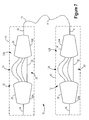
- FIG. 7 illustrates an optical filter system constructed using the filters of FIG. 6 .
- FIG. 8A illustrates a filter that is suitable for use as a first filter component and/or a second filter component.
- the filter includes an array waveguide grating having a plurality of array waveguides. At least a portion of the array waveguides include an effective length tuner for tuning the effective length of a array waveguide.
- FIG. 8B illustrates a filter that is suitable for use as a first filter component and/or a second filter component.
- the filter includes an array waveguide grating having a plurality of array waveguides.
- An effective length tuner is configured to tune the effective length of the array waveguides.
- FIG. 11A illustrates a filter that is suitable for use as a first filter component and/or a second filter component.
- the filter includes an array waveguide grating having a plurality of array waveguides.
- a reflector is positioned at an end of each array waveguide.
- FIG. 12 illustrates an optical filter system constructed with a filter according to FIG. 11 A.
- FIG. 14A illustrates a suitable construction of an optical component having a filter.
- FIG. 14C is a cross section of the optical component shown in FIG. 14B taken at the line labeled A.
- FIG. 14E illustrates another embodiment of the cross section shown in FIG. 14 C.
- FIG. 14F illustrates a suitable construction for a reflector positioned on an array waveguide.
- the period of the first filter and the second filter can be less than the desired tuning range of the optical filter system.
- the bands of the first filter and the bands of the second filter can be made to overlap at any target wavelength within the desired tuning range of the optical system by tuning the first filter and/or the second filter over a range that is smaller than the desired tuning range of the optical filter system.
- reducing the period of the first filter and/or the second filter reduces the tuning range required by the first filter and/or the second filter.
- the first filter and/or the second filter need only a small tuning range to provide the optical filter system with the desired tuning range.
- the tuning range of the first filter and/or the second filter is reduced, the power requirements of the optical filter system are reduced. Additionally, tuning of the first filter and/or the second filters over a small range does not substantially affect the bandwidth of the optical filters. This is true even when conventional filters are used in the optical filter system. As a result, the optical filter system does not show substantial changes to the bandwidth over the tuning range of the optical filter system.
- the first filter component 12 A receives an input light signal from the input waveguide 14 .
- the input light signal can be a single channel light signal or a multiple channel light signal.
- the first filter component 12 A filters the input light signal and outputs a primary filtered light signal.
- the output profile shown in FIG. 2A has a plurality of periodically spaced wavelength bands.
- the output of the filter 22 can have wavelengths that fall within the wavelength bands shown in FIG. 2A while filtering out other wavelengths.
- the band period associated with the first filter component 12 A is different than the band period associated with the second filter component 12 B.
- FIG. 3A illustrates the output profile for a first filter component 12 A
- FIG. 3B illustrates the output profile for a second filter component 12 B.
- the first filter component 12 A has a smaller band period than the second filter component 12 B.
- FIG. 3C illustrates the output profile for an optical filter system including a first filter component 12 A with the output profile of FIG. 3A and a second filter component 12 B with the output profile of FIG. 3 B.
- the band labeled A in FIG. 3 A and the band labeled E in FIG. 3B overlap while no other bands substantially overlap.
- the output profile shown in FIG. 3C shows only the band labeled H where the band labeled A and the band labeled E overlap.
- the fixed second filter component 12 B can be configured to have an output profile with a band period equal to N times the channel separation and bands that are coincident with the channels in the light signals to be output by the optical filter system 10 .
- N is an integer equal to one or greater.
- the bands coincide with the channels to be output by the optical filter system 10 .
- These channels are labeled ⁇ 1 , ⁇ 5 , ⁇ 9 .
- Configuring a filter component 12 to have output profiles with bands that coincide with the desired channels can be done because the channels processed by optical networks often have a constant channel spacing. Further, configuring the fixed filter component 12 to have an output profile with bands that coincide with the channels to be output by the optical filter system 10 allows the optical filter system 10 to output the desired channels.
- FIG. 4B is the same as FIG. 3 B.
- FIG. 4A shows the first filter component 12 A tuned so the band labeled B is moved to overlap with the band labeled F. This movement is illustrated by the arrow labeled M in FIG. 4 A.
- the output profile of the filter system 10 shown in FIG. 4C shows a band labeled H at the overlap of band labeled B and the band labeled F.
- the optical filter system 10 outputs a light signal having wavelengths in the band labeled H in FIG. 4 C.
- the first filter component 12 A and the second filter component 12 B can have different bandwidths.
- the filter component 12 with the narrower bandwidth determines the bandwidth for the optical filter system 10 .
- each of the filter components 12 is tunable, providing one of the filter components 12 with a larger bandwidth than the other filter component 12 reduces the accuracy that is required when tuning the filter components 12 such that the bands overlap. For instance, only the filter component 12 with the narrower bandwidth needs to be precisely tuned to a particular band.
- the filter component 12 with the broader bandwidth can be tuned so as to overlap the narrower bandwidth but does not need precise tuning.
- the tunable filter 22 can have the narrower bandwidth.
- the first filter component 12 A and the second filter component 12 B can both be tunable to provide a tunable optical filter system 10 .
- FIG. 3A can be the output profile of a tunable first filter component 12 A and
- FIG. 3B can be the output profile of a second tunable filter component 12 .
- the first filter component 12 A is shown as having a smaller band period than the second filter component, however, the first filter component 12 A can have a larger band period than the second filter component.
- the optical filter system 10 can be tuned to produce an output light signal having the wavelengths in the band labeled H in FIG. 3 B.
- FIG. 5 A through FIG. 5C illustrates the optical component 40 system of FIG. 3 A through FIG. 3C tuned to produce an output light signal having wavelengths in the band labeled H.
- FIG. 5A illustrates the output profile of the first filter component 12 A.
- FIG. 5B illustrates the output profile of the second filter component 12 B.
- FIG. 5C illustrates the output profile of the optical filter system 10 .
- the optical filter system of FIG. 5 A through FIG. 5C can be tuned to any wavelength in the desired range by constructing the first filter component such that the tuning range of the first filter component is at least equal to the band period of the first filter component and by constructing the second filter component such that the tuning range of the second filter component is at least equal to the band period of the second filter component.
- the tuning range of a filter components can be as small as the band period of the filter component while providing the optical filter system with a large tuning range.
- the optical filter system can be constructed such that the tuning range of the optical filter system is wide enough to cover the C or L band.
- Suitable filters 22 for use as a first filter component 12 A and/or a second filter component 12 B include, but are not limited to, Fabry Perot type filters, Mach Zender lattice type filters and multiple Bragg gratings filters.
- FIG. 6 illustrates another example of a filter 22 that is suitable for use as a first filter component 12 A and/or a second filter component 12 B.
- the filter 22 includes an array waveguide grating 24 providing optical communication between light distribution component s 26 . At least one input waveguide 14 is in optical communication with a first light distribution component 26 A and at least one output waveguide 16 is in optical communication with a second light distribution component 26 B.
- the second light distribution component 26 B has an input side 28 and an output side 30 .
- the light signal fraction traveling through a long array waveguide 32 enters the second light distribution component 26 B in a different phase than the light signal fraction traveling along the shorter array waveguide 32 .
- the light signal fraction entering the second light distribution component 26 B from each of the array waveguides 32 combines to re-form the light signal. Because the array waveguide 32 causes a phase differential between the light signal fractions entering the second light distribution component 26 B from adjacent array waveguides 32 , the light signal is diffracted at an angle labeled, ⁇ .
- the second light distribution component 26 B is constructed to converge the light signal at a location on the output side 30 of the second light distribution component 26 B.
- the location where the light signal is incident on the output side 30 of the second light distribution component 26 B is a function of the diffraction angle, ⁇ .
- the phase differential causes the light signal to be converged at the output waveguide 16 . As a result, the light signal appears on the output waveguide 16 .
- ⁇ L is a different fraction of the wavelength for each channel, the amount of the phase differential is different for different channels.
- the light signal includes a plurality of channels, different channels are diffracted at different angles and are accordingly converged at different locations on the output side 30 .
- each of the different channels is converged at a different location on the output side 30 . Since one of the channels can typically be converged on the output waveguide 16 , the output waveguide 16 generally carries only one of the channels at a time.
- the phase differential caused by ⁇ L will be the same for two or more wavelengths of light. Wavelengths of light with the same phase differential will have the same diffraction angle ⁇ . Each wavelength with the same diffraction angle ⁇ is incident on the same region of the output side 30 . As a result, the output waveguide 16 can carry more than one band of light. Additionally, the wavelengths that will have the same phase differential will each be spaced apart by the same wavelength band period. Hence, the filter 22 is periodic because the output waveguide 16 can carry a plurality of bands with a constant band period.
- Changing the value of ⁇ L changes the value of the band period. A smaller ⁇ L increases the band period while a larger ⁇ L decreases the band period.
- the bandwidth of the filter 22 can be changed by changing the size of the inlet port 38 of the output waveguide 16 .
- a smaller inlet port 38 allows a smaller range of wavelengths to enter the output waveguide 16 and accordingly reduces the bandwidth.
- a larger inlet port 38 allows a larger range of wavelengths to enter the output waveguide 16 and accordingly increases the bandwidth.
- the filter 22 can include an electronic temperature controller (not shown), TEC, for controlling the temperature of the filter 22 .
- a TEC is typically includes a heater and/or cooler for changing the temperature of the filter 22 and electronics for maintaining the filter 22 at a particular temperature.
- the temperature of the TEC can be adjusted to change the channel that is produced on the output waveguide 16 . For instance, increasing the temperature of the filter 22 causes the index of refraction of the array waveguides 32 to increase and accordingly increases the effective length of the array waveguides 32 . Increasing the effective length of the array waveguides 32 , increases the value of ⁇ L and causes the channels to shift in the direction of the arrow labeled A in FIG. 6 . Hence, increasing the temperature of the filter 22 causes the band(s) produced by the filter 22 to shift toward longer wavelengths. Alternatively, decreasing the temperature of the filter 22 causes the band(s) produced by the filter 22 to shift toward shorter wavelengths.
- FIG. 7 illustrates an optical filter system 10 constructed with a filter 22 according to FIG. 6 .
- the optical filter system 10 includes an optical component 40 having a first filter 22 according to FIG. 6 and an optical component 40 having a second filter 22 according to FIG. 6 .
- the first filter 22 serves as the first filter component 12 A and the second filter 22 serves as the second filter component 12 B.
- the first filter component 12 A is constructed to have a different ⁇ L that the second filter component 12 B in order to provide each of the filter components 12 with a different band period.
- the first filter component 12 A and the second filter component 12 B can be integrated on the same optical component 40 with a transition waveguide 15 serving as the output waveguide 16 of the first filter component 12 A and the input waveguide 14 of the second filter component 12 B.
- FIG. 7 illustrates an optical fiber 41 connecting the output waveguide 16 of the first filter component 12 A with the input waveguide 14 of the second filter component 12 B.
- the optical fiber 41 allows the optical components 40 to be spaced apart from one another. Spacing the optical components 40 apart from one another increases the thermal isolation of the filter components 12 from one another above what could be achieved by integrating the first optical component 40 and the second optical component 40 on the same optical component 40 .
- the increased thermal isolation allows each filter component to be tuned to a different temperature without substantial interference from other filter components. As a result, each of the filter components 12 can be independently tuned.
- the tuning range of the filter 22 illustrated in FIG. 6 is generally too narrow to provide effective tuning. However, because the optical filter system 10 can employ filters 22 components with a low tuning range, these filters 22 can be effective with a large tuning range in the context of the optical filter system 10 .
- FIG. 8 A and FIG. 8B illustrate an adaptation of the filter 22 illustrated in FIG. 6 .
- At least a portion of the array waveguides 32 include an effective length tuner 42 as shown in FIG. 8 A.
- the effective length tuners 42 can be integrated into a common effective length tuner 44 configured to change the effective length of a plurality of array waveguides 32 as shown in FIG. 8 B. Construction of these tunable filters 22 is taught in U.S. patent application Ser. No. 09/845,685; filed on Apr. 30, 2001; entitled “Tunable Filter” and incorporated herein in its entirety.
- Suitable effective length tuners 42 include, but are not limited to, temperature control devices for changing the temperature for all or a portion of an array waveguide 32 and current injection devices for injecting a current or an electrical field through an array waveguide 32 .
- the temperature control devices can be resistive heaters and the current injection devices can be electrical contacts arranged for injecting a current through the array waveguide 32 .
- the effective length tuners 42 are configured to change the effective length of an array waveguide 32 by changing the effective length of a portion of the array waveguide 32 . For instance, increasing the temperature of a portion of an array waveguide 32 causes the index of refraction of the portion of the array waveguide 32 to increase and accordingly increases the effective length of the array waveguide 32 . Further, decreasing the temperature of a portion of an array waveguide 32 causes the index of refraction of the portion of the array waveguide 32 to decrease and accordingly decreases the effective length of the array waveguide 32 .
- the effective length tuners 42 are arranged such that when the effective length tuners 42 are engaged so as to change the effective length of the array waveguides 32 , the change to the effective length of each array waveguide 32 is different and that the difference in the amount of change for adjacent array waveguides 32 is a constant.
- the effective length tuners 42 can be arranged so the amount of the effective length change to the j th array waveguide 32 , ⁇ 1 j , can be expressed (j) ⁇ 1 j , (j ⁇ 1) ⁇ 1 j , (N ⁇ j) ⁇ 1 j or (N ⁇ j+1) ⁇ 1 j .
- the effective length tuners 42 provide for tunability of the filter 22 .
- a TEC can be used in conjunction with a filter 22 according to FIG. 8 A and FIG. 8 B.
- the TEC is used to maintain the temperature of the filter 22 at some constant value.
- the effective length tuners 42 include temperature controllers
- the constant temperature can serves as a baseline for the effective length tuners 42 . For instance, any heating effects from the effective length tuners 42 can be made relative to the baseline temperature.
- FIG. 9 illustrates an embodiment of an optical filter system 10 employing a filter 22 according to FIG. 8 A and FIG. 8 B.
- the optical filter system 10 includes a first filter 22 serving as the first filter component 12 A and a second filter 22 serving as a second filter component 12 B.
- the first filter component 12 A is constructed to have a different ⁇ L that the second filter component 12 B in order to provide each of the filter components 12 with a different band period.
- the first filter component 12 A and the second filter component 12 B are integrated on the same optical component 40 with a transition waveguide 15 serving as the output waveguide 16 of the first filter component 12 A and the input waveguide 14 of the second filter component 12 B.
- Each of the filters 22 is associated with different effective length tuners 42 . Because the effective length tuners 42 have localized effects, the effects from effective length tuners 42 associated with one filter 22 do not affect other effective length tuners 42 on the same optical component 40 .
- FIG. 10 illustrates an embodiment of an optical filter system 10 employing a filter 22 according to FIG. 8 A and FIG. 8 B.
- An input waveguide 14 and an output waveguide 16 are in optical communication with the first light distribution component 26 A.
- a first array waveguide grating 24 A and a second array waveguide grating 24 B are positioned between a first light distribution component 26 A and a second light distribution component 26 B.
- the first array waveguide grating 24 A is constructed with a different ⁇ L than the second filter component 12 B in order to provide the first filter component 12 A and the second filter component 12 B with different band period.
- a transition waveguide 15 connects one region of the output side 30 with another region of the output side 30 .
- the first filter component 12 A and the second filter component 12 B use the same first light distribution component 26 A and second light distribution component 26 B. As a result, the size of the optical component 40 system is reduced.
- a light signal from the input waveguide 14 travels through the first light distribution component 26 A to the first array waveguide grating 24 A as illustrated by the arrow labeled A.
- the light signal from the first array waveguide grating 24 A travels through the second light distribution component 26 B to an input port of the transition waveguide 15 as illustrated by the arrow labeled B.
- the first array waveguide grating 24 A and the second light distribution component 26 B serve as the first filter component 12 A. Accordingly, the light signal traveling through the transition waveguide 15 is the primary filtered light signal.
- the primary filtered light signal enters the second light distribution component 26 B through an output port of the transition waveguide 15 .
- the primary filtered light signal travels from the output port to the second array waveguide grating 24 B as illustrated by the arrow labeled C.
- the primary filtered light signal travels from the second array waveguide grating 24 B through the first light distribution component 26 A to the output waveguide 16 as illustrated by the arrow labeled D.
- the second array waveguide grating 24 B and the first light distribution component 26 A serve as the second filter component 12 B.
- the first light distribution component 26 A and the second array waveguide grating 24 B filter the primary filtered signal to produce the output light signal.
- the first array waveguide grating 24 A is associated with different effective length tuners 42 than the second array waveguide grating 24 B. Because the first array waveguide grating 24 A and the second light distribution component 26 B serve as the first filter component 12 A, the first filter component 12 A is tuned by tuning the effective length tuners 42 associated with the first array waveguide 32 . Because the second array waveguide grating 24 B and the first light distribution component 26 A serve as the second filter component 12 B, the second filter component 12 B is tuned by tuning the effective length tuners 42 associated with the second array waveguide grating 24 B. As a result, the first filter component 12 A and the second filter component 12 B can be independently tuned.
- the localized characteristics of the effective length tuners 42 reduce interaction between the effective length tuners 42 associated with different array waveguide gratings 24 .
- Each of the filters 22 illustrated above can be constructed with a single light distribution component 26 by positioning reflectors 50 along the array waveguides 32 as shown in FIG. 11 A.
- the filter 22 includes an input waveguide 14 and an output waveguide 16 that are each connected to the same side of the light distribution component 26 .
- the array waveguides 32 include a reflector 50 configured to reflect light signals. The use of reflectors 50 can eliminate the need for a second light distribution component 26 B and can accordingly reduce the size of the filter 22 as well as the size of the optical filter system 10 .
- a light signal from the input waveguide 14 is distributed to the array waveguides 32 .
- the array waveguides 32 carry the light signal portions to the reflector 50 where they are reflected back toward the light distribution component 26 .
- the light distribution component 26 combines the light signal portions and converges the light signal at the output waveguide 16 .
- the output waveguide 16 carries the light signal.
- a TEC can be used to tune the output of a filter 22 according to FIG. 11 A.
- one or more of the array waveguides 32 can include an effective length tuner 42 as shown in FIG. 11 B.
- the effective length tuners 42 can be operated so as to tune the output of the filter 22 .
- the reflectors 50 can be formed by an edge 52 of the optical component 40 as shown in FIG. 11 C.
- the edge 52 of the optical component 40 can include a reflective coating in order to increase reflection of the light signals at the edge 52 of the optical component 40 .
- a filter 22 such as the filter 22 of FIG. 6 or FIG. 8A can be fabricated with an input waveguide 14 and an output waveguide 16 in optical communication with the light distribution component 26 as well as an input waveguide 14 and an output waveguide 16 in optical communication with the second light distribution component 26 B.
- the filter 22 can then be cleaved along a line such as the dashed line labeled B in FIG. 6.
- a reflective coating can be formed on all or a portion of the edge 52 formed by cleaving.
- An input waveguide 14 in one of the filters 22 will serve as an output waveguide 16 and an output waveguide 16 in one of the filters will serve as an input waveguide 14 .
- An optical fiber 41 connects the output waveguide 16 of the first filter component 12 A with the input waveguide 14 of the second filter component 12 B.
- the optical fiber 41 allows the optical components 40 to be spaced apart from one another. Spacing the optical components 40 apart from one another increases the thermal isolation of the filter components 12 from one another above what could be achieved by integrating the first filter component 12 A and the second filter component 12 B on the same optical component 40 .
- the increased thermal isolation allows each filter component to be tuned to a different temperature without substantial interference from other filter components. As a result, each of the filter components 12 can be independently tuned.
- FIG. 13 illustrates an embodiment of an optical filter system 10 employing a filter 22 according to FIG. 11 B.
- An input waveguide 14 and an output waveguide 16 are in optical communication with the light distribution component 26 .
- a transition waveguide 15 connects one region of the light distribution component 26 with another region of the light distribution component 26 .
- a first array waveguide grating 24 A and a second array waveguide grating 24 B are in optical communication with the light distribution component 26 .
- the first array waveguide grating 24 A is constructed with a different ⁇ L than the second filter component 12 B in order to provide the first filter component 12 A and the second filter component 12 B with different band period.
- the optical filter system 10 employs a single light distribution component 26 and accordingly has a reduced size.
- the localized characteristics of the effective length tuners 42 reduce interaction between the effective length tuners 42 associated with different array waveguide gratings 24 .
- one of the filter components 12 can be fixed.
- the first filter component 12 A and the second filter component 12 B need not each include a TEC in the optical filter systems 10 of FIG. 7 and FIG. 12 .
- the first array waveguide grating 24 A and the second array waveguide grating 24 B need not each include effective length tuners 42 in the optical filter systems 10 of FIG. 9, FIG. 10 and FIG. 13 .
- the optical filter system 10 can employ a different type of effective length tuner 42 in the first array waveguide grating 24 A than in the second array waveguide grating 24 B.
- the first array waveguide grating 24 A can include different effective length tuners 42 associated with each array waveguide 32 while the second array waveguide grating 24 B includes a common effective length tuner 44 .
- the size of the filter components can be reduced by selecting a narrow band period. Reducing the band period allows these filter components to be constructed with smaller light distribution components. As a result, reducing the band period allows the size of the filter components to be reduced.
- FIG. 14A illustrated the base 62 positioned over the heater of a TEC, however, the TEC is optional in many embodiments.
- FIG. 14B has an array waveguide grating 24 with effective length tuners 42 .
- FIG. 14D is a cross section of the optical component 40 taken at across an effective length tuner 42 at the line labeled B in FIG. 14 B.
- the effective length tuner 42 includes a layer of metal 68 formed over the light transmitting medium 60 .
- a metal trace 70 connects each of the effective length tuners 42 in series.
- the electrical trace ends at pads 72 . When an electrical potential is applied between the pads 72 , the resulting current causes heating of the effective length tuners 42 .
- a cladding layer 74 can be optionally be positioned over the light transmitting medium 60 as shown in FIG. 14 E.
- the cladding layer 74 can have an index of refraction less than the index of refraction of the light transmitting medium 60 so light signals from the light transmitting medium 60 are reflected back into the light transmitting medium 60 .
- a component constructed as shown in FIG. 14 A through FIG. 14D can be constructed by obtaining a component having a light transmitting medium 60 positioned over a base 62 .
- the component can be obtained from a supplier or can be fabricated.
- a mask is formed so the regions of the light transmitting medium 60 where a ridge 64 is to be formed are protected.
- An etch is then performed so as to form the ridges 64 to the desired height.
- the masks are removed.
- Any effective length tuners 42 can then be constructed. For instance, when the effective length tuners 42 include electrical contacts or metal layers, the electrical contacts can be grown or deposited on the optical component 40 .
- the optical component 40 is to include a TEC, the component can then be bonded to the temperature controller of the TEC using a material such as epoxy.
- the array waveguides 32 of FIG. 14B are shown as having a curved shape.
- a suitable curved waveguide is taught in U.S. patent application Ser. No. 09/756,498, filed on Jan. 8, 2001, entitled “An efficient Curved Waveguide” and incorporated herein in its entirety.
- Other filter 22 constructions can also be employed.
- filters 22 can be constructed with straight waveguides as taught in U.S. patent application Ser. No. 09/724,175, filed on Nov. 28, 2000, entitled “A Compact Integrated Optics Based Array waveguide Demultiplexer” and incorporated herein in its entirety.
- FIG. 14F illustrates a suitable construction of a reflector 50 .
- the reflector 50 includes a reflecting surface 76 positioned at an end of an array waveguide 32 .
- the reflecting surface 76 is configured to reflect light signals from an array waveguide 32 back into the array waveguide 32 .
- the reflecting surface 76 extends below the base 62 of the ridge 64 .
- the reflecting surface 76 can extend through the light transmitting medium 60 to the base 62 and in some instances can extend into the base 62 .
- the reflecting surface 76 extends to the base 62 because the light signal carrying region 66 is positioned in the ridge 64 as well as below the ridge 64 as evident in FIG. 14 C.
- FIG. 9, FIG. 10 and FIG. 13 illustrate a curved transition waveguide 15
- the transition waveguide can be constructed from a plurality of straight branches with a reflector 50 positioned at the intersection of the straight branches.
- the use of straight branches can reduce some of the complexities introduced by sharply curved waveguides.
- these filters 22 can include additional output waveguides 16 configured to serve as secondary output waveguides 18 .
- the additional output waveguides 16 can be positioned to receive the light signals that have been filtered out by the filter 22 .
- optical filter system 10 is described in the context of a first filter component 12 A and a second filter component 12 B, the advantages of the optical filter system 10 can be enhanced by constructing the optical filter system 10 with more than two filter components 12 .
Abstract
Description
Claims (42)
Priority Applications (1)
| Application Number | Priority Date | Filing Date | Title |
|---|---|---|---|
| US09/872,472 US6674929B2 (en) | 2001-06-01 | 2001-06-01 | Tunable optical filter |
Applications Claiming Priority (1)
| Application Number | Priority Date | Filing Date | Title |
|---|---|---|---|
| US09/872,472 US6674929B2 (en) | 2001-06-01 | 2001-06-01 | Tunable optical filter |
Publications (2)
| Publication Number | Publication Date |
|---|---|
| US20020181832A1 US20020181832A1 (en) | 2002-12-05 |
| US6674929B2 true US6674929B2 (en) | 2004-01-06 |
Family
ID=25359623
Family Applications (1)
| Application Number | Title | Priority Date | Filing Date |
|---|---|---|---|
| US09/872,472 Expired - Lifetime US6674929B2 (en) | 2001-06-01 | 2001-06-01 | Tunable optical filter |
Country Status (1)
| Country | Link |
|---|---|
| US (1) | US6674929B2 (en) |
Cited By (10)
| Publication number | Priority date | Publication date | Assignee | Title |
|---|---|---|---|---|
| US20030025971A1 (en) * | 1998-11-17 | 2003-02-06 | Corvis Corporation | Optical communications systems, devices, and methods |
| US20030128908A1 (en) * | 2001-12-21 | 2003-07-10 | Thorsten Spott | Planar optical circuit |
| US20040071386A1 (en) * | 2002-04-09 | 2004-04-15 | Nunen Joris Van | Method and apparatus for homogeneous heating in an optical waveguiding structure |
| US20040136717A1 (en) * | 2002-09-03 | 2004-07-15 | Xinxiong Zhang | Non-blocking tunable filter with flexible bandwidth for reconfigurable optical networks |
| US20040252938A1 (en) * | 2002-05-20 | 2004-12-16 | Thomas Ducellier | Reconfigurable optical add-drop module, system and method |
| US6917736B1 (en) * | 2002-05-09 | 2005-07-12 | Purdue Research Foundation | Method of increasing number of allowable channels in dense wavelength division multiplexing |
| US20050175369A1 (en) * | 2002-05-27 | 2005-08-11 | Kabushiki Kaisha Toshiba | Fixing unit |
| US20060083515A1 (en) * | 2004-10-20 | 2006-04-20 | Kwangju Institute Of Science And Technology | WDM-PON having optical source of self-injection locked fabry-perot laser diode |
| US20080231943A1 (en) * | 2007-03-22 | 2008-09-25 | Sorin Wayne V | Periodically filtered broadband light source |
| US20230176302A1 (en) * | 2021-12-08 | 2023-06-08 | Viavi Solutions Inc. | Photonic structure using optical heater |
Families Citing this family (6)
| Publication number | Priority date | Publication date | Assignee | Title |
|---|---|---|---|---|
| SE521419C2 (en) * | 2001-11-09 | 2003-10-28 | Ericsson Telefon Ab L M | MMI-based device |
| US20040234198A1 (en) * | 2003-03-21 | 2004-11-25 | Aegis Semiconductor, Inc. | Tunable and switchable multiple-cavity thin film optical filters |
| KR20070020166A (en) * | 2003-08-26 | 2007-02-20 | 레드시프트 시스템즈 코포레이션 | Infrared camera system |
| US7221827B2 (en) * | 2003-09-08 | 2007-05-22 | Aegis Semiconductor, Inc. | Tunable dispersion compensator |
| JP5644630B2 (en) * | 2011-03-30 | 2014-12-24 | 沖電気工業株式会社 | Optical waveguide device |
| CN109239940B (en) * | 2018-11-02 | 2021-05-07 | 京东方科技集团股份有限公司 | Light splitting device and manufacturing method thereof, light dispersion method and spectrometer |
Citations (35)
| Publication number | Priority date | Publication date | Assignee | Title |
|---|---|---|---|---|
| US4618210A (en) | 1982-06-09 | 1986-10-21 | Nec Corporation | Optical switch of switched directional coupler type |
| US4747654A (en) | 1983-05-19 | 1988-05-31 | Yi Yan Alfredo | Optical monomode guidance structure including low resolution grating |
| JPS63197923A (en) | 1987-02-13 | 1988-08-16 | Nec Corp | Optical switch for matrix |
| US4813757A (en) | 1986-11-26 | 1989-03-21 | Hitachi, Ltd. | Optical switch including bypass waveguide |
| US4846542A (en) | 1987-10-09 | 1989-07-11 | Oki Electric Industry Co., Ltd. | Optical switch matrix |
| JPH02179621A (en) | 1988-12-29 | 1990-07-12 | Oki Electric Ind Co Ltd | Optical matrix switch |
| US5002350A (en) | 1990-02-26 | 1991-03-26 | At&T Bell Laboratories | Optical multiplexer/demultiplexer |
| US5013113A (en) | 1989-08-31 | 1991-05-07 | The United States Of America As Represented By The Secretary Of The Air Force | Lossless non-interferometric electro-optic III-V index-guided-wave switches and switching arrays |
| US5039993A (en) | 1989-11-24 | 1991-08-13 | At&T Bell Laboratories | Periodic array with a nearly ideal element pattern |
| US5243672A (en) | 1992-08-04 | 1993-09-07 | At&T Bell Laboratories | Planar waveguide having optimized bend |
| WO1994007178A1 (en) * | 1992-09-24 | 1994-03-31 | Interuniversitair Micro-Elektronica | Integrated tunable optical filter |
| JPH06186598A (en) | 1993-06-01 | 1994-07-08 | Hitachi Ltd | Optical exchanger |
| EP0647861A1 (en) | 1993-09-10 | 1995-04-12 | AT&T Corp. | Polarization-independent optical wavelength selective coupler |
| US5412744A (en) | 1994-05-02 | 1995-05-02 | At&T Corp. | Frequency routing device having a wide and substantially flat passband |
| US5450511A (en) | 1992-04-29 | 1995-09-12 | At&T Corp. | Efficient reflective multiplexer arrangement |
| US5467418A (en) | 1994-09-02 | 1995-11-14 | At&T Ipm Corp. | Frequency routing device having a spatially filtered optical grating for providing an increased passband width |
| US5488500A (en) * | 1994-08-31 | 1996-01-30 | At&T Corp. | Tunable add drop optical filtering method and apparatus |
| US5542010A (en) * | 1993-02-19 | 1996-07-30 | At&T Corp. | Rapidly tunable wideband integrated optical filter |
| US5581643A (en) | 1994-12-08 | 1996-12-03 | Northern Telecom Limited | Optical waveguide cross-point switch |
| US5706377A (en) | 1996-07-17 | 1998-01-06 | Lucent Technologies Inc. | Wavelength routing device having wide and flat passbands |
| US5841931A (en) | 1996-11-26 | 1998-11-24 | Massachusetts Institute Of Technology | Methods of forming polycrystalline semiconductor waveguides for optoelectronic integrated circuits, and devices formed thereby |
| US5938811A (en) | 1997-05-23 | 1999-08-17 | Lucent Technologies Inc. | Method for altering the temperature dependence of optical waveguides devices |
| US5991477A (en) * | 1994-08-02 | 1999-11-23 | Fujitsu Limited | Optical transmission system, optical multiplexing transmission system, and related peripheral techniques |
| US6021242A (en) * | 1997-07-23 | 2000-02-01 | Sumitomo Electric Industries | Diffraction grating type band-pass filter and method of making the same |
| EP0985942A2 (en) | 1998-08-03 | 2000-03-15 | Lucent Technologies Inc. | Add/drop filter for a multi-wavelength lightwave system |
| US6108478A (en) | 1997-02-07 | 2000-08-22 | Bookham Technology Limited | Tapered rib waveguide |
| US6118909A (en) | 1997-10-01 | 2000-09-12 | Lucent Technologies Inc. | Athermal optical devices |
| US6256428B1 (en) * | 1999-02-19 | 2001-07-03 | Corning Incorporated | Cascading of tunable optical filter elements |
| US6272270B1 (en) | 1997-07-11 | 2001-08-07 | Oki Electric Industry Co., Ltd. | Optical wave combining/splitting device |
| US6337937B1 (en) * | 1998-05-18 | 2002-01-08 | Sumitomo Electric Industries, Ltd. | Optical filter and method of making the same |
| US6486984B1 (en) * | 1999-06-07 | 2002-11-26 | Agilent Technologies, Inc. | Wavelength monitor using hybrid approach |
| US20020186928A1 (en) * | 2001-06-08 | 2002-12-12 | Kevin Curtis | Tunable optical filter |
| US6542666B2 (en) * | 2000-03-13 | 2003-04-01 | The Furukawa Electric Co., Ltd. | Optical component |
| US6546167B1 (en) * | 2001-12-11 | 2003-04-08 | Corning Incorporated | Tunable grating optical device |
| US6549328B2 (en) * | 2001-08-14 | 2003-04-15 | Fujitsu Limited | Acousto-optic tunable filter |
-
2001
- 2001-06-01 US US09/872,472 patent/US6674929B2/en not_active Expired - Lifetime
Patent Citations (35)
| Publication number | Priority date | Publication date | Assignee | Title |
|---|---|---|---|---|
| US4618210A (en) | 1982-06-09 | 1986-10-21 | Nec Corporation | Optical switch of switched directional coupler type |
| US4747654A (en) | 1983-05-19 | 1988-05-31 | Yi Yan Alfredo | Optical monomode guidance structure including low resolution grating |
| US4813757A (en) | 1986-11-26 | 1989-03-21 | Hitachi, Ltd. | Optical switch including bypass waveguide |
| JPS63197923A (en) | 1987-02-13 | 1988-08-16 | Nec Corp | Optical switch for matrix |
| US4846542A (en) | 1987-10-09 | 1989-07-11 | Oki Electric Industry Co., Ltd. | Optical switch matrix |
| JPH02179621A (en) | 1988-12-29 | 1990-07-12 | Oki Electric Ind Co Ltd | Optical matrix switch |
| US5013113A (en) | 1989-08-31 | 1991-05-07 | The United States Of America As Represented By The Secretary Of The Air Force | Lossless non-interferometric electro-optic III-V index-guided-wave switches and switching arrays |
| US5039993A (en) | 1989-11-24 | 1991-08-13 | At&T Bell Laboratories | Periodic array with a nearly ideal element pattern |
| US5002350A (en) | 1990-02-26 | 1991-03-26 | At&T Bell Laboratories | Optical multiplexer/demultiplexer |
| US5450511A (en) | 1992-04-29 | 1995-09-12 | At&T Corp. | Efficient reflective multiplexer arrangement |
| US5243672A (en) | 1992-08-04 | 1993-09-07 | At&T Bell Laboratories | Planar waveguide having optimized bend |
| WO1994007178A1 (en) * | 1992-09-24 | 1994-03-31 | Interuniversitair Micro-Elektronica | Integrated tunable optical filter |
| US5542010A (en) * | 1993-02-19 | 1996-07-30 | At&T Corp. | Rapidly tunable wideband integrated optical filter |
| JPH06186598A (en) | 1993-06-01 | 1994-07-08 | Hitachi Ltd | Optical exchanger |
| EP0647861A1 (en) | 1993-09-10 | 1995-04-12 | AT&T Corp. | Polarization-independent optical wavelength selective coupler |
| US5412744A (en) | 1994-05-02 | 1995-05-02 | At&T Corp. | Frequency routing device having a wide and substantially flat passband |
| US5991477A (en) * | 1994-08-02 | 1999-11-23 | Fujitsu Limited | Optical transmission system, optical multiplexing transmission system, and related peripheral techniques |
| US5488500A (en) * | 1994-08-31 | 1996-01-30 | At&T Corp. | Tunable add drop optical filtering method and apparatus |
| US5467418A (en) | 1994-09-02 | 1995-11-14 | At&T Ipm Corp. | Frequency routing device having a spatially filtered optical grating for providing an increased passband width |
| US5581643A (en) | 1994-12-08 | 1996-12-03 | Northern Telecom Limited | Optical waveguide cross-point switch |
| US5706377A (en) | 1996-07-17 | 1998-01-06 | Lucent Technologies Inc. | Wavelength routing device having wide and flat passbands |
| US5841931A (en) | 1996-11-26 | 1998-11-24 | Massachusetts Institute Of Technology | Methods of forming polycrystalline semiconductor waveguides for optoelectronic integrated circuits, and devices formed thereby |
| US6108478A (en) | 1997-02-07 | 2000-08-22 | Bookham Technology Limited | Tapered rib waveguide |
| US5938811A (en) | 1997-05-23 | 1999-08-17 | Lucent Technologies Inc. | Method for altering the temperature dependence of optical waveguides devices |
| US6272270B1 (en) | 1997-07-11 | 2001-08-07 | Oki Electric Industry Co., Ltd. | Optical wave combining/splitting device |
| US6021242A (en) * | 1997-07-23 | 2000-02-01 | Sumitomo Electric Industries | Diffraction grating type band-pass filter and method of making the same |
| US6118909A (en) | 1997-10-01 | 2000-09-12 | Lucent Technologies Inc. | Athermal optical devices |
| US6337937B1 (en) * | 1998-05-18 | 2002-01-08 | Sumitomo Electric Industries, Ltd. | Optical filter and method of making the same |
| EP0985942A2 (en) | 1998-08-03 | 2000-03-15 | Lucent Technologies Inc. | Add/drop filter for a multi-wavelength lightwave system |
| US6256428B1 (en) * | 1999-02-19 | 2001-07-03 | Corning Incorporated | Cascading of tunable optical filter elements |
| US6486984B1 (en) * | 1999-06-07 | 2002-11-26 | Agilent Technologies, Inc. | Wavelength monitor using hybrid approach |
| US6542666B2 (en) * | 2000-03-13 | 2003-04-01 | The Furukawa Electric Co., Ltd. | Optical component |
| US20020186928A1 (en) * | 2001-06-08 | 2002-12-12 | Kevin Curtis | Tunable optical filter |
| US6549328B2 (en) * | 2001-08-14 | 2003-04-15 | Fujitsu Limited | Acousto-optic tunable filter |
| US6546167B1 (en) * | 2001-12-11 | 2003-04-08 | Corning Incorporated | Tunable grating optical device |
Non-Patent Citations (139)
| Title |
|---|
| Abe, et al., Optical Path Length Trimming Technique using Thin Film Heaters for Silica-Based Waveguides on Si, Electronics Letters , Sep. 12, 1996, vol. 32-No. 19, pp. 1818-1820. |
| Albert, J., Planar Fresnel Lens Photoimprinted in a Germanium-Doped Silica Optical Waveguide, Optics Letters, May 15, 1995, vol. 20-No. 10, pp 1136-1138. |
| Aman, M.C., Calculation of Metal-Clad Ridge-Waveguide (MCRW) Laser Modes by Mode Coupling Technique, Journal of Lightwave Technology, vol. LT-4, No. 6, Jun. 1986, p. 689-693. |
| Amann, M.C. et al, Calculation Of The Effective Refractive-Index Step For The Metal-Cladded-Ridge-Waveguide Laser, Applied Optics, vol. 20, No. 8, Apr. 15, 1981, p. 1483-1486. |
| Baba, S. et al., A Novel Integrated-Twin-Guide (ITG) Optical Switch with a Built-in TIR Region; IEEE Photonics Technology Letters; vol. 4, No. 5, May 1992, p. 486-488. |
| Benson, T.M., Etched-Wall Bent-Guide Structure for Integrated Optics in the III-V Semiconductors; Journal of Lightwave Technology, vol. LT-2, No. 1, Feb. 1984; p. 31-34. |
| Berry, G.M. et al., Analysis Of Multiplayer Semiconductor Rib Waveguides With High Refractive Index Substrates, Electronics Letters; vol. 29, No. 22; Oct. 28, 1993, p. 1941-1942. |
| Betty, I. et al., A Robust, Low-Crosstalk, InGaAsP/InP Total-Internal-Reflection Switch For Optical Cross-Connect Application. |
| Burke, S.V., Spectral Index Method Applied to Coupled Rib Waveguides; Electronics Letters, vol. 25, No. 9, Apr. 27, 1989; p. 605-606. |
| Burns, W.K. et al., Mode Conversion in Planar-Dielectric Separating Waveguides; IEEE Journal of Quantum Electronics, vol. QE-11, No. 1, Jan. 1975; p. 32-39. |
| Cai, Y. et al., A Novel Three-Guide Optical Coupler Using A Taper-Formed Waveguide; j. Appl. Phys 69(5), Mar. 1991; p. 2810-2814. |
| Cavailles, J.A. et al., First Digital Optical Switch Based on InP/GaInAsP Double Heterostructure Waveguides; Electronics Letters, vol. 27, No. 9, Apr. 25, 1991, p. 699-700. |
| Chen, R.T. et al., Design and Manufacturing of WDM Devices; Proceedings of SPIE vol. 3234. |
| Clemens, et al., Wavelength-Adaptable Optical Phased Array in SiO2-Si, Photonics Technology Letters, Oct. 1995, vol. 7-No. 10, 1040-1041. |
| Dagli, N. et al., Analysis of Rib Dielectric Waveguides; IEEE Journal of Quantum Electronics, vol. QE-21, No. 4, Apr. 1985, p. 315-321. |
| Dagli, N. et al., Theoretical and Experimental Study of the Analysis and Modeling of Integrated Optical Components; IEEE Journal of Quantum electronics, vol. 24, No. 11, Nov. 1988; p. 2215-2226. |
| Deri, R.J., et al., Low-Loss GaAs/AIGaAs Waveguide Phase Modulator Using A W- Shaped Index Profile; Sep. 6, 1988. |
| Deri, R.J., et al., Low-Loss Multiple Quantum Well GaInAs/InP Optical Waveguides; Feb. 21, 1989. |
| Devaux, F. et al., 20Gbit/s Operation of a High-Efficiency InGaAsP/InGaAsP MQW Electroabsorption Modulator With 1.2-V Drive Voltage; IEEE Photonics Technology Letters, vol. 5, No. 11, Nov. 1993, p. 1288-1290. |
| Doerr, C. R. et al., 2×2 Waveength-Selective Cross Connect Capable of Switching 128 Channels in Sets of 8, PD8, pp. 1-3. |
| Doerr, C. R. et al., 2x2 Waveength-Selective Cross Connect Capable of Switching 128 Channels in Sets of 8, PD8, pp. 1-3. |
| Doerr, C. R. et al., Automatic Wavelength Channel-By-Channel Equalizer, PD20, pp. 227-229. |
| Doerr, C.R. et al., Chirping Of The Waveguide Grating Router For Free-Spectral-Range Mode Selection In The Multifrequency Laser, IEEE Photonics Technology Letters, Apr. 1996, vol. 8-No. 4, pp 500-502. |
| Doerr, C.R. et al., Chromatic Focal lane Displacement in the Parabolic Chirped Waveguide Grating Router, May 1997, vol. 9-No. 5, pp 625-627. |
| Dragone, c. Efficient N×N Star Couplers Using Fourier Optics, pp 479-48, Mar. 1989, vol. 7-No. 3, Journal of Lightwave Technology. |
| Dragone, c. Efficient NxN Star Couplers Using Fourier Optics, pp 479-48, Mar. 1989, vol. 7-No. 3, Journal of Lightwave Technology. |
| Fischer, et al., Singlemode Optical Switches Based on SOI Waveguides with Large Cross-Section, Electronics Letters, Mar. 3, 1994, vol. 30-No. 5, pp. 406-408. |
| Fischer, K. et al, Sensor Application Of SiON Integrated Optical Waveguides On Silicon; Elevier Sequoia, 1992; p. 209-213. |
| Fish, G. et al., Monolithic InP Optical Crossconnects: 4×4 and Beyond, JWB2-1, p. 19-21. |
| Fish, G. et al., Monolithic InP Optical Crossconnects: 4x4 and Beyond, JWB2-1, p. 19-21. |
| Furuta, H. et al, Novel Optical Waveguide For Integrated Optics, Applied Optics, vol. 13, No. 2, Feb. 1974, p. 322-326. |
| Gini, E. et al., Low Loss Self-Aligned Optical Waveguide Corner Mirrors in InGaAsP/InP, We P2.22. |
| Goel, K. et al Design Considerations for Low Switching Voltage Crossing Channel Switches; Journal of Lightwave Technology, vol. 6, No. 6, Jun. 1988; p. 881-886. |
| Granestrand, P. et al., Integrated Optics 4×4 Switch Matrix with Digital Optical Switches; Electronics Letters, vol. 26, No. 1, Jan. 4, 1990; p. 4-5. |
| Granestrand, P. et al., Integrated Optics 4x4 Switch Matrix with Digital Optical Switches; Electronics Letters, vol. 26, No. 1, Jan. 4, 1990; p. 4-5. |
| Himeno, A. et al., Loss Measurement and Analysis of High-Silica Reflection Bending Optical Waveguides, Journal of Lightwave Techology, Jan. 1988, vol. 6-No. 1, 41-46. |
| Hsu, K.Y. et al., Photonics devices and Modules, www.cc.nctu.edu.tw/~ctr/lee_mti/research_topic/photonic_devices_modules.htm, pp 1-3. |
| Hsu, K.Y. et al., Photonics devices and Modules, www.cc.nctu.edu.tw/˜ctr/lee_mti/research_topic/photonic_devices_modules.htm, pp 1-3. |
| Huang, T.C. et al., Depletion Edge Translation Waveguide Crossing Optical Switch; IEEE Photonics Technology Letters; vol. 1, No. 7, Jul. 1989, p. 168-170. |
| Hutcheson, L.D. et al., Comparison of Bending Losses in Integrated Optical Circuits; Optics Letters, vol. 5, No. 6, Jun. 1980, p. 360-362. |
| Inoue, H. et al, Low Loss GaAs Optical Waveguides, Journal of Lightwave Technology, vol. LT-3, No. 6, Dec. 1985; p. 204-209. |
| Irace, A. et al., Fast Silicon-on-Silicon Optoelectronic Router Based on a BMFET Device, Journal of Selected Topics on Quantum Electronics, Jan./Feb. 2000, vol. 6-No. 1, pp. 14-18. |
| Ito, F. et al., Carrier-Injection-Type Optical Switch In GaAs With A 1.06-1.55 mum Wavelength Range; Appl. Physics Letters, 54(2) Jan. 9, 1989; p. 134-136. |
| Ito, F. et al., Carrier-Injection-Type Optical Switch In GaAs With A 1.06-1.55 μm Wavelength Range; Appl. Physics Letters, 54(2) Jan. 9, 1989; p. 134-136. |
| Jackman, N. et al., Optical Cross Connects for Optical Networking; Bell Labs Technical Journal, Jan.-Mar. 1999; p. 262-281. |
| Johnston, I.R., et al., Silicon-Based Fabrication Process For Production Of Optics Waveguides; IEE Proc-Optoelectron., vol. 143, No. 1, Feb. 1996, p. 37-40. |
| Kaenko, A. et al., Athermal Silica-based Arrayed-waveguide Grating (AWG) Multiplexers with New Low Loss Groove Design; TuO1-1, p. 204-206. |
| Kasahara, R. et al., Low-Power Consumption Slica-Based 2×2 Thermooptic Switch Using Trenched Silicon Substrate, IEEE Photonics Technology Letters, vol. 11, No. 9, Sep. 1999, p. 1132-1134. |
| Kasahara, R. et al., Low-Power Consumption Slica-Based 2x2 Thermooptic Switch Using Trenched Silicon Substrate, IEEE Photonics Technology Letters, vol. 11, No. 9, Sep. 1999, p. 1132-1134. |
| Khan, M.N. et al., Fabrication-Tolerant, Low-Loss, and High-Speed Digital Optical Switches in InGaAsP/InP Quantum Wells; Proc 21<st >Eur.Conf.on Opt.Comm.(ECOC '95-Brussels), p. 103-106. |
| Khan, M.N. et al., Fabrication-Tolerant, Low-Loss, and High-Speed Digital Optical Switches in InGaAsP/InP Quantum Wells; Proc 21st Eur.Conf.on Opt.Comm.(ECOC '95-Brussels), p. 103-106. |
| Khan, M.N. et al., High-Speed Operation of Quantum Well Electron Transfer Digital Optical Switches; p. 102-102c. |
| Kirihara, T. et al., Lossless And Low Crosstalk 4×4 Optical Switch Array; Electronics And Communications In Japan, Part 2, vol. 77, No. 11, 1994, p. 73-81. |
| Kirihara, T. et al., Lossless And Low Crosstalk 4x4 Optical Switch Array; Electronics And Communications In Japan, Part 2, vol. 77, No. 11, 1994, p. 73-81. |
| Kirihara, T. et al., Lossless and Low-Crosstalk Characteristics in an InP-Based 2×2 Optical Switch, IEEE Photonics Technology Letters, vol. 5, No. 9 Sep. 1993, p. 1059-1061. |
| Kirihara, T. et al., Lossless and Low-Crosstalk Characteristics in an InP-Based 2x2 Optical Switch, IEEE Photonics Technology Letters, vol. 5, No. 9 Sep. 1993, p. 1059-1061. |
| Kokubun, Y. et al., Athermal Waveguides for Temperature-Independent Lightwave Devices, Nov. 1993, 1297-1298, vol. 5-No. 11, IEEE Photonics Technology Letters. |
| Kokubun, Y. et al., Temperature-Independent Narrowband Optical Filter at 1.3 mum Wavelength by an Athermal Waveguide, 10<th >Oct. 1996, vol. 32-No. 21, Electronics Letters. |
| Kokubun, Y. et al., Temperature-Independent Narrowband Optical Filter at 1.3 μm Wavelength by an Athermal Waveguide, 10th Oct. 1996, vol. 32-No. 21, Electronics Letters. |
| Kokubun, Y. et al., Temperature-Independent Optical Filter at 1.55 mum Waveguide Using a Silica-Based Athermal Waveguide, Feb. 19, 1998, vol. 34-No. 4, Electronics Letters. |
| Kokubun, Y. et al., Temperature-Independent Optical Filter at 1.55 μm Waveguide Using a Silica-Based Athermal Waveguide, Feb. 19, 1998, vol. 34-No. 4, Electronics Letters. |
| Kokubun, Y. et al., Three-Dimensional Athermal Waveguides for Temperature Independent Lightwave Devices, 21<st >Jul. 1994, vol. 30-No. 15, Electronics Letters. |
| Kokubun, Y. et al., Three-Dimensional Athermal Waveguides for Temperature Independent Lightwave Devices, 21st Jul. 1994, vol. 30-No. 15, Electronics Letters. |
| Kostrzewa, C. et al., Tunable Polymer Optical Add/Drop Filter for Multiwavelength Networks, IEEE Photonics Technology Letters, vol. 9, No. 11, Nov. 1997, pp. 1487-1489. |
| Kostrzewa, C. et al., Tunable Polymer Optical Add/Drop Filter for Multiwavelength Networks, Photonics Technology Letters, Nov. 1997, vol. 9-No. 11, 1487-1489. |
| Laakman, K. D. et al., Waveguides: Characteristic Modes Of Hollow Rectangular Dielectric Waveguides; Applied Optics, vol. 15, No. 5, May 1976; p. 1334-1340. |
| Lee, T.P. et al., AlxGa1-xAs Double-Heterostructure Rib-Waveguide Injection Laser; IEEE Journal of Quantum Electronics; vol. QE-11, No. 7, Jul. 1975; p. 432-435. |
| Liu, Y.L. et al., Silicon 1×2 Digital Optical Switch Using Plasma Dispersion; Electronics Letters, vol. 30, No. 2, Jan. 20, 1994; p. 130-131. |
| Liu, Y.L. et al., Silicon 1x2 Digital Optical Switch Using Plasma Dispersion; Electronics Letters, vol. 30, No. 2, Jan. 20, 1994; p. 130-131. |
| Mak, G. et al., High-Speed Bulk InGaAsP-InP Electroabsorption Modulators with Bandwidth in Excess of 20 GHz, IEEE Photonics Technology Letter, vol. 2, No. 10, Oct. 1990, p. 730-733. |
| Marcatili, E., Improved Coupled-Mode Equations for Dielectric Guides; IEEE Journal of Quantum Elecronics, vol. QE-22, No. 6, Jun. 1986; p. 988-993. |
| Marcatili, E.A.J., Bends in Optical Dielectric Guides; The Bell System Technical Journal, Sep. 1969; p. 2103-2132. |
| Marcatili, E.A.J., Dielectric Rectangular Waveguide and Directional Coupler for Integrated Optics, The Bell System Technical Journal, Sep. 1969 p. 2071-2101. |
| Marcatili, E.A.J., Slab-Coupled Waveguides; The Bell System Technical Journal, Apr. 1974; American Telephone & Telegraph Company, vol. 53, No. 4, Apr. 1974. |
| Mirza, A.R. et al, Silicon Wafer Bonding for MEMS Manufacturing, Solid State Technology, Aug. 1999, p. 73-78. |
| Moerman, I. et al., A Review on Fabrication Technologies for the Monolithic Integration of Tapers with III-V Semiconductor Devices; IEEE Journal of Selected Topics in Quantum electronics, vol. 3, No. 6, Dec. 1997, p. 1308-1320. |
| Müller, G. et al., First Low Loss InP/InGaAsP Optical Switch with Integrated Mode Transformers; ThC12.10; p. 37-40. |
| Nayyer, J. et al., Analysis of Reflection-Type Optical Switches with Intersecting Waveguides, Journal of Lightwave Technology, vol. 6, No. 6, Jun. 1988; p. 1146-1152. |
| Negami, t. et al., Guided-Wave Optical Wavelength Demultiplexer Using An Asymmetric Y Junction; Appl. Phys. Lett. 54 (12), Mar. 20, 1989, p. 1080-1082. |
| Nelson, W. et al., Optical Switching Expands Communications-Network Capacity; Laser Focus World, Jun. 1994, p. 517-520. |
| Nelson, W.H. et al., Wavelength-and Polarization-Independent Large Angle InP/InGaAsP Digital Optical Switches with Extinction Ratios Exceeding 20 dB; IEEE Photonics Technology Letters, vol. 6, No. 11, Nov. 1994; p. 1332-1334. |
| Noda, Y. et al., High-Speed Electroabsorption Modulator with Strip-Loaded GaInAsP Planar Waveguide; Journal of Lightwave Technology, vol. LT-4, No. 10, Oct. 1986, p. 1445-1453. |
| Offrein, B.J. et al., Resonant Coupler-Based Tunable Add-After-Drop Filter in Silicon-Oxynitride Technology of WDM Networks, Journal of Selected Topics in Quantum Electronics, vol. 5-No. 5, 1400-1405. |
| Okamoto, K. et al., Arrayed-Waveguide Grating Multiplexer With Flat Spectral Response; Optics Letters, Jan. 1, 1995; vol. 20, No. 1; p. 43-45. |
| Okamoto, K. et al., Flat Spectreal Response Arrayed-Waveguide Grating Multiplexer with Parabolic Waveguide Horns, Electronics Letters Online, Jul. 15, 1996, No. 19961120, pp. 1661-1662. |
| Okayama, H. et al, Node Comprising Tunable Gratings, Electronics Letters, 8<th >May 1997, vol. 33, No. 10, pp. 881-882. |
| Okayama, H. et al, Node Comprising Tunable Gratings, Electronics Letters, 8th May 1997, vol. 33, No. 10, pp. 881-882. |
| Okayama, H. et al., 8×8 Ti:LiNbO3 Waveguide Digital Optical Switch Matrix: IEICE Trans. Commun.; vol. E77-B, No. 2; Feb. 1944; p. 204-208. |
| Okayama, H. et al., 8x8 Ti:LiNbO3 Waveguide Digital Optical Switch Matrix: IEICE Trans. Commun.; vol. E77-B, No. 2; Feb. 1944; p. 204-208. |
| Okayama, H. et al., Dynamic Wavelength Selective Add/Drop Node Comprising Tunable Gratings, Electronics Letters Online, Apr. 10, 1997, No. 19970607. |
| Okayama, H. et al., Reduction of Voltage-Length Product for Y-Branch Digital Optical Switch, Journal of Lightwave Technology, vol. 11, No. 2, Feb. 1993; p. 379-387. |
| Okuno, M. et al., Strictly Nonblocking 16×16 Matrix Switch Using Silica Based Planar Lightwave Circuits, vol. 10, No. 266, Sep. 11, 1986. |
| Okuno, M. et al., Strictly Nonblocking 16x16 Matrix Switch Using Silica Based Planar Lightwave Circuits, vol. 10, No. 266, Sep. 11, 1986. |
| Ooba, N. et al., Athermal Silica-Based Arrayed-Waveguide Grating Multiplexer Using Bimetal Plate Temperature Compensator, Electronics Letters, 12<th >Oct. 2000, vol. 36, No. 21, pp. 1800-1801. |
| Ooba, N. et al., Athermal Silica-Based Arrayed-Waveguide Grating Multiplexer Using Bimetal Plate Temperature Compensator, Electronics Letters, 12th Oct. 2000, vol. 36, No. 21, pp. 1800-1801. |
| Renaud, M. et al., Compact Digital Optical Switches for Low Insertion Loss Large Switch Arrays on InP; Proc. 21<st >Eur.Conf.on Opt. Comm. (ECOC '95-Brussels), p. 99-102. |
| Renaud, M. et al., Compact Digital Optical Switches for Low Insertion Loss Large Switch Arrays on InP; Proc. 21st Eur.Conf.on Opt. Comm. (ECOC '95-Brussels), p. 99-102. |
| Rickman, A.G. et al., Silicon-on-Insulator Optical Rib Waveguide Loss and Mode Characteristics, Journal of Lightwave Technology, Oct. 1994, vol. 12-No. 10, pp. 1771-1776. |
| Roeloffzen, C. G. H. et al., Tunable Passband Flattened 1-from-16 Binary-Tree Structured Add-After-Drop Multiplexer Using SiON Waveguide Technology, IEEE Photonics Technology Letters, vol. 12, No. 9, Sep. 2000, pp. 1201-1203. |
| Rolland, C. et al., 10 Gbit/s, 1.56 mum, Multiquantum Well InP/InGaAsP Mach-Zehnder Optical Modulator; Electronics Letters, Mar. 4, 1993, vol. 29, No. 5, p. 471-472. |
| Rolland, C. et al., 10 Gbit/s, 1.56 μm, Multiquantum Well InP/InGaAsP Mach-Zehnder Optical Modulator; Electronics Letters, Mar. 4, 1993, vol. 29, No. 5, p. 471-472. |
| Santec Sales Brochure for year 2000 entitled "Optical Components". |
| Schauwecker, B. et al, Small-Size Silicon-Oxynitride AWG Demultiplexer Operating Around 725 nm, IEEE Photonics Technology Letters, vol. 12 No. 12, Dec. 2000. |
| Schlachetzki, A. Monolithic IO-Technology-Modulators and Switches Based on InP; SPIE vol. 651 Integrated Optical Circuit Engineering III (1986), p. 60-86. |
| Silberberg, Y. et al., Digital Optical Switch; Appl. Phys. Lett.; vol. 51, No. 16, Oct. 19, 1987, p. 152-154. |
| Smit, M.K., New Focusing and Dispersive Planar Component Based on an Optical Phased Array; Electronics Letters; Mar. 31, 1988, vol. 24, No. 7; p. 385-386. |
| Smith, S.D. et al., CW Operation of Corner Cavity Semiconductor Lasers; IEEE Photonics Technology Letters, vol. 5, No. 8, Aug. 1993; p. 876-879. |
| Sneh, A. et al., Compact Low Crosstalk and Low Propagation Loss Quantum-Well Y-Branch Switches; PDP 4-1 ~ 4-5. |
| Sneh, A. et al., Compact Low Crosstalk and Low Propagation Loss Quantum-Well Y-Branch Switches; PDP 4-1 ˜ 4-5. |
| Soole, J.B.D. et al., Use of Multimode Interference Couplers to Broaden the Passband of Wavelength-Dispersive Integrated WDM Filters; IEEE Photonics Technology Letters, vol. 8, No. 10, Oct. 1996; p. 1340-1342. |
| Stoll, L. et al., 1:8 Optical Matrix Switch on InP/InGaAsP with Integrated Mode Transformers; Optical Switches and Modulators II, p. 531-534. |
| Stoll, L. et al., Compact and Polarization Independent Optical Switch on InP/InGaAsP: TuB7.2; p. 337-340. |
| Stutius, W. et al, Silicon Nitride Films On Silicon For Optical Waveguides, Applied Optics, vol. 16, No. 12, Dec. 1977, p. 303-307. |
| Sugie, T. et al., 1.3-mum Laser Diodes with a Butt-jointed Selectively Grown Spot-Size Converter; ThB2-6, IOOC95, p. 52-53. |
| Sugie, T. et al., 1.3-μm Laser Diodes with a Butt-jointed Selectively Grown Spot-Size Converter; ThB2-6, IOOC95, p. 52-53. |
| Tada, K. et al., Bipolar Transistor Carrier-Injected Optical Modulator/Switch: Proposal and Analysis, IEEE Electron Device Letters, vol. EDL-7, No. 11, Nov. 1986, p. 605-606. |
| Takada, et al., Optical Spectrum analyzer using Cascaded AWG's with Different Channel Spacings, Photonics Technology Letters, Jul. 1999, vol. 11, No. 7, pp. 863-864. |
| Takahashi, H. et al., Arrayed Waveguide Grating for Wavelength Division Multi/Demultilexer with Nanometre Resolution, PWG-NTT-7. |
| Takiguchi, K. et al, Dispersion Compensation Using a Planar Lightwave Circuit Optical Equalizer, Photonics Technology Letters, Apr. 1994, vol. 6, No. 4, pp. 561-564. |
| Tien, P.K. et al., Formation of Light-Guided Interconnections in an Integrated Optical Circuit by Composite Tapered-Film Coupling; Applied Optics, vol. 12, No. 8, Aug. 1973; p. 1909-1916. |
| Toyoda et al., Thermoplastic Switch and Wavelength Tunable Filter using Polymer Waveguides, Abstract of paper presented at Opticomm 2001 on Aug. 22, 2001. |
| Treyz, G.V. et al., Silicon Optical Modulators at 1.3 μm Based on Free-Carrier Absorption; IEEE Electron Device Letters, vol. 12, No. 6, Jun. 1991; p. 276-278. |
| Tsuda, H. et al., Performance Analysis of a Dispersion Compensator Using Arrayed-Waveguide Gratings, Journal of Lightwave Technology, Aug. 2000, vol. 18-No. 8, pp. 1139-1147. |
| Tsude, H. et al., Second- and Third-Order Dispersion Compensator Using a High-Resolution Arrayed Waveguide Grating, IEEE Photonics Technology Letters, May 1999, vol. 11-No. 5, 569-571. |
| U.S. patent application Publication 2002/0159141 A1; Choa, Fow-Sen; Widely Tunable And Integrated Optical System And Method; Oct. 31, 2002.* * |
| Vinchant et al, InP 4×4 Digital-Optical-Switch Module For Multiwavelength Cross-Connect Applications; OFC '95 Technical Digest, Thursday ThK2, p. 281-282. |
| Vinchant, J.F. et al., First Polarisation insensitive 4×4 Switch matrix on InP with Digital Optical Switches, TuB7.3, p. 341-344. |
| Vinchant, J.F. et al., InP Digital Optical Switch: Key Element for Guided- Wave Photonic Switching; IEE Proceedings-J, vol. 140, No. 5, Oct. 1993; p. 301-307. |
| Vinchant, J.F. et al., Low Driving Voltage or Current Digital Optical Switch on InP for Multiwavelength System Applications; Electronics Letters, vol. 28, No. 12, Jun. 4, 1992; p. 1135-1137. |
| Wakita, K. et al., Long Wavelength Waveguide Multiple Quantum Well Optical Modulators; IEEE Journal of Quantum Electronics, vol. QE-23, No. 12, Dec. 1987, p. 2210-2215. |
| Wanru, Z. et al, Total Internal Reflection Optical Switch with Injection Region Isolated by Oxygen Ion Implantation; p. 1-10. |
| Yamada, et al., Cross Talk Reduction in a 10 GHz Spacing Arrayed-Waveguide Grating by Phase-Error Compensation, Journal of Lightwave Technology, Mar. 1998, vol. 16-No. 3, pp. 364-371. |
| Yanagawa, H. et al., Polarization-and Wavelength-Insensitive Guided-Wave Optical Switch with Semiconductor Y Junction; Journal of Lightwave Technology, vol. 8, No. 8, Aug. 1990, p. 1192-1197. |
| Yu, S. et al, Ultralow Cross-Talk, compact integrated optical crosspoint space switch arrays employing active InGaAsP/InP Vertical Waveguide Couplers, Integrated Optical Crosspoint Switch Arrays, Siyuan Yu et al, CPD24-2. |
| Yu, S. et al., High Speed All-Optical Packet Routing Using A Vertical Coupler Crosspoint Space Switch. |
| Zengerle, R. et al., Tapered Twin Waveguides For Spot-Size Transformation In InP; TheB2-5; IOOC 95; p. 50-51. |
| Zirngibl, M. et al., Digitally Tunable Channel Dropping Filter/Equalizer Based on Waveguide Grating Router and Optical Amplifier Integration, IEEE Photonics Technology Letters, vol. 6, No. 4, Apr. 1994, pp. 513-515. |
| Zirngibl, M. et al., Digitally Tunable Laser Based On The Integration Of A Waveguide Grating Multiplexer And An Optical Amplifier, IEEE Photonics Technology Letters, Apr. 1994, vol. 6-No. 4, pp. 516-517. |
| Zucker, J.E. et al., Strained Quantum Wells for Polarization-Independent Electrooptic Waveguide Switches, Journal of Lightwave Technology, vol. 10, No. 12, Dec. 1992, p. 1926-1930. |
Cited By (19)
| Publication number | Priority date | Publication date | Assignee | Title |
|---|---|---|---|---|
| US20030025971A1 (en) * | 1998-11-17 | 2003-02-06 | Corvis Corporation | Optical communications systems, devices, and methods |
| US7340183B2 (en) | 1998-11-17 | 2008-03-04 | Broadwing Corporation | Optical communications systems, devices, and methods |
| US20040228635A1 (en) * | 2001-08-24 | 2004-11-18 | Corvis Corporation | Optical transmission systems, devices, and method |
| US7542679B2 (en) * | 2001-08-24 | 2009-06-02 | Broadwing Corporation | Optical transmission systems, devices, and method |
| US7212697B2 (en) * | 2001-12-21 | 2007-05-01 | Finisar Corporation | Planar optical circuit |
| US20030128908A1 (en) * | 2001-12-21 | 2003-07-10 | Thorsten Spott | Planar optical circuit |
| US20040071386A1 (en) * | 2002-04-09 | 2004-04-15 | Nunen Joris Van | Method and apparatus for homogeneous heating in an optical waveguiding structure |
| US6917736B1 (en) * | 2002-05-09 | 2005-07-12 | Purdue Research Foundation | Method of increasing number of allowable channels in dense wavelength division multiplexing |
| US20040252938A1 (en) * | 2002-05-20 | 2004-12-16 | Thomas Ducellier | Reconfigurable optical add-drop module, system and method |
| US7236660B2 (en) * | 2002-05-20 | 2007-06-26 | Jds Uniphase Corporation | Reconfigurable optical add-drop module, system and method |
| US20050175369A1 (en) * | 2002-05-27 | 2005-08-11 | Kabushiki Kaisha Toshiba | Fixing unit |
| US7130556B2 (en) | 2002-05-27 | 2006-10-31 | Kabushiki Kaisha Toshiba | Fixing unit |
| US20040136717A1 (en) * | 2002-09-03 | 2004-07-15 | Xinxiong Zhang | Non-blocking tunable filter with flexible bandwidth for reconfigurable optical networks |
| US20060083515A1 (en) * | 2004-10-20 | 2006-04-20 | Kwangju Institute Of Science And Technology | WDM-PON having optical source of self-injection locked fabry-perot laser diode |
| US7680416B2 (en) * | 2004-10-20 | 2010-03-16 | Kwangju Institute Of Science And Technology | WDM-PON having optical source of self-injection locked fabry-perot laser diode |
| US20080231943A1 (en) * | 2007-03-22 | 2008-09-25 | Sorin Wayne V | Periodically filtered broadband light source |
| US7843629B2 (en) * | 2007-03-22 | 2010-11-30 | Novera Optics, Inc. | Periodically filtered broadband light source |
| US20230176302A1 (en) * | 2021-12-08 | 2023-06-08 | Viavi Solutions Inc. | Photonic structure using optical heater |
| US11733468B2 (en) * | 2021-12-08 | 2023-08-22 | Viavi Solutions Inc. | Photonic structure using optical heater |
Also Published As
| Publication number | Publication date |
|---|---|
| US20020181832A1 (en) | 2002-12-05 |
Similar Documents
| Publication | Publication Date | Title |
|---|---|---|
| US6674929B2 (en) | Tunable optical filter | |
| US7440655B2 (en) | Duplex arrayed waveguide grating | |
| US8831049B2 (en) | Tunable optical system with hybrid integrated laser | |
| EP1672398B1 (en) | Tunable demultiplexer and tunable laser with optical deflection | |
| JP5772989B2 (en) | Laser element | |
| US7440643B2 (en) | Variable light controlling device and variable light controlling method | |
| US4993032A (en) | Monolithic temperature stabilized optical tuning circuit for channel separation in WDM systems utilizing tunable lasers | |
| US20020197013A1 (en) | Method and apparatus for tuning a laser with a bragg grating in a semiconductor substrate | |
| US6959028B2 (en) | External cavity, widely tunable lasers and methods of tuning the same | |
| JP2003513330A (en) | Passband smoothing phased array | |
| JP2003508925A (en) | Multi-wavelength distributed Bragg reflection phased array laser | |
| WO2007078836A2 (en) | External cavity laser in thin soi with monolithic electronics | |
| US6853773B2 (en) | Tunable filter | |
| US20090226129A1 (en) | Integrated optical signal handling device | |
| US9991963B2 (en) | Multi-channel tunable laser | |
| US11561346B2 (en) | Tunable echelle grating | |
| US20060222296A1 (en) | Optical wavelength division multiplexer | |
| US6587615B1 (en) | Wavelength multiplexer-demultiplexer having a wide flat response within the spectral passband | |
| US6404946B1 (en) | Arrayed waveguide grating type optical multiplexer/demultiplexer | |
| US20030091265A1 (en) | Optical component having a light distribution component with an index of refraction tuner | |
| US9871344B2 (en) | Tunable laser and method for tuning a lasing mode | |
| US6614951B2 (en) | Optical component having a flat top output | |
| US6714704B2 (en) | Optical component having selected bandwidth | |
| US6810168B1 (en) | Tunable add/drop node | |
| JP2007286077A (en) | Optical multiplexer/demultiplexer |
Legal Events
| Date | Code | Title | Description |
|---|---|---|---|
| AS | Assignment |
Owner name: LIGHTCROSS, INC., CALIFORNIA Free format text: ASSIGNMENT OF ASSIGNORS INTEREST;ASSIGNORS:FENG, DAZENG;LIN, WENHUA;REEL/FRAME:012080/0763 Effective date: 20010719 |
|
| STCF | Information on status: patent grant |
Free format text: PATENTED CASE |
|
| AS | Assignment |
Owner name: KOTURA, INC., CALIFORNIA Free format text: ASSIGNMENT OF ASSIGNORS INTEREST;ASSIGNOR:LIGHTCROSS, INC.;REEL/FRAME:015703/0502 Effective date: 20030930 |
|
| FPAY | Fee payment |
Year of fee payment: 4 |
|
| FPAY | Fee payment |
Year of fee payment: 8 |
|
| FEPP | Fee payment procedure |
Free format text: PAYOR NUMBER ASSIGNED (ORIGINAL EVENT CODE: ASPN); ENTITY STATUS OF PATENT OWNER: LARGE ENTITY |
|
| FEPP | Fee payment procedure |
Free format text: PAT HOLDER NO LONGER CLAIMS SMALL ENTITY STATUS, ENTITY STATUS SET TO UNDISCOUNTED (ORIGINAL EVENT CODE: STOL); ENTITY STATUS OF PATENT OWNER: LARGE ENTITY |
|
| FPAY | Fee payment |
Year of fee payment: 12 |
|
| AS | Assignment |
Owner name: MELLANOX TECHNOLOGIES SILICON PHOTONICS INC., CALI Free format text: CHANGE OF NAME;ASSIGNOR:KOTURA, INC.;REEL/FRAME:037565/0034 Effective date: 20151215 |
|
| AS | Assignment |
Owner name: JPMORGAN CHASE BANK, N.A., AS ADMINISTRATIVE AGENT Free format text: PATENT SECURITY AGREEMENT;ASSIGNOR:MELLANOX TECHNOLOGIES SILICON PHOTONICS INC.;REEL/FRAME:037897/0418 Effective date: 20160222 |
|
| AS | Assignment |
Owner name: MELLANOX TECHNOLOGIES SILICON PHOTONICS INC., CALI Free format text: RELEASE OF SECURITY INTEREST IN PATENT COLLATERAL AT REEL/FRAME NO. 37897/0418;ASSIGNOR:JPMORGAN CHASE BANK, N.A., AS ADMINISTRATIVE AGENT;REEL/FRAME:046542/0669 Effective date: 20180709 |