US6672733B2 - Backlight unit and liquid crystal device using backlight units - Google Patents
Backlight unit and liquid crystal device using backlight units Download PDFInfo
- Publication number
- US6672733B2 US6672733B2 US09/867,821 US86782101A US6672733B2 US 6672733 B2 US6672733 B2 US 6672733B2 US 86782101 A US86782101 A US 86782101A US 6672733 B2 US6672733 B2 US 6672733B2
- Authority
- US
- United States
- Prior art keywords
- fluorescent tube
- light
- guide plate
- light sources
- backlight unit
- Prior art date
- Legal status (The legal status is an assumption and is not a legal conclusion. Google has not performed a legal analysis and makes no representation as to the accuracy of the status listed.)
- Expired - Lifetime, expires
Links
Images


Classifications
-
- G—PHYSICS
- G09—EDUCATION; CRYPTOGRAPHY; DISPLAY; ADVERTISING; SEALS
- G09G—ARRANGEMENTS OR CIRCUITS FOR CONTROL OF INDICATING DEVICES USING STATIC MEANS TO PRESENT VARIABLE INFORMATION
- G09G3/00—Control arrangements or circuits, of interest only in connection with visual indicators other than cathode-ray tubes
- G09G3/20—Control arrangements or circuits, of interest only in connection with visual indicators other than cathode-ray tubes for presentation of an assembly of a number of characters, e.g. a page, by composing the assembly by combination of individual elements arranged in a matrix no fixed position being assigned to or needed to be assigned to the individual characters or partial characters
- G09G3/34—Control arrangements or circuits, of interest only in connection with visual indicators other than cathode-ray tubes for presentation of an assembly of a number of characters, e.g. a page, by composing the assembly by combination of individual elements arranged in a matrix no fixed position being assigned to or needed to be assigned to the individual characters or partial characters by control of light from an independent source
- G09G3/3406—Control of illumination source
- G09G3/3413—Details of control of colour illumination sources
-
- G—PHYSICS
- G02—OPTICS
- G02F—OPTICAL DEVICES OR ARRANGEMENTS FOR THE CONTROL OF LIGHT BY MODIFICATION OF THE OPTICAL PROPERTIES OF THE MEDIA OF THE ELEMENTS INVOLVED THEREIN; NON-LINEAR OPTICS; FREQUENCY-CHANGING OF LIGHT; OPTICAL LOGIC ELEMENTS; OPTICAL ANALOGUE/DIGITAL CONVERTERS
- G02F1/00—Devices or arrangements for the control of the intensity, colour, phase, polarisation or direction of light arriving from an independent light source, e.g. switching, gating or modulating; Non-linear optics
- G02F1/01—Devices or arrangements for the control of the intensity, colour, phase, polarisation or direction of light arriving from an independent light source, e.g. switching, gating or modulating; Non-linear optics for the control of the intensity, phase, polarisation or colour
- G02F1/13—Devices or arrangements for the control of the intensity, colour, phase, polarisation or direction of light arriving from an independent light source, e.g. switching, gating or modulating; Non-linear optics for the control of the intensity, phase, polarisation or colour based on liquid crystals, e.g. single liquid crystal display cells
- G02F1/133—Constructional arrangements; Operation of liquid crystal cells; Circuit arrangements
- G02F1/1333—Constructional arrangements; Manufacturing methods
- G02F1/1335—Structural association of cells with optical devices, e.g. polarisers or reflectors
- G02F1/1336—Illuminating devices
- G02F1/133621—Illuminating devices providing coloured light
-
- G—PHYSICS
- G09—EDUCATION; CRYPTOGRAPHY; DISPLAY; ADVERTISING; SEALS
- G09G—ARRANGEMENTS OR CIRCUITS FOR CONTROL OF INDICATING DEVICES USING STATIC MEANS TO PRESENT VARIABLE INFORMATION
- G09G2320/00—Control of display operating conditions
- G09G2320/06—Adjustment of display parameters
- G09G2320/0666—Adjustment of display parameters for control of colour parameters, e.g. colour temperature
Definitions
- the present invention relates to a backlight unit having a color adjusting function and a liquid crystal display device having backlight units.
- the liquid crystal display device has such a merit that the device is thin in thickness, is light in weight, is driven by a low voltage, and needs small power consumption.
- the liquid crystal display device is extensively employed in various electronic devices.
- the active-matrix type liquid crystal display device in which active elements such as TFTs (Thin Film Transistors) are provided every pixel is excellent such that the device is equivalent to the CRT (Cathode-Ray Tube) in the respects such as the luminance, the viewing angle characteristic, etc. Therefore, recently the liquid crystal display device of this type is also employed as the display device for the mobile television, the personal computer, etc.
- active elements such as TFTs (Thin Film Transistors) are provided every pixel
- CRT Cathode-Ray Tube
- the backlight units are incorporated into the liquid crystal display device on the back surface side of the liquid crystal display panel.
- the transmittance of lights that are emitted from the backlight units is controlled every pixel constituting the liquid crystal display panel to display the image.
- FIG. 1 is a sectional view showing a configuration of the liquid crystal display device including the backlight unit in the prior art.
- the backlight unit has a light guide plate 61 , white color fluorescent tubes 63 arranged on both longitudinal sides of the light guide plate 61 respectively, and reflectors 62 for reflecting the lights that are emitted from these fluorescent tubes 63 toward the light guide plate 61 respectively.
- the backlight unit is installed in a casing 69 .
- a reflection sheet 66 is arranged on the back surface side of the light guide plate 61 , and a diffusion sheet 64 and a prism sheet 65 are laminated to be arranged on the front surface side.
- a liquid crystal panel 67 is placed over the prism sheet 65 , and is fitted to the casing 69 by using a metal bezel 68 .
- the lights emitted from the fluorescent tubes 63 enter into the light guide plate 61 directly or after they are reflected by the reflectors 62 .
- the incident lights into the light guide plate 61 can propagate through the light guide plate 61 while reflecting repeatedly between an upper surface and a lower surface of the light guide plate 61 .
- the lights that exceed a critical angle are emitted from the light guide plate 61 to the liquid crystal panel 67 .
- the lights that are emitted from the light guide plate 61 are diffused by the diffusion sheet 64 and the prism sheet 65 such that the direction of the light is regulated, and then reach the liquid crystal panel 67 .
- a backlight unit of the present invention comprising a plurality of light sources whose luminescent chromaticities are different mutually, said plurality of light sources including at least one white color light source; and a light guide plate for receiving lights emitted from said plurality of light sources and emitting the lights to a predetermined direction.
- a plurality of light sources whose luminescent chromaticities are different mutually are provided to give a color adjusting function to the unit itself, and the luminances of respective light sources are controlled independently by the control voltages supplied from external devices.
- the white color fluorescent tube, the red color fluorescent tube, the green color fluorescent tube, and the blue color fluorescent tube are provided as the light sources, the lights emitted from the light guide plate can be controlled into the desired color.
- the white color fluorescent tube since the white color fluorescent tube is provided, the magnitude of the influence upon the luminance change and the color change caused when a quantity of the lights emitted from the red color fluorescent tube, the green color fluorescent tube, and the blue color fluorescent tube are changed independently can be relaxed and adjusted by the luminance level of the white color fluorescent tube.
- Such backlight unit is arranged on the back surface side of the liquid crystal panel, and the liquid crystal display device that is able to display the image having the excellent color reproducibility can be obtained.
- FIG. 1 is a sectional view showing a configuration of a liquid crystal display device including a backlight unit in the prior art
- FIG. 2 is a sectional view showing a configuration of a liquid crystal display device including a backlight unit according to a first embodiment of the present invention
- FIG. 3 is a block diagram showing an example of the lighting circuit for lighting a plurality of fluorescent tubes as light sources of the present invention
- FIG. 4 is a block diagram showing another example of the lighting circuit for lighting a plurality of fluorescent tubes as light sources of the present invention
- FIG. 5 is a sectional view showing a configuration of a pertinent portion of a backlight unit according to a second embodiment of the present invention.
- FIG. 6 is a view showing a characteristic of a color filter employed in the backlight unit according to the second embodiment of the present invention.
- FIG. 7 is a view showing a spectral characteristic of the luminescence from each light source of the backlight unit of the present invention when no filter is provided;
- FIG. 8 is a view showing a spectral characteristic of the luminescence from each light source of the backlight unit of the present invention when a filter is provided;
- FIG. 9 is a sectional view showing a variation of the configuration of the pertinent portion of the backlight unit according to the second embodiment of the present invention.
- FIG. 10 is a plan view showing a configuration of a backlight unit according to a third embodiment of the present invention.
- FIG. 11 is a sectional view showing a sectional shape taken a long a XI—XI line in FIG. 10;
- FIG. 12 is a sectional view showing a sectional shape taken a long a XII—XII line in FIG. 10;
- FIG. 13 is a sectional view showing a configuration of a pertinent portion of a backlight unit according to a fourth embodiment of the present invention.
- FIG. 14 is a sectional view showing a configuration of a pertinent portion of a backlight unit according to a fifth embodiment of the present invention.
- the white color fluorescent tubes are employed.
- the luminance can be adjusted but the backlight unit itself does not have a color adjusting function.
- This application can overcome the above problems by providing the color adjusting function to the backlight unit.
- the characteristic of the liquid crystal display device can be uniformized even in the situation that the characteristic of the liquid crystal panel is varied product by product.
- the light emitted from the backlight unit can be adjusted to any color based on the user's taste.
- the color reproduction range is limited by the luminescent wavelength of the fluorescent tube used as the light source and the transmitting characteristic of the color filter in the liquid crystal panel. Therefore, in the liquid crystal display device in the prior art, it is impossible to achieve the luminescent chromaticity range of the CRT, i.e., the luminescent chromaticity range that is equal to or more than the luminescent chromaticity range of the fluorescent substance defined by EBU (European Broadcasting Union).
- EBU European Broadcasting Union
- the liquid crystal display device is set forth wherein two fluorescent tubes are arranged in parallel on both longitudinal sides of the light guide plate respectively and also ends, that are connected to the power supply, of the fluorescent tubes are positioned on both sides of the light guide plate to direct in different directions.
- the backlight unit since two of the same fluorescent tubes are employed respectively and the fluorescent tubes that have the different luminescent chromaticity respectively are not employed, the backlight unit does not have a color adjusting function.
- FIG. 2 is a sectional view showing a configuration of a liquid crystal display device including a backlight unit according to a first embodiment of the present invention.
- the backlight unit includes a light guide plate 1 , white color fluorescent tubes 3 W, red color fluorescent tubes 3 R, green color fluorescent tubes 3 G, and blue color fluorescent tubes 3 B arranged on both ends in a longitudinal direction of the light guide plate 1 respectively, and reflectors 2 for reflecting the lights that are emitted from these fluorescent tubes 3 W, 3 R, 3 G, 3 B toward the light guide plate 1 respectively.
- the backlight unit is installed in a casing 9 .
- the white color fluorescent tubes 3 W are arranged at the position closest to both end surfaces in a longitudinal direction of the light guide plate 1
- the red color fluorescent tubes 3 R and the blue color fluorescent tubes 3 B are arranged at a position more remote than the white color fluorescent tubes 3 W from both end surfaces in a longitudinal direction of the light guide plate 1
- the green color fluorescent tubes 3 G are arranged at a position remotest from both end surfaces in a longitudinal direction of the light guide plate 1 .
- a reflection sheet 6 is arranged on the back surface side (the lower side in FIG. 2 : referred to as a “lower surface” hereinafter) of the light guide plate 1 , and a diffusion sheet 4 and a prism sheet 5 are arranged on the front surface side (the upper side in FIG. 2 : referred to as a “upper surface” hereinafter).
- a liquid crystal panel 7 is placed over the prism sheet 5 , and is fitted to the casing 9 by using a metal bezel 8 .
- the light guide plate 1 is formed of a transparent plate such as acryl, etc., for example.
- the lights emitted from the fluorescent tubes 3 W, 3 R, 3 G, 3 B enter into the light guide plate 1 directly or after they are reflected by the reflectors 2 .
- the incident lights into the light guide plate 1 can propagate through the light guide plate 1 while reflecting repeatedly between the upper surface and the lower surface of the light guide plate 1 .
- the lights that exceed the critical angle are emitted from the light guide plate 1 to the liquid crystal panel 7 .
- a large number of minute irregularities for example, are provided on the diffusion sheet 4 .
- the lights emitted from the light guide plate 1 are diffused by the diffusion sheet 4 , and thus the uniformity of the diffusion of the light from the emitting surface can be enhanced.
- a large number of grooves that have an isosceles triangle sectional shape respectively, for example, are provided in parallel with each other to the prism sheet 5 .
- the lights that are diffused by the diffusion sheet 4 are collimated to enter substantially perpendicularly into the liquid crystal panel 7 .
- the liquid crystal panel 7 is the TN (Twisted Nematic) liquid crystal panel that is normally known, and has a configuration in which the liquid crystal is sealed between two sheets of transparent substrates.
- a pixel electrode is provided to one side of the transparent substrates every pixel, and a common electrode and a color filter are provided to the other side of the transparent substrates.
- the image is displayed by controlling the transmittance of light pixel by pixel.
- the configuration of the liquid crystal panel 7 is not limited to the above.
- the present invention may be applied to the VA (Vertically Aligned) liquid crystal panel.
- FIG. 3 is a block diagram showing an example of the lighting circuit for lighting a plurality of fluorescent tubes as light sources of the backlight unit of the present invention.
- This lighting circuit consists of four luminous intensity adjusting circuits 11 a to 11 d and four transformers 12 a to 12 d . These luminous intensity adjusting circuits 11 a to 11 d output AC pulse voltages whose effective powers are changed in response to control voltages V 1 to V 4 supplied from external circuits respectively.
- the AC pulse voltages being output from the luminous intensity adjusting circuits 11 a to 11 d are increased by the transformers 12 a to 12 d respectively and then supplied independently to the fluorescent tubes 3 W, 3 R, 3 G, 3 B. That is, respective fluorescent tubes 3 W, 3 R, 3 G, 3 B emit the light with the luminance that responds to the control voltages V 1 to V 4 supplied from the external circuits respectively.
- the luminous intensity adjusting circuits 11 a to 11 d and the transformers 12 a to 12 d constituting the lighting circuit may be provided in the casing 9 or may be provided on the outside of the casing 9 .
- the white color fluorescent tubes 3 W, the red color fluorescent tubes 3 R, the green color fluorescent tubes 3 G, and the blue color fluorescent tubes 3 B are provided, and then a quantity of light that are emitted from these fluorescent tubes 3 W, 3 R, 3 G, 3 B can be controlled independently in response to the control voltages V 1 to V 4 . Therefore, any luminance can be selected, and the color of the light emitted from the light guide plate 1 to the liquid crystal panel 7 can be set arbitrarily. Thus, reduction in the luminance and change in the color balance due to the time dependent degradation of the fluorescent tubes, for example, can be corrected.
- the magnitude of the influence upon the luminance change and the color change caused when a quantity of the light emitted from the red color fluorescent tubes 3 R, the green color fluorescent tubes 3 G, and the blue color fluorescent tubes 3 B are changed independently can be relaxed and adjusted by the luminance level of the white color fluorescent tubes 3 W.
- the white color fluorescent tubes 3 W are arranged at the position closest to the both end surfaces in a longitudinal direction of the light guide plate 1
- the green color fluorescent tubes 3 G are arranged at the position remotest from the both end surfaces in a longitudinal direction of the light guide plate 1
- the red color fluorescent tubes 3 R and the blue color fluorescent tubes 3 B are arranged between them.
- red color fluorescent tubes 3 R and the blue color fluorescent tubes 3 B are arranged at the position closest to both end surfaces in a longitudinal direction of the light guide plate 1 , in some cases either the striped pattern of the red color and the blue color occurs or the color unevenness occurs especially in the neighborhood of the side surfaces of the light guide plate 1 .
- the generation of the striped pattern and the color unevenness can be avoided by arranging the white color fluorescent tubes 3 W at the position closest to both end surfaces in a longitudinal direction of the light guide plate 1 .
- the generation of the striped pattern and the color unevenness can be avoided without fail by providing the fluorescent tubes, which generate the red color light and the blue color light that are ready to be conspicuous on the screen, between the white color fluorescent tube 3 W and the green color fluorescent tube 3 G.
- FIG. 4 is a block diagram showing another example of the lighting circuit for lighting a plurality of fluorescent tubes as the light sources of the present invention.
- the lighting circuit has three luminous intensity adjusting circuits 11 a to 11 c and three transformers 12 a to 12 c .
- These luminous intensity adjusting circuits 11 a to 11 c output the AC pulse voltages whose effective powers are changed in response to the control voltages V 1 to V 3 supplied from external circuits respectively.
- the pulse voltages output from the luminous intensity adjusting circuits 11 a to 11 c are increased by the transformers 12 a to 12 c respectively and then supplied to the fluorescent tubes 3 W, 3 R, 3 G, 3 B.
- the white color fluorescent tube 3 W and the green color fluorescent tube 3 G are connected to the same transformer 12 a
- the red color fluorescent tubes 3 R is connected to the transformer 12 b
- the blue color fluorescent tubes 3 B is connected to the transformer 12 c.
- the white color fluorescent tube 3 W and the green color fluorescent tube 3 G are controlled simultaneously and also the red color fluorescent tubes 3 R and the blue color fluorescent tubes 3 B are controlled independently respectively. Therefore, there is such a merit that the number of the luminous intensity adjusting circuits and the transformers can be reduced rather than the lighting circuit shown in FIG. 3 .
- the green color luminescence exerts mostly an influence upon the luminance (the characteristic that can be understood from the spectral luminous efficacy characteristic of the human eye) and the green color itself has the wide area that can be regarded as the color matching on the chromaticity diagram (the green color has the widest area on the XY chromaticity diagram which indicates the color that can be sensed with the human eye), and because, if the luminance adjustment and the green color adjustment are equal, no influence is caused in practical use and, if the green color luminescence is changed, such change seldom appears as the change in the display color.
- FIG. 5 is a sectional view showing a configuration of a pertinent portion of a backlight unit according to a second embodiment of the present invention.
- a difference of the second embodiment from the first embodiment is that arrangement of a plurality of fluorescent tubes arranged on the inside of a reflector 12 is different. Since other configurations are basically similar to the first embodiment, their illustration and explanation of configurations of the same portions are omitted.
- a red color fluorescent tube 13 R, a green color fluorescent tube 13 G, and a blue color fluorescent tube 13 B are arranged on the inside of the reflector 12 .
- the green color fluorescent tube 13 G is covered with a cylindrical green color filter 20 .
- this color filter 20 has the characteristic that cuts off the light whose wavelength is less than about 500 nm and the light whose wavelength is more than about 600 nm.
- the fluorescent tubes 13 R, 13 G, 13 B are connected to the lighting circuits (where three sets of the luminous intensity adjusting circuits and the transformers are employed respectively) shown in FIG. 3, and a quantity of light from them can be adjusted independently.
- FIG. 7 is a view showing a spectral characteristic of the luminescence from each light source of the backlight unit of the present invention when no filter is provided.
- FIG. 8 is a view showing a spectral characteristic of the luminescence from each light source of the backlight unit of the present invention when the filter is provided.
- the spectral distribution of light should match the transmitting characteristic of the color filter in the liquid crystal panel, peaks of the luminous wavelengths of the red color light, the green color light, and the blue color light should be formed as steep as possible, the red color light should have the peak on the longer wavelength side, and the blue color light should have the peak on the shorter wavelength side.
- the green color fluorescent tube 13 G is covered with the green color filter 20 , the lights having the wavelengths that disturb the expansion of the color reproduction range can be cut off, as shown in FIG. 8 . Accordingly, in the second embodiment, in addition to the advantages similar to those in the first embodiment, there can be obtained such an advantage that the compatibility of the expansion of the color reproduction range and the high transmittance can be achieved.
- the color filter that can transmit selectively only the green color light is employed.
- the filter that cut off the light having the wavelength shorter than the green color i.e., the filter that has the characteristic indicated by a solid line curve c in FIG. 6
- the luminescence peak indicated by the arrow A in FIG. 7 can be reduced.
- the filter that cut off the light having the wavelength longer than the green color i.e., the filter that has the characteristic indicated by a dotted line curve b in FIG. 6
- the luminescence peak indicated by the arrow B in FIG. 7 can be reduced.
- the green color fluorescent tube 13 G is covered with the green color filter 20 is explained.
- the red color fluorescent tube 13 R or the blue color fluorescent tube 13 B may be covered with the color filter that can limit the wavelength of the transmitted light. That is, if the transmitting characteristic of the light having the wavelength other than those of the main luminescence is controlled by the color filter, the color reproduction range can be expanded and also the quality of the image can be improved.
- FIG. 9 is a view showing a variation of the second embodiment shown in FIG. 5 .
- the red color fluorescent tube 13 R and the blue color fluorescent tube 13 B are arranged at the position close to the end surface in a longitudinal direction of the light guide plate 1 .
- the green color fluorescent tube 13 G is arranged at the position remoter from the end surfaces in a longitudinal direction of the light guide plate 1 .
- a plate-like green color filter 20 a is arranged between the green color fluorescent tube 13 G and the red color fluorescent tube 13 R and the blue color fluorescent tube 13 B.
- the plate-like green color filter 20 a that is prepared separately may be arranged between the fluorescent tube 13 G and the fluorescent tubes 13 R, 13 B, the production of the backlight unit can be easily facilitated in contrast to the backlight unit employing the cylindrical filter.
- FIG. 10 is a plan view showing a configuration of a backlight unit according to a third embodiment of the present invention.
- FIG. 11 is a sectional view showing a sectional shape taken a long a XI—XI line in FIG. 10 .
- FIG. 12 is a sectional view showing a sectional shape taken a long a XII—XII line in FIG. 10 .
- illustration of the reflection plate, the diffusion sheet, the prism sheet, etc. is omitted in FIG. 10 and FIG. 11 .
- a white color fluorescent tube 33 W, a red color fluorescent tube 33 R, a green color fluorescent tube 33 G, and a blue color fluorescent tube 33 B, that have a different luminescent color respectively, are arranged on four side surfaces of a light guide plate 31 . Then, the fluorescent tube 33 W, 33 R, 33 G, 33 B are covered with a reflector 32 respectively.
- a green color color filter 20 b is arranged between the green color fluorescent tube 33 G and a light guide plate 31 .
- green color filter 20 b is not essential in the third embodiment, and may be added appropriately according to the desired characteristic or the configuration of the light source. Also, as the case may be, a filter that can limit the wavelength of the transmitted light between the red color fluorescent tube 33 R or the blue color fluorescent tube 33 B and the light guide plate 31 .
- These fluorescent tubes 33 W, 33 R, 33 G, 33 B are connected to the lighting circuits shown in FIG. 3, for example, and a quantity of light of them can be adjusted independently respectively. Also, the white color fluorescent tube 33 W and the green color fluorescent tube 33 G may be controlled together, and the red color fluorescent tube 33 R and the blue color fluorescent tube 33 B may be controlled independently respectively.
- the advantage similar to that in the first embodiment can be achieved. Also, according to the third embodiment, since a combination of one fluorescent tube and one reflector is employed as one light source unit, merely the fluorescent tube unit that is deteriorated because of the elapsed time can be exchanged if the color balance is lost due to the time dependent degradation of the fluorescent tube, for example, and thus the exchanging operation for the fluorescent operation becomes easy.
- FIG. 13 is a view showing a backlight unit according to a fourth embodiment of the present invention.
- a difference of the fourth embodiment from the first embodiment is that types and arrangement of the fluorescent tubes arranged on the inside of the reflector are different. Since other configurations are basically similar to the first embodiment, their illustration and explanation of overlapped portions are omitted.
- a green color fluorescent tube 43 G and a purple color fluorescent tube 43 RB are arranged on the inside of a reflector 42 .
- a cylindrical green color filter 50 is provided around the green color fluorescent tube 43 G.
- the fluorescent tube 43 RB is such a fluorescent tube that employs mixed fluorescent substance of the fluorescent substance having the blue color as the main wavelength and the fluorescent substance having the red color as the main wavelength.
- These fluorescent tubes 43 G, 43 RB are connected to the lighting circuits (where two sets of the luminous intensity adjusting circuits and the transformers are employed respectively) shown in FIG. 3, and a quantity of light of them can be adjusted independently.
- a quantity of light of the green color fluorescent tube 43 G and the purple color fluorescent tube 43 RB can be adjusted independently by controlling independently the AC pulse voltages that are supplied to the green color fluorescent tube 43 G and the purple color fluorescent tube 43 RB. Also, the color of the light emitted from the light guide plate 1 to the liquid crystal panel side can be arbitrarily set.
- the color filter 50 is not essential, and may be added appropriately according to the desired characteristic or the configuration of the light source.
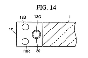
- FIG. 14 is a view showing a backlight unit according to a fifth embodiment of the present invention.
- a difference of the fifth embodiment from the first embodiment is that arrangement of three fluorescent tubes arranged on the inside of the reflector is different. Since other configurations are basically similar to the first embodiment, their illustration and explanation of the same portions are omitted.
- the red color fluorescent tube 13 R, the green color fluorescent tube 13 G, and the blue color fluorescent tube 13 B are arranged on the inside of the reflector 12 .
- the green color fluorescent tube 13 G is arranged at the position closest to the end surface in a longitudinal direction of the light guide plate 1
- the red color fluorescent tube 13 R and the blue color fluorescent tube 13 B are arranged at the position remote from the end surface in a longitudinal direction of the light guide plate 1 to be aligned in the vertical direction.
- These fluorescent tubes 13 R, 13 G, 13 B are connected to the lighting circuits (where three sets of the luminous intensity adjusting circuits and the transformers are employed respectively) shown in FIG. 3, and a quantity of light from them can be adjusted independently.
- the cylindrical green color filter 20 is provided around the green color fluorescent tube 13 G. As indicated by the dot-dash line curve a in FIG. 6, this color filter 20 has the characteristic that cuts off the light whose wavelength is less than about 500 nm and the light whose wavelength is more than about 600 nm. In this case, in the fifth embodiment, the color filter 20 is not essential, and may be added appropriately according to the desired characteristic or the configuration of the light source.
- the green color fluorescent tube 13 G is arranged in the neighborhood of the end surface in a longitudinal direction of the light guide plate 1 , and also the red color fluorescent tube 13 R and the blue color fluorescent tube 13 B, that generate the prominent red and blue color lights on the screen, are arranged at the position remote from the side surface of the light guide plate 1 .
- the red color fluorescent tube 13 R and the blue color fluorescent tube 13 B that generate the prominent red and blue color lights on the screen.
- the present invention is not limited to such cases.
- the present invention can be applied to a backlight unit in which the fluorescent tubes are arranged on the back surface side of the light guide plate.
Abstract
Description
Claims (12)
Applications Claiming Priority (2)
| Application Number | Priority Date | Filing Date | Title |
|---|---|---|---|
| JP2000-171776 | 2000-06-08 | ||
| JP2000171776A JP2001351425A (en) | 2000-06-08 | 2000-06-08 | Backlight device and liquid crystal display device |
Publications (2)
| Publication Number | Publication Date |
|---|---|
| US20010052955A1 US20010052955A1 (en) | 2001-12-20 |
| US6672733B2 true US6672733B2 (en) | 2004-01-06 |
Family
ID=18674288
Family Applications (1)
| Application Number | Title | Priority Date | Filing Date |
|---|---|---|---|
| US09/867,821 Expired - Lifetime US6672733B2 (en) | 2000-06-08 | 2001-05-30 | Backlight unit and liquid crystal device using backlight units |
Country Status (2)
| Country | Link |
|---|---|
| US (1) | US6672733B2 (en) |
| JP (1) | JP2001351425A (en) |
Cited By (16)
| Publication number | Priority date | Publication date | Assignee | Title |
|---|---|---|---|---|
| US20040109664A1 (en) * | 2002-07-26 | 2004-06-10 | Advanced Display Inc. | Planar light source device and liquid crystal display device using the same |
| US20040239839A1 (en) * | 2003-06-02 | 2004-12-02 | Hyung-Ki Hong | Liquid crystal display and method and apparatus for driving the same |
| US20050024847A1 (en) * | 2003-08-02 | 2005-02-03 | Seung-Ho Ahn | Backlight assembly and liquid crystal display apparatus having the same |
| US20050094961A1 (en) * | 2003-10-31 | 2005-05-05 | Hon Hai Precision Industry Co., Ltd. | Light guide plate and back light system using same |
| US20050141217A1 (en) * | 2003-12-30 | 2005-06-30 | Kim Ki D. | LCD device and method of driving the LCD device |
| US20050213311A1 (en) * | 2002-07-04 | 2005-09-29 | Hea-Chun Lee | Back light assembly and liquid crystal display device having the same |
| US20050269560A1 (en) * | 2004-06-02 | 2005-12-08 | Sony Corporation | Illuminating device and liquid crystal display device |
| US20060007705A1 (en) * | 2001-12-28 | 2006-01-12 | Sharp Kabushiki Kaisha | Backlight apparatus, and a liquid crystal display (LCD) therewith |
| US20060273731A1 (en) * | 2005-06-06 | 2006-12-07 | Tbt Asset Management International Limited | High Power Cold Cathode Tubular Fluorescent Lamp |
| US20070041182A1 (en) * | 2005-07-20 | 2007-02-22 | Shichao Ge | Fluorescent Lamp for Lighting Applications |
| US20070081780A1 (en) * | 2003-09-11 | 2007-04-12 | Koninklijke Philips Electronics, N.V. | Lamp system |
| US20080074882A1 (en) * | 2006-09-25 | 2008-03-27 | Jin-Sing Chou | Light source device structure |
| US20090115342A1 (en) * | 2007-11-02 | 2009-05-07 | Victor Lam | Lighting System for Illumination Using Cold Cathode Fluorescent Lamps |
| US20100085289A1 (en) * | 2008-10-08 | 2010-04-08 | Dell Products, Lp | Grayscale-based field-sequential display for low power operation |
| US20100156959A1 (en) * | 2008-12-24 | 2010-06-24 | Sony Corporation | Lighting apparatus and method, display apparatus and method, and program |
| US20100320929A1 (en) * | 2007-11-02 | 2010-12-23 | Victor Lam | Lighting fixture system for illumination using cold cathode fluorescent lamps |
Families Citing this family (24)
| Publication number | Priority date | Publication date | Assignee | Title |
|---|---|---|---|---|
| JP4558874B2 (en) * | 1999-12-17 | 2010-10-06 | ティーピーオー ホンコン ホールディング リミテッド | Lighting device for display device |
| JP3893533B2 (en) * | 2001-02-09 | 2007-03-14 | 株式会社日立製作所 | Liquid crystal display |
| JP4792665B2 (en) * | 2001-06-18 | 2011-10-12 | ソニー株式会社 | Light source control device and method, and projection display device |
| JP4115715B2 (en) * | 2002-03-01 | 2008-07-09 | シャープ株式会社 | Backlight device |
| JP2004163902A (en) * | 2002-08-30 | 2004-06-10 | Mitsubishi Chemicals Corp | Color liquid crystal display device and photosensitive color resin composition |
| CN100365481C (en) * | 2002-11-01 | 2008-01-30 | 广辉电子股份有限公司 | Back light module |
| KR20040041940A (en) * | 2002-11-12 | 2004-05-20 | 삼성전자주식회사 | Liquid crystal display and driving method thereof |
| JP2004166820A (en) | 2002-11-18 | 2004-06-17 | Aruze Corp | Game machine |
| JP2004166963A (en) * | 2002-11-20 | 2004-06-17 | Aruze Corp | Game machine |
| US8096867B2 (en) | 2002-11-20 | 2012-01-17 | Universal Entertainment Corporation | Gaming machine and display device with fail-tolerant image displaying |
| US7972206B2 (en) | 2002-11-20 | 2011-07-05 | Wms Gaming Inc. | Gaming machine and display device therefor |
| JP2004166962A (en) | 2002-11-20 | 2004-06-17 | Aruze Corp | Game machine |
| US7892094B2 (en) | 2003-05-14 | 2011-02-22 | Universal Entertainment Corporation | Gaming machine with a light guiding plate subjected to a light scattering process and having a light deflection pattern |
| JP4655465B2 (en) * | 2003-10-06 | 2011-03-23 | カシオ計算機株式会社 | Surface light source and liquid crystal display device |
| KR20060012959A (en) * | 2004-08-05 | 2006-02-09 | 삼성전자주식회사 | Back light for display device |
| JP4016213B2 (en) * | 2005-05-11 | 2007-12-05 | ソニー株式会社 | Liquid crystal display device and electronic device |
| WO2007078752A2 (en) | 2005-12-19 | 2007-07-12 | Wms Gaming Inc. | Multigame gaming machine with transmissive display |
| US20100165013A1 (en) * | 2006-02-09 | 2010-07-01 | Kazuhisa Yamamoto | Liquid crystal display device |
| JP2008017945A (en) | 2006-07-11 | 2008-01-31 | Aruze Corp | Game machine, and game controlling method |
| US7677777B2 (en) * | 2007-02-21 | 2010-03-16 | Magna International, Inc. | LED apparatus for world homologation |
| WO2008143291A1 (en) * | 2007-05-22 | 2008-11-27 | Sharp Kabushiki Kaisha | Illumination device and display device using the same |
| US8172666B2 (en) | 2008-04-01 | 2012-05-08 | Aruze Gaming America, Inc. | Slot machine |
| JP5725987B2 (en) | 2011-06-13 | 2015-05-27 | キヤノン株式会社 | Light source device |
| JP2017116682A (en) * | 2015-12-24 | 2017-06-29 | カシオ計算機株式会社 | Projection device |
Citations (3)
| Publication number | Priority date | Publication date | Assignee | Title |
|---|---|---|---|---|
| JPH07301797A (en) | 1994-05-06 | 1995-11-14 | Hitachi Ltd | Liquid crystal display device |
| US5976686A (en) * | 1997-10-24 | 1999-11-02 | 3M Innovative Properties Company | Diffuse reflective articles |
| US6196691B1 (en) * | 1998-04-01 | 2001-03-06 | Shimada Precision, Co., Ltd. | Light guide plate for point source |
-
2000
- 2000-06-08 JP JP2000171776A patent/JP2001351425A/en active Pending
-
2001
- 2001-05-30 US US09/867,821 patent/US6672733B2/en not_active Expired - Lifetime
Patent Citations (3)
| Publication number | Priority date | Publication date | Assignee | Title |
|---|---|---|---|---|
| JPH07301797A (en) | 1994-05-06 | 1995-11-14 | Hitachi Ltd | Liquid crystal display device |
| US5976686A (en) * | 1997-10-24 | 1999-11-02 | 3M Innovative Properties Company | Diffuse reflective articles |
| US6196691B1 (en) * | 1998-04-01 | 2001-03-06 | Shimada Precision, Co., Ltd. | Light guide plate for point source |
Cited By (30)
| Publication number | Priority date | Publication date | Assignee | Title |
|---|---|---|---|---|
| US20060007705A1 (en) * | 2001-12-28 | 2006-01-12 | Sharp Kabushiki Kaisha | Backlight apparatus, and a liquid crystal display (LCD) therewith |
| US20050213311A1 (en) * | 2002-07-04 | 2005-09-29 | Hea-Chun Lee | Back light assembly and liquid crystal display device having the same |
| US7473018B2 (en) * | 2002-07-04 | 2009-01-06 | Samsung Electronics Co., Ltd. | Back light assembly and liquid crystal display device having the same |
| US20040109664A1 (en) * | 2002-07-26 | 2004-06-10 | Advanced Display Inc. | Planar light source device and liquid crystal display device using the same |
| US6976779B2 (en) * | 2002-07-26 | 2005-12-20 | Advanced Display Inc. | Planar light source device and liquid crystal display device using the same |
| US7336325B2 (en) * | 2003-06-02 | 2008-02-26 | Lg.Philips Lcd Co., Ltd. | Liquid crystal display and method and apparatus for driving the same comprising of color filters and colored backlights |
| US20040239839A1 (en) * | 2003-06-02 | 2004-12-02 | Hyung-Ki Hong | Liquid crystal display and method and apparatus for driving the same |
| US7241040B2 (en) * | 2003-08-02 | 2007-07-10 | Samsung Electronics Co., Ltd. | Backlight assembly and liquid crystal display apparatus having the same |
| US20050024847A1 (en) * | 2003-08-02 | 2005-02-03 | Seung-Ho Ahn | Backlight assembly and liquid crystal display apparatus having the same |
| US20070081780A1 (en) * | 2003-09-11 | 2007-04-12 | Koninklijke Philips Electronics, N.V. | Lamp system |
| US7441934B2 (en) * | 2003-09-11 | 2008-10-28 | Koninklijke Philips Electronics N.V. | Lamp system |
| US20050094961A1 (en) * | 2003-10-31 | 2005-05-05 | Hon Hai Precision Industry Co., Ltd. | Light guide plate and back light system using same |
| US7292767B2 (en) * | 2003-10-31 | 2007-11-06 | Hon Hai Precision Industry Co., Ltd. | Light guide plate and back light system using same |
| US20050141217A1 (en) * | 2003-12-30 | 2005-06-30 | Kim Ki D. | LCD device and method of driving the LCD device |
| US7850337B2 (en) * | 2003-12-30 | 2010-12-14 | Lg Display Co., Ltd. | LCD device and method of driving the LCD device |
| US7810979B2 (en) * | 2004-06-02 | 2010-10-12 | Sony Corporation | Illuminating device with primary color LED and fluorescent light sources, and liquid crystal display device |
| US20050269560A1 (en) * | 2004-06-02 | 2005-12-08 | Sony Corporation | Illuminating device and liquid crystal display device |
| US20060273731A1 (en) * | 2005-06-06 | 2006-12-07 | Tbt Asset Management International Limited | High Power Cold Cathode Tubular Fluorescent Lamp |
| US7862201B2 (en) | 2005-07-20 | 2011-01-04 | Tbt Asset Management International Limited | Fluorescent lamp for lighting applications |
| US20070041182A1 (en) * | 2005-07-20 | 2007-02-22 | Shichao Ge | Fluorescent Lamp for Lighting Applications |
| US20110156609A1 (en) * | 2005-07-20 | 2011-06-30 | Tbt Asset Management International Limited | Fluorescent lamp for lighting applications |
| US20080074882A1 (en) * | 2006-09-25 | 2008-03-27 | Jin-Sing Chou | Light source device structure |
| US20090115342A1 (en) * | 2007-11-02 | 2009-05-07 | Victor Lam | Lighting System for Illumination Using Cold Cathode Fluorescent Lamps |
| US20100320929A1 (en) * | 2007-11-02 | 2010-12-23 | Victor Lam | Lighting fixture system for illumination using cold cathode fluorescent lamps |
| US7973489B2 (en) | 2007-11-02 | 2011-07-05 | Tbt Asset Management International Limited | Lighting system for illumination using cold cathode fluorescent lamps |
| US8492991B2 (en) | 2007-11-02 | 2013-07-23 | Tbt Asset Management International Limited | Lighting fixture system for illumination using cold cathode fluorescent lamps |
| US20100085289A1 (en) * | 2008-10-08 | 2010-04-08 | Dell Products, Lp | Grayscale-based field-sequential display for low power operation |
| US8466864B2 (en) | 2008-10-08 | 2013-06-18 | Dell Products, Lp | Grayscale-based field-sequential display for low power operation |
| US8884857B2 (en) | 2008-10-08 | 2014-11-11 | Dell Products, Lp | Grayscale-based field-sequential display for low power operation |
| US20100156959A1 (en) * | 2008-12-24 | 2010-06-24 | Sony Corporation | Lighting apparatus and method, display apparatus and method, and program |
Also Published As
| Publication number | Publication date |
|---|---|
| JP2001351425A (en) | 2001-12-21 |
| US20010052955A1 (en) | 2001-12-20 |
Similar Documents
| Publication | Publication Date | Title |
|---|---|---|
| US6672733B2 (en) | Backlight unit and liquid crystal device using backlight units | |
| US20070139957A1 (en) | LED backlight system for LCD displays | |
| US6243068B1 (en) | Liquid crystal flat panel display with enhanced backlight brightness and specially selected light sources | |
| US7789527B2 (en) | Backlight device and color liquid crystal display | |
| US6050704A (en) | Liquid crystal device including backlight lamps having different spectral characteristics for adjusting display color and method of adjusting display color | |
| US6111622A (en) | Day/night backlight for a liquid crystal display | |
| TWI305594B (en) | ||
| US20020006044A1 (en) | Assembly of a display device and an illumination system | |
| JP2001135118A (en) | Panel light source device and flat display using the same | |
| US20060245209A1 (en) | Hybrid backlight apparatus | |
| WO2006040937A1 (en) | Light source unit for backlight, backlight device for liquid crystal display, and transmissive liquid crystal display device | |
| JP4572687B2 (en) | Backlight device and liquid crystal display device | |
| JP2005352426A (en) | Back light device and liquid crystal display device | |
| US7810979B2 (en) | Illuminating device with primary color LED and fluorescent light sources, and liquid crystal display device | |
| JP2006236701A (en) | Backlight device and liquid crystal display | |
| US7850337B2 (en) | LCD device and method of driving the LCD device | |
| KR20040056765A (en) | Backlight unit assembly | |
| JPH06138459A (en) | Light source for plane display panel | |
| JP4760048B2 (en) | Backlight device and liquid crystal display device | |
| KR20050112905A (en) | Method for control brightness of backlight unit | |
| RU2447469C2 (en) | Liquid crystal display | |
| WO2006019076A1 (en) | Backlight device for liquid crystal display and transmissive liquid crystal display | |
| JP2006284906A (en) | Backlight device and liquid crystal display device | |
| JP2006310163A (en) | Strut, backlight device using this strut, and liquid crystal display | |
| CN101663703A (en) | Lighting system and display device equipped with the same |
Legal Events
| Date | Code | Title | Description |
|---|---|---|---|
| AS | Assignment |
Owner name: FUJITSU LIMITED, JAPAN Free format text: ASSIGNMENT OF ASSIGNORS INTEREST;ASSIGNOR:NAGATANI, SHINPEI;REEL/FRAME:011861/0934 Effective date: 20010521 |
|
| AS | Assignment |
Owner name: FUJITSU DISPLAY TECHNOLOGIES CORPORATION, JAPAN Free format text: ASSIGNMENT OF ASSIGNORS INTEREST;ASSIGNOR:FUJITSU LIMITED;REEL/FRAME:013552/0107 Effective date: 20021024 Owner name: FUJITSU DISPLAY TECHNOLOGIES CORPORATION,JAPAN Free format text: ASSIGNMENT OF ASSIGNORS INTEREST;ASSIGNOR:FUJITSU LIMITED;REEL/FRAME:013552/0107 Effective date: 20021024 |
|
| STCF | Information on status: patent grant |
Free format text: PATENTED CASE |
|
| CC | Certificate of correction | ||
| FEPP | Fee payment procedure |
Free format text: PAYOR NUMBER ASSIGNED (ORIGINAL EVENT CODE: ASPN); ENTITY STATUS OF PATENT OWNER: LARGE ENTITY |
|
| AS | Assignment |
Owner name: FUJITSU LIMITED,JAPAN Free format text: ASSIGNMENT OF ASSIGNORS INTEREST;ASSIGNOR:FUJITSU DISPLAY TECHNOLOGIES CORPORATION;REEL/FRAME:016345/0310 Effective date: 20050630 Owner name: FUJITSU LIMITED, JAPAN Free format text: ASSIGNMENT OF ASSIGNORS INTEREST;ASSIGNOR:FUJITSU DISPLAY TECHNOLOGIES CORPORATION;REEL/FRAME:016345/0310 Effective date: 20050630 |
|
| AS | Assignment |
Owner name: SHARP KABUSHIKI KAISHA,JAPAN Free format text: ASSIGNMENT OF ASSIGNORS INTEREST;ASSIGNOR:FUJITSU LIMITED;REEL/FRAME:016345/0210 Effective date: 20050701 Owner name: SHARP KABUSHIKI KAISHA, JAPAN Free format text: ASSIGNMENT OF ASSIGNORS INTEREST;ASSIGNOR:FUJITSU LIMITED;REEL/FRAME:016345/0210 Effective date: 20050701 |
|
| FPAY | Fee payment |
Year of fee payment: 4 |
|
| FPAY | Fee payment |
Year of fee payment: 8 |
|
| FEPP | Fee payment procedure |
Free format text: PAYER NUMBER DE-ASSIGNED (ORIGINAL EVENT CODE: RMPN); ENTITY STATUS OF PATENT OWNER: LARGE ENTITY Free format text: PAYOR NUMBER ASSIGNED (ORIGINAL EVENT CODE: ASPN); ENTITY STATUS OF PATENT OWNER: LARGE ENTITY |
|
| FPAY | Fee payment |
Year of fee payment: 12 |