US6655561B2 - Device comprising a removable sliding central console - Google Patents
Device comprising a removable sliding central console Download PDFInfo
- Publication number
- US6655561B2 US6655561B2 US10/108,264 US10826402A US6655561B2 US 6655561 B2 US6655561 B2 US 6655561B2 US 10826402 A US10826402 A US 10826402A US 6655561 B2 US6655561 B2 US 6655561B2
- Authority
- US
- United States
- Prior art keywords
- support
- console
- carriage
- respect
- rail
- Prior art date
- Legal status (The legal status is an assumption and is not a legal conclusion. Google has not performed a legal analysis and makes no representation as to the accuracy of the status listed.)
- Expired - Lifetime, expires
Links
Images


Classifications
-
- B—PERFORMING OPERATIONS; TRANSPORTING
- B60—VEHICLES IN GENERAL
- B60R—VEHICLES, VEHICLE FITTINGS, OR VEHICLE PARTS, NOT OTHERWISE PROVIDED FOR
- B60R11/00—Arrangements for holding or mounting articles, not otherwise provided for
-
- B—PERFORMING OPERATIONS; TRANSPORTING
- B60—VEHICLES IN GENERAL
- B60N—SEATS SPECIALLY ADAPTED FOR VEHICLES; VEHICLE PASSENGER ACCOMMODATION NOT OTHERWISE PROVIDED FOR
- B60N2/00—Seats specially adapted for vehicles; Arrangement or mounting of seats in vehicles
- B60N2/75—Arm-rests
- B60N2/763—Arm-rests adjustable
- B60N2/773—Longitudinal adjustment
-
- B—PERFORMING OPERATIONS; TRANSPORTING
- B60—VEHICLES IN GENERAL
- B60N—SEATS SPECIALLY ADAPTED FOR VEHICLES; VEHICLE PASSENGER ACCOMMODATION NOT OTHERWISE PROVIDED FOR
- B60N2/00—Seats specially adapted for vehicles; Arrangement or mounting of seats in vehicles
- B60N2/75—Arm-rests
- B60N2/79—Adaptations for additional use of the arm-rests
- B60N2/793—Adaptations for additional use of the arm-rests for use as storage compartments
-
- B—PERFORMING OPERATIONS; TRANSPORTING
- B60—VEHICLES IN GENERAL
- B60R—VEHICLES, VEHICLE FITTINGS, OR VEHICLE PARTS, NOT OTHERWISE PROVIDED FOR
- B60R7/00—Stowing or holding appliances inside vehicle primarily intended for personal property smaller than suit-cases, e.g. travelling articles, or maps
- B60R7/04—Stowing or holding appliances inside vehicle primarily intended for personal property smaller than suit-cases, e.g. travelling articles, or maps in driver or passenger space, e.g. using racks
-
- B—PERFORMING OPERATIONS; TRANSPORTING
- B60—VEHICLES IN GENERAL
- B60R—VEHICLES, VEHICLE FITTINGS, OR VEHICLE PARTS, NOT OTHERWISE PROVIDED FOR
- B60R11/00—Arrangements for holding or mounting articles, not otherwise provided for
- B60R2011/0001—Arrangements for holding or mounting articles, not otherwise provided for characterised by position
- B60R2011/0003—Arrangements for holding or mounting articles, not otherwise provided for characterised by position inside the vehicle
- B60R2011/0007—Mid-console
-
- B—PERFORMING OPERATIONS; TRANSPORTING
- B60—VEHICLES IN GENERAL
- B60R—VEHICLES, VEHICLE FITTINGS, OR VEHICLE PARTS, NOT OTHERWISE PROVIDED FOR
- B60R11/00—Arrangements for holding or mounting articles, not otherwise provided for
- B60R2011/0042—Arrangements for holding or mounting articles, not otherwise provided for characterised by mounting means
- B60R2011/0049—Arrangements for holding or mounting articles, not otherwise provided for characterised by mounting means for non integrated articles
- B60R2011/005—Connection with the vehicle part
- B60R2011/0061—Connection with the vehicle part using key-type connections
-
- B—PERFORMING OPERATIONS; TRANSPORTING
- B60—VEHICLES IN GENERAL
- B60R—VEHICLES, VEHICLE FITTINGS, OR VEHICLE PARTS, NOT OTHERWISE PROVIDED FOR
- B60R11/00—Arrangements for holding or mounting articles, not otherwise provided for
- B60R2011/0042—Arrangements for holding or mounting articles, not otherwise provided for characterised by mounting means
- B60R2011/008—Adjustable or movable supports
- B60R2011/0084—Adjustable or movable supports with adjustment by linear movement in their operational position
Definitions
- the present invention concerns a device for the passenger compartment of a motor vehicle comprising a central console.
- Such a device intended to be arranged between the seats, in particular between the front seats, serves especially for storage or support.
- the document CA-A-2 245 311 describes such a device, comprising in addition to the central console a support intended to be fixed to the passenger compartment of the vehicle and guide means comprising a first portion maintained with respect to the central console and a second portion maintained with respect to the support, said portions being intended to slide relative to each other, and the one defining a rail forming a slideway and the other a carriage forming a slider.
- the central console is not intended to be removed from the passenger compartment of the vehicle, thus reducing its functionality.
- FR-A-2 789 641 discloses a device further comprising releasable connection means disposed between the second portion of the guide means and the support. Said means have an active position in which they maintain the second portion of the guide means with respect to the support and an inactive position in which they release the assembly formed by the console and the guide means with respect to the support.
- the console can not only slide but also be removed. Then only the support remains in place, constituted by the floor of the vehicle, such that there is no risk of damaging either the rail or the carriage. In addition, it is possible to place objects or to move easily in the area freed by the console.
- the assembly has the following features:
- the rail is disposed between the carriage and the console, such that the releasable connection means maintain the carriage with respect to the support,
- the support has a hollow form intended to receive the carriage
- the device further comprises a flap intended to close off the hollow formed in the support when the assembly formed by the console, the rail and the carriage is away from the support.
- the useful volume of the central console is increased, the support being able in fact to be advantageously embedded in a wall of the passenger compartment such as the floor.
- the carriage may be of greater thickness without reducing the useful volume of the central console, thus making it possible to increase the robustness of the device and/or the length of slide.
- the hollow form of the support facilitates the installation of the console by inserting the carriage into said hollow. Finally, once covered by the flap, the support is integrated perfectly into the passenger compartment.
- the device includes position indexing means comprising:
- an indexing rod connected to the carriage and controlled by an electric actuator displacing it between an active position in which it is inserted into the openings of the rib and an inactive position in which it allows sliding between the carriage and the rail,
- control button connected to the actuator and intended to enable the user to allow or prevent sliding of the console with respect to the support.
- a sliding bolt movable between an inactive position in which it provides an access opening to the seatings and an active position in which it closes off said seatings, in order to retain said retaining lugs in said seatings.
- the invention proposes that the releasable connection means comprise control means which allow the release of the console with respect to the support only in a specific relative position of said console with respect to said support.
- the rail be produced from aluminium alloy. It will thus be relatively light, able to incorporate reinforcing elements such as ribs, and exhibit little variation of dimensions without significant extra cost.
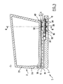
- FIG. 1 shows in an exploded perspective view a device according to the invention
- FIG. 2 shows the device of FIG. 1 in section along the transverse plane II—II in FIG. 3,
- FIG. 3 shows, in section along the plane III—III in FIG. 2, the device according to the invention with the central console in a forward position
- FIG. 4 shows in a similar manner to FIG. 3 the device according to the invention with the central console in a rearward position
- FIG. 5 shows in a similar manner to FIG. 3 the device according to the invention with the central console removed.
- the device 1 of the invention essentially comprises a central console 2 , guide means 4 and a support 10 which are disposed in the passenger compartment 5 of a motor vehicle and are intended to be fixed to the floor 3 of said vehicle.
- the guide means comprise a rail 6 and a carriage 8 , otherwise respectively termed generically a slideway 6 and a slider 8 .
- the rail 6 and the carriage 8 here form an assembly that cannot be dismantled.
- the rail 6 has two longitudinal grooves 12 a , 12 b extending along its lateral ends in each of which run rollers 14 connected to the carriage 8 by way of bearings, in this case needle bearings 15 .
- said rail 6 has a longitudinal rib 16 pierced by a series of transverse holes 18 intended to receive a locking rod 20 , the movement of which is controlled by an electric actuator 22 .
- the actuator 22 has not been shown in those figures.
- the rail 6 advantageously made of profiled aluminium alloy, extends substantially over the entire length of the console and is fixed underneath it by way of screws 24 .
- the carriage 8 itself is intended to be received in the hollow formed by the support 10 . It is removably connected to said support by way of lugs 26 , six in number in this case.
- the retaining lugs 26 of the carriage are terminated by tubular protuberances 28 maintained by a locking plate 32 forming a sliding bolt in seatings 30 provided in the support 10 .
- the locking plate 32 has openings 34 of section substantially similar to that of the seatings 30 and slides with respect to the support 10 between an active position illustrated in FIGS. 1 to 3 and an inactive (retracted) position.
- the openings 34 are offset with respect to the seatings 30 , such that the plate 32 closes off the seatings 30 .
- the locking sliding bolt 32 is in the inactive position, as illustrated in FIGS. 4 and 5, the openings 34 are disposed opposite the seatings 30 , thus releasing the protuberances 28 and consequently the assembly 7 formed by the console 2 , the rail 6 and the carriage 8 (FIG. 5 ).
- the movement of the locking plate 32 between its active position and its inactive position is controlled by way of a pull 36 .
- the pull 36 disposed within the seating 10 , is hidden beneath the rail 6 and the console 2 , such that said console 2 cannot be separated from the support 10 .
- the console 2 by sliding the console 2 into the extreme rearward position, illustrated in FIG. 4, the user has access to said pull 36 .
- the user actuates a control button 38 which supplies the actuator 22 electrically by way of an electrically conducting sheet 40 (illustrated by dash/dotted lines) folded back onto itself in order to follow the relative movement between the console on which the control button 38 is fixed and the carriage 8 on which the actuator 22 is fixed.
- the actuator 22 then causes the withdrawal of the locking rod 20 .
- the user releases the control button 38 and the locking rod 20 is inserted into one of the holes 18 of the rail 6 .
- the device further comprises a flap 46 intended to cover the support 10 when the assembly 7 formed by the console and the guide means 4 are removed, as illustrated in FIG. 5 .
- the floor 3 is then substantially flat, the top of the flap being located substantially at the same level as the floor covering 42 .
- the carriage 8 is advantageously produced from plastics material exhibiting good mechanical qualities, such as acrylonitrile butadiene styrene (ABS) or polyamide (PA), or from metallic material.
- ABS acrylonitrile butadiene styrene
- PA polyamide
- the carriage 8 generally has a length of about 10 to 15 centimeters and a guide length provided by the rollers 14 of approximately 10 to 15 centimeters.
- the rail 6 itself has a length of about 40 to 60 centimeters, like the central console 2 .
Abstract
Description
Claims (7)
Applications Claiming Priority (2)
| Application Number | Priority Date | Filing Date | Title |
|---|---|---|---|
| FR0104355 | 2001-03-30 | ||
| FR0104355A FR2822770B1 (en) | 2001-03-30 | 2001-03-30 | DEVICE INCLUDING A REMOVABLE SLIDING CENTER CONSOLE |
Publications (2)
| Publication Number | Publication Date |
|---|---|
| US20020139824A1 US20020139824A1 (en) | 2002-10-03 |
| US6655561B2 true US6655561B2 (en) | 2003-12-02 |
Family
ID=8861761
Family Applications (1)
| Application Number | Title | Priority Date | Filing Date |
|---|---|---|---|
| US10/108,264 Expired - Lifetime US6655561B2 (en) | 2001-03-30 | 2002-03-28 | Device comprising a removable sliding central console |
Country Status (5)
| Country | Link |
|---|---|
| US (1) | US6655561B2 (en) |
| EP (1) | EP1245447B1 (en) |
| DE (1) | DE60200528T2 (en) |
| ES (1) | ES2220881T3 (en) |
| FR (1) | FR2822770B1 (en) |
Cited By (19)
| Publication number | Priority date | Publication date | Assignee | Title |
|---|---|---|---|---|
| US20050082860A1 (en) * | 2003-10-16 | 2005-04-21 | Ts Tech Co., Ltd. | Center console |
| US20050082861A1 (en) * | 2003-10-16 | 2005-04-21 | Ts Tech Co., Ltd. | Center console |
| US20050116488A1 (en) * | 2003-10-31 | 2005-06-02 | Toyoda Gosei Co., Ltd. | Installation structure for console module |
| US20060131910A1 (en) * | 2004-12-17 | 2006-06-22 | Lear Corporation | Sliding Console |
| US20060237981A1 (en) * | 2005-04-01 | 2006-10-26 | Lisa Draxlmaier Gmbh | Interior components of motor vehicles |
| US20070046058A1 (en) * | 2005-08-29 | 2007-03-01 | Bryan Busha | Removable storage console |
| US20070075107A1 (en) * | 2003-03-05 | 2007-04-05 | Christian Brancheriau | Set comprising a base and a console which is slideable and extractable in relation to the base and correspondng motor vehicle |
| US20070170828A1 (en) * | 2004-01-30 | 2007-07-26 | Thk Co,, Ltd | Movable body driving device and automatic drawer equipment |
| US20080007079A1 (en) * | 2006-07-10 | 2008-01-10 | Lear Corporation | Console assembly for a vehicle |
| US20080079278A1 (en) * | 2006-08-30 | 2008-04-03 | Ramakrishnan Rajappa | Dual Sliding Center Console |
| US20080257923A1 (en) * | 2006-11-09 | 2008-10-23 | Collins & Aikman Corporation | Storage System For Motor Vehicles |
| US20080290680A1 (en) * | 2007-05-24 | 2008-11-27 | Bryan Busha | Sliding console |
| US20080303302A1 (en) * | 2007-06-08 | 2008-12-11 | Lear Corporation | Vehicle Console Assembly |
| US7481475B1 (en) | 2007-10-01 | 2009-01-27 | Toyota Motor Engineering & Manufacturing North America, Inc. | Console assembly for an automotive vehicle |
| US20110068598A1 (en) * | 2009-09-22 | 2011-03-24 | Toyota Motor Engineering & Manufacturing North America, Inc. | Sliding console with lock assembly |
| US20110147425A1 (en) * | 2009-12-23 | 2011-06-23 | Consolidated Edison Company Of New York, Inc. | Vehicle equipment mount |
| US9789824B1 (en) | 2016-07-07 | 2017-10-17 | Ford Global Technologies, Llc | Rotatable center console compartment of a vehicle having customizable subcompartments |
| US10150421B2 (en) * | 2015-11-30 | 2018-12-11 | Faurecia Interieur Industrie | Sliding console, range of consoles, corresponding manufacturing process |
| US11008059B2 (en) * | 2017-04-03 | 2021-05-18 | Lisa Draeximaier GmbH | Mounting system for tool-free mounting of a centre console in a motor vehicle |
Families Citing this family (19)
| Publication number | Priority date | Publication date | Assignee | Title |
|---|---|---|---|---|
| FR2855118A1 (en) * | 2003-05-23 | 2004-11-26 | Renault Sa | SLIDING CONSOLE SYSTEM |
| FR2855117B1 (en) * | 2003-05-23 | 2006-05-12 | Renault Sa | CONSOLE FOR VEHICLE COCKPIT |
| FR2855119B1 (en) * | 2003-05-23 | 2005-07-15 | Renault Sa | ASSEMBLY METHOD AND GUIDE ASSEMBLY OF A MOBILE CONSOLE |
| FR2864492B1 (en) * | 2003-12-24 | 2006-03-24 | Faurecia Interieur Ind | EXTRACTIBLE CONSOLE ASSEMBLY WITH SLIDING LOCK MEANS AND CORRESPONDING MOTOR VEHICLE |
| DE602004007127T2 (en) * | 2004-07-21 | 2008-02-28 | Euramax Industries S.A. | Guide device for a movable unit |
| FR2886241B1 (en) | 2005-05-27 | 2007-08-03 | Euramax Ind Sa Sa | SLIDING ASSEMBLY FOR A VEHICLE |
| FR2889121B1 (en) | 2005-07-28 | 2007-10-19 | Euramax Ind Sa Sa | SLIDING EMSEMBLE AND SLIDING FURNITURE ASSEMBLY FOR A VEHICLE |
| FR2901204B1 (en) * | 2006-05-16 | 2008-08-22 | Faurecia Interieur Ind Snc | CONSOLE FOR STORING OBJECTS FOR A MOTOR VEHICLE, MOTOR VEHICLE, AND ASSOCIATED ASSEMBLY METHOD |
| DE102006031098A1 (en) * | 2006-07-05 | 2008-01-10 | GM Global Technology Operations, Inc., Detroit | Vehicle-sided device for assembly of e.g. clamping belt, has brackets with recesses or projections for accommodating fastening unit or accommodation units, where brackets are directly connected, welded or bolted with substructure of vehicle |
| US7401831B2 (en) * | 2006-09-19 | 2008-07-22 | International Automotive Components Group North America, Inc. | Slidable floor console |
| FR2920710B1 (en) * | 2007-09-12 | 2009-10-09 | Heuliez Sa | SLIDING MECHANISM ON A VEHICLE |
| DE102011008586B4 (en) * | 2011-01-14 | 2013-09-05 | Audi Ag | Device for the displaceable mounting of objects in a motor vehicle |
| DE102011118150A1 (en) * | 2011-11-10 | 2013-05-16 | Gm Global Technology Operations, Llc | Storage of a functional element in a pair of rails within a passenger compartment of a motor vehicle |
| FR3030401B1 (en) * | 2014-12-22 | 2018-09-07 | Renault S.A.S. | "CENTER CONSOLE FOR A MOTOR VEHICLE HAVING SUPPORTING MEANS" |
| FR3030400B1 (en) * | 2014-12-22 | 2017-01-13 | Renault Sa | "CENTER CONSOLE FOR A MOTOR VEHICLE" |
| US10703235B2 (en) * | 2018-04-30 | 2020-07-07 | Ford Global Technologies, Llc | Slideably releasable center console |
| CN109050414A (en) * | 2018-07-10 | 2018-12-21 | 上海延锋金桥汽车饰件系统有限公司 | A kind of vehicle mounted electric sliding rail |
| CN110040047B (en) * | 2019-04-10 | 2020-07-10 | 东风汽车集团有限公司 | Sliding stop structure |
| CN111231793B (en) * | 2020-03-24 | 2020-11-03 | 桂林电子科技大学 | Adjustable truck quick-assembly central armrest |
Citations (10)
| Publication number | Priority date | Publication date | Assignee | Title |
|---|---|---|---|---|
| US2576385A (en) * | 1949-10-01 | 1951-11-27 | Robert L Bigsby | Extensible storage compartment for automobiles |
| US3004678A (en) * | 1959-06-25 | 1961-10-17 | Theodore S Golaski | Multi-purpose cargo carrier |
| US4146159A (en) | 1977-12-05 | 1979-03-27 | Hemmen Alan J | Slidable automobile storage arm rest |
| US4303367A (en) * | 1979-05-15 | 1981-12-01 | Bott John Anthony | Automobile shopping bag container |
| US4705315A (en) * | 1986-10-10 | 1987-11-10 | Cherry Kim N | Slidable storage container |
| DE29611382U1 (en) | 1996-06-29 | 1997-12-11 | Illies Gmbh, 38667 Bad Harzburg, De | LUGGAGE BOX FOR MOTOR VEHICLES |
| CA2245311A1 (en) | 1997-08-19 | 1999-02-19 | Atoma International Inc. | Multi-position sliding center console with adjustable table top |
| FR2789641A1 (en) | 1999-02-12 | 2000-08-18 | Allibert Ind | Console for inserting between two front car seats has fixed base, attached to car floor, and detachable section linked together via lateral translation between slides and notch |
| US6203088B1 (en) * | 1999-01-19 | 2001-03-20 | Johnson Controls Technology Company' | Sliding console system |
| US6416143B1 (en) * | 1999-06-09 | 2002-07-09 | Spacesaver Corporation | Mobile storage system |
-
2001
- 2001-03-30 FR FR0104355A patent/FR2822770B1/en not_active Expired - Fee Related
-
2002
- 2002-03-28 US US10/108,264 patent/US6655561B2/en not_active Expired - Lifetime
- 2002-03-28 ES ES02290781T patent/ES2220881T3/en not_active Expired - Lifetime
- 2002-03-28 DE DE60200528T patent/DE60200528T2/en not_active Expired - Lifetime
- 2002-03-28 EP EP02290781A patent/EP1245447B1/en not_active Expired - Lifetime
Patent Citations (11)
| Publication number | Priority date | Publication date | Assignee | Title |
|---|---|---|---|---|
| US2576385A (en) * | 1949-10-01 | 1951-11-27 | Robert L Bigsby | Extensible storage compartment for automobiles |
| US3004678A (en) * | 1959-06-25 | 1961-10-17 | Theodore S Golaski | Multi-purpose cargo carrier |
| US4146159A (en) | 1977-12-05 | 1979-03-27 | Hemmen Alan J | Slidable automobile storage arm rest |
| US4303367A (en) * | 1979-05-15 | 1981-12-01 | Bott John Anthony | Automobile shopping bag container |
| US4705315A (en) * | 1986-10-10 | 1987-11-10 | Cherry Kim N | Slidable storage container |
| DE29611382U1 (en) | 1996-06-29 | 1997-12-11 | Illies Gmbh, 38667 Bad Harzburg, De | LUGGAGE BOX FOR MOTOR VEHICLES |
| CA2245311A1 (en) | 1997-08-19 | 1999-02-19 | Atoma International Inc. | Multi-position sliding center console with adjustable table top |
| US6135529A (en) * | 1997-08-19 | 2000-10-24 | Atoma International Inc. | Multi-position sliding center console |
| US6203088B1 (en) * | 1999-01-19 | 2001-03-20 | Johnson Controls Technology Company' | Sliding console system |
| FR2789641A1 (en) | 1999-02-12 | 2000-08-18 | Allibert Ind | Console for inserting between two front car seats has fixed base, attached to car floor, and detachable section linked together via lateral translation between slides and notch |
| US6416143B1 (en) * | 1999-06-09 | 2002-07-09 | Spacesaver Corporation | Mobile storage system |
Cited By (27)
| Publication number | Priority date | Publication date | Assignee | Title |
|---|---|---|---|---|
| US20070075107A1 (en) * | 2003-03-05 | 2007-04-05 | Christian Brancheriau | Set comprising a base and a console which is slideable and extractable in relation to the base and correspondng motor vehicle |
| US20050082861A1 (en) * | 2003-10-16 | 2005-04-21 | Ts Tech Co., Ltd. | Center console |
| US20050082860A1 (en) * | 2003-10-16 | 2005-04-21 | Ts Tech Co., Ltd. | Center console |
| US7007993B2 (en) * | 2003-10-16 | 2006-03-07 | Ts Tech Co., Ltd. | Center console |
| US7007994B2 (en) * | 2003-10-16 | 2006-03-07 | Ts Tech Co., Ltd. | Center console |
| US7185937B2 (en) * | 2003-10-31 | 2007-03-06 | Toyoda Gosei Co., Ltd. | Installation structure for console module |
| US20050116488A1 (en) * | 2003-10-31 | 2005-06-02 | Toyoda Gosei Co., Ltd. | Installation structure for console module |
| US20070170828A1 (en) * | 2004-01-30 | 2007-07-26 | Thk Co,, Ltd | Movable body driving device and automatic drawer equipment |
| US7156438B2 (en) * | 2004-12-17 | 2007-01-02 | Lear Corporation | Sliding console |
| US20060131910A1 (en) * | 2004-12-17 | 2006-06-22 | Lear Corporation | Sliding Console |
| US20060237981A1 (en) * | 2005-04-01 | 2006-10-26 | Lisa Draxlmaier Gmbh | Interior components of motor vehicles |
| US7475930B2 (en) * | 2005-04-01 | 2009-01-13 | Lisa Dräxlmaier GmbH | Interior components of motor vehicles |
| US20070046058A1 (en) * | 2005-08-29 | 2007-03-01 | Bryan Busha | Removable storage console |
| US7429068B2 (en) | 2005-08-29 | 2008-09-30 | Irvin Automotive Products, Inc. | Removable storage console |
| US20080007079A1 (en) * | 2006-07-10 | 2008-01-10 | Lear Corporation | Console assembly for a vehicle |
| US7416235B2 (en) * | 2006-08-30 | 2008-08-26 | Chrysler Llc | Dual sliding center console |
| US20080079278A1 (en) * | 2006-08-30 | 2008-04-03 | Ramakrishnan Rajappa | Dual Sliding Center Console |
| US20080257923A1 (en) * | 2006-11-09 | 2008-10-23 | Collins & Aikman Corporation | Storage System For Motor Vehicles |
| US20080290680A1 (en) * | 2007-05-24 | 2008-11-27 | Bryan Busha | Sliding console |
| US7591498B2 (en) | 2007-05-24 | 2009-09-22 | Irvin Automotive Products, Inc. | Sliding console |
| US20080303302A1 (en) * | 2007-06-08 | 2008-12-11 | Lear Corporation | Vehicle Console Assembly |
| US7481475B1 (en) | 2007-10-01 | 2009-01-27 | Toyota Motor Engineering & Manufacturing North America, Inc. | Console assembly for an automotive vehicle |
| US20110068598A1 (en) * | 2009-09-22 | 2011-03-24 | Toyota Motor Engineering & Manufacturing North America, Inc. | Sliding console with lock assembly |
| US20110147425A1 (en) * | 2009-12-23 | 2011-06-23 | Consolidated Edison Company Of New York, Inc. | Vehicle equipment mount |
| US10150421B2 (en) * | 2015-11-30 | 2018-12-11 | Faurecia Interieur Industrie | Sliding console, range of consoles, corresponding manufacturing process |
| US9789824B1 (en) | 2016-07-07 | 2017-10-17 | Ford Global Technologies, Llc | Rotatable center console compartment of a vehicle having customizable subcompartments |
| US11008059B2 (en) * | 2017-04-03 | 2021-05-18 | Lisa Draeximaier GmbH | Mounting system for tool-free mounting of a centre console in a motor vehicle |
Also Published As
| Publication number | Publication date |
|---|---|
| DE60200528D1 (en) | 2004-07-01 |
| FR2822770B1 (en) | 2003-08-15 |
| US20020139824A1 (en) | 2002-10-03 |
| ES2220881T3 (en) | 2004-12-16 |
| EP1245447A1 (en) | 2002-10-02 |
| FR2822770A1 (en) | 2002-10-04 |
| EP1245447B1 (en) | 2004-05-26 |
| DE60200528T2 (en) | 2005-06-23 |
Similar Documents
| Publication | Publication Date | Title |
|---|---|---|
| US6655561B2 (en) | Device comprising a removable sliding central console | |
| US20190232830A1 (en) | Vehicle Seat | |
| US20090058154A1 (en) | Vehicle seat assembly | |
| US20090072565A1 (en) | Vehicle console assembly | |
| US8459731B2 (en) | Head restraint and seat stow flat handle | |
| US7481478B2 (en) | Combination type cargo screen movable front and rear | |
| US7216916B2 (en) | Flipper panel for a vehicle | |
| US20010013570A1 (en) | Vehicle seat slide device | |
| US9937824B2 (en) | Vehicle seat adjustment system | |
| US20120049559A1 (en) | Vehicle seat storage compartment | |
| US6361086B1 (en) | Mechanical latch | |
| EP1132252B1 (en) | Vehicle seat slide device | |
| JP3704578B2 (en) | Slide rail structure for vehicle seat | |
| US4354695A (en) | Seat belt system | |
| EP1205368B1 (en) | Parking brake control lever | |
| US8079564B2 (en) | Mechanism for locking the rails of a motor vehicle seat | |
| GB2450548A (en) | A retaining arrangement | |
| JP2000318528A (en) | Slide-type tonneau cover for automobile | |
| CN218367522U (en) | Back-unlocked seat headrest | |
| KR970004075Y1 (en) | Footrest for a vehicle | |
| JPH0349936Y2 (en) | ||
| JP4528060B2 (en) | Car | |
| JPH0270542A (en) | Seat slide device with memory | |
| JP3040992U (en) | Console Box | |
| JPH0649230Y2 (en) | Rear seat device for automobile |
Legal Events
| Date | Code | Title | Description |
|---|---|---|---|
| AS | Assignment |
Owner name: SAI AUTOMATIVE ALLIBERT INDUSTRIE, FRANCE Free format text: ASSIGNMENT OF ASSIGNORS INTEREST;ASSIGNORS:PANHELLEUX, JEROME;MARCEAU, THIERRY;FEYEL, MARIE-CLAIRE;AND OTHERS;REEL/FRAME:012939/0241 Effective date: 20020515 |
|
| STCF | Information on status: patent grant |
Free format text: PATENTED CASE |
|
| FEPP | Fee payment procedure |
Free format text: PAYER NUMBER DE-ASSIGNED (ORIGINAL EVENT CODE: RMPN); ENTITY STATUS OF PATENT OWNER: LARGE ENTITY Free format text: PAYOR NUMBER ASSIGNED (ORIGINAL EVENT CODE: ASPN); ENTITY STATUS OF PATENT OWNER: LARGE ENTITY |
|
| FPAY | Fee payment |
Year of fee payment: 4 |
|
| FPAY | Fee payment |
Year of fee payment: 8 |
|
| FPAY | Fee payment |
Year of fee payment: 12 |