US6647038B2 - Optoelectronic laser module - Google Patents
Optoelectronic laser module Download PDFInfo
- Publication number
- US6647038B2 US6647038B2 US09/970,441 US97044101A US6647038B2 US 6647038 B2 US6647038 B2 US 6647038B2 US 97044101 A US97044101 A US 97044101A US 6647038 B2 US6647038 B2 US 6647038B2
- Authority
- US
- United States
- Prior art keywords
- fiber
- module according
- optical
- grating
- housing
- Prior art date
- Legal status (The legal status is an assumption and is not a legal conclusion. Google has not performed a legal analysis and makes no representation as to the accuracy of the status listed.)
- Expired - Lifetime
Links
Images


Classifications
-
- H—ELECTRICITY
- H01—ELECTRIC ELEMENTS
- H01S—DEVICES USING THE PROCESS OF LIGHT AMPLIFICATION BY STIMULATED EMISSION OF RADIATION [LASER] TO AMPLIFY OR GENERATE LIGHT; DEVICES USING STIMULATED EMISSION OF ELECTROMAGNETIC RADIATION IN WAVE RANGES OTHER THAN OPTICAL
- H01S5/00—Semiconductor lasers
- H01S5/02—Structural details or components not essential to laser action
- H01S5/022—Mountings; Housings
- H01S5/0225—Out-coupling of light
- H01S5/02251—Out-coupling of light using optical fibres
-
- G—PHYSICS
- G02—OPTICS
- G02B—OPTICAL ELEMENTS, SYSTEMS OR APPARATUS
- G02B6/00—Light guides; Structural details of arrangements comprising light guides and other optical elements, e.g. couplings
- G02B6/24—Coupling light guides
- G02B6/42—Coupling light guides with opto-electronic elements
- G02B6/4201—Packages, e.g. shape, construction, internal or external details
- G02B6/4204—Packages, e.g. shape, construction, internal or external details the coupling comprising intermediate optical elements, e.g. lenses, holograms
- G02B6/4215—Packages, e.g. shape, construction, internal or external details the coupling comprising intermediate optical elements, e.g. lenses, holograms the intermediate optical elements being wavelength selective optical elements, e.g. variable wavelength optical modules or wavelength lockers
-
- G—PHYSICS
- G02—OPTICS
- G02B—OPTICAL ELEMENTS, SYSTEMS OR APPARATUS
- G02B6/00—Light guides; Structural details of arrangements comprising light guides and other optical elements, e.g. couplings
- G02B6/24—Coupling light guides
- G02B6/42—Coupling light guides with opto-electronic elements
- G02B6/4201—Packages, e.g. shape, construction, internal or external details
- G02B6/4219—Mechanical fixtures for holding or positioning the elements relative to each other in the couplings; Alignment methods for the elements, e.g. measuring or observing methods especially used therefor
- G02B6/4236—Fixing or mounting methods of the aligned elements
- G02B6/4244—Mounting of the optical elements
-
- H—ELECTRICITY
- H01—ELECTRIC ELEMENTS
- H01S—DEVICES USING THE PROCESS OF LIGHT AMPLIFICATION BY STIMULATED EMISSION OF RADIATION [LASER] TO AMPLIFY OR GENERATE LIGHT; DEVICES USING STIMULATED EMISSION OF ELECTROMAGNETIC RADIATION IN WAVE RANGES OTHER THAN OPTICAL
- H01S5/00—Semiconductor lasers
- H01S5/10—Construction or shape of the optical resonator, e.g. extended or external cavity, coupled cavities, bent-guide, varying width, thickness or composition of the active region
- H01S5/14—External cavity lasers
- H01S5/146—External cavity lasers using a fiber as external cavity
- H01S5/147—External cavity lasers using a fiber as external cavity having specially shaped fibre, e.g. lensed or tapered end portion
-
- G—PHYSICS
- G02—OPTICS
- G02B—OPTICAL ELEMENTS, SYSTEMS OR APPARATUS
- G02B6/00—Light guides; Structural details of arrangements comprising light guides and other optical elements, e.g. couplings
- G02B6/24—Coupling light guides
- G02B6/36—Mechanical coupling means
- G02B6/38—Mechanical coupling means having fibre to fibre mating means
- G02B6/3807—Dismountable connectors, i.e. comprising plugs
- G02B6/3833—Details of mounting fibres in ferrules; Assembly methods; Manufacture
- G02B6/3845—Details of mounting fibres in ferrules; Assembly methods; Manufacture ferrules comprising functional elements, e.g. filters
-
- G—PHYSICS
- G02—OPTICS
- G02B—OPTICAL ELEMENTS, SYSTEMS OR APPARATUS
- G02B6/00—Light guides; Structural details of arrangements comprising light guides and other optical elements, e.g. couplings
- G02B6/24—Coupling light guides
- G02B6/42—Coupling light guides with opto-electronic elements
- G02B6/4201—Packages, e.g. shape, construction, internal or external details
- G02B6/4204—Packages, e.g. shape, construction, internal or external details the coupling comprising intermediate optical elements, e.g. lenses, holograms
- G02B6/4207—Packages, e.g. shape, construction, internal or external details the coupling comprising intermediate optical elements, e.g. lenses, holograms with optical elements reducing the sensitivity to optical feedback
-
- G—PHYSICS
- G02—OPTICS
- G02B—OPTICAL ELEMENTS, SYSTEMS OR APPARATUS
- G02B6/00—Light guides; Structural details of arrangements comprising light guides and other optical elements, e.g. couplings
- G02B6/24—Coupling light guides
- G02B6/42—Coupling light guides with opto-electronic elements
- G02B6/4201—Packages, e.g. shape, construction, internal or external details
- G02B6/4256—Details of housings
- G02B6/4262—Details of housings characterised by the shape of the housing
- G02B6/4263—Details of housings characterised by the shape of the housing of the transisitor outline [TO] can type
-
- G—PHYSICS
- G02—OPTICS
- G02B—OPTICAL ELEMENTS, SYSTEMS OR APPARATUS
- G02B6/00—Light guides; Structural details of arrangements comprising light guides and other optical elements, e.g. couplings
- G02B6/24—Coupling light guides
- G02B6/42—Coupling light guides with opto-electronic elements
- G02B6/4201—Packages, e.g. shape, construction, internal or external details
- G02B6/4285—Optical modules characterised by a connectorised pigtail
-
- H—ELECTRICITY
- H01—ELECTRIC ELEMENTS
- H01S—DEVICES USING THE PROCESS OF LIGHT AMPLIFICATION BY STIMULATED EMISSION OF RADIATION [LASER] TO AMPLIFY OR GENERATE LIGHT; DEVICES USING STIMULATED EMISSION OF ELECTROMAGNETIC RADIATION IN WAVE RANGES OTHER THAN OPTICAL
- H01S5/00—Semiconductor lasers
- H01S5/02—Structural details or components not essential to laser action
- H01S5/022—Mountings; Housings
- H01S5/0225—Out-coupling of light
- H01S5/02255—Out-coupling of light using beam deflecting elements
-
- H—ELECTRICITY
- H01—ELECTRIC ELEMENTS
- H01S—DEVICES USING THE PROCESS OF LIGHT AMPLIFICATION BY STIMULATED EMISSION OF RADIATION [LASER] TO AMPLIFY OR GENERATE LIGHT; DEVICES USING STIMULATED EMISSION OF ELECTROMAGNETIC RADIATION IN WAVE RANGES OTHER THAN OPTICAL
- H01S5/00—Semiconductor lasers
- H01S5/10—Construction or shape of the optical resonator, e.g. extended or external cavity, coupled cavities, bent-guide, varying width, thickness or composition of the active region
- H01S5/1039—Details on the cavity length
-
- H—ELECTRICITY
- H01—ELECTRIC ELEMENTS
- H01S—DEVICES USING THE PROCESS OF LIGHT AMPLIFICATION BY STIMULATED EMISSION OF RADIATION [LASER] TO AMPLIFY OR GENERATE LIGHT; DEVICES USING STIMULATED EMISSION OF ELECTROMAGNETIC RADIATION IN WAVE RANGES OTHER THAN OPTICAL
- H01S5/00—Semiconductor lasers
- H01S5/40—Arrangement of two or more semiconductor lasers, not provided for in groups H01S5/02 - H01S5/30
- H01S5/4025—Array arrangements, e.g. constituted by discrete laser diodes or laser bar
- H01S5/4087—Array arrangements, e.g. constituted by discrete laser diodes or laser bar emitting more than one wavelength
Definitions
- the invention relates to an optoelectronic laser module having a laser diode with an active region, an optical resonator with a highly silvered reflecting surface and a Bragg interference grating that provides frequency-selective feedback.
- a housing accommodates the laser diode and has a holder for coupling an optical conductor.
- Such a laser module is suitable, in particular, for use in dense wavelength division multiplex (DWDM) systems.
- DWDM dense wavelength division multiplex
- DBR distributed Bragg reflector
- a fiber Bragg grating into an optical fiber.
- a reflective index is increased in specific regions of the fiber core of an optical fiber, for example by punctiform illumination of the fiber or by using a phase mask that generates an interference fringe pattern in the optical fiber.
- Current methods for generating a fiber Bragg grating are described in a reference by K. O. Hill et al. titled “Fiber Bragg Grating Technology Fundamentals and Overview”, Journal of Lightwave Technology, Vol. 15, No. 8, August 1997, pages 1263-1276.
- an optoelectronic laser module contains a laser diode having an active region and a highly silvered reflecting surface, and an optical conductor having a Bragg interference grating providing frequency-selective feedback.
- the highly silvered reflecting surface and the Bragg interference grating form an optical resonator, the Bragg interference grating functioning as a fiber Bragg grating in the optical conductor.
- a housing is provided for accommodating the laser diode, the housing has a holder coupling the optical conductor.
- the invention is distinguished in that the Bragg interference grating in the optical conductor is configured as a fiber Bragg grating, and the optical conductor is connected to the housing containing the laser diode via a holder. Because of the construction of the interference grating in the optical conductor to be coupled to the laser diode, the invention provides a laser having an external resonator, an external cavity laser (ECL). In this case, a desired wavelength of the laser diode can be set precisely by suitable selection of the grating period of the fiber Bragg grating.
- ECL external cavity laser
- the pluggable optical conductor by changing the pluggable optical conductor it is possible to provide a fiber Bragg grating having a different desired grating period which leads to a changed emission wavelength of the laser diode.
- the invention therefore permits in a simple way a setting or a selection of the emission wavelength of a laser diode, without the need to change the actual configuration of the laser diode.
- the structure according to the invention has the advantage that a very stable single-mode operation of the semiconductor laser is ensured in the case of use of quartz glass as the optical conductor material.
- quartz glass the change in wavelength per Kelvin is approximately ten times smaller. Again, a larger effective wavelength is present because of the use of an external resonator.
- the module is therefore rendered more insensitive to temperature changes and to changes in the optical properties of the laser diode.
- the module has a coupling optical system between the optical conductor and the laser diode.
- the coupling optical system preferably contains a high-index coupling lens with a focal length of preferably less than one millimeter.
- the coupling lens is, in particular, a spherical or aspherical silicon lens, GaP lens, SiC lens or a lens made from another suitable high-index optical material.
- a glass lens with a particularly short focal length in particular a glass aspheric.
- the laser diode advantageously has a rear facet that is coated with a highly reflecting layer and constitutes the highly silvered reflecting surface of the resonator.
- a front facet of the laser diode is, by contrast, preferably coated with an antireflection layer which has a residual reflection of less than 0.1%, such that parasitic resonances of the optical resonator are suppressed.
- Light is emitted to the fiber Bragg grating or received thereby via the front facet, and so reflection at this facet is not desired.
- the front facet is aligned slightly inclined to the optical axis of the laser diode, in particular at an angle of approximately 1° to 5°. This reduces undesired feedback owing to back reflections at other structures than the fiber Bragg grating.
- the optical conductor is preferably embedded in a cylindrical ferrule that can be plugged into the holder of the housing.
- the ferrule can be part of a fiber plug connector that can be pluggably connected to the housing.
- the optical conductor can be connected to a fiber plug connector in another way than via a ferrule.
- the ferrule or the fiber plug connector can preferably be detachably connected to the housing such that the emission wavelength of the module can be changed by simply changing the optical conductor and providing an optical conductor with a different grating period.
- the housing preferably has a cylindrical holder for an optical conductor.
- the cylindrical holder serves to hold and couple a cylindrical ferrule that contains the optical conductor with fiber Bragg grating.
- the housing preferably has a coaxial geometry, and is preferably a TO housing.
- An external cavity laser with a stabilized wavelength is provided in a very cost-effective way by the use of a standard component such as a TO housing into which there is preferably plugged as a pigtail a standard fiber plug connector which only additionally has one fiber Bragg grating.
- the optical conductor is preferably a single-mode glass fiber, the fiber Bragg grating being located in the glass fiber directly downstream of the end face or facet of the glass fiber.
- the light launched into the glass fiber immediately strikes the Bragg reflector and is consequently immediately fed back in a wavelength-selective fashion. It is possible in this case to use standard glass fibers and glass fiber plug connectors for connecting the glass fiber to the housing of the laser module, a fiber Bragg grating being inscribed into the standard glass fiber.
- the end face of the glass fiber is preferably chamfered in order to avoid undesired feedback to other structures than the fiber Bragg grating.
- the length of the optical resonator is preferably so short that the circulation frequency of the light is above a desired modulation frequency of the module. Otherwise, it would not be possible to transmit information on the optical information channel provided by the laser.
- the length of the optical resonator is preferably less than ten millimeters.
- the module according to the invention has a plurality of laser diodes, optical resonators and fiber Bragg gratings which are respectively constructed in an optical conductor, the spatial grating period of the individual fiber Bragg gratings differing for each optical conductor in such a way that light of a different wavelength is launched in each case.
- This provides a module with a multiplicity of optical channels such as is applied in DWDM systems, in particular. In this case, typically more than 40 channels with channel spacings of 100 GHz are implemented in a dense wavelength division multiplex.
- FIG. 1 is a diagrammatic, sectional view of a laser module according to the invention
- FIG. 2 is a sectional view of a second embodiment of the laser module
- FIG. 3 is a sectional view of a third embodiment of the laser module
- FIG. 4 is a perspective view of a laser diode of the laser module.
- FIG. 1 there is shown a laser module according to the invention that has a laser chip 1 which is disposed on a TO base 2 of a TO housing 5 .
- the TO housing 5 has a cylindrical coaxial geometry and forms a holder 51 into which it is possible to plug a glass fiber 8 surrounded by a ferrule 6 for the purpose of optical coupling.
- the TO base 2 or the laser chip 1 disposed thereon is driven and supplied electrically via electric connections 3 which lead away from the TO base 2 .
- TO housings are standard housings, known in the prior art, for optical transmit or receive modules, the form of which resembles the housing of a standard transistor, but which have an opening on the topside for the entry or exit of light.
- a TO laser module in the case of which a glass fiber is coupled to the TO laser module, is also designated as a coaxial module.
- the coupled glass fiber is also designated as a pigtail.
- a facet or end face 81 of the glass fiber 8 is located in accordance with FIG. 1 in the interior of the housing 5 , and is coupled optically to the laser chip 1 via a coupling optical system.
- the coupling optical system has a deflecting mirror 9 and a lens 4 located in a holder, which deflect light emitted by the laser chip 1 onto the end face of the glass fiber 8 , or vice versa, and thereby couple the laser light from the laser diode 1 into the glass fiber 8 .
- the laser chip 1 is a Fabry-Perot semiconductor laser chip and is illustrated schematically in FIG. 4 . Accordingly, the chip 1 has in a way known per se a cuboid crystal volume with an active laser region 15 which is bounded by two plane-parallel crystal faces or facets 12 , 13 .
- the rear facet 12 of the laser chip 1 is provided with a highly reflecting layer, and constitutes a reflecting surface. The rear facet 12 can be assigned a monitor diode in this case (not illustrated).
- the front facet 13 is antireflection-coated, and so laser light 14 passes the front facet 13 without reflections and is launched into the glass fiber 8 via the coupling optical system 9 , 4 (compare FIG. 1 ).
- the residual reflections reach values below 0.1% in this case.
- the front and the rear facets of the laser chip 1 are slightly tilted with respect to the laser axis, in order to avoid undesired reflections and resonances.
- the grating period of the grating 7 is selected in such a way that only a desired wavelength ⁇ is retroreflected.
- a typical spatial grating period is approximately 0.5 ⁇ m.
- the optical resonator of the laser is formed by the rear, silvered facet 12 of the laser chip 1 and the fiber grating 7 of the optical conductor 8 .
- the fiber grating 7 provides frequency-selective feedback of the light emitted by the active region 15 of the laser chip 1 , such that only the reflected frequency is amplified and emitted as laser light. A portion of the laser light is transmitted in this case into the optical fiber 8 through the fiber Bragg grating 7 .
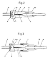
- FIG. 2 A second exemplary embodiment of the invention is illustrated in FIG. 2 . Identical elements are denoted in this case with identical reference numerals.
- the ferrule 6 which surrounds the optical conductor 8 , is permanently connected to the housing 5 of the optoelectronic module.
- a plastic sleeve 10 bearing against the holder 51 of the housing 5 ensures in this case that the optical conductor 8 cannot be bent too strongly.
- the lens 4 is a silicon lens with a short focal length of preferably less than two, in particular less than one millimeter.
- the numerical aperture of the lens 4 is sufficiently large and is typically above the value of 0.4.
- the silicon lens was produced, for example, from a planar substrate via etched structures. Alternatively, it is also possible to use other spherical or aspherical lenses made from a suitable optical material for the respective wavelength region, for example made from glass, plastic, GaP or SiC.
- the refractive index of the lens is preferably greater than 2 in this case.
- An end face 81 ′ of the glass fiber 8 is slightly chamfered in order to avoid undesired back reflections.
- the chamfering is typically 8°, it also being possible for larger or smaller angles, in particular between 5° and 25°, to be implemented, depending on the application.
- FIG. 3 shows the module according to the invention, in the case of which the optical conductor 8 can be pluggably coupled to the housing 5 of the laser module.
- the holder of the housing 5 is constructed in this case cylindrically and in such a way that the ferrule 6 need only be pushed into the opening with the optical conductor 8 .
- a screwable fixing element 11 serves a purpose of connecting the ferrule 6 and the glass fiber 8 permanently to the housing 5 .
- another fiber Bragg grating 7 it is possible in this case for another fiber Bragg grating 7 to be provided in a simple way by exchanging the ferrule 6 with the glass fiber 8 and plugging in another glass fiber with a fiber grating of another grating period. Since a different grating period leads to a change in the frequency fed back, the emission wavelength of the laser module can be changed by changing the optical conductor 8 or the fiber grating 7 .
- Experiments have shown that it is possible in this way to use only one laser to generate more than ten different channel wavelengths that, for example, respectively have a spacing of 100 MHz. This is particularly advantageous for providing replacement laser modules in systems with many WDM channels.
- the resonator length of the laser module is selected to be short in such a way that the circulation frequency of the light in the resonator is higher than the desired modulation frequency of the module.
- the resonant frequency is at bit rates of the modulated signal of up to 10 Gbit/s in conjunction with approximately 15 GHz.
- FIG. 5 shows an exemplary embodiment of the module according to the invention in the case of which a multiplicity of laser diodes are disposed in TO housings 5 , and coupled optical fibers 8 , 8 ′, 8 ′′ with fiber Bragg gratings in accordance with FIGS. 1 to 3 are disposed in an array on a carrier plate 16 .
- the spatial grating period of the fiber Bragg grating differs for each optical fiber 8 , 8 ′, 8 ′′, and so the respective laser in each case has a somewhat different emission wavelength, and consequently light of a different wavelength is respectively launched into the individual optical fibers 8 , 8 ′, 8 ′′.
- the result is that through the use of similar laser diodes a module with a multiplicity of optical channels is provided such as is used, in particular, in DWDM systems.
- the individual optical channels in this case preferably have a fixed channel spacing of, for example, 100 GHz.
Landscapes
- Physics & Mathematics (AREA)
- General Physics & Mathematics (AREA)
- Optics & Photonics (AREA)
- Condensed Matter Physics & Semiconductors (AREA)
- Electromagnetism (AREA)
- Optical Couplings Of Light Guides (AREA)
- Semiconductor Lasers (AREA)
Abstract
Description
Claims (14)
Applications Claiming Priority (1)
| Application Number | Priority Date | Filing Date | Title |
|---|---|---|---|
| PCT/DE2001/002262 WO2002103867A1 (en) | 2001-06-15 | 2001-06-15 | Optoelectronic laser module |
Related Parent Applications (1)
| Application Number | Title | Priority Date | Filing Date |
|---|---|---|---|
| PCT/DE2001/002262 Continuation WO2002103867A1 (en) | 2001-06-15 | 2001-06-15 | Optoelectronic laser module |
Publications (2)
| Publication Number | Publication Date |
|---|---|
| US20020196824A1 US20020196824A1 (en) | 2002-12-26 |
| US6647038B2 true US6647038B2 (en) | 2003-11-11 |
Family
ID=5648253
Family Applications (1)
| Application Number | Title | Priority Date | Filing Date |
|---|---|---|---|
| US09/970,441 Expired - Lifetime US6647038B2 (en) | 2001-06-15 | 2001-10-03 | Optoelectronic laser module |
Country Status (2)
| Country | Link |
|---|---|
| US (1) | US6647038B2 (en) |
| WO (1) | WO2002103867A1 (en) |
Cited By (9)
| Publication number | Priority date | Publication date | Assignee | Title |
|---|---|---|---|---|
| US20030123500A1 (en) * | 2001-12-25 | 2003-07-03 | Takeshi Fujita | Optical module |
| US20030210729A1 (en) * | 2002-05-08 | 2003-11-13 | Sumitomo Electric Industries, Ltd. | Multimode light generating module, semiconductor laser apparatus, and optical fiber amplifier |
| US20040264856A1 (en) * | 2003-06-30 | 2004-12-30 | Mina Farr | Micro-module with micro-lens |
| US20050025420A1 (en) * | 2003-06-30 | 2005-02-03 | Mina Farr | Optical sub-assembly laser mount having integrated microlens |
| US20060133729A1 (en) * | 2004-12-20 | 2006-06-22 | Cho Seung H | Method for fabricating laser diode having optical fiber Bragg grating as front mirror of external resonator and laser diode fabricated thereby |
| US20070121689A1 (en) * | 2003-09-22 | 2007-05-31 | Snake Creek Lasers Llc | Methods for Producing Diode-Pumped Micro Lasers |
| US20070166852A1 (en) * | 2003-09-22 | 2007-07-19 | Snake Creek Lasers Llc | Diode-pumped microlasers including resonator microchips and methods for producing the same |
| US20070278194A1 (en) * | 2004-08-05 | 2007-12-06 | Kuka Schweissanlagen Gmbh | Laser Device And Operating Method |
| US20070297469A1 (en) * | 2004-09-28 | 2007-12-27 | Snake Creek Lasers, Llc | Cryogenically Cooled Solid State Lasers |
Families Citing this family (7)
| Publication number | Priority date | Publication date | Assignee | Title |
|---|---|---|---|---|
| JP2007508682A (en) * | 2003-09-22 | 2007-04-05 | スネイク クリーク レーザーズ エルエルシー | High density method for manufacturing diode pumped microlasers |
| CA2502266A1 (en) * | 2004-03-26 | 2005-09-26 | Kyocera Corporation | External resonator and semiconductor laser module using the same |
| US7519091B2 (en) * | 2006-05-25 | 2009-04-14 | National Chiao Tung University | All-optical 2R regenerator using self-seeded laser diode |
| ES2776481T3 (en) * | 2012-10-01 | 2020-07-30 | Hoffmann La Roche | Light source module and procedure for modifying an analytical instrument to analyze a sample |
| CN107078466B (en) * | 2014-12-10 | 2020-01-14 | 特拉迪欧德公司 | Optical cross-coupling suppression system for wavelength beam combining laser system |
| US11362484B2 (en) * | 2017-09-19 | 2022-06-14 | Kyocera Corporation | Light-emitting-element housing member, array member, and light emitting device |
| US20190129108A1 (en) * | 2017-10-31 | 2019-05-02 | Versalume LLC | Modular Laser Connector Packaging System and Method |
Citations (17)
| Publication number | Priority date | Publication date | Assignee | Title |
|---|---|---|---|---|
| US3897135A (en) * | 1972-07-28 | 1975-07-29 | Post Office | Optical communications systems |
| US5181213A (en) * | 1990-07-27 | 1993-01-19 | Pioneer Electronic Corporation | Optical pulse generating apparatus |
| US5305336A (en) | 1992-01-29 | 1994-04-19 | At&T Bell Laboratories | Compact optical pulse source |
| JPH0949948A (en) | 1995-06-01 | 1997-02-18 | Sumitomo Electric Ind Ltd | Array type light emitting element module and its production |
| US5717711A (en) * | 1995-11-21 | 1998-02-10 | Alcatel Optronics | Laser device, notably for optical pumping, and method of fabricating it |
| US5724377A (en) * | 1996-02-29 | 1998-03-03 | Lucent Technologies Inc. | Method and apparatus for improving the instability of a laser |
| US5832011A (en) | 1993-03-25 | 1998-11-03 | British Telecommunications Public Limited Company | Laser |
| US5914972A (en) * | 1997-03-24 | 1999-06-22 | Sdl, Inc. | Thermal compensators for waveguide DBR laser sources |
| JPH11326709A (en) * | 1998-05-13 | 1999-11-26 | Mitsubishi Electric Corp | Laser diode module |
| US5995692A (en) * | 1996-06-19 | 1999-11-30 | Sumitomo Electric Industries, Ltd. | Light emitting device module |
| DE19823691A1 (en) | 1998-05-27 | 1999-12-02 | Siemens Ag | Housing arrangement for laser module |
| EP1059711A2 (en) | 1999-06-10 | 2000-12-13 | Sumitomo Electric Industries, Ltd. | Semiconductor laser module |
| WO2001024324A2 (en) | 1999-09-15 | 2001-04-05 | Sarnoff Corporation | High-power laser with transverse mode filter |
| US6226311B1 (en) * | 1998-04-10 | 2001-05-01 | Agilent Technologies, Inc. | Laser module with external cavity and optical fibre reflector |
| US6273620B1 (en) * | 1998-08-27 | 2001-08-14 | Sumitomo Electric Industries, Ltd. | Semiconductor light emitting module |
| US6278721B1 (en) * | 1999-03-03 | 2001-08-21 | Lucent Technologies, Inc. | Method for minimizing locking range variability of a laser module |
| US6337874B1 (en) * | 1999-05-27 | 2002-01-08 | Corning Lasertron, Inc. | Optical component with polarization-maintaining fiber pigtail splice to regular fiber with grating |
-
2001
- 2001-06-15 WO PCT/DE2001/002262 patent/WO2002103867A1/en active Application Filing
- 2001-10-03 US US09/970,441 patent/US6647038B2/en not_active Expired - Lifetime
Patent Citations (17)
| Publication number | Priority date | Publication date | Assignee | Title |
|---|---|---|---|---|
| US3897135A (en) * | 1972-07-28 | 1975-07-29 | Post Office | Optical communications systems |
| US5181213A (en) * | 1990-07-27 | 1993-01-19 | Pioneer Electronic Corporation | Optical pulse generating apparatus |
| US5305336A (en) | 1992-01-29 | 1994-04-19 | At&T Bell Laboratories | Compact optical pulse source |
| US5832011A (en) | 1993-03-25 | 1998-11-03 | British Telecommunications Public Limited Company | Laser |
| JPH0949948A (en) | 1995-06-01 | 1997-02-18 | Sumitomo Electric Ind Ltd | Array type light emitting element module and its production |
| US5717711A (en) * | 1995-11-21 | 1998-02-10 | Alcatel Optronics | Laser device, notably for optical pumping, and method of fabricating it |
| US5724377A (en) * | 1996-02-29 | 1998-03-03 | Lucent Technologies Inc. | Method and apparatus for improving the instability of a laser |
| US5995692A (en) * | 1996-06-19 | 1999-11-30 | Sumitomo Electric Industries, Ltd. | Light emitting device module |
| US5914972A (en) * | 1997-03-24 | 1999-06-22 | Sdl, Inc. | Thermal compensators for waveguide DBR laser sources |
| US6226311B1 (en) * | 1998-04-10 | 2001-05-01 | Agilent Technologies, Inc. | Laser module with external cavity and optical fibre reflector |
| JPH11326709A (en) * | 1998-05-13 | 1999-11-26 | Mitsubishi Electric Corp | Laser diode module |
| DE19823691A1 (en) | 1998-05-27 | 1999-12-02 | Siemens Ag | Housing arrangement for laser module |
| US6273620B1 (en) * | 1998-08-27 | 2001-08-14 | Sumitomo Electric Industries, Ltd. | Semiconductor light emitting module |
| US6278721B1 (en) * | 1999-03-03 | 2001-08-21 | Lucent Technologies, Inc. | Method for minimizing locking range variability of a laser module |
| US6337874B1 (en) * | 1999-05-27 | 2002-01-08 | Corning Lasertron, Inc. | Optical component with polarization-maintaining fiber pigtail splice to regular fiber with grating |
| EP1059711A2 (en) | 1999-06-10 | 2000-12-13 | Sumitomo Electric Industries, Ltd. | Semiconductor laser module |
| WO2001024324A2 (en) | 1999-09-15 | 2001-04-05 | Sarnoff Corporation | High-power laser with transverse mode filter |
Non-Patent Citations (2)
| Title |
|---|
| Kenneth O. Hill et al.: "Fiber Bragg Grating Technology Fundamentals and Overview", Journal of Lightwave Technology, vol. 15, No. 8, Aug. 1997, pp. 1263-1276. |
| Reinhold Paul: "Optoelektronische Halbleiterbauelemente (optoelectronic semiconductor components)", vol. 2, 1992, pp. 203-204; (No month). |
Cited By (13)
| Publication number | Priority date | Publication date | Assignee | Title |
|---|---|---|---|---|
| US20030123500A1 (en) * | 2001-12-25 | 2003-07-03 | Takeshi Fujita | Optical module |
| US6920158B2 (en) * | 2001-12-25 | 2005-07-19 | Mitsubishi Denki Kabushiki Kaisha | Optical module |
| US20030210729A1 (en) * | 2002-05-08 | 2003-11-13 | Sumitomo Electric Industries, Ltd. | Multimode light generating module, semiconductor laser apparatus, and optical fiber amplifier |
| US6944203B2 (en) * | 2002-05-08 | 2005-09-13 | Sumitomo Electric Industries, Ltd. | Multimode light generating module, semiconductor laser apparatus, and optical fiber amplifier |
| US20040264856A1 (en) * | 2003-06-30 | 2004-12-30 | Mina Farr | Micro-module with micro-lens |
| US20050025420A1 (en) * | 2003-06-30 | 2005-02-03 | Mina Farr | Optical sub-assembly laser mount having integrated microlens |
| US7422377B2 (en) * | 2003-06-30 | 2008-09-09 | Finisar Corporation | Micro-module with micro-lens |
| US20070121689A1 (en) * | 2003-09-22 | 2007-05-31 | Snake Creek Lasers Llc | Methods for Producing Diode-Pumped Micro Lasers |
| US20070166852A1 (en) * | 2003-09-22 | 2007-07-19 | Snake Creek Lasers Llc | Diode-pumped microlasers including resonator microchips and methods for producing the same |
| US20070278194A1 (en) * | 2004-08-05 | 2007-12-06 | Kuka Schweissanlagen Gmbh | Laser Device And Operating Method |
| US20070297469A1 (en) * | 2004-09-28 | 2007-12-27 | Snake Creek Lasers, Llc | Cryogenically Cooled Solid State Lasers |
| US7421164B2 (en) * | 2004-12-20 | 2008-09-02 | Electronics And Telecommunications Research Institute | Method for fabricating laser diode having optical fiber Bragg grating as front mirror of external resonator and laser diode fabricated thereby |
| US20060133729A1 (en) * | 2004-12-20 | 2006-06-22 | Cho Seung H | Method for fabricating laser diode having optical fiber Bragg grating as front mirror of external resonator and laser diode fabricated thereby |
Also Published As
| Publication number | Publication date |
|---|---|
| US20020196824A1 (en) | 2002-12-26 |
| WO2002103867A1 (en) | 2002-12-27 |
Similar Documents
| Publication | Publication Date | Title |
|---|---|---|
| US6647038B2 (en) | Optoelectronic laser module | |
| US9065572B1 (en) | Robustly stabilizing laser systems | |
| US4923270A (en) | Apparatus for optical wavelength division multiplexing | |
| US6572278B2 (en) | Opto-electronic device having staked connection between parts to prevent differential thermal expansion | |
| US5940564A (en) | Device for coupling a light source or receiver to an optical waveguide | |
| US6483635B1 (en) | Apparatus for light amplification | |
| JP2004096009A (en) | Laser package and laser beam source module | |
| US20160261092A1 (en) | Temperature insensitive laser | |
| JP2010251649A (en) | Surface emitting laser module and surface light receiving module | |
| US20030185269A1 (en) | Fiber-coupled vertical-cavity surface emitting laser | |
| US20020146054A1 (en) | Modulatable multi-wavelength semiconductor external cavity laser | |
| US20030072336A1 (en) | Miniaturized internal laser stabilizing apparatus with inline output for fiber optic applications | |
| US6792178B1 (en) | Fiber optic header with integrated power monitor | |
| US6600845B1 (en) | Integrated parallel transmitter | |
| US5243671A (en) | Laser-to-fiber coupling apparatus | |
| US7020366B2 (en) | Light emitting device, optical module, and grating chip | |
| EP0150214A1 (en) | Coupled cavity laser. | |
| JP2001242346A (en) | Multi-fiber array connector system | |
| JP2000183445A (en) | Semiconductor laser module | |
| US6400746B1 (en) | Pump laser with low grating reflectivity | |
| KR19990013585A (en) | Optical communication device and method | |
| Palen | Low cost optical interconnects | |
| JP2000208869A (en) | Light emitting device module | |
| JP3412584B2 (en) | External cavity type semiconductor laser | |
| US6913401B2 (en) | Optical transmitter and optical connector |
Legal Events
| Date | Code | Title | Description |
|---|---|---|---|
| AS | Assignment |
Owner name: INFINEON TECHNOLOGIES AG, GERMANY Free format text: ASSIGNMENT OF ASSIGNORS INTEREST;ASSIGNORS:ALTHAUS, HANS-LUDWIG;ALBRECHT, HELMUT;ROTHHARDT, MANFRED;AND OTHERS;REEL/FRAME:014366/0459;SIGNING DATES FROM 20010905 TO 20010921 |
|
| STCF | Information on status: patent grant |
Free format text: PATENTED CASE |
|
| CC | Certificate of correction | ||
| AS | Assignment |
Owner name: FINISAR CORPORATION,CALIFORNIA Free format text: ASSIGNMENT OF ASSIGNORS INTEREST;ASSIGNOR:INFINEON TECHNOLOGIES AG;REEL/FRAME:017425/0874 Effective date: 20060321 Owner name: FINISAR CORPORATION, CALIFORNIA Free format text: ASSIGNMENT OF ASSIGNORS INTEREST;ASSIGNOR:INFINEON TECHNOLOGIES AG;REEL/FRAME:017425/0874 Effective date: 20060321 |
|
| FPAY | Fee payment |
Year of fee payment: 4 |
|
| FPAY | Fee payment |
Year of fee payment: 8 |
|
| FPAY | Fee payment |
Year of fee payment: 12 |
|
| AS | Assignment |
Owner name: BANK OF AMERICA, N.A., AS ADMINISTRATIVE AGENT, NO Free format text: NOTICE OF GRANT OF SECURITY INTEREST IN PATENTS;ASSIGNORS:II-VI INCORPORATED;MARLOW INDUSTRIES, INC.;EPIWORKS, INC.;AND OTHERS;REEL/FRAME:050484/0204 Effective date: 20190924 Owner name: BANK OF AMERICA, N.A., AS ADMINISTRATIVE AGENT, NORTH CAROLINA Free format text: NOTICE OF GRANT OF SECURITY INTEREST IN PATENTS;ASSIGNORS:II-VI INCORPORATED;MARLOW INDUSTRIES, INC.;EPIWORKS, INC.;AND OTHERS;REEL/FRAME:050484/0204 Effective date: 20190924 |
|
| AS | Assignment |
Owner name: II-VI DELAWARE, INC., DELAWARE Free format text: ASSIGNMENT OF ASSIGNORS INTEREST;ASSIGNOR:FINISAR CORPORATION;REEL/FRAME:052286/0001 Effective date: 20190924 |
|
| AS | Assignment |
Owner name: PHOTOP TECHNOLOGIES, INC., CALIFORNIA Free format text: PATENT RELEASE AND REASSIGNMENT;ASSIGNOR:BANK OF AMERICA, N.A., AS ADMINISTRATIVE AGENT;REEL/FRAME:060574/0001 Effective date: 20220701 Owner name: II-VI OPTOELECTRONIC DEVICES, INC., NEW JERSEY Free format text: PATENT RELEASE AND REASSIGNMENT;ASSIGNOR:BANK OF AMERICA, N.A., AS ADMINISTRATIVE AGENT;REEL/FRAME:060574/0001 Effective date: 20220701 Owner name: II-VI DELAWARE, INC., PENNSYLVANIA Free format text: PATENT RELEASE AND REASSIGNMENT;ASSIGNOR:BANK OF AMERICA, N.A., AS ADMINISTRATIVE AGENT;REEL/FRAME:060574/0001 Effective date: 20220701 Owner name: II-VI PHOTONICS (US), INC., MASSACHUSETTS Free format text: PATENT RELEASE AND REASSIGNMENT;ASSIGNOR:BANK OF AMERICA, N.A., AS ADMINISTRATIVE AGENT;REEL/FRAME:060574/0001 Effective date: 20220701 Owner name: M CUBED TECHNOLOGIES, INC., CONNECTICUT Free format text: PATENT RELEASE AND REASSIGNMENT;ASSIGNOR:BANK OF AMERICA, N.A., AS ADMINISTRATIVE AGENT;REEL/FRAME:060574/0001 Effective date: 20220701 Owner name: II-VI OPTICAL SYSTEMS, INC., CALIFORNIA Free format text: PATENT RELEASE AND REASSIGNMENT;ASSIGNOR:BANK OF AMERICA, N.A., AS ADMINISTRATIVE AGENT;REEL/FRAME:060574/0001 Effective date: 20220701 Owner name: FINISAR CORPORATION, CALIFORNIA Free format text: PATENT RELEASE AND REASSIGNMENT;ASSIGNOR:BANK OF AMERICA, N.A., AS ADMINISTRATIVE AGENT;REEL/FRAME:060574/0001 Effective date: 20220701 Owner name: OPTIUM CORPORATION, CALIFORNIA Free format text: PATENT RELEASE AND REASSIGNMENT;ASSIGNOR:BANK OF AMERICA, N.A., AS ADMINISTRATIVE AGENT;REEL/FRAME:060574/0001 Effective date: 20220701 Owner name: COADNA PHOTONICS, INC., PENNSYLVANIA Free format text: PATENT RELEASE AND REASSIGNMENT;ASSIGNOR:BANK OF AMERICA, N.A., AS ADMINISTRATIVE AGENT;REEL/FRAME:060574/0001 Effective date: 20220701 Owner name: KAILIGHT PHOTONICS, INC., CALIFORNIA Free format text: PATENT RELEASE AND REASSIGNMENT;ASSIGNOR:BANK OF AMERICA, N.A., AS ADMINISTRATIVE AGENT;REEL/FRAME:060574/0001 Effective date: 20220701 Owner name: LIGHTSMYTH TECHNOLOGIES, INC., OREGON Free format text: PATENT RELEASE AND REASSIGNMENT;ASSIGNOR:BANK OF AMERICA, N.A., AS ADMINISTRATIVE AGENT;REEL/FRAME:060574/0001 Effective date: 20220701 Owner name: EPIWORKS, INC., ILLINOIS Free format text: PATENT RELEASE AND REASSIGNMENT;ASSIGNOR:BANK OF AMERICA, N.A., AS ADMINISTRATIVE AGENT;REEL/FRAME:060574/0001 Effective date: 20220701 Owner name: MARLOW INDUSTRIES, INC., TEXAS Free format text: PATENT RELEASE AND REASSIGNMENT;ASSIGNOR:BANK OF AMERICA, N.A., AS ADMINISTRATIVE AGENT;REEL/FRAME:060574/0001 Effective date: 20220701 Owner name: II-VI INCORPORATED, PENNSYLVANIA Free format text: PATENT RELEASE AND REASSIGNMENT;ASSIGNOR:BANK OF AMERICA, N.A., AS ADMINISTRATIVE AGENT;REEL/FRAME:060574/0001 Effective date: 20220701 |