US6638310B2 - Intervertebral spacer and implant insertion instrumentation - Google Patents
Intervertebral spacer and implant insertion instrumentation Download PDFInfo
- Publication number
- US6638310B2 US6638310B2 US09/734,860 US73486000A US6638310B2 US 6638310 B2 US6638310 B2 US 6638310B2 US 73486000 A US73486000 A US 73486000A US 6638310 B2 US6638310 B2 US 6638310B2
- Authority
- US
- United States
- Prior art keywords
- spacer
- intervertebral
- intervertebral spacer
- bone
- spacer according
- Prior art date
- Legal status (The legal status is an assumption and is not a legal conclusion. Google has not performed a legal analysis and makes no representation as to the accuracy of the status listed.)
- Expired - Lifetime, expires
Links
Images


Classifications
-
- A—HUMAN NECESSITIES
- A61—MEDICAL OR VETERINARY SCIENCE; HYGIENE
- A61F—FILTERS IMPLANTABLE INTO BLOOD VESSELS; PROSTHESES; DEVICES PROVIDING PATENCY TO, OR PREVENTING COLLAPSING OF, TUBULAR STRUCTURES OF THE BODY, e.g. STENTS; ORTHOPAEDIC, NURSING OR CONTRACEPTIVE DEVICES; FOMENTATION; TREATMENT OR PROTECTION OF EYES OR EARS; BANDAGES, DRESSINGS OR ABSORBENT PADS; FIRST-AID KITS
- A61F2/00—Filters implantable into blood vessels; Prostheses, i.e. artificial substitutes or replacements for parts of the body; Appliances for connecting them with the body; Devices providing patency to, or preventing collapsing of, tubular structures of the body, e.g. stents
- A61F2/02—Prostheses implantable into the body
- A61F2/30—Joints
- A61F2/44—Joints for the spine, e.g. vertebrae, spinal discs
-
- A—HUMAN NECESSITIES
- A61—MEDICAL OR VETERINARY SCIENCE; HYGIENE
- A61F—FILTERS IMPLANTABLE INTO BLOOD VESSELS; PROSTHESES; DEVICES PROVIDING PATENCY TO, OR PREVENTING COLLAPSING OF, TUBULAR STRUCTURES OF THE BODY, e.g. STENTS; ORTHOPAEDIC, NURSING OR CONTRACEPTIVE DEVICES; FOMENTATION; TREATMENT OR PROTECTION OF EYES OR EARS; BANDAGES, DRESSINGS OR ABSORBENT PADS; FIRST-AID KITS
- A61F2/00—Filters implantable into blood vessels; Prostheses, i.e. artificial substitutes or replacements for parts of the body; Appliances for connecting them with the body; Devices providing patency to, or preventing collapsing of, tubular structures of the body, e.g. stents
- A61F2/02—Prostheses implantable into the body
- A61F2/30—Joints
- A61F2/46—Special tools or methods for implanting or extracting artificial joints, accessories, bone grafts or substitutes, or particular adaptations therefor
- A61F2/4684—Trial or dummy prostheses
-
- A—HUMAN NECESSITIES
- A61—MEDICAL OR VETERINARY SCIENCE; HYGIENE
- A61F—FILTERS IMPLANTABLE INTO BLOOD VESSELS; PROSTHESES; DEVICES PROVIDING PATENCY TO, OR PREVENTING COLLAPSING OF, TUBULAR STRUCTURES OF THE BODY, e.g. STENTS; ORTHOPAEDIC, NURSING OR CONTRACEPTIVE DEVICES; FOMENTATION; TREATMENT OR PROTECTION OF EYES OR EARS; BANDAGES, DRESSINGS OR ABSORBENT PADS; FIRST-AID KITS
- A61F2/00—Filters implantable into blood vessels; Prostheses, i.e. artificial substitutes or replacements for parts of the body; Appliances for connecting them with the body; Devices providing patency to, or preventing collapsing of, tubular structures of the body, e.g. stents
- A61F2/02—Prostheses implantable into the body
- A61F2/28—Bones
-
- A—HUMAN NECESSITIES
- A61—MEDICAL OR VETERINARY SCIENCE; HYGIENE
- A61F—FILTERS IMPLANTABLE INTO BLOOD VESSELS; PROSTHESES; DEVICES PROVIDING PATENCY TO, OR PREVENTING COLLAPSING OF, TUBULAR STRUCTURES OF THE BODY, e.g. STENTS; ORTHOPAEDIC, NURSING OR CONTRACEPTIVE DEVICES; FOMENTATION; TREATMENT OR PROTECTION OF EYES OR EARS; BANDAGES, DRESSINGS OR ABSORBENT PADS; FIRST-AID KITS
- A61F2/00—Filters implantable into blood vessels; Prostheses, i.e. artificial substitutes or replacements for parts of the body; Appliances for connecting them with the body; Devices providing patency to, or preventing collapsing of, tubular structures of the body, e.g. stents
- A61F2/02—Prostheses implantable into the body
- A61F2/30—Joints
- A61F2/44—Joints for the spine, e.g. vertebrae, spinal discs
- A61F2/4455—Joints for the spine, e.g. vertebrae, spinal discs for the fusion of spinal bodies, e.g. intervertebral fusion of adjacent spinal bodies, e.g. fusion cages
-
- A—HUMAN NECESSITIES
- A61—MEDICAL OR VETERINARY SCIENCE; HYGIENE
- A61F—FILTERS IMPLANTABLE INTO BLOOD VESSELS; PROSTHESES; DEVICES PROVIDING PATENCY TO, OR PREVENTING COLLAPSING OF, TUBULAR STRUCTURES OF THE BODY, e.g. STENTS; ORTHOPAEDIC, NURSING OR CONTRACEPTIVE DEVICES; FOMENTATION; TREATMENT OR PROTECTION OF EYES OR EARS; BANDAGES, DRESSINGS OR ABSORBENT PADS; FIRST-AID KITS
- A61F2/00—Filters implantable into blood vessels; Prostheses, i.e. artificial substitutes or replacements for parts of the body; Appliances for connecting them with the body; Devices providing patency to, or preventing collapsing of, tubular structures of the body, e.g. stents
- A61F2/02—Prostheses implantable into the body
- A61F2/30—Joints
- A61F2/46—Special tools or methods for implanting or extracting artificial joints, accessories, bone grafts or substitutes, or particular adaptations therefor
- A61F2/4603—Special tools or methods for implanting or extracting artificial joints, accessories, bone grafts or substitutes, or particular adaptations therefor for insertion or extraction of endoprosthetic joints or of accessories thereof
- A61F2/4611—Special tools or methods for implanting or extracting artificial joints, accessories, bone grafts or substitutes, or particular adaptations therefor for insertion or extraction of endoprosthetic joints or of accessories thereof of spinal prostheses
-
- A—HUMAN NECESSITIES
- A61—MEDICAL OR VETERINARY SCIENCE; HYGIENE
- A61F—FILTERS IMPLANTABLE INTO BLOOD VESSELS; PROSTHESES; DEVICES PROVIDING PATENCY TO, OR PREVENTING COLLAPSING OF, TUBULAR STRUCTURES OF THE BODY, e.g. STENTS; ORTHOPAEDIC, NURSING OR CONTRACEPTIVE DEVICES; FOMENTATION; TREATMENT OR PROTECTION OF EYES OR EARS; BANDAGES, DRESSINGS OR ABSORBENT PADS; FIRST-AID KITS
- A61F2/00—Filters implantable into blood vessels; Prostheses, i.e. artificial substitutes or replacements for parts of the body; Appliances for connecting them with the body; Devices providing patency to, or preventing collapsing of, tubular structures of the body, e.g. stents
- A61F2/02—Prostheses implantable into the body
- A61F2/30—Joints
- A61F2/44—Joints for the spine, e.g. vertebrae, spinal discs
- A61F2/4455—Joints for the spine, e.g. vertebrae, spinal discs for the fusion of spinal bodies, e.g. intervertebral fusion of adjacent spinal bodies, e.g. fusion cages
- A61F2/4465—Joints for the spine, e.g. vertebrae, spinal discs for the fusion of spinal bodies, e.g. intervertebral fusion of adjacent spinal bodies, e.g. fusion cages having a circular or kidney shaped cross-section substantially perpendicular to the axis of the spine
-
- A—HUMAN NECESSITIES
- A61—MEDICAL OR VETERINARY SCIENCE; HYGIENE
- A61F—FILTERS IMPLANTABLE INTO BLOOD VESSELS; PROSTHESES; DEVICES PROVIDING PATENCY TO, OR PREVENTING COLLAPSING OF, TUBULAR STRUCTURES OF THE BODY, e.g. STENTS; ORTHOPAEDIC, NURSING OR CONTRACEPTIVE DEVICES; FOMENTATION; TREATMENT OR PROTECTION OF EYES OR EARS; BANDAGES, DRESSINGS OR ABSORBENT PADS; FIRST-AID KITS
- A61F2/00—Filters implantable into blood vessels; Prostheses, i.e. artificial substitutes or replacements for parts of the body; Appliances for connecting them with the body; Devices providing patency to, or preventing collapsing of, tubular structures of the body, e.g. stents
- A61F2/02—Prostheses implantable into the body
- A61F2/30—Joints
- A61F2/44—Joints for the spine, e.g. vertebrae, spinal discs
- A61F2/4455—Joints for the spine, e.g. vertebrae, spinal discs for the fusion of spinal bodies, e.g. intervertebral fusion of adjacent spinal bodies, e.g. fusion cages
- A61F2/447—Joints for the spine, e.g. vertebrae, spinal discs for the fusion of spinal bodies, e.g. intervertebral fusion of adjacent spinal bodies, e.g. fusion cages substantially parallelepipedal, e.g. having a rectangular or trapezoidal cross-section
-
- A—HUMAN NECESSITIES
- A61—MEDICAL OR VETERINARY SCIENCE; HYGIENE
- A61F—FILTERS IMPLANTABLE INTO BLOOD VESSELS; PROSTHESES; DEVICES PROVIDING PATENCY TO, OR PREVENTING COLLAPSING OF, TUBULAR STRUCTURES OF THE BODY, e.g. STENTS; ORTHOPAEDIC, NURSING OR CONTRACEPTIVE DEVICES; FOMENTATION; TREATMENT OR PROTECTION OF EYES OR EARS; BANDAGES, DRESSINGS OR ABSORBENT PADS; FIRST-AID KITS
- A61F2/00—Filters implantable into blood vessels; Prostheses, i.e. artificial substitutes or replacements for parts of the body; Appliances for connecting them with the body; Devices providing patency to, or preventing collapsing of, tubular structures of the body, e.g. stents
- A61F2/02—Prostheses implantable into the body
- A61F2/28—Bones
- A61F2002/2825—Femur
-
- A—HUMAN NECESSITIES
- A61—MEDICAL OR VETERINARY SCIENCE; HYGIENE
- A61F—FILTERS IMPLANTABLE INTO BLOOD VESSELS; PROSTHESES; DEVICES PROVIDING PATENCY TO, OR PREVENTING COLLAPSING OF, TUBULAR STRUCTURES OF THE BODY, e.g. STENTS; ORTHOPAEDIC, NURSING OR CONTRACEPTIVE DEVICES; FOMENTATION; TREATMENT OR PROTECTION OF EYES OR EARS; BANDAGES, DRESSINGS OR ABSORBENT PADS; FIRST-AID KITS
- A61F2/00—Filters implantable into blood vessels; Prostheses, i.e. artificial substitutes or replacements for parts of the body; Appliances for connecting them with the body; Devices providing patency to, or preventing collapsing of, tubular structures of the body, e.g. stents
- A61F2/02—Prostheses implantable into the body
- A61F2/28—Bones
- A61F2002/2853—Humerus
-
- A—HUMAN NECESSITIES
- A61—MEDICAL OR VETERINARY SCIENCE; HYGIENE
- A61F—FILTERS IMPLANTABLE INTO BLOOD VESSELS; PROSTHESES; DEVICES PROVIDING PATENCY TO, OR PREVENTING COLLAPSING OF, TUBULAR STRUCTURES OF THE BODY, e.g. STENTS; ORTHOPAEDIC, NURSING OR CONTRACEPTIVE DEVICES; FOMENTATION; TREATMENT OR PROTECTION OF EYES OR EARS; BANDAGES, DRESSINGS OR ABSORBENT PADS; FIRST-AID KITS
- A61F2/00—Filters implantable into blood vessels; Prostheses, i.e. artificial substitutes or replacements for parts of the body; Appliances for connecting them with the body; Devices providing patency to, or preventing collapsing of, tubular structures of the body, e.g. stents
- A61F2/02—Prostheses implantable into the body
- A61F2/28—Bones
- A61F2002/2892—Tibia
-
- A—HUMAN NECESSITIES
- A61—MEDICAL OR VETERINARY SCIENCE; HYGIENE
- A61F—FILTERS IMPLANTABLE INTO BLOOD VESSELS; PROSTHESES; DEVICES PROVIDING PATENCY TO, OR PREVENTING COLLAPSING OF, TUBULAR STRUCTURES OF THE BODY, e.g. STENTS; ORTHOPAEDIC, NURSING OR CONTRACEPTIVE DEVICES; FOMENTATION; TREATMENT OR PROTECTION OF EYES OR EARS; BANDAGES, DRESSINGS OR ABSORBENT PADS; FIRST-AID KITS
- A61F2/00—Filters implantable into blood vessels; Prostheses, i.e. artificial substitutes or replacements for parts of the body; Appliances for connecting them with the body; Devices providing patency to, or preventing collapsing of, tubular structures of the body, e.g. stents
- A61F2/02—Prostheses implantable into the body
- A61F2/30—Joints
- A61F2002/30001—Additional features of subject-matter classified in A61F2/28, A61F2/30 and subgroups thereof
- A61F2002/30003—Material related properties of the prosthesis or of a coating on the prosthesis
- A61F2002/30004—Material related properties of the prosthesis or of a coating on the prosthesis the prosthesis being made from materials having different values of a given property at different locations within the same prosthesis
- A61F2002/30057—Material related properties of the prosthesis or of a coating on the prosthesis the prosthesis being made from materials having different values of a given property at different locations within the same prosthesis made from both cortical and cancellous adjacent parts
-
- A—HUMAN NECESSITIES
- A61—MEDICAL OR VETERINARY SCIENCE; HYGIENE
- A61F—FILTERS IMPLANTABLE INTO BLOOD VESSELS; PROSTHESES; DEVICES PROVIDING PATENCY TO, OR PREVENTING COLLAPSING OF, TUBULAR STRUCTURES OF THE BODY, e.g. STENTS; ORTHOPAEDIC, NURSING OR CONTRACEPTIVE DEVICES; FOMENTATION; TREATMENT OR PROTECTION OF EYES OR EARS; BANDAGES, DRESSINGS OR ABSORBENT PADS; FIRST-AID KITS
- A61F2/00—Filters implantable into blood vessels; Prostheses, i.e. artificial substitutes or replacements for parts of the body; Appliances for connecting them with the body; Devices providing patency to, or preventing collapsing of, tubular structures of the body, e.g. stents
- A61F2/02—Prostheses implantable into the body
- A61F2/30—Joints
- A61F2002/30001—Additional features of subject-matter classified in A61F2/28, A61F2/30 and subgroups thereof
- A61F2002/30108—Shapes
- A61F2002/3011—Cross-sections or two-dimensional shapes
- A61F2002/30112—Rounded shapes, e.g. with rounded corners
- A61F2002/30131—Rounded shapes, e.g. with rounded corners horseshoe- or crescent- or C-shaped or U-shaped
-
- A—HUMAN NECESSITIES
- A61—MEDICAL OR VETERINARY SCIENCE; HYGIENE
- A61F—FILTERS IMPLANTABLE INTO BLOOD VESSELS; PROSTHESES; DEVICES PROVIDING PATENCY TO, OR PREVENTING COLLAPSING OF, TUBULAR STRUCTURES OF THE BODY, e.g. STENTS; ORTHOPAEDIC, NURSING OR CONTRACEPTIVE DEVICES; FOMENTATION; TREATMENT OR PROTECTION OF EYES OR EARS; BANDAGES, DRESSINGS OR ABSORBENT PADS; FIRST-AID KITS
- A61F2/00—Filters implantable into blood vessels; Prostheses, i.e. artificial substitutes or replacements for parts of the body; Appliances for connecting them with the body; Devices providing patency to, or preventing collapsing of, tubular structures of the body, e.g. stents
- A61F2/02—Prostheses implantable into the body
- A61F2/30—Joints
- A61F2002/30001—Additional features of subject-matter classified in A61F2/28, A61F2/30 and subgroups thereof
- A61F2002/30316—The prosthesis having different structural features at different locations within the same prosthesis; Connections between prosthetic parts; Special structural features of bone or joint prostheses not otherwise provided for
- A61F2002/30329—Connections or couplings between prosthetic parts, e.g. between modular parts; Connecting elements
- A61F2002/30476—Connections or couplings between prosthetic parts, e.g. between modular parts; Connecting elements locked by an additional locking mechanism
- A61F2002/30492—Connections or couplings between prosthetic parts, e.g. between modular parts; Connecting elements locked by an additional locking mechanism using a locking pin
-
- A—HUMAN NECESSITIES
- A61—MEDICAL OR VETERINARY SCIENCE; HYGIENE
- A61F—FILTERS IMPLANTABLE INTO BLOOD VESSELS; PROSTHESES; DEVICES PROVIDING PATENCY TO, OR PREVENTING COLLAPSING OF, TUBULAR STRUCTURES OF THE BODY, e.g. STENTS; ORTHOPAEDIC, NURSING OR CONTRACEPTIVE DEVICES; FOMENTATION; TREATMENT OR PROTECTION OF EYES OR EARS; BANDAGES, DRESSINGS OR ABSORBENT PADS; FIRST-AID KITS
- A61F2/00—Filters implantable into blood vessels; Prostheses, i.e. artificial substitutes or replacements for parts of the body; Appliances for connecting them with the body; Devices providing patency to, or preventing collapsing of, tubular structures of the body, e.g. stents
- A61F2/02—Prostheses implantable into the body
- A61F2/30—Joints
- A61F2002/30001—Additional features of subject-matter classified in A61F2/28, A61F2/30 and subgroups thereof
- A61F2002/30316—The prosthesis having different structural features at different locations within the same prosthesis; Connections between prosthetic parts; Special structural features of bone or joint prostheses not otherwise provided for
- A61F2002/30535—Special structural features of bone or joint prostheses not otherwise provided for
- A61F2002/30604—Special structural features of bone or joint prostheses not otherwise provided for modular
- A61F2002/30616—Sets comprising a plurality of prosthetic parts of different sizes or orientations
-
- A—HUMAN NECESSITIES
- A61—MEDICAL OR VETERINARY SCIENCE; HYGIENE
- A61F—FILTERS IMPLANTABLE INTO BLOOD VESSELS; PROSTHESES; DEVICES PROVIDING PATENCY TO, OR PREVENTING COLLAPSING OF, TUBULAR STRUCTURES OF THE BODY, e.g. STENTS; ORTHOPAEDIC, NURSING OR CONTRACEPTIVE DEVICES; FOMENTATION; TREATMENT OR PROTECTION OF EYES OR EARS; BANDAGES, DRESSINGS OR ABSORBENT PADS; FIRST-AID KITS
- A61F2/00—Filters implantable into blood vessels; Prostheses, i.e. artificial substitutes or replacements for parts of the body; Appliances for connecting them with the body; Devices providing patency to, or preventing collapsing of, tubular structures of the body, e.g. stents
- A61F2/02—Prostheses implantable into the body
- A61F2/30—Joints
- A61F2/46—Special tools or methods for implanting or extracting artificial joints, accessories, bone grafts or substitutes, or particular adaptations therefor
- A61F2/4603—Special tools or methods for implanting or extracting artificial joints, accessories, bone grafts or substitutes, or particular adaptations therefor for insertion or extraction of endoprosthetic joints or of accessories thereof
- A61F2002/4622—Special tools or methods for implanting or extracting artificial joints, accessories, bone grafts or substitutes, or particular adaptations therefor for insertion or extraction of endoprosthetic joints or of accessories thereof having the shape of a forceps or a clamp
-
- A—HUMAN NECESSITIES
- A61—MEDICAL OR VETERINARY SCIENCE; HYGIENE
- A61F—FILTERS IMPLANTABLE INTO BLOOD VESSELS; PROSTHESES; DEVICES PROVIDING PATENCY TO, OR PREVENTING COLLAPSING OF, TUBULAR STRUCTURES OF THE BODY, e.g. STENTS; ORTHOPAEDIC, NURSING OR CONTRACEPTIVE DEVICES; FOMENTATION; TREATMENT OR PROTECTION OF EYES OR EARS; BANDAGES, DRESSINGS OR ABSORBENT PADS; FIRST-AID KITS
- A61F2/00—Filters implantable into blood vessels; Prostheses, i.e. artificial substitutes or replacements for parts of the body; Appliances for connecting them with the body; Devices providing patency to, or preventing collapsing of, tubular structures of the body, e.g. stents
- A61F2/02—Prostheses implantable into the body
- A61F2/30—Joints
- A61F2/46—Special tools or methods for implanting or extracting artificial joints, accessories, bone grafts or substitutes, or particular adaptations therefor
- A61F2/4603—Special tools or methods for implanting or extracting artificial joints, accessories, bone grafts or substitutes, or particular adaptations therefor for insertion or extraction of endoprosthetic joints or of accessories thereof
- A61F2002/4625—Special tools or methods for implanting or extracting artificial joints, accessories, bone grafts or substitutes, or particular adaptations therefor for insertion or extraction of endoprosthetic joints or of accessories thereof with relative movement between parts of the instrument during use
- A61F2002/4628—Special tools or methods for implanting or extracting artificial joints, accessories, bone grafts or substitutes, or particular adaptations therefor for insertion or extraction of endoprosthetic joints or of accessories thereof with relative movement between parts of the instrument during use with linear motion along or rotating motion about an axis transverse to the instrument axis or to the implantation direction, e.g. clamping
-
- A—HUMAN NECESSITIES
- A61—MEDICAL OR VETERINARY SCIENCE; HYGIENE
- A61F—FILTERS IMPLANTABLE INTO BLOOD VESSELS; PROSTHESES; DEVICES PROVIDING PATENCY TO, OR PREVENTING COLLAPSING OF, TUBULAR STRUCTURES OF THE BODY, e.g. STENTS; ORTHOPAEDIC, NURSING OR CONTRACEPTIVE DEVICES; FOMENTATION; TREATMENT OR PROTECTION OF EYES OR EARS; BANDAGES, DRESSINGS OR ABSORBENT PADS; FIRST-AID KITS
- A61F2220/00—Fixations or connections for prostheses classified in groups A61F2/00 - A61F2/26 or A61F2/82 or A61F9/00 or A61F11/00 or subgroups thereof
- A61F2220/0025—Connections or couplings between prosthetic parts, e.g. between modular parts; Connecting elements
-
- A—HUMAN NECESSITIES
- A61—MEDICAL OR VETERINARY SCIENCE; HYGIENE
- A61F—FILTERS IMPLANTABLE INTO BLOOD VESSELS; PROSTHESES; DEVICES PROVIDING PATENCY TO, OR PREVENTING COLLAPSING OF, TUBULAR STRUCTURES OF THE BODY, e.g. STENTS; ORTHOPAEDIC, NURSING OR CONTRACEPTIVE DEVICES; FOMENTATION; TREATMENT OR PROTECTION OF EYES OR EARS; BANDAGES, DRESSINGS OR ABSORBENT PADS; FIRST-AID KITS
- A61F2230/00—Geometry of prostheses classified in groups A61F2/00 - A61F2/26 or A61F2/82 or A61F9/00 or A61F11/00 or subgroups thereof
- A61F2230/0002—Two-dimensional shapes, e.g. cross-sections
- A61F2230/0004—Rounded shapes, e.g. with rounded corners
- A61F2230/0013—Horseshoe-shaped, e.g. crescent-shaped, C-shaped, U-shaped
-
- A—HUMAN NECESSITIES
- A61—MEDICAL OR VETERINARY SCIENCE; HYGIENE
- A61F—FILTERS IMPLANTABLE INTO BLOOD VESSELS; PROSTHESES; DEVICES PROVIDING PATENCY TO, OR PREVENTING COLLAPSING OF, TUBULAR STRUCTURES OF THE BODY, e.g. STENTS; ORTHOPAEDIC, NURSING OR CONTRACEPTIVE DEVICES; FOMENTATION; TREATMENT OR PROTECTION OF EYES OR EARS; BANDAGES, DRESSINGS OR ABSORBENT PADS; FIRST-AID KITS
- A61F2310/00—Prostheses classified in A61F2/28 or A61F2/30 - A61F2/44 being constructed from or coated with a particular material
- A61F2310/00005—The prosthesis being constructed from a particular material
- A61F2310/00011—Metals or alloys
- A61F2310/00017—Iron- or Fe-based alloys, e.g. stainless steel
Definitions
- the present disclosure relates generally to spinal implants and to spinal implant insertion instruments, and more particularly, to a spinal implant suitable for insertion into a receiving bed formed in the cervical region of the spine and to spinal implant insertion instruments adapted to facilitate the placement of an implant into a receiving bed formed in an intervertebral space.
- Intervertebral implants for fusing together adjacent vertebrae of spinal column are well known in the art. Such implants are formed in a variety of different shapes and sizes and are configured for insertion into receiving beds formed in the various regions of the spine. Such implants are also formed of a variety of different biologically compatible materials including ceramics, polymers, human or animal bone, composites, etc. Intervertebral implants formed of natural bone may be formed of cancellous or cortical bone. Typically, due to its limited mechanical strength, implants constructed entirely from cancellous bone are used in the cervical region of the spine. In contrast, cortical bone has the mechanical strength suitable for use in any region of the spine. Because of its osteoinductive properties, it is more desirable to use a spinal implant constructed from cancellous bone where possible, than a spinal implant formed of cortical bone.
- Instruments for positioning implants in a receiving bed formed between adjacent vertebrae are also well known. Such instruments include instruments for gauging the size of a receiving bed, instruments for grasping an implant and instruments for driving an implant into the receiving bed.
- U.S. Pat. No. 4,566,466 discloses a surgical instrument for sizing a graft for insertion between distracted vertebral bodies.
- Each instrument includes a template head having a pair of spaced parallel flat surfaces separated by a predetermined distance.
- a handle is attached to the template head for grasping by a surgeon.
- a plurality of depth indicating lines are formed on the template head.
- a surgeon inserts the template head of the instruments into a receiving bed formed between the distracted vertebral bodies to determine the size implant required for a spinal fusion procedure. The size of the required implant is determined when a template head fits snugly within the receiving bed.
- U.S. Pat. No. 6,066,174 discloses an implant insertion device for gripping a surgical implant.
- the instrument includes a handle, a shaft having a proximal end attached to the handle, a pair of jaws attached to the shaft and a hollow sleeve slidably positioned over the jaws.
- the jaws are biased apart to a release position.
- the hollow sleeve is slidable over the jaws to urge the jaws from the release position to an approximated position in which the jaws are approximated to grip an implant.
- a surgeon In order to slide the hollow sleeve over the jaws, a surgeon must grasp the handle with one hand and advance the hollow sleeve over the jaws with the other hand. Thereafter, the surgeon must apply constant pressure on the hollow sleeve to prevent the implant from falling from between the jaws.
- an intervertebral spacer formed of dense cancellous human or animal bone is provided.
- the implant may have a rectangular configuration or, in the alternative, may assume any configuration to meet a particular surgical requirement.
- the intervertebral spacer includes at least one bore which is dimensioned to receive a plug formed from cortical bone tissue. The cortical bone plug provided increased mechanical strength to the intervertebral spacer.
- Instrumentation for gauging the size of an intervertebral receiving bed and for grasping and inserting an intervertebral spacer or implant into an intervertebral receiving bed are also provided. These instruments include a spacer trial or set of spacer trials for determining the appropriate size spacer required for a particular surgical procedure, a spacer introducer for grasping and positioning a spacer at least partially within a receiving bed formed in the intervertebral space, and a bone tamp for driving a spacer into the receiving bed. Any one or all of these instruments may be provided in a kit for inserting an implant into the intervertebral space. The kit may also include one or more intervertebral spacers or implants.
- FIG. 1 is a perspective view of one preferred embodiment of the presently disclosed intervertebral spacer
- FIG. 1A is a perspective view of one end of a long bone from which the intervertebral spacer shown in FIG. 1 may be formed;
- FIG. 1B is a perspective view of cut section taken from the long bone shown in FIG. 1A;
- FIG. 1C is a perspective view of one of the cut sections shown in FIG. 1B with a pair of intervertebral spacers shown in phantom;
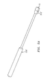
- FIG. 2A is a top view of one embodiment of the presently disclosed spacer trial
- FIG. 2B is a side view of the spacer trial shown in FIG. 2A;
- FIG. 3A is a side view of one embodiment of the presently disclosed spacer introducer with jaws in an open position
- FIG. 3B is a side view of the spacer introducer shown in FIG. 3A with the jaws in an approximated position;
- FIG. 4A is a top view of one embodiment of the presently disclosed bone tamp
- FIG. 4B is a side view of the bone tamp shown in FIG. 4A;
- FIG. 5 is a top view of the presently disclosed bone tamp positioned to engage the intervertebral spacer shown in FIG. 1;
- FIG. 5A is a perspective view of an alternate embodiment of the presently disclosed bone tamp
- FIG. 5B is a perspective cutaway view of the distal end of the bone tamp shown in FIG. 5A;
- FIG. 6 is a perspective view with parts separated of another preferred embodiment of the presently disclosed intervertebral spacer
- FIG. 7 is a perspective view with parts separated of another preferred embodiment of the presently disclosed intervertebral spacer
- FIG. 8A is a perspective view of yet another embodiment of the presently disclosed intervertebral spacer
- FIG. 8B is a perspective view of a femoral ring from which the intervertebral spacer shown in FIG. 8A can be formed.
- FIG. 8C is a perspective view of the cortical shell of the intervertebral spacer shown in FIG. 8 A.
- intervertebral spacer 10 includes a body 12 having a top 14 , a bottom 16 and at least one sidewall 18 .
- Body 12 is formed from dense cancellous human or animal bone which may be harvested from a bone such as a tibia, humerus, patella, calcaneus or femur.
- Body 12 may have a rectangular or square configuration and may be further configured to provide lordoses (not shown), i.e., top 14 and/or bottom 16 may be angled or shaped to maintain the natural curvature of the spine upon implantation. Alternately, body 12 may be formed to have other configurations including circular, hexagonal, etc.
- a trailing end 20 of spacer 10 includes a pair of angled walls 22 .
- cervical spacer 10 may be formed by making horizontal cuts 40 in the metaphysics (subchondral layer) of a proximal tibia 42 (FIG. 1A) to form rings 46 (FIG. 1 B).
- Each ring 46 includes an outer cortical shell 48 and an inner cancellous block plate 50 .
- Cortical shell 48 can be removed from about cancellous block 50 and block 50 can be cut and/or shaped to form cervical spacer 10 (FIG. 1 ).
- cervical spacer 10 By making horizontal cuts across the metaphysics of a long bone, cervical spacer 10 can be formed such that the loading on spacer 10 , after spacer 10 has been implanted between adjacent vertebrae, will be in the same direction as was the anatomical loading on the bone.
- FIGS. 2A and 2B illustrate the presently disclosed spacer trial shown generally as 100 .
- Spacer trial 100 includes a head portion 110 , a handle portion 112 and an elongated body portion 114 which interconnects head portion 110 and handle portion 112 .
- Handle portion 112 includes a recess 116 to facilitate gripping.
- the flat surface defining the base of recess 116 may also be used for etching indicia, e.g., instrument name and size, manufacturer, etc.
- spacer trial 100 is formed from a surgical grade metal such as stainless steel, e.g., 17-4 stainless steel.
- trial 100 can be formed from any material suitable for surgical use and meeting the requisite strength requirements including plastics, metals, aluminum, etc.
- Head portion 112 has a predetermined shape and size which, preferably, corresponds to the shape and size of a spacer to be introduced into a receiving bed formed in the intervertebral space.
- a set of spacer trials each having a progressively larger size head portion, are provided.
- a set of four trials may be provided each having a length of 11 mm and a width of 11 mm.
- the height of each trial increases by 1 mm from 5 mm to 8 mm.
- nine trials may be provided, each trial having a head portion having a length of 11 mm, a width of 14 mm and a height which increases by 1 mm from 5 mm to 13 mm.
- Other trial head portion dimensions and set sizes are also envisioned.
- a surgeon will grasp handle portion 112 of a spacer trial 100 from a set of spacer trials (not shown) and position head portion 110 of spacer trial 100 into a receiving bed formed between adjacent vertebrae. The surgeon will repeat this process until the head portion of a spacer trial fits snugly within the receiving bed. Since each spacer trial includes a head portion which corresponds in size to a particular size spacer, the appropriate size spacer is identified when a spacer trial fits snugly within the receiving bed.
- FIGS. 3A and 3B illustrate the presently disclosed spacer introducer shown generally as 200 .
- Spacer introducer 200 includes a handle 210 , a stationary arm 212 , and a pivotable arm 214 .
- Each arm has a proximal end and a distal end having a jaw 216 and 217 , respectively, formed thereon.
- the proximal end of stationary arm 212 is fastened to handle 210 using any known fastening technique including welding, screw threads, adhesives, etc . . .
- Each arm 212 and 214 includes a centrally located transverse extension 218 and 219 , respectively, adapted to receive a pivot member 220 .
- Pivotable arm 214 is pivotably secured to stationary arm 212 about pivot member 220 such that jaws 216 and 217 can be moved between spaced (FIG. 3A) and approximated positions (FIG. 3 B).
- a biasing member (not shown) is positioned between transverse extensions 218 and 219 to urge jaws 216 and 217 to the approximated position.
- introducer 200 is formed from surgical grade steel, although other materials suitable for surgical use may also be used including plastics, metals, etc.
- a surgeon can grasp introducer 200 by handle 210 , which may include a knurled or roughened outer surface 230 to improve gripping. Using his thumb, the surgeon can press on the proximal end of pivotable arm 214 to pivot jaw 217 away from jaw 216 to the spaced position. A spacer or implant can now be positioned between jaws 216 and 217 . The surgeon can now release pivotable arm 214 to allow jaw 217 to be urged towards the approximated position by the biasing member to compress the trailing end of a spacer between the jaws. Each jaw 216 and 217 may include ridges 224 to prevent the spacer from slipping from between the jaws. The surgeon can now maneuver the introducer 200 to position the leading end of a spacer into a receiving bed formed between the adjacent vertebrae.
- FIGS. 4A and 4B illustrate the presently disclosed bone tamp shown generally as 300 .
- Bone tamp 300 includes a handle portion 310 , a head portion 312 and an elongated body portion 314 interconnecting head portion 312 and handle portion 310 .
- Head portion 312 includes a pair of spaced angled extensions 316 defining a recess 318 .
- Recess 318 is configured to matingly engage trailing end 20 of spacer 10 .
- a pair of depth limiting stops 322 extend upwardly and downwardly from head portion 312 . Stops 322 are positioned to engage the adjacent vertebrae after a spacer has been driven into a receiving bed formed in the intervertebral space.
- head portion 312 ′ of bone tamp 300 ′ does not include stops.
- FIG. 6 illustrates an alternate embodiment of the presently disclosed intervertebral spacer which is shown generally as 400 .
- Spacer 400 is similar to spacer 10 , but also includes a plug or pillar 412 formed of cortical bone tissue. Pillar 412 is positioned within a bore 414 extending between top and bottom surfaces 416 and 418 of body 410 .
- pillar 112 may assume other configurations, e.g., rectangular, hexagonal, square, etc.
- intervertebral spacer may be formed having plurality of spaced pillars.
- intervertebral spacer 500 shown in FIG.
- the spacer 7 includes four cortical pillars supported within bores 514 extending between top and bottom surfaces 516 and 518 of cancellous body 510 .
- the spacer has improved strength while maintaining its osteoinductive properties.
- FIG. 8A illustrates another embodiment of the presently disclosed intervertebral spacer shown generally as 600 .
- Spacer 600 has a substantially rectangular shape and includes a U-shaped body portion 610 and a central body portion 612 .
- U-shaped body portion 610 is formed of cortical bone and includes a base 614 and first and second legs 616 and 618 .
- Central body 612 is formed of cancellous bone which is positioned between first and second legs 616 and 618 of U-shaped body portion 610 .
- a retaining pin 620 may be positioned to extend between legs 616 and 618 through body portion 612 to prevent body portion 612 from separating from body portion 610 .
- Retaining pin 620 may be formed of cancellous or cortical bone, or alternately, from any bio-compatible material having the requisite strength requirements including metals, plastics, composites, etc . . .
- cervical spacer 600 can be formed by cutting U-shaped portion 610 from a cortical ring 650 which may be cut from a long bone, e.g., femur, tibia, fibula, ulna or radius.
- Body portion 610 (FIG. 8A) which is formed from dense cancellous bone, can be inserted thereafter and pinned therein if necessary.
- Each of intervertebral spacers 10 , 400 , 500 and 600 may be formed from partially or fully demineralized bone.
- the bone may be partially demineralized, e.g., surface demineralized, to provide a degree of flexibility to the spacer or to improve the osteoinductive characteristics of the spacer.
- the spacer may be formed of fully demineralized bone for the same reasons.
- the cancellous body of the spacer is formed of partially or fully demineralized bone while the cortical pillars are formed of mineralized bone. By demineralizing the cancellous body an osteoconductive matrix is provided about the cortical pillars to maintain the pillars in their designated spatial relationship.
- any portion of implants 10 , 400 , 500 and 600 may be partial or fully demineralized to provide the improved characteristics discussed above.
- the number of cortical pillars may be varied to suit a particular surgical procedure.
- the cortical bone may be replaced with other bio-compatible materials having the requisite strength requirements including ceramics, polymers, composites, etc.
- BMP's may be added to the material used to construct the intervertebral spacer to promote osteoinductivity.
- the spacers are not limited to use in the cervical spine, but rather may be suitable for use in the lumbar and/or thoracic spine.
- the intervertebral spacer is not limited to the shape illustrated but rather may be configured to suit a particular procedure, i.e., the spacer may be circular, rectangular, square, etc.
Abstract
Description
Claims (11)
Priority Applications (8)
| Application Number | Priority Date | Filing Date | Title |
|---|---|---|---|
| US09/734,860 US6638310B2 (en) | 2000-07-26 | 2000-12-12 | Intervertebral spacer and implant insertion instrumentation |
| KR10-2003-7001091A KR20030036636A (en) | 2000-07-26 | 2001-07-26 | Intervertebral spacer and implant insertion instrumentation |
| AU2001277187A AU2001277187A1 (en) | 2000-07-26 | 2001-07-26 | Intervertebral spacer and implant insertion instrumentation |
| NZ52440301A NZ524403A (en) | 2000-07-26 | 2001-07-26 | Intervertebral spacer and implant insertion instrumentation |
| PCT/US2001/023481 WO2002007654A2 (en) | 2000-07-26 | 2001-07-26 | Intervertebral spacer and implant insertion instrumentation |
| CA002417181A CA2417181A1 (en) | 2000-07-26 | 2001-07-26 | Intervertebral spacer and implant insertion instrumentation |
| EP01954976A EP1303235A2 (en) | 2000-07-26 | 2001-07-26 | Intervertebral spacer and implant insertion instrumentation |
| JP2002513392A JP2004504102A (en) | 2000-07-26 | 2001-07-26 | Intravertebral spacer and implant insertion device |
Applications Claiming Priority (2)
| Application Number | Priority Date | Filing Date | Title |
|---|---|---|---|
| US22094100P | 2000-07-26 | 2000-07-26 | |
| US09/734,860 US6638310B2 (en) | 2000-07-26 | 2000-12-12 | Intervertebral spacer and implant insertion instrumentation |
Publications (2)
| Publication Number | Publication Date |
|---|---|
| US20020016633A1 US20020016633A1 (en) | 2002-02-07 |
| US6638310B2 true US6638310B2 (en) | 2003-10-28 |
Family
ID=26915341
Family Applications (1)
| Application Number | Title | Priority Date | Filing Date |
|---|---|---|---|
| US09/734,860 Expired - Lifetime US6638310B2 (en) | 2000-07-26 | 2000-12-12 | Intervertebral spacer and implant insertion instrumentation |
Country Status (8)
| Country | Link |
|---|---|
| US (1) | US6638310B2 (en) |
| EP (1) | EP1303235A2 (en) |
| JP (1) | JP2004504102A (en) |
| KR (1) | KR20030036636A (en) |
| AU (1) | AU2001277187A1 (en) |
| CA (1) | CA2417181A1 (en) |
| NZ (1) | NZ524403A (en) |
| WO (1) | WO2002007654A2 (en) |
Cited By (76)
| Publication number | Priority date | Publication date | Assignee | Title |
|---|---|---|---|---|
| US20010041941A1 (en) * | 2000-03-22 | 2001-11-15 | Boyer Michael L. | Multipiece implants formed of bone material |
| US20030135275A1 (en) * | 2001-11-09 | 2003-07-17 | Javier Garcia | Instruments and methods for inserting a spinal implant |
| US20030167092A1 (en) * | 2001-02-06 | 2003-09-04 | Foley Kevin T. | Spinal bone implant |
| US20030229397A1 (en) * | 2001-12-28 | 2003-12-11 | Davis Reginald J. | Pseudo arthrosis device |
| US20050010234A1 (en) * | 2001-07-16 | 2005-01-13 | Ralph James D. | Method of distracting vertebral bones |
| US20050107879A1 (en) * | 2002-02-13 | 2005-05-19 | John Christensen | Implant for spine and method for manufacturing same |
| US20050251257A1 (en) * | 2004-05-04 | 2005-11-10 | Mitchell Margaret E | Spinal implants with body and insert |
| US20060200166A1 (en) * | 2000-07-06 | 2006-09-07 | Zimmer Spine, Inc. | Bone implants and methods |
| US20070162128A1 (en) * | 2005-12-16 | 2007-07-12 | Sdgi Holdings, Inc. | Intervertebral spacer and insertion tool |
| US20070208424A1 (en) * | 2003-09-02 | 2007-09-06 | Dominique Messerli | Multipiece allograft implant |
| US20070213827A1 (en) * | 2005-09-28 | 2007-09-13 | Arramon Yves P | Hardened calcium phosphate cement bone implants |
| US20080188940A1 (en) * | 2007-02-01 | 2008-08-07 | Zimmer Spine, Inc. | Spinal Implant |
| US20080200985A1 (en) * | 2007-02-19 | 2008-08-21 | Zimmer Spine, Inc. | Spinal implant |
| US20080208342A1 (en) * | 2007-02-27 | 2008-08-28 | Zimmer Spine, Inc. | Spinal implant |
| US20090099661A1 (en) * | 2007-08-14 | 2009-04-16 | Jinia Bhattacharya | Multiple component osteoimplant |
| US20090105825A1 (en) * | 2007-10-19 | 2009-04-23 | Greg Foreman | Fusion methods using autologous stem cells |
| US20090105824A1 (en) * | 2007-10-19 | 2009-04-23 | Jones Robert J | Spinal fusion device and associated methods |
| US20090132046A1 (en) * | 2005-05-20 | 2009-05-21 | D.L.P. | Implant for Use with an Osteotomy Plate |
| US7662185B2 (en) | 1999-12-30 | 2010-02-16 | Osteotech, Inc. | Intervertebral implants |
| US20100042216A1 (en) * | 2008-08-15 | 2010-02-18 | Pioneer Surgical Technology, Inc. | Implant for Deploying Bone Graft Material and Methods Thereof |
| US7726002B2 (en) | 2001-12-05 | 2010-06-01 | Osteotech, Inc. | Processes for making spinal intervertebral implant, interconnections for such implant |
| US20100185288A1 (en) * | 2009-01-21 | 2010-07-22 | Warsaw Orthopedic, Inc | Spinal nucleus replacement implant |
| US7780708B2 (en) | 2000-10-20 | 2010-08-24 | Osteotech, Inc. | Implant retaining device |
| US20100228350A1 (en) * | 2009-03-04 | 2010-09-09 | Warsaw Orthopedic, Inc. | Spinal nucleus replacement implants |
| US7799081B2 (en) | 2004-09-14 | 2010-09-21 | Aeolin, Llc | System and method for spinal fusion |
| US7846207B2 (en) | 2003-02-06 | 2010-12-07 | Synthes Usa, Llc | Intervertebral implant |
| US7905922B2 (en) | 2006-12-20 | 2011-03-15 | Zimmer Spine, Inc. | Surgical implant suitable for replacement of an intervertebral disc |
| US20110144766A1 (en) * | 2008-06-19 | 2011-06-16 | Shreedhar Kale | Allograft Bone Plugs, Systems and Techniques |
| US20110288652A1 (en) * | 2010-05-20 | 2011-11-24 | Indiana University Research & Technology Corporation | Materials and methods for treating critically sized defects in mouse bone |
| US8333985B2 (en) | 2004-01-27 | 2012-12-18 | Warsaw Orthopedic, Inc. | Non-glycerol stabilized bone graft |
| US8361153B2 (en) | 2001-07-16 | 2013-01-29 | Spinecore, Inc. | Porous intervertebral distraction spacers |
| US8372157B2 (en) | 2007-02-12 | 2013-02-12 | Warsaw Orthopedic, Inc. | Joint revision implant |
| US8425603B2 (en) | 2008-12-22 | 2013-04-23 | Synthes Usa, Llc | Orthopedic implant with flexible keel |
| US8540774B2 (en) | 2007-11-16 | 2013-09-24 | DePuy Synthes Products, LLC | Low profile intervertebral implant |
| US20130282018A1 (en) * | 2006-09-19 | 2013-10-24 | Warsaw Orthopedic Inc. | Instruments and methods for spinal implant revision |
| US8961606B2 (en) | 2011-09-16 | 2015-02-24 | Globus Medical, Inc. | Multi-piece intervertebral implants |
| US9011538B2 (en) | 2009-01-21 | 2015-04-21 | Warsaw Orthopedic, Inc. | Methods of spinal nucleus replacemennt |
| US9039775B2 (en) | 2003-03-31 | 2015-05-26 | DePuy Synthes Products, Inc. | Spinal fixation plates |
| US9149365B2 (en) | 2013-03-05 | 2015-10-06 | Globus Medical, Inc. | Low profile plate |
| US9192419B2 (en) | 2008-11-07 | 2015-11-24 | DePuy Synthes Products, Inc. | Zero-profile interbody spacer and coupled plate assembly |
| US9204975B2 (en) | 2011-09-16 | 2015-12-08 | Globus Medical, Inc. | Multi-piece intervertebral implants |
| US9220604B2 (en) | 2010-12-21 | 2015-12-29 | DePuy Synthes Products, Inc. | Intervertebral implants, systems, and methods of use |
| US9237957B2 (en) | 2011-09-16 | 2016-01-19 | Globus Medical, Inc. | Low profile plate |
| US9241809B2 (en) | 2010-12-21 | 2016-01-26 | DePuy Synthes Products, Inc. | Intervertebral implants, systems, and methods of use |
| US20160113774A1 (en) * | 2014-10-22 | 2016-04-28 | DePuy Synthes Products, LLC | Intervertebral implants, systems, and methods of use |
| US9398960B2 (en) | 2011-09-16 | 2016-07-26 | Globus Medical, Inc. | Multi-piece intervertebral implants |
| US9539109B2 (en) | 2011-09-16 | 2017-01-10 | Globus Medical, Inc. | Low profile plate |
| US9566169B2 (en) | 2014-03-13 | 2017-02-14 | DePuy Synthes Products, Inc. | ACIS allograft designs |
| US9572681B2 (en) | 2002-02-19 | 2017-02-21 | DePuy Synthes Products, Inc. | Intervertebral implant |
| US9579214B1 (en) * | 2011-03-01 | 2017-02-28 | John W. McClellan | Peripheral vertebral body spacer implant and insertion tool |
| US9585764B2 (en) * | 2012-07-26 | 2017-03-07 | Warsaw Orthopedic, Inc. | Bone implant device |
| US9681959B2 (en) | 2011-09-16 | 2017-06-20 | Globus Medical, Inc. | Low profile plate |
| US9770340B2 (en) | 2011-09-16 | 2017-09-26 | Globus Medical, Inc. | Multi-piece intervertebral implants |
| US20170281363A1 (en) * | 2008-08-13 | 2017-10-05 | Smed-Ta/Td, Llc | Orthopaedic implant with porous structural member |
| US9848994B2 (en) | 2011-09-16 | 2017-12-26 | Globus Medical, Inc. | Low profile plate |
| US9867714B1 (en) | 2011-09-23 | 2018-01-16 | Samy Abdou | Spinal fixation devices and methods of use |
| WO2018022347A1 (en) * | 2016-07-26 | 2018-02-01 | Ctl Medical Corporation | Acif cage, cage system and method |
| US10111757B2 (en) | 2012-10-22 | 2018-10-30 | Cogent Spine, LLC | Devices and methods for spinal stabilization and instrumentation |
| US10245155B2 (en) | 2011-09-16 | 2019-04-02 | Globus Medical, Inc. | Low profile plate |
| US10271960B2 (en) | 2017-04-05 | 2019-04-30 | Globus Medical, Inc. | Decoupled spacer and plate and method of installing the same |
| US10376385B2 (en) | 2017-04-05 | 2019-08-13 | Globus Medical, Inc. | Decoupled spacer and plate and method of installing the same |
| US10512548B2 (en) | 2006-02-27 | 2019-12-24 | DePuy Synthes Products, Inc. | Intervertebral implant with fixation geometry |
| US10543107B2 (en) | 2009-12-07 | 2020-01-28 | Samy Abdou | Devices and methods for minimally invasive spinal stabilization and instrumentation |
| US10548740B1 (en) | 2016-10-25 | 2020-02-04 | Samy Abdou | Devices and methods for vertebral bone realignment |
| US10695105B2 (en) | 2012-08-28 | 2020-06-30 | Samy Abdou | Spinal fixation devices and methods of use |
| US10842645B2 (en) | 2008-08-13 | 2020-11-24 | Smed-Ta/Td, Llc | Orthopaedic implant with porous structural member |
| US10857003B1 (en) | 2015-10-14 | 2020-12-08 | Samy Abdou | Devices and methods for vertebral stabilization |
| US10918498B2 (en) | 2004-11-24 | 2021-02-16 | Samy Abdou | Devices and methods for inter-vertebral orthopedic device placement |
| US10973648B1 (en) | 2016-10-25 | 2021-04-13 | Samy Abdou | Devices and methods for vertebral bone realignment |
| US11006982B2 (en) | 2012-02-22 | 2021-05-18 | Samy Abdou | Spinous process fixation devices and methods of use |
| US11051953B2 (en) | 2019-07-31 | 2021-07-06 | Zavation Medical Products, Llc | Porous spinal implant |
| US11179248B2 (en) | 2018-10-02 | 2021-11-23 | Samy Abdou | Devices and methods for spinal implantation |
| US11278420B2 (en) | 2019-10-25 | 2022-03-22 | Zavation, Llc | Recessed pocket spinal implant |
| US11399955B2 (en) | 2002-10-21 | 2022-08-02 | Warsaw Orthopedic, Inc. | Systems and techniques for restoring and maintaining intervertebral anatomy |
| US11717417B2 (en) | 2011-09-16 | 2023-08-08 | Globus Medical Inc. | Low profile plate |
| US11857436B1 (en) | 2019-07-31 | 2024-01-02 | Zavation Medical Products, Llc | Porous spinal implant |
Families Citing this family (54)
| Publication number | Priority date | Publication date | Assignee | Title |
|---|---|---|---|---|
| FR2767675B1 (en) * | 1997-08-26 | 1999-12-03 | Materiel Orthopedique En Abreg | INTERSOMATIC IMPLANT AND ANCILLARY OF PREPARATION SUITABLE FOR ALLOWING ITS POSITION |
| US6045551A (en) | 1998-02-06 | 2000-04-04 | Bonutti; Peter M. | Bone suture |
| US6200347B1 (en) * | 1999-01-05 | 2001-03-13 | Lifenet | Composite bone graft, method of making and using same |
| WO2001087369A2 (en) * | 2000-05-12 | 2001-11-22 | Osteotech, Inc. | Osteoimplant and method for making same |
| ATE388677T1 (en) | 1999-07-02 | 2008-03-15 | Spine Solutions Inc | INTERVERBARY IMPLANT |
| US6447516B1 (en) * | 1999-08-09 | 2002-09-10 | Peter M. Bonutti | Method of securing tissue |
| US6368343B1 (en) * | 2000-03-13 | 2002-04-09 | Peter M. Bonutti | Method of using ultrasonic vibration to secure body tissue |
| DE59914213D1 (en) | 1999-09-14 | 2007-04-05 | Spine Solutions Inc | INSERT INSTRUMENT FOR A INTERMEDIATE IMPLANT |
| US6635073B2 (en) | 2000-05-03 | 2003-10-21 | Peter M. Bonutti | Method of securing body tissue |
| US7094251B2 (en) | 2002-08-27 | 2006-08-22 | Marctec, Llc. | Apparatus and method for securing a suture |
| US9138222B2 (en) | 2000-03-13 | 2015-09-22 | P Tech, Llc | Method and device for securing body tissue |
| US7169183B2 (en) * | 2000-03-14 | 2007-01-30 | Warsaw Orthopedic, Inc. | Vertebral implant for promoting arthrodesis of the spine |
| US6719765B2 (en) | 2001-12-03 | 2004-04-13 | Bonutti 2003 Trust-A | Magnetic suturing system and method |
| AU2002366381A1 (en) * | 2001-12-18 | 2003-06-30 | Ebi, L.P. | Spinal implants |
| US20040106927A1 (en) * | 2002-03-01 | 2004-06-03 | Ruffner Brian M. | Vertebral distractor |
| US9155544B2 (en) | 2002-03-20 | 2015-10-13 | P Tech, Llc | Robotic systems and methods |
| US8038713B2 (en) | 2002-04-23 | 2011-10-18 | Spinecore, Inc. | Two-component artificial disc replacements |
| US6706068B2 (en) | 2002-04-23 | 2004-03-16 | Bret A. Ferree | Artificial disc replacements with natural kinematics |
| GB0221527D0 (en) * | 2002-09-17 | 2002-10-23 | Depuy Int Ltd | Spinal implantation device |
| US7323011B2 (en) | 2002-10-18 | 2008-01-29 | Musculoskeletal Transplant Foundation | Cortical and cancellous allograft cervical fusion block |
| US7125425B2 (en) * | 2002-10-21 | 2006-10-24 | Sdgi Holdings, Inc. | Systems and techniques for restoring and maintaining intervertebral anatomy |
| US6761739B2 (en) | 2002-11-25 | 2004-07-13 | Musculoskeletal Transplant Foundation | Cortical and cancellous allograft spacer |
| US7204852B2 (en) | 2002-12-13 | 2007-04-17 | Spine Solutions, Inc. | Intervertebral implant, insertion tool and method of inserting same |
| US6908484B2 (en) | 2003-03-06 | 2005-06-21 | Spinecore, Inc. | Cervical disc replacement |
| US7491204B2 (en) | 2003-04-28 | 2009-02-17 | Spine Solutions, Inc. | Instruments and method for preparing an intervertebral space for receiving an artificial disc implant |
| US7497864B2 (en) | 2003-04-30 | 2009-03-03 | Marctec, Llc. | Tissue fastener and methods for using same |
| US7803162B2 (en) * | 2003-07-21 | 2010-09-28 | Spine Solutions, Inc. | Instruments and method for inserting an intervertebral implant |
| US20050038511A1 (en) * | 2003-08-15 | 2005-02-17 | Martz Erik O. | Transforaminal lumbar interbody fusion (TLIF) implant, surgical procedure and instruments for insertion of spinal implant in a spinal disc space |
| US20050049703A1 (en) * | 2003-08-26 | 2005-03-03 | Lee Casey K. | Spinal implant |
| US20050065613A1 (en) * | 2003-09-24 | 2005-03-24 | Gross Jeffrey M. | Reinforced fusion implant |
| JP2007519429A (en) * | 2003-10-17 | 2007-07-19 | スパインコア,インコーポレイテッド | Intervertebral disc replacement trial |
| US8123757B2 (en) * | 2003-12-31 | 2012-02-28 | Depuy Spine, Inc. | Inserter instrument and implant clip |
| US20080039873A1 (en) | 2004-03-09 | 2008-02-14 | Marctec, Llc. | Method and device for securing body tissue |
| WO2006044920A2 (en) * | 2004-10-19 | 2006-04-27 | Osteotech, Inc. | Adjustable instrumentation for spinal implant insertion |
| US9271766B2 (en) | 2004-10-26 | 2016-03-01 | P Tech, Llc | Devices and methods for stabilizing tissue and implants |
| US9463012B2 (en) | 2004-10-26 | 2016-10-11 | P Tech, Llc | Apparatus for guiding and positioning an implant |
| US20060089646A1 (en) | 2004-10-26 | 2006-04-27 | Bonutti Peter M | Devices and methods for stabilizing tissue and implants |
| US9173647B2 (en) | 2004-10-26 | 2015-11-03 | P Tech, Llc | Tissue fixation system |
| US9089323B2 (en) | 2005-02-22 | 2015-07-28 | P Tech, Llc | Device and method for securing body tissue |
| US7967820B2 (en) | 2006-02-07 | 2011-06-28 | P Tech, Llc. | Methods and devices for trauma welding |
| US8496657B2 (en) | 2006-02-07 | 2013-07-30 | P Tech, Llc. | Methods for utilizing vibratory energy to weld, stake and/or remove implants |
| US11278331B2 (en) | 2006-02-07 | 2022-03-22 | P Tech Llc | Method and devices for intracorporeal bonding of implants with thermal energy |
| US11253296B2 (en) | 2006-02-07 | 2022-02-22 | P Tech, Llc | Methods and devices for intracorporeal bonding of implants with thermal energy |
| US11246638B2 (en) | 2006-05-03 | 2022-02-15 | P Tech, Llc | Methods and devices for utilizing bondable materials |
| AU2007276755A1 (en) | 2006-07-24 | 2008-01-31 | Spine Solutions, Inc. | Intervertebral implant with keel |
| CA2659024A1 (en) | 2006-07-31 | 2008-02-07 | Synthes (Usa) | Drilling/milling guide and keel cut preparation system |
| US9066994B2 (en) * | 2006-08-31 | 2015-06-30 | Warsaw Orthopedic, Inc. | Demineralized cancellous strip DBM graft |
| US8617185B2 (en) | 2007-02-13 | 2013-12-31 | P Tech, Llc. | Fixation device |
| EP2400899A4 (en) | 2009-02-24 | 2015-03-18 | P Tech Llc | Methods and devices for utilizing bondable materials |
| WO2012099852A1 (en) * | 2011-01-17 | 2012-07-26 | Cibor, Inc. | Reinforced carbon fiber/carbon foam intervertebral spine fusion device |
| US10076377B2 (en) | 2013-01-05 | 2018-09-18 | P Tech, Llc | Fixation systems and methods |
| US9345589B2 (en) * | 2013-12-19 | 2016-05-24 | Ilion Medical, Inc. | Bone implants for orthopedic procedures and corresponding methods |
| US10058393B2 (en) | 2015-10-21 | 2018-08-28 | P Tech, Llc | Systems and methods for navigation and visualization |
| CN112469351A (en) * | 2018-06-25 | 2021-03-09 | 康曼德公司 | Ligament revision system |
Citations (43)
| Publication number | Priority date | Publication date | Assignee | Title |
|---|---|---|---|---|
| US4484570A (en) | 1980-05-28 | 1984-11-27 | Synthes Ltd. | Device comprising an implant and screws for fastening said implant to a bone, and a device for connecting two separated pieces of bone |
| US4516276A (en) | 1979-12-18 | 1985-05-14 | Oscobal Ag | Bone substitute and a method of production thereof |
| US4566466A (en) | 1984-04-16 | 1986-01-28 | Ripple Dale B | Surgical instrument |
| US4637931A (en) | 1984-10-09 | 1987-01-20 | The United States Of America As Represented By The Secretary Of The Army | Polyactic-polyglycolic acid copolymer combined with decalcified freeze-dried bone for use as a bone repair material |
| US4834757A (en) | 1987-01-22 | 1989-05-30 | Brantigan John W | Prosthetic implant |
| US4950296A (en) * | 1988-04-07 | 1990-08-21 | Mcintyre Jonathan L | Bone grafting units |
| US4961740A (en) | 1988-10-17 | 1990-10-09 | Surgical Dynamics, Inc. | V-thread fusion cage and method of fusing a bone joint |
| US5061786A (en) | 1989-05-25 | 1991-10-29 | Genentech, Inc. | Biologically active polypeptides based on transforming growth factor-β |
| US5192327A (en) | 1991-03-22 | 1993-03-09 | Brantigan John W | Surgical prosthetic implant for vertebrae |
| US5207710A (en) | 1988-09-29 | 1993-05-04 | Collagen Corporation | Method for improving implant fixation |
| US5298254A (en) | 1989-09-21 | 1994-03-29 | Osteotech, Inc. | Shaped, swollen demineralized bone and its use in bone repair |
| US5314476A (en) | 1992-02-04 | 1994-05-24 | Osteotech, Inc. | Demineralized bone particles and flowable osteogenic composition containing same |
| US5423817A (en) | 1993-07-29 | 1995-06-13 | Lin; Chih-I | Intervertebral fusing device |
| US5443514A (en) | 1993-10-01 | 1995-08-22 | Acromed Corporation | Method for using spinal implants |
| US5507813A (en) | 1993-12-09 | 1996-04-16 | Osteotech, Inc. | Shaped materials derived from elongate bone particles |
| US5522899A (en) | 1988-06-28 | 1996-06-04 | Sofamor Danek Properties, Inc. | Artificial spinal fusion implants |
| US5545222A (en) | 1991-08-12 | 1996-08-13 | Bonutti; Peter M. | Method using human tissue |
| US5607424A (en) | 1995-04-10 | 1997-03-04 | Tropiano; Patrick | Domed cage |
| US5609636A (en) | 1994-05-23 | 1997-03-11 | Spine-Tech, Inc. | Spinal implant |
| US5653763A (en) | 1996-03-29 | 1997-08-05 | Fastenetix, L.L.C. | Intervertebral space shape conforming cage device |
| US5709683A (en) | 1995-12-19 | 1998-01-20 | Spine-Tech, Inc. | Interbody bone implant having conjoining stabilization features for bony fusion |
| US5716415A (en) | 1993-10-01 | 1998-02-10 | Acromed Corporation | Spinal implant |
| US5728159A (en) * | 1997-01-02 | 1998-03-17 | Musculoskeletal Transplant Foundation | Serrated bone graft |
| US5749916A (en) | 1997-01-21 | 1998-05-12 | Spinal Innovations | Fusion implant |
| US5769897A (en) | 1991-12-13 | 1998-06-23 | Haerle; Anton | Synthetic bone |
| US5782830A (en) | 1995-10-16 | 1998-07-21 | Sdgi Holdings, Inc. | Implant insertion device |
| US5800547A (en) | 1994-08-20 | 1998-09-01 | Schafer Micomed Gmbh | Ventral intervertebral implant |
| US5814084A (en) | 1996-01-16 | 1998-09-29 | University Of Florida Tissue Bank, Inc. | Diaphysial cortical dowel |
| US5824078A (en) | 1996-03-11 | 1998-10-20 | The Board Of Trustees Of The University Of Arkansas | Composite allograft, press, and methods |
| US5868749A (en) | 1996-04-05 | 1999-02-09 | Reed; Thomas M. | Fixation devices |
| US5888222A (en) | 1995-10-16 | 1999-03-30 | Sdgi Holding, Inc. | Intervertebral spacers |
| US5899939A (en) | 1998-01-21 | 1999-05-04 | Osteotech, Inc. | Bone-derived implant for load-supporting applications |
| US5984967A (en) | 1995-03-27 | 1999-11-16 | Sdgi Holdings, Inc. | Osteogenic fusion devices |
| US5989289A (en) | 1995-10-16 | 1999-11-23 | Sdgi Holdings, Inc. | Bone grafts |
| US6030635A (en) | 1998-02-27 | 2000-02-29 | Musculoskeletal Transplant Foundation | Malleable paste for filling bone defects |
| WO2000024327A2 (en) | 1998-10-28 | 2000-05-04 | Sdgi Holdings, Inc. | Interbody fusion grafts and instrumentation |
| US6083225A (en) | 1996-03-14 | 2000-07-04 | Surgical Dynamics, Inc. | Method and instrumentation for implant insertion |
| WO2000040177A1 (en) | 1999-01-05 | 2000-07-13 | Lifenet | Composite bone graft, method of making and using same |
| WO2000040179A1 (en) | 1999-01-08 | 2000-07-13 | Sdgi Holdings, Inc. | Flexible implant using partially demineralized bone |
| US6111164A (en) | 1996-06-21 | 2000-08-29 | Musculoskeletal Transplant Foundation | Bone graft insert |
| US6113638A (en) | 1999-02-26 | 2000-09-05 | Williams; Lytton A. | Method and apparatus for intervertebral implant anchorage |
| US6159215A (en) | 1997-12-19 | 2000-12-12 | Depuy Acromed, Inc. | Insertion instruments and method for delivering a vertebral body spacer |
| US6379385B1 (en) * | 2000-01-06 | 2002-04-30 | Tutogen Medical Gmbh | Implant of bone matter |
-
2000
- 2000-12-12 US US09/734,860 patent/US6638310B2/en not_active Expired - Lifetime
-
2001
- 2001-07-26 KR KR10-2003-7001091A patent/KR20030036636A/en not_active Application Discontinuation
- 2001-07-26 EP EP01954976A patent/EP1303235A2/en not_active Withdrawn
- 2001-07-26 NZ NZ52440301A patent/NZ524403A/en unknown
- 2001-07-26 AU AU2001277187A patent/AU2001277187A1/en not_active Abandoned
- 2001-07-26 JP JP2002513392A patent/JP2004504102A/en active Pending
- 2001-07-26 WO PCT/US2001/023481 patent/WO2002007654A2/en not_active Application Discontinuation
- 2001-07-26 CA CA002417181A patent/CA2417181A1/en not_active Abandoned
Patent Citations (51)
| Publication number | Priority date | Publication date | Assignee | Title |
|---|---|---|---|---|
| US4516276A (en) | 1979-12-18 | 1985-05-14 | Oscobal Ag | Bone substitute and a method of production thereof |
| US4484570A (en) | 1980-05-28 | 1984-11-27 | Synthes Ltd. | Device comprising an implant and screws for fastening said implant to a bone, and a device for connecting two separated pieces of bone |
| US4566466A (en) | 1984-04-16 | 1986-01-28 | Ripple Dale B | Surgical instrument |
| US4637931A (en) | 1984-10-09 | 1987-01-20 | The United States Of America As Represented By The Secretary Of The Army | Polyactic-polyglycolic acid copolymer combined with decalcified freeze-dried bone for use as a bone repair material |
| US4834757A (en) | 1987-01-22 | 1989-05-30 | Brantigan John W | Prosthetic implant |
| US4950296A (en) * | 1988-04-07 | 1990-08-21 | Mcintyre Jonathan L | Bone grafting units |
| US5776199A (en) | 1988-06-28 | 1998-07-07 | Sofamor Danek Properties | Artificial spinal fusion implants |
| US5522899A (en) | 1988-06-28 | 1996-06-04 | Sofamor Danek Properties, Inc. | Artificial spinal fusion implants |
| US5207710A (en) | 1988-09-29 | 1993-05-04 | Collagen Corporation | Method for improving implant fixation |
| US4961740A (en) | 1988-10-17 | 1990-10-09 | Surgical Dynamics, Inc. | V-thread fusion cage and method of fusing a bone joint |
| US4961740B1 (en) | 1988-10-17 | 1997-01-14 | Surgical Dynamics Inc | V-thread fusion cage and method of fusing a bone joint |
| US5061786A (en) | 1989-05-25 | 1991-10-29 | Genentech, Inc. | Biologically active polypeptides based on transforming growth factor-β |
| US5298254A (en) | 1989-09-21 | 1994-03-29 | Osteotech, Inc. | Shaped, swollen demineralized bone and its use in bone repair |
| US5439684A (en) | 1989-09-21 | 1995-08-08 | Osteotech, Inc. | Shaped, swollen demineralized bone and its use in bone repair |
| US5192327A (en) | 1991-03-22 | 1993-03-09 | Brantigan John W | Surgical prosthetic implant for vertebrae |
| US6132472A (en) | 1991-08-12 | 2000-10-17 | Bonutti; Peter M. | Tissue press and system |
| US5888219A (en) | 1991-08-12 | 1999-03-30 | Bonutti; Peter M. | Method of using human tissue with a tissue press and system |
| US5545222A (en) | 1991-08-12 | 1996-08-13 | Bonutti; Peter M. | Method using human tissue |
| US5662710A (en) | 1991-08-12 | 1997-09-02 | Bonutti; Peter M. | Tissue press method of use |
| US5769897A (en) | 1991-12-13 | 1998-06-23 | Haerle; Anton | Synthetic bone |
| US5314476A (en) | 1992-02-04 | 1994-05-24 | Osteotech, Inc. | Demineralized bone particles and flowable osteogenic composition containing same |
| US5423817A (en) | 1993-07-29 | 1995-06-13 | Lin; Chih-I | Intervertebral fusing device |
| US5716415A (en) | 1993-10-01 | 1998-02-10 | Acromed Corporation | Spinal implant |
| US5443514A (en) | 1993-10-01 | 1995-08-22 | Acromed Corporation | Method for using spinal implants |
| US5507813A (en) | 1993-12-09 | 1996-04-16 | Osteotech, Inc. | Shaped materials derived from elongate bone particles |
| US5609636A (en) | 1994-05-23 | 1997-03-11 | Spine-Tech, Inc. | Spinal implant |
| US5800547A (en) | 1994-08-20 | 1998-09-01 | Schafer Micomed Gmbh | Ventral intervertebral implant |
| US5984967A (en) | 1995-03-27 | 1999-11-16 | Sdgi Holdings, Inc. | Osteogenic fusion devices |
| US5607424A (en) | 1995-04-10 | 1997-03-04 | Tropiano; Patrick | Domed cage |
| US6066174A (en) | 1995-10-16 | 2000-05-23 | Sdgi Holdings, Inc. | Implant insertion device |
| US5989289A (en) | 1995-10-16 | 1999-11-23 | Sdgi Holdings, Inc. | Bone grafts |
| US5888222A (en) | 1995-10-16 | 1999-03-30 | Sdgi Holding, Inc. | Intervertebral spacers |
| US5782830A (en) | 1995-10-16 | 1998-07-21 | Sdgi Holdings, Inc. | Implant insertion device |
| US5709683A (en) | 1995-12-19 | 1998-01-20 | Spine-Tech, Inc. | Interbody bone implant having conjoining stabilization features for bony fusion |
| US5814084A (en) | 1996-01-16 | 1998-09-29 | University Of Florida Tissue Bank, Inc. | Diaphysial cortical dowel |
| US5824078A (en) | 1996-03-11 | 1998-10-20 | The Board Of Trustees Of The University Of Arkansas | Composite allograft, press, and methods |
| US6083225A (en) | 1996-03-14 | 2000-07-04 | Surgical Dynamics, Inc. | Method and instrumentation for implant insertion |
| US5653763A (en) | 1996-03-29 | 1997-08-05 | Fastenetix, L.L.C. | Intervertebral space shape conforming cage device |
| US5968047A (en) | 1996-04-05 | 1999-10-19 | Reed; Thomas Mills | Fixation devices |
| US5868749A (en) | 1996-04-05 | 1999-02-09 | Reed; Thomas M. | Fixation devices |
| US6111164A (en) | 1996-06-21 | 2000-08-29 | Musculoskeletal Transplant Foundation | Bone graft insert |
| US5728159A (en) * | 1997-01-02 | 1998-03-17 | Musculoskeletal Transplant Foundation | Serrated bone graft |
| US5749916A (en) | 1997-01-21 | 1998-05-12 | Spinal Innovations | Fusion implant |
| US6159215A (en) | 1997-12-19 | 2000-12-12 | Depuy Acromed, Inc. | Insertion instruments and method for delivering a vertebral body spacer |
| US5899939A (en) | 1998-01-21 | 1999-05-04 | Osteotech, Inc. | Bone-derived implant for load-supporting applications |
| US6030635A (en) | 1998-02-27 | 2000-02-29 | Musculoskeletal Transplant Foundation | Malleable paste for filling bone defects |
| WO2000024327A2 (en) | 1998-10-28 | 2000-05-04 | Sdgi Holdings, Inc. | Interbody fusion grafts and instrumentation |
| WO2000040177A1 (en) | 1999-01-05 | 2000-07-13 | Lifenet | Composite bone graft, method of making and using same |
| WO2000040179A1 (en) | 1999-01-08 | 2000-07-13 | Sdgi Holdings, Inc. | Flexible implant using partially demineralized bone |
| US6113638A (en) | 1999-02-26 | 2000-09-05 | Williams; Lytton A. | Method and apparatus for intervertebral implant anchorage |
| US6379385B1 (en) * | 2000-01-06 | 2002-04-30 | Tutogen Medical Gmbh | Implant of bone matter |
Non-Patent Citations (14)
| Title |
|---|
| Brantigan, J.W., DePuy AcroMed, Lumbar I/F Cage With VSP Spinal System (Surgical Technique) (1999). |
| DePuy AcroMed, Lumbar I/F Cage Implants & Instruments (Product Catalog) (1999). |
| Frymoyer et al., Eds., The Adult Spine Principles and Practice, Poster Lumbar Interbody Fusion, James W. Simmons, vol. 2, pp. 1961-1987 (1991). |
| Gerhart et al., J Orthop Res (1986); 4(1):86-85 -Biomechanical optimization of a model particulate composite for orthopaedic applications [Abstract Only]. |
| Gerhart et al., J Orthop Res (1986); 4(1):86-85 —Biomechanical optimization of a model particulate composite for orthopaedic applications [Abstract Only]. |
| Lewandrowski et al., Improved Osteoinduction of Cortical Bone Allografts: A Study of the Effects of Laser Perforation and Partial Demineralization, J Ortho Res 15: 748-756 (1997). |
| Ma, G.W.C., Posterior Lumbar Interbody Fusion with Specialized Instruments, Clinical Ortho and Rel Res, 193 (Mar) pp. 57-63 (1985). |
| McCord et al., Anterior endoscopic thoracolumbar instrumentation and implants, Curr Ortho 12, pp. 96-103 (1998). |
| Sofamar Danek-Surgical Technique Using Bone Dowel Instrumentation for Anterior Approach [Publication Date Unknown] . |
| Sofamar Danek—Surgical Technique Using Bone Dowel Instrumentation for Anterior Approach [Publication Date Unknown] . |
| Stevenson, S., Enhancement of Fracture Healing With Autogenous and Allogeneic Bone Grafts, Clin Ortho Rel Res 355S, pp. S239-S246 (1998). |
| Tan et al., A modified technique of anterior Lumbar fusion with femoral cortical allograft; J. Orthop Surg Tech; vol. 5, No. 3, (1990) pp. 83-93. |
| University of Florida Tissue Bank, Inc., Allograft Catalog [Publication Date Unknown] . |
| University of Florida Tissue Transplant Patient Education Series [Publication Date Unknown] . |
Cited By (154)
| Publication number | Priority date | Publication date | Assignee | Title |
|---|---|---|---|---|
| US7662185B2 (en) | 1999-12-30 | 2010-02-16 | Osteotech, Inc. | Intervertebral implants |
| US20010041941A1 (en) * | 2000-03-22 | 2001-11-15 | Boyer Michael L. | Multipiece implants formed of bone material |
| US7115146B2 (en) * | 2000-03-22 | 2006-10-03 | Boyer Ii Michael L | Multipiece implants formed of bone material |
| US20060200166A1 (en) * | 2000-07-06 | 2006-09-07 | Zimmer Spine, Inc. | Bone implants and methods |
| US8672980B2 (en) | 2000-10-20 | 2014-03-18 | Warsaw Orthopedic, Inc. | Implant retaining device |
| US7780708B2 (en) | 2000-10-20 | 2010-08-24 | Osteotech, Inc. | Implant retaining device |
| US7354452B2 (en) * | 2001-02-06 | 2008-04-08 | Warsaw Orthopedic, Inc. | Spinal bone implant |
| US20030167092A1 (en) * | 2001-02-06 | 2003-09-04 | Foley Kevin T. | Spinal bone implant |
| US20050010234A1 (en) * | 2001-07-16 | 2005-01-13 | Ralph James D. | Method of distracting vertebral bones |
| US8038717B2 (en) * | 2001-07-16 | 2011-10-18 | Spinecore, Inc. | Method of distracting vertebral bones |
| US8361153B2 (en) | 2001-07-16 | 2013-01-29 | Spinecore, Inc. | Porous intervertebral distraction spacers |
| US20030135275A1 (en) * | 2001-11-09 | 2003-07-17 | Javier Garcia | Instruments and methods for inserting a spinal implant |
| US20030139812A1 (en) * | 2001-11-09 | 2003-07-24 | Javier Garcia | Spinal implant |
| US20080015701A1 (en) * | 2001-11-09 | 2008-01-17 | Javier Garcia | Spinal implant |
| US8025684B2 (en) * | 2001-11-09 | 2011-09-27 | Zimmer Spine, Inc. | Instruments and methods for inserting a spinal implant |
| US8221503B2 (en) | 2001-11-09 | 2012-07-17 | Zimmer Spine, Inc. | Spinal implant |
| US7938857B2 (en) | 2001-11-09 | 2011-05-10 | Zimmer Spine, Inc. | Spinal implant |
| US7726002B2 (en) | 2001-12-05 | 2010-06-01 | Osteotech, Inc. | Processes for making spinal intervertebral implant, interconnections for such implant |
| US20030229397A1 (en) * | 2001-12-28 | 2003-12-11 | Davis Reginald J. | Pseudo arthrosis device |
| US7112223B2 (en) * | 2001-12-28 | 2006-09-26 | Abbott Spine Inc. | Pseudo arthrosis device |
| US20050107879A1 (en) * | 2002-02-13 | 2005-05-19 | John Christensen | Implant for spine and method for manufacturing same |
| US10492922B2 (en) | 2002-02-19 | 2019-12-03 | DePuy Synthes Products, Inc. | Intervertebral implant |
| US9572681B2 (en) | 2002-02-19 | 2017-02-21 | DePuy Synthes Products, Inc. | Intervertebral implant |
| US11399955B2 (en) | 2002-10-21 | 2022-08-02 | Warsaw Orthopedic, Inc. | Systems and techniques for restoring and maintaining intervertebral anatomy |
| US8715354B2 (en) | 2003-02-06 | 2014-05-06 | DePuy Synthes Products, LLC | Intervertebral implant |
| US10660765B2 (en) | 2003-02-06 | 2020-05-26 | DePuy Synthes Products, Inc. | Intervertebral implant |
| US8709085B2 (en) | 2003-02-06 | 2014-04-29 | DePuy Synthes Products, LLC | Intervertebral implant |
| US8764831B2 (en) | 2003-02-06 | 2014-07-01 | DePuy Synthes Products, LLC | Intervertebral implant |
| US9463097B2 (en) | 2003-02-06 | 2016-10-11 | DePuy Synthes Products, Inc. | Intervertebral implant |
| US10064740B2 (en) | 2003-02-06 | 2018-09-04 | DePuy Synthes Products, LLC | Intervertebral implant |
| US7862616B2 (en) | 2003-02-06 | 2011-01-04 | Synthes Usa, Llc | Intervertebral implant |
| US7846207B2 (en) | 2003-02-06 | 2010-12-07 | Synthes Usa, Llc | Intervertebral implant |
| US9039775B2 (en) | 2003-03-31 | 2015-05-26 | DePuy Synthes Products, Inc. | Spinal fixation plates |
| US9320549B2 (en) | 2003-03-31 | 2016-04-26 | DePuy Synthes Products, Inc. | Spinal fixation plates |
| US20070208424A1 (en) * | 2003-09-02 | 2007-09-06 | Dominique Messerli | Multipiece allograft implant |
| US8333985B2 (en) | 2004-01-27 | 2012-12-18 | Warsaw Orthopedic, Inc. | Non-glycerol stabilized bone graft |
| US7833271B2 (en) * | 2004-05-04 | 2010-11-16 | Zimmer Spine, Inc. | Spinal implants with body and insert |
| US20050251257A1 (en) * | 2004-05-04 | 2005-11-10 | Mitchell Margaret E | Spinal implants with body and insert |
| US8562683B2 (en) | 2004-09-14 | 2013-10-22 | Aeolin Llc | System and method for spinal fusion |
| US7799081B2 (en) | 2004-09-14 | 2010-09-21 | Aeolin, Llc | System and method for spinal fusion |
| US11096799B2 (en) | 2004-11-24 | 2021-08-24 | Samy Abdou | Devices and methods for inter-vertebral orthopedic device placement |
| US10918498B2 (en) | 2004-11-24 | 2021-02-16 | Samy Abdou | Devices and methods for inter-vertebral orthopedic device placement |
| US20090132046A1 (en) * | 2005-05-20 | 2009-05-21 | D.L.P. | Implant for Use with an Osteotomy Plate |
| US20070213827A1 (en) * | 2005-09-28 | 2007-09-13 | Arramon Yves P | Hardened calcium phosphate cement bone implants |
| US20070162128A1 (en) * | 2005-12-16 | 2007-07-12 | Sdgi Holdings, Inc. | Intervertebral spacer and insertion tool |
| US7901458B2 (en) | 2005-12-16 | 2011-03-08 | Warsaw Orthopedic, Inc. | Intervertebral spacer and insertion tool |
| US10512548B2 (en) | 2006-02-27 | 2019-12-24 | DePuy Synthes Products, Inc. | Intervertebral implant with fixation geometry |
| US11696837B2 (en) | 2006-02-27 | 2023-07-11 | DePuy Synthes Products, Inc. | Intervertebral implant with fixation geometry |
| US20130282018A1 (en) * | 2006-09-19 | 2013-10-24 | Warsaw Orthopedic Inc. | Instruments and methods for spinal implant revision |
| US7905922B2 (en) | 2006-12-20 | 2011-03-15 | Zimmer Spine, Inc. | Surgical implant suitable for replacement of an intervertebral disc |
| US20080188940A1 (en) * | 2007-02-01 | 2008-08-07 | Zimmer Spine, Inc. | Spinal Implant |
| US8372157B2 (en) | 2007-02-12 | 2013-02-12 | Warsaw Orthopedic, Inc. | Joint revision implant |
| US8568484B2 (en) | 2007-02-19 | 2013-10-29 | Zimmer Spine, Inc. | Spinal implant |
| US20080200985A1 (en) * | 2007-02-19 | 2008-08-21 | Zimmer Spine, Inc. | Spinal implant |
| US8192492B2 (en) | 2007-02-19 | 2012-06-05 | Zimmer Spine, Inc. | Spinal implant |
| US20080208342A1 (en) * | 2007-02-27 | 2008-08-28 | Zimmer Spine, Inc. | Spinal implant |
| US8685099B2 (en) * | 2007-08-14 | 2014-04-01 | Warsaw Orthopedic, Inc. | Multiple component osteoimplant |
| US20090099661A1 (en) * | 2007-08-14 | 2009-04-16 | Jinia Bhattacharya | Multiple component osteoimplant |
| US9295564B2 (en) | 2007-10-19 | 2016-03-29 | Spinesmith Partners, L.P. | Fusion methods using autologous stem cells |
| US20090105825A1 (en) * | 2007-10-19 | 2009-04-23 | Greg Foreman | Fusion methods using autologous stem cells |
| US20090105824A1 (en) * | 2007-10-19 | 2009-04-23 | Jones Robert J | Spinal fusion device and associated methods |
| US9005295B2 (en) | 2007-11-16 | 2015-04-14 | DePuy Synthes Products, LLC | Low profile intervertebral implant |
| US10543102B2 (en) | 2007-11-16 | 2020-01-28 | DePuy Synthes Products, Inc. | Low profile intervertebral implant |
| US10137003B2 (en) | 2007-11-16 | 2018-11-27 | DePuy Synthes Products, Inc. | Low profile intervertebral implant |
| US9744049B2 (en) | 2007-11-16 | 2017-08-29 | DePuy Synthes Products, Inc. | Low profile intervertebral implant |
| US8540774B2 (en) | 2007-11-16 | 2013-09-24 | DePuy Synthes Products, LLC | Low profile intervertebral implant |
| US8840677B2 (en) * | 2008-06-19 | 2014-09-23 | DePuy Synthes Products, LLC | Allograft bone plugs, systems and techniques |
| US20110144766A1 (en) * | 2008-06-19 | 2011-06-16 | Shreedhar Kale | Allograft Bone Plugs, Systems and Techniques |
| US10842645B2 (en) | 2008-08-13 | 2020-11-24 | Smed-Ta/Td, Llc | Orthopaedic implant with porous structural member |
| US20170281363A1 (en) * | 2008-08-13 | 2017-10-05 | Smed-Ta/Td, Llc | Orthopaedic implant with porous structural member |
| US11426291B2 (en) | 2008-08-13 | 2022-08-30 | Smed-Ta/Td, Llc | Orthopaedic implant with porous structural member |
| US20100042216A1 (en) * | 2008-08-15 | 2010-02-18 | Pioneer Surgical Technology, Inc. | Implant for Deploying Bone Graft Material and Methods Thereof |
| US9414935B2 (en) | 2008-11-07 | 2016-08-16 | DePuy Synthes Products, Inc. | Zero-profile interbody spacer and coupled plate assembly |
| US11517444B2 (en) | 2008-11-07 | 2022-12-06 | DePuy Synthes Products, Inc. | Zero-profile interbody spacer and coupled plate assembly |
| US9402735B2 (en) | 2008-11-07 | 2016-08-02 | DePuy Synthes Products, Inc. | Zero-profile interbody spacer and coupled plate assembly |
| US10531960B2 (en) | 2008-11-07 | 2020-01-14 | DePuy Synthes Products, Inc. | Zero-profile interbody spacer and coupled plate assembly |
| US10433976B2 (en) | 2008-11-07 | 2019-10-08 | DePuy Synthes Products, Inc. | Zero-profile interbody spacer and coupled plate assembly |
| US11612492B2 (en) | 2008-11-07 | 2023-03-28 | DePuy Synthes Products, Inc. | Zero-profile interbody spacer and coupled plate assembly |
| US9192419B2 (en) | 2008-11-07 | 2015-11-24 | DePuy Synthes Products, Inc. | Zero-profile interbody spacer and coupled plate assembly |
| US8425603B2 (en) | 2008-12-22 | 2013-04-23 | Synthes Usa, Llc | Orthopedic implant with flexible keel |
| US9011538B2 (en) | 2009-01-21 | 2015-04-21 | Warsaw Orthopedic, Inc. | Methods of spinal nucleus replacemennt |
| US9011539B2 (en) | 2009-01-21 | 2015-04-21 | Warsaw Orthopedic, Inc. | Spinal nucleus replacement implant |
| US9066816B2 (en) | 2009-01-21 | 2015-06-30 | Warsaw Orthopedic, Inc. | Spinal nucleus replacement implants |
| US20100185288A1 (en) * | 2009-01-21 | 2010-07-22 | Warsaw Orthopedic, Inc | Spinal nucleus replacement implant |
| US20100228350A1 (en) * | 2009-03-04 | 2010-09-09 | Warsaw Orthopedic, Inc. | Spinal nucleus replacement implants |
| US8292962B2 (en) | 2009-03-04 | 2012-10-23 | Warsaw Orthopedic, Inc. | Spinal nucleus replacement implants |
| US10945861B2 (en) | 2009-12-07 | 2021-03-16 | Samy Abdou | Devices and methods for minimally invasive spinal stabilization and instrumentation |
| US10543107B2 (en) | 2009-12-07 | 2020-01-28 | Samy Abdou | Devices and methods for minimally invasive spinal stabilization and instrumentation |
| US10857004B2 (en) | 2009-12-07 | 2020-12-08 | Samy Abdou | Devices and methods for minimally invasive spinal stabilization and instrumentation |
| US11918486B2 (en) | 2009-12-07 | 2024-03-05 | Samy Abdou | Devices and methods for minimally invasive spinal stabilization and instrumentation |
| US10610380B2 (en) | 2009-12-07 | 2020-04-07 | Samy Abdou | Devices and methods for minimally invasive spinal stabilization and instrumentation |
| US20110288652A1 (en) * | 2010-05-20 | 2011-11-24 | Indiana University Research & Technology Corporation | Materials and methods for treating critically sized defects in mouse bone |
| US10507117B2 (en) | 2010-12-21 | 2019-12-17 | DePuy Synthes Products, Inc. | Intervertebral implants, systems, and methods of use |
| US11458027B2 (en) | 2010-12-21 | 2022-10-04 | DePuy Synthes Products, Inc. | Intervertebral implants, systems, and methods of use |
| US9848992B2 (en) | 2010-12-21 | 2017-12-26 | DePuy Synthes Products, Inc. | Intervertebral implants, systems, and methods of use |
| US9241809B2 (en) | 2010-12-21 | 2016-01-26 | DePuy Synthes Products, Inc. | Intervertebral implants, systems, and methods of use |
| US9220604B2 (en) | 2010-12-21 | 2015-12-29 | DePuy Synthes Products, Inc. | Intervertebral implants, systems, and methods of use |
| US9579214B1 (en) * | 2011-03-01 | 2017-02-28 | John W. McClellan | Peripheral vertebral body spacer implant and insertion tool |
| US10874526B1 (en) | 2011-03-01 | 2020-12-29 | John W. McClellan | Peripheral vertebral body spacer implant and insertion tool |
| US10034776B1 (en) | 2011-03-01 | 2018-07-31 | John W. McClellan | Peripheral vertebral body spacer implant and insertion tool |
| US10245155B2 (en) | 2011-09-16 | 2019-04-02 | Globus Medical, Inc. | Low profile plate |
| US9398960B2 (en) | 2011-09-16 | 2016-07-26 | Globus Medical, Inc. | Multi-piece intervertebral implants |
| US9237957B2 (en) | 2011-09-16 | 2016-01-19 | Globus Medical, Inc. | Low profile plate |
| US9204975B2 (en) | 2011-09-16 | 2015-12-08 | Globus Medical, Inc. | Multi-piece intervertebral implants |
| US9770340B2 (en) | 2011-09-16 | 2017-09-26 | Globus Medical, Inc. | Multi-piece intervertebral implants |
| US9848994B2 (en) | 2011-09-16 | 2017-12-26 | Globus Medical, Inc. | Low profile plate |
| US9539109B2 (en) | 2011-09-16 | 2017-01-10 | Globus Medical, Inc. | Low profile plate |
| US9526630B2 (en) | 2011-09-16 | 2016-12-27 | Globus Medical, Inc. | Low profile plate |
| US11717417B2 (en) | 2011-09-16 | 2023-08-08 | Globus Medical Inc. | Low profile plate |
| US10143568B2 (en) | 2011-09-16 | 2018-12-04 | Globus Medical, Inc. | Low profile plate |
| US8961606B2 (en) | 2011-09-16 | 2015-02-24 | Globus Medical, Inc. | Multi-piece intervertebral implants |
| US9681959B2 (en) | 2011-09-16 | 2017-06-20 | Globus Medical, Inc. | Low profile plate |
| US9901458B1 (en) | 2011-09-23 | 2018-02-27 | Samy Abdou | Spinal fixation devices and methods of use |
| US11324608B2 (en) | 2011-09-23 | 2022-05-10 | Samy Abdou | Spinal fixation devices and methods of use |
| US10575961B1 (en) | 2011-09-23 | 2020-03-03 | Samy Abdou | Spinal fixation devices and methods of use |
| US11517449B2 (en) | 2011-09-23 | 2022-12-06 | Samy Abdou | Spinal fixation devices and methods of use |
| US9867714B1 (en) | 2011-09-23 | 2018-01-16 | Samy Abdou | Spinal fixation devices and methods of use |
| US11839413B2 (en) | 2012-02-22 | 2023-12-12 | Samy Abdou | Spinous process fixation devices and methods of use |
| US11006982B2 (en) | 2012-02-22 | 2021-05-18 | Samy Abdou | Spinous process fixation devices and methods of use |
| US9585764B2 (en) * | 2012-07-26 | 2017-03-07 | Warsaw Orthopedic, Inc. | Bone implant device |
| US11559336B2 (en) | 2012-08-28 | 2023-01-24 | Samy Abdou | Spinal fixation devices and methods of use |
| US10695105B2 (en) | 2012-08-28 | 2020-06-30 | Samy Abdou | Spinal fixation devices and methods of use |
| US11173040B2 (en) | 2012-10-22 | 2021-11-16 | Cogent Spine, LLC | Devices and methods for spinal stabilization and instrumentation |
| US11918483B2 (en) | 2012-10-22 | 2024-03-05 | Cogent Spine Llc | Devices and methods for spinal stabilization and instrumentation |
| US10111757B2 (en) | 2012-10-22 | 2018-10-30 | Cogent Spine, LLC | Devices and methods for spinal stabilization and instrumentation |
| US9149365B2 (en) | 2013-03-05 | 2015-10-06 | Globus Medical, Inc. | Low profile plate |
| US9364340B2 (en) | 2013-03-05 | 2016-06-14 | Globus Medical, Inc. | Low profile plate |
| US9566169B2 (en) | 2014-03-13 | 2017-02-14 | DePuy Synthes Products, Inc. | ACIS allograft designs |
| US11540927B2 (en) * | 2014-10-22 | 2023-01-03 | DePuy Synthes Products, Inc. | Intervertebral implants, systems, and methods of use |
| US10130492B2 (en) * | 2014-10-22 | 2018-11-20 | DePuy Synthes Products, Inc. | Intervertebral implants, systems, and methods of use |
| US20160113774A1 (en) * | 2014-10-22 | 2016-04-28 | DePuy Synthes Products, LLC | Intervertebral implants, systems, and methods of use |
| US10702394B2 (en) * | 2014-10-22 | 2020-07-07 | DePuy Synthes Products, Inc. | Intervertebral implants, systems, and methods of use |
| US9867718B2 (en) * | 2014-10-22 | 2018-01-16 | DePuy Synthes Products, Inc. | Intervertebral implants, systems, and methods of use |
| US10010432B2 (en) | 2014-10-22 | 2018-07-03 | DePuy Synthes Products, Inc. | Intervertebral implants, systems, and methods of use |
| US11246718B2 (en) | 2015-10-14 | 2022-02-15 | Samy Abdou | Devices and methods for vertebral stabilization |
| US10857003B1 (en) | 2015-10-14 | 2020-12-08 | Samy Abdou | Devices and methods for vertebral stabilization |
| WO2018022347A1 (en) * | 2016-07-26 | 2018-02-01 | Ctl Medical Corporation | Acif cage, cage system and method |
| US10973648B1 (en) | 2016-10-25 | 2021-04-13 | Samy Abdou | Devices and methods for vertebral bone realignment |
| US11058548B1 (en) | 2016-10-25 | 2021-07-13 | Samy Abdou | Devices and methods for vertebral bone realignment |
| US10744000B1 (en) | 2016-10-25 | 2020-08-18 | Samy Abdou | Devices and methods for vertebral bone realignment |
| US10548740B1 (en) | 2016-10-25 | 2020-02-04 | Samy Abdou | Devices and methods for vertebral bone realignment |
| US11752008B1 (en) | 2016-10-25 | 2023-09-12 | Samy Abdou | Devices and methods for vertebral bone realignment |
| US11259935B1 (en) | 2016-10-25 | 2022-03-01 | Samy Abdou | Devices and methods for vertebral bone realignment |
| US10376385B2 (en) | 2017-04-05 | 2019-08-13 | Globus Medical, Inc. | Decoupled spacer and plate and method of installing the same |
| US11678998B2 (en) | 2017-04-05 | 2023-06-20 | Globus Medical Inc. | Decoupled spacer and plate and method of installing the same |
| US10271960B2 (en) | 2017-04-05 | 2019-04-30 | Globus Medical, Inc. | Decoupled spacer and plate and method of installing the same |
| US11452608B2 (en) | 2017-04-05 | 2022-09-27 | Globus Medical, Inc. | Decoupled spacer and plate and method of installing the same |
| US11285015B2 (en) | 2017-04-05 | 2022-03-29 | Globus Medical, Inc. | Decoupled spacer and plate and method of installing the same |
| US11369489B2 (en) | 2017-04-05 | 2022-06-28 | Globus Medical, Inc. | Decoupled spacer and plate and method of installing the same |
| US11179248B2 (en) | 2018-10-02 | 2021-11-23 | Samy Abdou | Devices and methods for spinal implantation |
| US11051953B2 (en) | 2019-07-31 | 2021-07-06 | Zavation Medical Products, Llc | Porous spinal implant |
| US11771566B2 (en) | 2019-07-31 | 2023-10-03 | Zavation Medical Products, Llc | Porous spinal implant |
| US11857436B1 (en) | 2019-07-31 | 2024-01-02 | Zavation Medical Products, Llc | Porous spinal implant |
| US11278420B2 (en) | 2019-10-25 | 2022-03-22 | Zavation, Llc | Recessed pocket spinal implant |
Also Published As
| Publication number | Publication date |
|---|---|
| US20020016633A1 (en) | 2002-02-07 |
| JP2004504102A (en) | 2004-02-12 |
| WO2002007654A3 (en) | 2002-06-06 |
| AU2001277187A1 (en) | 2002-02-05 |
| EP1303235A2 (en) | 2003-04-23 |
| KR20030036636A (en) | 2003-05-09 |
| WO2002007654A2 (en) | 2002-01-31 |
| CA2417181A1 (en) | 2002-01-31 |
| NZ524403A (en) | 2004-12-24 |
Similar Documents
| Publication | Publication Date | Title |
|---|---|---|
| US6638310B2 (en) | Intervertebral spacer and implant insertion instrumentation | |
| US8226691B2 (en) | Insertion guide for a spinal implant | |
| US6558424B2 (en) | Modular anatomic fusion device | |
| EP0796593B1 (en) | Instrumentation for surgical implant insertion | |
| EP2268219B1 (en) | Expandable cage | |
| US8262666B2 (en) | Implantable distractor | |
| US6500206B1 (en) | Instruments for inserting spinal vertebral implant | |
| US6443987B1 (en) | Spinal vertebral implant | |
| AU2014232963B2 (en) | Spinal implant configured for midline insertion and related instruments | |
| US7338498B2 (en) | Prosthetic implant, trial and associated method | |
| AU2005314224B2 (en) | Method for replacing a spinal disc | |
| US20040098129A1 (en) | Spinal implant insertion adjustment instrument and implants for use therewith | |
| US20050010292A1 (en) | Method for correcting a deformity in the spinal column and its corresponding implant | |
| EP2147642A2 (en) | Gender specific femoral rasps | |
| GB2384188A (en) | Surgical instruments and set of surgical instruments for use in treatment of vertebral bodies | |
| US20070050028A1 (en) | Spinal implants and methods of providing dynamic stability to the spine | |
| JP2007530177A (en) | Allograft implant | |
| JP2007501027A (en) | Spinal implant | |
| KR20080010406A (en) | Spinal implant | |
| EP1321115A3 (en) | Apparatus for fusing adjacent bone structures | |
| JP2011152441A (en) | Template | |
| KR20020062694A (en) | Medical impacting device and system | |
| US5928240A (en) | Apparatus for forming a centered bore for the femoral stem of a hip prosthesis | |
| US20090088847A1 (en) | Surgical instrument system | |
| CA2542154A1 (en) | Intervertebral disc replacement trial |
Legal Events
| Date | Code | Title | Description |
|---|---|---|---|
| AS | Assignment |
Owner name: OSTEOTECH, INC., NEW JERSEY Free format text: ASSIGNMENT OF ASSIGNORS INTEREST;ASSIGNORS:LIN, JO-WEN;SCARBOROUGH, NELSON L.;REEL/FRAME:011826/0085;SIGNING DATES FROM 20010515 TO 20010518 |
|
| AS | Assignment |
Owner name: OSTEOTECH, INC., NEW JERSEY Free format text: ASSIGNMENT OF ASSIGNORS INTEREST;ASSIGNORS:SHIMP, LAWRENCE;KAES, DAVID;REEL/FRAME:013317/0983;SIGNING DATES FROM 20020826 TO 20020906 |
|
| STCF | Information on status: patent grant |
Free format text: PATENTED CASE |
|
| FPAY | Fee payment |
Year of fee payment: 4 |
|
| FEPP | Fee payment procedure |
Free format text: PAYER NUMBER DE-ASSIGNED (ORIGINAL EVENT CODE: RMPN); ENTITY STATUS OF PATENT OWNER: LARGE ENTITY Free format text: PAYOR NUMBER ASSIGNED (ORIGINAL EVENT CODE: ASPN); ENTITY STATUS OF PATENT OWNER: LARGE ENTITY |
|
| FEPP | Fee payment procedure |
Free format text: PAT HOLDER NO LONGER CLAIMS SMALL ENTITY STATUS, ENTITY STATUS SET TO UNDISCOUNTED (ORIGINAL EVENT CODE: STOL); ENTITY STATUS OF PATENT OWNER: LARGE ENTITY |
|
| AS | Assignment |
Owner name: WARSAW ORTHOPEDIC, INC., INDIANA Free format text: ASSIGNMENT OF ASSIGNORS INTEREST;ASSIGNOR:OSTEOTECH, INC.;REEL/FRAME:026196/0585 Effective date: 20110415 |
|
| FPAY | Fee payment |
Year of fee payment: 8 |
|
| FPAY | Fee payment |
Year of fee payment: 12 |