US6636016B2 - Battery pack and backup power supply device utilizing the battery pack - Google Patents
Battery pack and backup power supply device utilizing the battery pack Download PDFInfo
- Publication number
- US6636016B2 US6636016B2 US09/974,903 US97490301A US6636016B2 US 6636016 B2 US6636016 B2 US 6636016B2 US 97490301 A US97490301 A US 97490301A US 6636016 B2 US6636016 B2 US 6636016B2
- Authority
- US
- United States
- Prior art keywords
- rechargeable batteries
- rechargeable
- battery pack
- power supply
- battery group
- Prior art date
- Legal status (The legal status is an assumption and is not a legal conclusion. Google has not performed a legal analysis and makes no representation as to the accuracy of the status listed.)
- Expired - Fee Related, expires
Links
Images


Classifications
-
- H—ELECTRICITY
- H02—GENERATION; CONVERSION OR DISTRIBUTION OF ELECTRIC POWER
- H02J—CIRCUIT ARRANGEMENTS OR SYSTEMS FOR SUPPLYING OR DISTRIBUTING ELECTRIC POWER; SYSTEMS FOR STORING ELECTRIC ENERGY
- H02J7/00—Circuit arrangements for charging or depolarising batteries or for supplying loads from batteries
- H02J7/0042—Circuit arrangements for charging or depolarising batteries or for supplying loads from batteries characterised by the mechanical construction
- H02J7/0045—Circuit arrangements for charging or depolarising batteries or for supplying loads from batteries characterised by the mechanical construction concerning the insertion or the connection of the batteries
-
- G—PHYSICS
- G06—COMPUTING; CALCULATING OR COUNTING
- G06F—ELECTRIC DIGITAL DATA PROCESSING
- G06F1/00—Details not covered by groups G06F3/00 - G06F13/00 and G06F21/00
- G06F1/16—Constructional details or arrangements
- G06F1/18—Packaging or power distribution
-
- G—PHYSICS
- G06—COMPUTING; CALCULATING OR COUNTING
- G06F—ELECTRIC DIGITAL DATA PROCESSING
- G06F1/00—Details not covered by groups G06F3/00 - G06F13/00 and G06F21/00
- G06F1/26—Power supply means, e.g. regulation thereof
-
- H—ELECTRICITY
- H01—ELECTRIC ELEMENTS
- H01M—PROCESSES OR MEANS, e.g. BATTERIES, FOR THE DIRECT CONVERSION OF CHEMICAL ENERGY INTO ELECTRICAL ENERGY
- H01M10/00—Secondary cells; Manufacture thereof
- H01M10/42—Methods or arrangements for servicing or maintenance of secondary cells or secondary half-cells
- H01M10/425—Structural combination with electronic components, e.g. electronic circuits integrated to the outside of the casing
- H01M10/4257—Smart batteries, e.g. electronic circuits inside the housing of the cells or batteries
-
- H—ELECTRICITY
- H01—ELECTRIC ELEMENTS
- H01M—PROCESSES OR MEANS, e.g. BATTERIES, FOR THE DIRECT CONVERSION OF CHEMICAL ENERGY INTO ELECTRICAL ENERGY
- H01M10/00—Secondary cells; Manufacture thereof
- H01M10/60—Heating or cooling; Temperature control
- H01M10/61—Types of temperature control
- H01M10/613—Cooling or keeping cold
-
- H—ELECTRICITY
- H01—ELECTRIC ELEMENTS
- H01M—PROCESSES OR MEANS, e.g. BATTERIES, FOR THE DIRECT CONVERSION OF CHEMICAL ENERGY INTO ELECTRICAL ENERGY
- H01M10/00—Secondary cells; Manufacture thereof
- H01M10/60—Heating or cooling; Temperature control
- H01M10/62—Heating or cooling; Temperature control specially adapted for specific applications
- H01M10/627—Stationary installations, e.g. power plant buffering or backup power supplies
-
- H—ELECTRICITY
- H01—ELECTRIC ELEMENTS
- H01M—PROCESSES OR MEANS, e.g. BATTERIES, FOR THE DIRECT CONVERSION OF CHEMICAL ENERGY INTO ELECTRICAL ENERGY
- H01M10/00—Secondary cells; Manufacture thereof
- H01M10/60—Heating or cooling; Temperature control
- H01M10/63—Control systems
-
- H—ELECTRICITY
- H01—ELECTRIC ELEMENTS
- H01M—PROCESSES OR MEANS, e.g. BATTERIES, FOR THE DIRECT CONVERSION OF CHEMICAL ENERGY INTO ELECTRICAL ENERGY
- H01M10/00—Secondary cells; Manufacture thereof
- H01M10/60—Heating or cooling; Temperature control
- H01M10/64—Heating or cooling; Temperature control characterised by the shape of the cells
- H01M10/643—Cylindrical cells
-
- H—ELECTRICITY
- H01—ELECTRIC ELEMENTS
- H01M—PROCESSES OR MEANS, e.g. BATTERIES, FOR THE DIRECT CONVERSION OF CHEMICAL ENERGY INTO ELECTRICAL ENERGY
- H01M10/00—Secondary cells; Manufacture thereof
- H01M10/60—Heating or cooling; Temperature control
- H01M10/65—Means for temperature control structurally associated with the cells
- H01M10/655—Solid structures for heat exchange or heat conduction
- H01M10/6551—Surfaces specially adapted for heat dissipation or radiation, e.g. fins or coatings
-
- H—ELECTRICITY
- H01—ELECTRIC ELEMENTS
- H01M—PROCESSES OR MEANS, e.g. BATTERIES, FOR THE DIRECT CONVERSION OF CHEMICAL ENERGY INTO ELECTRICAL ENERGY
- H01M10/00—Secondary cells; Manufacture thereof
- H01M10/60—Heating or cooling; Temperature control
- H01M10/65—Means for temperature control structurally associated with the cells
- H01M10/655—Solid structures for heat exchange or heat conduction
- H01M10/6554—Rods or plates
-
- H—ELECTRICITY
- H01—ELECTRIC ELEMENTS
- H01M—PROCESSES OR MEANS, e.g. BATTERIES, FOR THE DIRECT CONVERSION OF CHEMICAL ENERGY INTO ELECTRICAL ENERGY
- H01M10/00—Secondary cells; Manufacture thereof
- H01M10/60—Heating or cooling; Temperature control
- H01M10/65—Means for temperature control structurally associated with the cells
- H01M10/656—Means for temperature control structurally associated with the cells characterised by the type of heat-exchange fluid
- H01M10/6561—Gases
- H01M10/6563—Gases with forced flow, e.g. by blowers
-
- H—ELECTRICITY
- H01—ELECTRIC ELEMENTS
- H01M—PROCESSES OR MEANS, e.g. BATTERIES, FOR THE DIRECT CONVERSION OF CHEMICAL ENERGY INTO ELECTRICAL ENERGY
- H01M50/00—Constructional details or processes of manufacture of the non-active parts of electrochemical cells other than fuel cells, e.g. hybrid cells
- H01M50/20—Mountings; Secondary casings or frames; Racks, modules or packs; Suspension devices; Shock absorbers; Transport or carrying devices; Holders
- H01M50/204—Racks, modules or packs for multiple batteries or multiple cells
- H01M50/207—Racks, modules or packs for multiple batteries or multiple cells characterised by their shape
- H01M50/213—Racks, modules or packs for multiple batteries or multiple cells characterised by their shape adapted for cells having curved cross-section, e.g. round or elliptic
-
- H—ELECTRICITY
- H01—ELECTRIC ELEMENTS
- H01M—PROCESSES OR MEANS, e.g. BATTERIES, FOR THE DIRECT CONVERSION OF CHEMICAL ENERGY INTO ELECTRICAL ENERGY
- H01M6/00—Primary cells; Manufacture thereof
- H01M6/50—Methods or arrangements for servicing or maintenance, e.g. for maintaining operating temperature
- H01M6/5044—Cells or batteries structurally combined with cell condition indicating means
- H01M6/505—Cells combined with indicating means for external visualization of the condition, e.g. by change of colour or of light intensity
-
- H—ELECTRICITY
- H01—ELECTRIC ELEMENTS
- H01M—PROCESSES OR MEANS, e.g. BATTERIES, FOR THE DIRECT CONVERSION OF CHEMICAL ENERGY INTO ELECTRICAL ENERGY
- H01M6/00—Primary cells; Manufacture thereof
- H01M6/42—Grouping of primary cells into batteries
-
- H—ELECTRICITY
- H02—GENERATION; CONVERSION OR DISTRIBUTION OF ELECTRIC POWER
- H02J—CIRCUIT ARRANGEMENTS OR SYSTEMS FOR SUPPLYING OR DISTRIBUTING ELECTRIC POWER; SYSTEMS FOR STORING ELECTRIC ENERGY
- H02J2207/00—Indexing scheme relating to details of circuit arrangements for charging or depolarising batteries or for supplying loads from batteries
- H02J2207/30—Charge provided using DC bus or data bus of a computer
-
- Y—GENERAL TAGGING OF NEW TECHNOLOGICAL DEVELOPMENTS; GENERAL TAGGING OF CROSS-SECTIONAL TECHNOLOGIES SPANNING OVER SEVERAL SECTIONS OF THE IPC; TECHNICAL SUBJECTS COVERED BY FORMER USPC CROSS-REFERENCE ART COLLECTIONS [XRACs] AND DIGESTS
- Y02—TECHNOLOGIES OR APPLICATIONS FOR MITIGATION OR ADAPTATION AGAINST CLIMATE CHANGE
- Y02E—REDUCTION OF GREENHOUSE GAS [GHG] EMISSIONS, RELATED TO ENERGY GENERATION, TRANSMISSION OR DISTRIBUTION
- Y02E60/00—Enabling technologies; Technologies with a potential or indirect contribution to GHG emissions mitigation
- Y02E60/10—Energy storage using batteries
Definitions
- the present invention relates to a battery pack with a compact configuration for use as a drive source or backup power supply device for various electronic devices, and a backup power supply device with such a battery pack.
- backup power supplies for supplying electric power to an electronic device, not from its own power supply, to ensure its continued operation in the event of a failure of the device power supply which supplies power to various electronic devices due to a power system fault or power service interruption.
- Such a kind of backup power supply comprises rechargeable batteries which are charged by the electric power supplied from the device power supply, and, when the device power supply fails to function, discharges and supplies the stored electric energy to the electronic device.
- the rechargeable batteries lead cells having a large capacity have solely been used.
- attempts have been made to use nickel-metal hydrid rechargeable batteries or lithium-ion rechargeable batteries.
- Rechargeable batteries have their battery characteristics greatly variable depending on the battery temperature. Further, it cannot be denied that rechargeable batteries themselves generate heat when they are charged and discharged. Consequently, any backup power supply devices employing rechargeable batteries require some thermal measures to be incorporated therein. If such a backup power supply device is mounted in a casing which houses an electronic device, then the heat generated by the electronic device may be applied directly to the backup power supply device depending on the location of the backup power supply device in the casing. It is thus necessary to position the backup power supply device in the casing in a layout designed with thermal considerations.
- a backup power supply device in a drive bay that is provided for installing an external unit (auxiliary unit) in a box-shaped casing which houses an electronic device.
- auxiliary unit external unit
- using the drive bay to accommodate the backup power supply device leaves certain problems unsolved as to how to make the backup power supply device compact enough to be fitted in the drive bay while at the same time combining itself with thermal precautions.
- a hard disk drive is frequently positioned below the drive bay of the casing. Since the hard disk acts as a large heat source, the backup power supply device needs to have an additional thermal protection scheme.
- Another object of the present invention to provide a backup power supply device of compact configuration for use in a drive bay of a casing which accommodates an electronic device, for example, therein.
- a battery pack according to the present invention has a rechargeable battery group having a plurality of rechargeable batteries connected in series and/or parallel and arranged in horizontal flat arrays as a flat block, an electric circuit for controlling charging of the rechargeable battery group, two heat radiating plates sandwiching opposite surfaces of the rechargeable batteries of the rechargeable battery group, and a battery case supporting the heat radiating plates so as to be exposed, the electronic circuit and the rechargeable battery group being housed in the battery case with the electronic circuit being positioned at an end of the battery case in the direction of the arrays of the rechargeable batteries.
- the rechargeable batteries comprise cylindrical nickel-metal hydrid rechargeable batteries arranged in two horizontal flat arrays and connected in series.
- Each of the heat radiating plates has arcuate recesses defined in a surface thereof held against the cylindrical rechargeable batteries and extending along circumferential surfaces of the cylindrical rechargeable batteries.
- Each of the heat radiating plates has a flat surface exposed out of the battery case.
- Each of the heat radiating plates has a surface exposed out of the battery case and having a plurality of grooves defined in regions positioned between adjacent ones of the rechargeable batteries arranged in horizontal flat arrays, the grooves extending in the direction of the arrays of the rechargeable batteries, with regions between the grooves serving as heat radiating fins.
- the battery pack further includes power supply wires for charging and discharging the rechargeable batteries and signal wires extending from the electronic circuit, the battery case having an end close to the electronic circuit, the power supply wires and the signal wires extending out of the battery case from the end thereof.
- the electronic circuit desirably has a function to detect a temperature of the rechargeable batteries, and a function to detect a charged energy of the rechargeable batteries, besides its function to control charging of the rechargeable batteries.
- a battery pack of a flat compact shape can be realized and further it has a structure with an excellent heat radiation capability for effectively radiating heat generated by the rechargeable batteries.
- the battery pack is thus capable of sufficiently performing rechargeable battery functions, and can easily be handled.
- a backup power supply device has the battery pack described above, a case for being mounted in a drive bay in a housing which incorporates an electronic device therein, the battery pack being housed in the case.
- the backup power supply device is arranged to charge the rechargeable batteries of the battery pack with electric energy supplied from a power supply of the electronic device, and supply electric energy from the rechargeable batteries to the electronic device upon a failure of electric energy supplied to the power supply.
- the case has a support supporting the battery pack with a gap defined between an inner surface of the case and the heat radiating plates of the battery pack.
- the support comprises a burr of a predetermined height projecting from a bottom panel of the case into the case, one of the heat radiating plates being fastened to the bottom panel by a screw threaded through the burr into the one of the heat radiating plates.
- the backup power supply device further includes a cooling fan disposed in the case at a rear panel thereof for passing air through the case.
- the case has an air inlet defined in a front bottom panel thereof for introducing air into the case.
- the cooling fan is energized to discharge air out of the case when the rechargeable batteries are subject to a temperature rise.
- the backup power supply device with the above-mentioned configuration of the present invention, since air can effectively flows through the case which accommodates the battery pack therein, thermal problems with the battery pack can effectively be solved.
- the backup power supply device can be handled with ease because it has a compact low profile and is housed in the case that can be mounted in the drive bay in the housing which incorporates the electronic device therein.
- the backup power supply device further includes a display unit mounted on a front panel of the case, the display unit comprising a plurality of selectively energizable display elements mounted on a circuit board disposed behind the front panel, and a light guide of a transparent member mounted in the front panel for guiding light emitted from the display elements to a surface of the front panel, the transparent light guide having a light inlet area facing the display elements and a recess or land in the light inlet area for diffusing and introducing the light emitted from the display elements into the transparent light guide.
- the transparent light guide comprises a panel having an elongate protrusion fitted in a slit extending transversely in the front panel, the panel having a reverse surface confronting the display elements and coated with a light-shielding member except for the light inlet area.
- the display unit comprises a plurality of display elements for displaying a charged/discharged state of the rechargeable batteries.
- the visual recognition of the display unit is sufficiently enhanced, and an operating state of the backup power supply device can accurately be displayed regardless of the location of the backup power supply device and hence of the location of the housing of the electronic device which incorporates the backup power supply device.
- FIG. 1 is an exploded perspective view of a battery pack according to the present invention
- FIG. 2 is a plan view, partly broken away, of the battery pack shown in FIG. 1;
- FIG. 3 is a transverse cross-sectional view of the battery pack shown in FIG. 1;
- FIG. 4 is a cross-sectional view showing a structure by which a power supply wire of the battery pack shown in FIG. 1 and a circuit board are connected to each other;
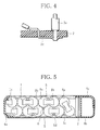
- FIG. 5 is a transverse cross-sectional view of a modified battery pack
- FIG. 6 is a perspective view of an electronic device incorporating a backup power supply device according to the present invention.
- FIG. 7 is an exploded perspective view of a backup power supply device according to the present invention.
- FIG. 8 is a transverse cross-sectional view of the backup power supply device shown in FIG. 7;
- FIG. 9 is a perspective view of a display unit incorporated in a front panel of the backup power supply device shown in FIG. 7;
- FIG. 10A is a fragmentary cross-sectional view of a first structure for the display unit shown in FIG. 9;
- FIG. 10B is a fragmentary cross-sectional view of a second structure for the display unit shown in FIG. 9;
- FIG. 10C is a fragmentary cross-sectional view of a third structure for the display unit shown in FIG. 9;
- FIG. 11 is a front elevational view of a plurality of display elements on the front panel of the backup power supply device shown in FIG. 7;
- FIG. 12 is a view showing charged/discharged states of rechargeable batteries and a plurality of charged levels thereof which are displayed by the display elements;
- FIG. 13 is a view showing charged/discharged states of rechargeable batteries and a plurality of charged levels thereof in another pattern which are displayed by the display unit.
- a battery pack for use as a backup power supply device for electronic devices of one embodiment according to the present invention will be described below with reference to the drawings.
- FIG. 1 is an exploded perspective view of a battery pack according to the present invention.
- the battery pack has a rechargeable battery group 1 comprising a plurality of cylindrical rechargeable batteries 1 a connected in series and arranged in a horizontal flat planar block.
- each of the rechargeable batteries 1 a comprises an AA-size nickel-metal hydrid rechargeable battery, for example.
- the rechargeable batteries 1 a are oriented or their electrodes are oriented in alternately different directions.
- the rechargeable batteries 1 a are arranged in two horizontal arrays, each having six rechargeable batteries 1 a which are connected in series by electrode connectors 1 b spot-welded to the electrodes of the rechargeable batteries 1 a .
- the two arrays of rechargeable batteries 1 a are oriented in the same direction and juxtaposed in a plane, and connected in series at one end thereof by a long electrode connector 1 c whose opposite ends are bent at a right angle.
- the rechargeable battery group 1 is constructed as a flat planar block of series-connected twelve rechargeable batteries 1 a arranged in two juxtaposed horizontal arrays each comprising six rechargeable batteries 1 a.
- a circuit board 2 supports thereon an electronic circuit assembly which is packed together with the rechargeable battery group 1 .
- the electronic circuit assembly mounted on the circuit board 2 comprises a charging control module 2 a for controlling the charging of the rechargeable battery group 1 , a battery temperature detecting module 2 b for detecting the temperature of the rechargeable battery group 1 , and a charged energy detecting module 2 c for determining a charged energy in the rechargeable battery group 1 .
- the circuit board 2 is disposed in confronting relation to an end of the rechargeable battery group 1 in the form of the flat planar block.
- the circuit board 2 comprises an elongate rectangular printed-wiring board which is of substantially the same size as the end of the rechargeable battery group 1 .
- the circuit board 2 has a shorter side having a length which is essentially the same as the diameter of the rechargeable batteries 1 a and a longer side having a length which is essentially the same as twice the length of the rechargeable batteries 1 a.
- the circuit board 2 is positioned adjacent to the end of the rechargeable battery group 1 and connected to the electrodes of the rechargeable battery group 1 . From the circuit board 2 , there extend a pair of power supply wires 3 a for charging and discharging the rechargeable battery group 1 and signal wires 3 b , 3 c for outputting signals representing states of the rechargeable battery group 1 which are detected by the electronic circuit assembly on the circuit board 2 .
- the signals representing states of the rechargeable battery group 1 represent information of the battery temperature detected by the battery temperature detecting module 2 b , a control signal for operating a cooling fan, described later, depending on the battery temperature, and information of a charged energy in the rechargeable battery group 1 which is detected by the charged quantity detecting module 2 c.
- the circuit board 2 and the rechargeable battery group 1 are packed together as follows: Basically, the rechargeable battery group 1 and the circuit board 2 are placed in a battery case 4 .
- the battery case 4 of this embodiment has two heat radiating plates 5 vertically sandwiching and held against the upper and lower surfaces of the rechargeable batteries 1 a which make up the rechargeable battery group 1 in the form of the flat planar block.
- the battery case 4 is arranged to support the heat radiating plates 5 that are exposed to the exterior and accommodate the rechargeable battery group 1 and the circuit board 2 therein.
- the heat radiating plates 5 comprise aluminum plates or the like of good thermal conductivity and have recesses 5 a , 5 b defined in inner surfaces thereof that are held against the rechargeable battery group 1 a and having arcuate surfaces along circumferential surfaces of the rechargeable batteries 1 a .
- the heat radiating plates 5 have exposed flat outer surfaces having a plurality of grooves 5 c positioned between the recesses 5 a , 5 b and in thicker regions which are disposed between adjacent ones of the rechargeable batteries 1 a that are arrayed horizontally.
- the grooves 5 c extend in the direction of the arrays of the rechargeable batteries 1 a .
- the exposed flat outer surfaces of the heat radiating plates 5 include outer wall ridges disposed between the grooves 5 c which serve as heat radiating fins 5 d with increased surface areas.
- the heat radiating plates 5 have central recesses 5 b defined in their inner surfaces which have a width twice the width of the recesses 5 a so as to extend over two rechargeable batteries 1 a .
- the wider recesses 5 b provide gaps between their flat central bottoms and the circumferential surfaces of the rechargeable batteries 1 a , the gaps serving as an installation space for accommodating a temperature sensor 6 that is mounted in a central region of one of the arrays of rechargeable batteries 1 a.
- the two heat radiating plates 5 sandwich the upper and lower arranged surfaces of the rechargeable batteries 1 a which make up the rechargeable battery group 1 and have their inner surfaces held in abutment against the circumferential surfaces of the rechargeable batteries 1 a .
- the battery case 4 accommodates therein the rechargeable battery group 1 and the circuit board 2 between the heat radiating plates 5 with their outer surfaces exposed to the exterior.
- the battery case 4 also has a pair of L-shaped battery holders 4 a fitted over respective opposite sides of the rechargeable battery group 1 and covering peripheral regions including an end and sides of the rechargeable battery group 1 , and board holders 4 b , 4 c positioning the circuit board 2 at the other end of the rechargeable battery group 1 and joined to the battery holders 4 a in covering relation to the circuit board 2 .
- the board holders 4 b , 4 c are vertically separated from each other, and have holes defined therebetween through which the power supply wires 3 a and the signal wires 3 b , 3 c extend from the circuit board 2 .
- the board holders 4 b , 4 c are integrally united to each other and joined to the battery holders 4 a.
- the upper and lower heat radiating plates 5 cover the surfaces of the twelve rechargeable batteries 1 a arranged in two juxtaposed horizontal arrays in the form of the flat planar block, and have their inner surfaces held in contact with the circumferential surfaces of the rechargeable batteries 1 a . Since the outer surfaces of the heat radiating plates 5 are exposed, they can effectively radiate heat generated by the rechargeable batteries 1 a .
- the heat radiating efficiency of the heat radiating plates 5 is high because of the heat radiating fins 5 d formed on the outer surfaces of the heat radiating plates 5 .
- the battery pack is in the shape of a flat rectangular parallelepiped in its entirety with the rechargeable battery group 1 whose upper and lower surfaces are covered with the heat radiating plates 5 and whose sides are covered with the battery case 4 , the battery pack is of a compact form that can easily be handled.
- the power supply wires 3 a and the signal wires 3 b , 3 c from the circuit board 2 can also be handled with ease as they extend together through the board holders 4 b , 4 c.
- the two power supply wires 3 a used to charge and discharge the rechargeable battery group 1 extend from opposite sides of the circuit board 2 .
- One of the power supply wires 3 a extends from one side to the other in the battery case 4 , and the two power supply wires 3 a are put together and extend through the board holders 4 b , 4 c . Therefore, the power supply wires 3 a can also be handled with utmost ease.
- Each of the power supply wires 3 a has a thick core for allowing a large current to pass therethrough.
- the power supply wires 3 a can easily be laid in the battery case 4 because they are guided by bosses 4 d projecting in the battery case 4 . Accordingly, the power supply wires 3 a can be held stably in position under high tensile strength.
- Each of the power supply wires 3 a is connected to the circuit board 2 by soldering as follows: As shown in FIG. 4, a separate tab 2 e is mounted in the circuit board 2 , and the power supply wire 3 a is extended through a hole in the circuit board 2 and soldered to the tab 2 e on the reverse side of the circuit board 2 . Since the power supply wire 3 a is held by the circuit board 2 , the power supply wire 3 a can be connected to the tab 2 e with increased strength even when the power supply wire 3 a is thick and hard, and can be stably soldered even when a large amount of heat is applied in the soldering process.
- the battery pack has been described as a flat compact battery pack comprising horizontal arrays of AA-type nickel-hydrogen cells.
- the battery pack may further be constructed into a lower profile by using AAA-type nickel-metal hydrid rechargeable batteries.
- the battery pack may be of a 1U size that can be incorporated in a standard rack.
- the rechargeable battery group 1 comprises twelve rechargeable batteries 1 a connected in series together, the rechargeable battery group 1 may comprise a plurality of rechargeable batteries 1 a connected in both series and parallel depending on the battery specification requirements (battery voltage, battery capacity, etc.).
- the shape of the heat radiating plates 5 and the functions of the electronic circuit may also be changed depending on the battery specification requirements.
- FIG. 5 shows a modified battery pack in transverse cross section.
- the modified battery pack has two layers of a horizontal array of rechargeable batteries 1 a which are connected in both series and parallel into a rechargeable battery group 1 for an increased battery capacity. Since the circumferential surfaces of each of the rechargeable batteries 1 a in the two layers are necessarily held in contact with one of the upper and lower heat radiating plates 5 , the heat generated by each of the rechargeable batteries 1 a is effectively radiated via the heat radiating plates 5 .
- the rechargeable batteries 1 a in one of the two layers are displaced from the rechargeable batteries 1 a in the other of the two layers by a distance which is half the pitch between adjacent rechargeable batteries 1 a . Consequently, the modified battery pack has a thickness that is smaller than twice the diameter of each of the rechargeable batteries 1 a .
- the battery pack with the two layers of rechargeable batteries 1 a has a relatively small thickness and hence is of a relatively low profile.
- a computer or server which is an electronic device energized by a commercial power supply as a drive source has a main unit 11 and a power supply 12 which are incorporated in a casing 10 in the form of a mini tower.
- the housing 10 also accommodates therein a CD drive 13 in a drive bay and a peripheral unit (not shown) such as a hard disk drive or the like.
- a backup power supply device for backing up operation of the electronic device supplies electric power to the main unit 11 , not from the power supply 12 , to ensure its continued operation over a predetermined period of time in the event of a failure of the power supply 12 due to a commercial power system fault or power service interruption.
- the backup power supply device has rechargeable batteries which are charged by electric power supplied from the power supply 12 . When the power supply 12 fails to function, the backup power supply device discharges the electric power stored in the rechargeable batteries via the power supply 12 to the main unit 11 .
- a backup power supply device 14 (see FIG. 6) according to the present invention comprises a battery pack 20 (see FIG. 7) as the rechargeable batteries referred to above. As shown in FIG. 6, the backup power supply device 14 has a case mounted in a drive bay for 3.5-inch floppy disks in the housing 10 , with the battery pack 20 housed in the case.
- the battery pack 20 of the backup power supply device 14 comprises a rechargeable battery group 1 having a plurality of series-connected rechargeable batteries as described above and an electronic circuit 2 for controlling the charging and discharging of the rechargeable batteries.
- the rechargeable battery group 1 and the electronic circuit 2 are accommodated in a battery case 4 .
- the battery pack 20 is in the shape of a flat planar block.
- the battery pack 20 is housed in a box-shaped case 30 having a size that can be mounted in the drive for 3.5-inch floppy disks.
- the case 30 comprises a chassis 31 of aluminum having a bottom panel 31 a , side panels 31 b and a rear panel 31 c , a lid 32 as an upper panel covering the chassis 31 , and a front panel 33 of plastics mounted on the front end of the chassis 31 .
- the side panels 31 b have upper ends stepped inwardly toward each other.
- the lid 32 has peripheral flanges fitted over the outer sides of the stepped upper ends of the side panels 31 b , so that the chassis 31 and the lid 32 are joined to each other with smooth flat outer surfaces on their sides.
- the chassis 31 supports thereon a cooling fan 40 positioned near the rear panel 31 c for passing air through the case 30 .
- the bottom panel 31 a supports on a rear upper surface thereof a circuit board 41 which supports thereon a fan control circuit for controlling operation of the cooling fan 40 .
- a connector 42 for inputting and outputting various control signals is mounted on the circuit board 41 and exposed through an opening defined in the rear panel 31 c for connection to external circuits.
- the front panel 33 has a plurality of display elements such as light-emitting diodes or the like for displaying operating states of the backup power supply device.
- a display control circuit board (not shown) for selectively energizing the display elements is supported on the rear surface of the front panel 33 .
- the selective energization of the display elements with the display control circuit board is controlled by information indicative of states of the rechargeable batteries which is given from the battery pack 20 .
- the display elements are selectively energized to display a charged quantity of electric energy (charged energy) in the rechargeable battery group 1 , charged/discharged states of the rechargeable battery group 1 , and a faulty state thereof.
- the backup power supply device with the battery pack 20 housed in the case 30 as described above has the following features: As shown in FIG. 7, the bottom panel 31 a of the chassis 31 has a plurality of truncated conical burrs 35 of a given height projecting upwardly into the case 30 .
- the burrs 35 have holes 36 defined respectively in their upper ends.
- the burrs 35 serve to support the battery pack 20 spaced from the bottom panel 31 a by a certain gap. Screws 37 on the reverse side of the bottom panel 31 a are inserted through the respective holes 36 in the burrs 35 and threaded into internally threaded holes 5 e defined in the lower heat radiating plate 5 of the battery pack 20 , thus fastening the battery pack 20 to the bottom panel 31 a.
- the internally threaded holes 5 e are defined in the lower heat radiating plate 5 at given positions, but do not extend through the lower heat radiating plate 5 .
- the burrs 35 are positioned depending on the position where the battery pack 20 is housed, and are aligned with the respective internally threaded holes 5 e defined in the lower heat radiating plate 5 .
- the burrs 35 have a height selected such that when the lid 32 is attached in covering relation to the battery pack 20 fixed to the bottom plate 31 a , a certain gap is created between the inner surface of the lid 32 and the upper surface of the battery pack 20 .
- a bridge-like projection 38 is formed by partly cutting off a front central end portion of the bottom panel 31 a .
- the projection 38 provides an air passage between itself and the bottom panel 31 a , and is held against the front end of the battery pack 20 housed in the chassis 31 thereby positioning the battery pack 20 in place.
- the cooling fan 40 when the cooling fan 40 is energized to draw air from the case 30 , fresh external air is introduced through the air passage defined by the projection 38 into the case 30 .
- the introduced air flows through the gap between the lower heat radiating plate 5 and the bottom panel 31 a and also through the gap between the upper heat radiating plate 5 and the lid 32 , and is then discharged out of the case 30 by the cooling fan 40 .
- the heat radiating plates 5 are efficiently cooled by the flowing air, and the heat of the battery pack 20 is discharged to reduce a temperature rise of the rechargeable battery group 1 . Since the air flows along the heat radiating fins 5 d on the outer surfaces of the heat radiating plates 5 , the heat radiating effect thereof is increased.
- the air passage defined by the projection 38 is positioned in the space in the housing 10 . Therefore, air is supplied from the space in the housing 10 into the case 30 through the air passage, and hence external air laden with dust and dirt particles around the housing 10 is prevented from being directly introduced into the case 30 . Consequently, the interior of the backup power supply device is effectively protected against contamination by the external air which carries undesirable contaminants.
- the chassis 31 of aluminum and the lower heat radiating plate 5 in the form of an aluminum die casting are directly connected to each other by the burrs 35 and the screws 37 , heat can be conducted well between the chassis 31 and the heat radiating plate 5 .
- the chassis 31 itself can function as a heat radiator to provide an increased heat radiating capability for the rechargeable battery group 1 .
- Externally applied heat is absorbed by the heat radiating plates 5 and the chassis 31 that are thermally coupled to each other, so that the rechargeable battery group 1 is prevented from suffering a local temperature rise thereby protecting the rechargeable batteries 1 a from unwanted thermal unbalance.
- the backup power supply device can effectively function to ensure operation of the electronic device 11 upon a power failure simply by installing the backup power supply device in the drive bay of the housing 10 and connecting the power supply wires 3 a to the power supply 12 . Therefore, the backup power supply device can be handled with utmost ease. Inasmuch as the backup power supply device is placed in the housing 10 and used with the electronic device 11 , the backup power supply device is free of any problems due to the lack of an installation space which would otherwise occur in a large-size no-break power unit incorporating a conventional lead storage battery.
- a display unit combined with the front panel 33 of the case 30 comprises a circuit board 52 supporting thereon a plurality of display elements 51 in the form of light-emitting diodes or the like and a display control circuit for selectively energizing the display elements 51 .
- the signal wire 3 c extending from the battery pack 20 is connected to the circuit board 52 to supply information representing a charged energy in the rechargeable battery group 1 and other information to the display control circuit.
- the display control circuit selectively energizes the display elements 51 according to the information given from the battery pack 20 to display a charged energy in the rechargeable battery group 1 , charged/discharged states of the rechargeable battery group 1 , and a faulty state thereof.
- the front panel 33 has a long horizontal groove 33 a defined in its front surface to divide the front surface into upper and lower regions and a slit 33 b extending transversely in and along the groove 33 a .
- a transparent panel 34 is mounted on the rear surface of the front panel 33 and has a long horizontal protrusion 34 a projecting on a front surface thereof and fitted in the slit 33 b .
- the circuit board 52 with the display elements (light-emitting diodes) 51 and the display control circuit supported thereon is disposed behind the transparent panel 34 .
- the display elements or light-emitting diodes 51 comprise semiconductor chips mounted directly on the circuit board 52 , and are arranged in an array extending along the slit 33 b in the front panel 33 .
- the transparent panel 34 functions as a light guide for guiding light emitted from the display elements (light-emitting diodes) 51 to the front surface of the front panel 33 .
- the transparent panel 34 has a rear surface coated with a light-shielding coating layer (light-shielding member) 35 except for an area directly facing the display elements 51 . Therefore, the transparent panel 34 guides only light incident on the uncoated area to the front surface of the front panel 33 .
- the transparent panel 34 thus guides only light emitted from the light-emitting diodes 51 from the uncoated area (light inlet area) confronting the light-emitting diodes 51 , to the front surface of the front panel 33 .
- the display unit thus constructed resides in that, as shown FIGS. 10A, 10 B, and 10 C, the light inlet area of the transparent panel 34 which faces the light-emitting diodes 51 has a recess 36 (see FIGS. 10A and 10B) or a land 37 (see FIG. 10 C), and the light emitted from the light-emitting diodes 51 is introduced through the recess 36 or the land 37 and diffused into the transparent panel 34 as the light guide.
- the recess 36 has an arcuate surface as shown in FIG. 10A or a parabolic surface as shown in FIG. 10 B.
- the light-emitting diodes 51 have their light-emitting surfaces positioned at the center or focal point of the recess 36 .
- the light emitted in a spreading pattern from the light-emitting diodes 51 is introduced through the curved surface of the recess 36 and diffused into the transparent panel 34 . Then, the light is propagated through the transparent panel (light guide) 34 , and radiated in a wide spreading angle from the front surface of the transparent panel 34 .
- the land 37 on the transparent panel 34 as shown in FIG. 10C is positioned such that its distal end is close to the light-emitting surfaces of the light-emitting diodes 51 .
- the light emitted in a spreading pattern from the light-emitting diodes 51 is introduced into the transparent panel 34 while substantially keeping its spreading angle, and propagated through the transparent panel (light guide) 34 .
- the light is then radiated from the front and side surfaces of the transparent panel 34 .
- the light radiated from the transparent panel 34 can be visually recognized not only in the front direction of the display unit, but also in directions deviating from the front direction of the display unit.
- the backup power supply device with the display unit is mounted in the drive bay of the housing 1 and the display unit is positioned off the line of sight of the operator, the operator can easily and reliably visually perceive the light radiated from the transparent panel 34 .
- the visual recognition of the light radiated from the transparent panel 34 is enhanced simply by providing the recess 36 or the land 37 in the light inlet area of the transparent panel 34 which guides the light from the light-emitting diodes 51 .
- the curvature of the recess 36 or the height of the land 37 may be selected depending on the size of the light-emitting surfaces of the light-emitting diodes 51 .
- the elongate protrusion 34 a of the transparent panel 34 may have a flat surface or an appropriately curved surface on its distal end. The shape of the distal end of the elongate protrusion 34 a may be determined depending on the design of the front panel 33 .
- the display elements 51 of the display unit may comprise display elements other than light-emitting diodes, and the number of the display elements 51 is not limited to any numerical value.
- the display unit comprises a light-emitting diode (LED) 71 for displaying a charged energy in the rechargeable battery group 1 , five light-emitting diodes 72 , 73 , 74 , 75 , 76 for displaying charged/discharged states of the rechargeable battery group 1 in a plurality of levels, and a light-emitting diode 77 for displaying a faulty state of the rechargeable battery group 1 .
- LED light-emitting diode
- the light-emitting diodes 71 through 77 are selectively energized or flickered to display the charged quantity of the rechargeable battery group 1 , the charged/discharged states thereof, and the faulty states thereof.
- the five light-emitting diodes 72 , 73 , 74 , 75 , 76 serve to display the charged energy Cap of the rechargeable battery group 1 in five levels in terms of units of 20% with 100% representing the fully charged state.
- the light-emitting diode (LED) 71 comprises a light-emitting diode capable of emitting light in two colors, and emits light in one color depending on the charged or discharged state of the rechargeable battery group 1 .
- the light-emitting diode 71 displays the charged/discharged state of the rechargeable battery group 1 and the light-emitting diodes 72 , 73 , 74 , 75 , 76 display the charged quantity of the rechargeable battery group 1 , the operator can easily and accurately recognize the state of the rechargeable battery group 1 .
- the seven light-emitting diodes 71 through 77 display the state of the rechargeable battery group 1 in a pattern shown in FIG. 12, for example.
- the light-emitting diode 71 is energized to emit light in different colors depending on whether the rechargeable battery group 1 is being charged or discharged. For example, when the rechargeable battery group 1 is being charged, the light-emitting diode 71 is energized to emit green light indicating that the rechargeable battery group 1 is being charged. When the charging of the rechargeable battery group 1 is completed, the light-emitting diode 71 is de-energized (the green lighting is stopped). When the rechargeable battery group 1 is being discharged, the light-emitting diode 71 is energized to emit red light indicating that the rechargeable battery group 1 is being discharged.
- the light-emitting diodes 72 through 76 are selectively energized depending on the charged energy in the rechargeable battery group 1 . Specifically, when the charged energy Cap is 20% or less, only the light-emitting diode 72 is energized. When the charged energy Cap is in excess of 20% and equal to or less than 40%, the two light-emitting diodes 72 , 73 are energized for lighting. When the charged energy Cap is in excess of 40% and equal to or less than 60%, the three light-emitting diodes 72 , 73 , 74 are energized for lighting.
- the four light-emitting diodes 72 , 73 , 74 , 75 are energized for lighting.
- all the five light-emitting diodes 72 , 73 , 74 , 75 , 76 are energized for lighting.
- the light-emitting diode 71 indicative of the charged/discharged state is energized in a pattern different from the pattern at the time the rechargeable battery group 1 is being charged, so that the operator can judge when the rechargeable battery group 1 is being discharged from the energized pattern of the light-emitting diode 71 .
- the light-emitting diodes 72 through 76 are used to display the charged energy Cap of the rechargeable battery group 1 . Therefore, the operator can easily and accurately recognize the state of the rechargeable battery group 1 simply by seeing the energized states (display states) of the light-emitting diodes (display segments) 71 through 76 incorporated in the front panel 33 of the case 30 , and hence can confirm whether the backup power supply device or no-break power unit is functioning normally.
- the light-emitting diode 77 is energized to indicate a faulty state of the rechargeable battery group 1 , the operator can reliably recognize such a faulty state of the rechargeable battery group 1 and can take a quick action for recovery.
- the backup power supply device does not steadily supply electric energy from the rechargeable batteries to the electronic device 11 , but takes over the power supply 12 to supply electric energy from the rechargeable batteries to the electronic device 11 in the event of a fault failing to supply electric energy from the power supply 12 to the electronic device 11 . It is thus difficult to confirm whether the charging capability of the backup power supply device is functioning normally simply by displaying the charged quantity of the rechargeable batteries.
- the backup power supply device since the backup power supply device has the display segment (light-emitting diode 71 ) for displaying the charged/discharged state, the operator can immediately know when the rechargeable batteries start being charged from the energization of the light-emitting diode 71 at the time the backup power supply device is accommodated in the housing 10 .
- the operator can therefore easily and accurately confirm the charging capability of the backup power supply device.
- the light-emitting diode 71 is de-energized, allowing the operator to know that the rechargeable batteries are not in the charged/discharged state. Since the light-emitting diodes 72 through 76 are all energized, they indicate that the rechargeable batteries are in a standby state capable of backing up the electronic device 11 . Thus, the operator can reliably know that the rechargeable batteries are functioning properly.
- the light-emitting diodes 72 through 76 for displaying the charged quantity in a plurality of levels may be energized in different patterns when the rechargeable batteries are charged and discharged, as shown in FIG. 13 . Specifically, while the rechargeable batteries are being discharged, the light-emitting diodes 72 through 76 are flickered depending on the battery energy (charged quantity) Cap, clearly indicating that the rechargeable batteries are being discharged. At this time, the display segment (light-emitting diode 71 ) dedicated to the display of the charged/discharged state of the rechargeable batteries indicates that the rechargeable batteries are being discharged. Accordingly, the operator does not overlook the display pattern of the flickering light-emitting diodes 72 through 76 .
- those light-emitting diodes which correspond to already charged levels may be energized, and the light-emitting diode which corresponds to a presently charged level may be flickered to display the charged energy Cap.
- the light-emitting diode which corresponds to the level of the charged energy Cap may be flickered, and those light-emitting diodes which correspond to the levels lower than the presently charged level may be continuously energized.
- This display pattern allows the operator to distinguish the already achieved charged quantity and the presently charged quantity from each other, so that the operator can recognize the charged energy Cap more accurately.
- the battery pack which is of a flat compact shape and can easily be handled according to the present invention, offers various practical advantages.
Abstract
A battery pack for use as a backup power supply device for various electronic devices has a rechargeable battery group having a plurality of cylindrical rechargeable batteries connected in series and/or parallel and arranged in horizontal flat arrays as a flat block, and an electronic circuit for controlling charging of the rechargeable battery group. Two heat radiating plates sandwich opposite surfaces of the rechargeable batteries of the rechargeable battery group and are held against circumferential surfaces of the rechargeable batteries. A battery case houses an electronic circuit positioned at an end in the direction of the arrays of the rechargeable batteries and surrounds the rechargeable battery group to accommodate them therein. The battery case supports the heat radiating plates so as to be exposed to the exterior. The battery pack is compact and free of thermal problems with the rechargeable batteries.
Description
1. Field of the Invention
The present invention relates to a battery pack with a compact configuration for use as a drive source or backup power supply device for various electronic devices, and a backup power supply device with such a battery pack.
2. Description of the Prior Art
Attention has been directed to the importance of backup power supplies for supplying electric power to an electronic device, not from its own power supply, to ensure its continued operation in the event of a failure of the device power supply which supplies power to various electronic devices due to a power system fault or power service interruption. Such a kind of backup power supply comprises rechargeable batteries which are charged by the electric power supplied from the device power supply, and, when the device power supply fails to function, discharges and supplies the stored electric energy to the electronic device. Heretofore, as the rechargeable batteries, lead cells having a large capacity have solely been used. Recently, attempts have been made to use nickel-metal hydrid rechargeable batteries or lithium-ion rechargeable batteries.
Rechargeable batteries have their battery characteristics greatly variable depending on the battery temperature. Further, it cannot be denied that rechargeable batteries themselves generate heat when they are charged and discharged. Consequently, any backup power supply devices employing rechargeable batteries require some thermal measures to be incorporated therein. If such a backup power supply device is mounted in a casing which houses an electronic device, then the heat generated by the electronic device may be applied directly to the backup power supply device depending on the location of the backup power supply device in the casing. It is thus necessary to position the backup power supply device in the casing in a layout designed with thermal considerations.
However, the tendency of recent electronic devices which are smaller-sized and are made up of highly packed components may possibly limit significantly the location of the backup power supply device. One solution is to place a backup power supply device in a drive bay that is provided for installing an external unit (auxiliary unit) in a box-shaped casing which houses an electronic device. In this case, however, using the drive bay to accommodate the backup power supply device leaves certain problems unsolved as to how to make the backup power supply device compact enough to be fitted in the drive bay while at the same time combining itself with thermal precautions. Moreover, in general, a hard disk drive is frequently positioned below the drive bay of the casing. Since the hard disk acts as a large heat source, the backup power supply device needs to have an additional thermal protection scheme.
It is therefore an object of the present invention to provide a battery pack for use as a drive source or backup power supply device for various electronic devices, which is designed to effectively solve problems of heat generated by rechargeable batteries and thermal problems imposed by external sources and also to be compact.
Another object of the present invention to provide a backup power supply device of compact configuration for use in a drive bay of a casing which accommodates an electronic device, for example, therein.
A battery pack according to the present invention has a rechargeable battery group having a plurality of rechargeable batteries connected in series and/or parallel and arranged in horizontal flat arrays as a flat block, an electric circuit for controlling charging of the rechargeable battery group, two heat radiating plates sandwiching opposite surfaces of the rechargeable batteries of the rechargeable battery group, and a battery case supporting the heat radiating plates so as to be exposed, the electronic circuit and the rechargeable battery group being housed in the battery case with the electronic circuit being positioned at an end of the battery case in the direction of the arrays of the rechargeable batteries.
Preferably, the rechargeable batteries comprise cylindrical nickel-metal hydrid rechargeable batteries arranged in two horizontal flat arrays and connected in series. Each of the heat radiating plates has arcuate recesses defined in a surface thereof held against the cylindrical rechargeable batteries and extending along circumferential surfaces of the cylindrical rechargeable batteries. Each of the heat radiating plates has a flat surface exposed out of the battery case. Each of the heat radiating plates has a surface exposed out of the battery case and having a plurality of grooves defined in regions positioned between adjacent ones of the rechargeable batteries arranged in horizontal flat arrays, the grooves extending in the direction of the arrays of the rechargeable batteries, with regions between the grooves serving as heat radiating fins.
The battery pack further includes power supply wires for charging and discharging the rechargeable batteries and signal wires extending from the electronic circuit, the battery case having an end close to the electronic circuit, the power supply wires and the signal wires extending out of the battery case from the end thereof. Further, the electronic circuit desirably has a function to detect a temperature of the rechargeable batteries, and a function to detect a charged energy of the rechargeable batteries, besides its function to control charging of the rechargeable batteries.
According to the present invention, a battery pack of a flat compact shape can be realized and further it has a structure with an excellent heat radiation capability for effectively radiating heat generated by the rechargeable batteries. The battery pack is thus capable of sufficiently performing rechargeable battery functions, and can easily be handled.
A backup power supply device according to the present invention has the battery pack described above, a case for being mounted in a drive bay in a housing which incorporates an electronic device therein, the battery pack being housed in the case. The backup power supply device is arranged to charge the rechargeable batteries of the battery pack with electric energy supplied from a power supply of the electronic device, and supply electric energy from the rechargeable batteries to the electronic device upon a failure of electric energy supplied to the power supply.
In one preferred embodiment of the present invention, the case has a support supporting the battery pack with a gap defined between an inner surface of the case and the heat radiating plates of the battery pack. The support comprises a burr of a predetermined height projecting from a bottom panel of the case into the case, one of the heat radiating plates being fastened to the bottom panel by a screw threaded through the burr into the one of the heat radiating plates.
The backup power supply device further includes a cooling fan disposed in the case at a rear panel thereof for passing air through the case. The case has an air inlet defined in a front bottom panel thereof for introducing air into the case. The cooling fan is energized to discharge air out of the case when the rechargeable batteries are subject to a temperature rise.
According to the backup power supply device with the above-mentioned configuration of the present invention, since air can effectively flows through the case which accommodates the battery pack therein, thermal problems with the battery pack can effectively be solved. The backup power supply device can be handled with ease because it has a compact low profile and is housed in the case that can be mounted in the drive bay in the housing which incorporates the electronic device therein.
The backup power supply device further includes a display unit mounted on a front panel of the case, the display unit comprising a plurality of selectively energizable display elements mounted on a circuit board disposed behind the front panel, and a light guide of a transparent member mounted in the front panel for guiding light emitted from the display elements to a surface of the front panel, the transparent light guide having a light inlet area facing the display elements and a recess or land in the light inlet area for diffusing and introducing the light emitted from the display elements into the transparent light guide.
Preferably, the transparent light guide comprises a panel having an elongate protrusion fitted in a slit extending transversely in the front panel, the panel having a reverse surface confronting the display elements and coated with a light-shielding member except for the light inlet area. The display unit comprises a plurality of display elements for displaying a charged/discharged state of the rechargeable batteries.
According to the backup power supply device having such a display unit, the visual recognition of the display unit is sufficiently enhanced, and an operating state of the backup power supply device can accurately be displayed regardless of the location of the backup power supply device and hence of the location of the housing of the electronic device which incorporates the backup power supply device.
FIG. 1 is an exploded perspective view of a battery pack according to the present invention;
FIG. 2 is a plan view, partly broken away, of the battery pack shown in FIG. 1;
FIG. 3 is a transverse cross-sectional view of the battery pack shown in FIG. 1;
FIG. 4 is a cross-sectional view showing a structure by which a power supply wire of the battery pack shown in FIG. 1 and a circuit board are connected to each other;
FIG. 5 is a transverse cross-sectional view of a modified battery pack;
FIG. 6 is a perspective view of an electronic device incorporating a backup power supply device according to the present invention;
FIG. 7 is an exploded perspective view of a backup power supply device according to the present invention;
FIG. 8 is a transverse cross-sectional view of the backup power supply device shown in FIG. 7;
FIG. 9 is a perspective view of a display unit incorporated in a front panel of the backup power supply device shown in FIG. 7;
FIG. 10A is a fragmentary cross-sectional view of a first structure for the display unit shown in FIG. 9;
FIG. 10B is a fragmentary cross-sectional view of a second structure for the display unit shown in FIG. 9;
FIG. 10C is a fragmentary cross-sectional view of a third structure for the display unit shown in FIG. 9;
FIG. 11 is a front elevational view of a plurality of display elements on the front panel of the backup power supply device shown in FIG. 7;
FIG. 12 is a view showing charged/discharged states of rechargeable batteries and a plurality of charged levels thereof which are displayed by the display elements; and
FIG. 13 is a view showing charged/discharged states of rechargeable batteries and a plurality of charged levels thereof in another pattern which are displayed by the display unit.
A battery pack for use as a backup power supply device for electronic devices of one embodiment according to the present invention will be described below with reference to the drawings.
FIG. 1 is an exploded perspective view of a battery pack according to the present invention. As shown in FIG. 1, the battery pack has a rechargeable battery group 1 comprising a plurality of cylindrical rechargeable batteries 1 a connected in series and arranged in a horizontal flat planar block.
Specifically, each of the rechargeable batteries 1 a comprises an AA-size nickel-metal hydrid rechargeable battery, for example. The rechargeable batteries 1 a are oriented or their electrodes are oriented in alternately different directions. The rechargeable batteries 1 a are arranged in two horizontal arrays, each having six rechargeable batteries 1 a which are connected in series by electrode connectors 1 b spot-welded to the electrodes of the rechargeable batteries 1 a. The two arrays of rechargeable batteries 1 a are oriented in the same direction and juxtaposed in a plane, and connected in series at one end thereof by a long electrode connector 1 c whose opposite ends are bent at a right angle. An insulator (not shown) is interposed between the two arrays of rechargeable batteries 1 a to prevent a short circuit between confronting electrodes thereof. As a result, the rechargeable battery group 1 is constructed as a flat planar block of series-connected twelve rechargeable batteries 1 a arranged in two juxtaposed horizontal arrays each comprising six rechargeable batteries 1 a.
A circuit board 2 supports thereon an electronic circuit assembly which is packed together with the rechargeable battery group 1. The electronic circuit assembly mounted on the circuit board 2 comprises a charging control module 2 a for controlling the charging of the rechargeable battery group 1, a battery temperature detecting module 2 b for detecting the temperature of the rechargeable battery group 1, and a charged energy detecting module 2 c for determining a charged energy in the rechargeable battery group 1. The circuit board 2 is disposed in confronting relation to an end of the rechargeable battery group 1 in the form of the flat planar block. The circuit board 2 comprises an elongate rectangular printed-wiring board which is of substantially the same size as the end of the rechargeable battery group 1. Specifically, the circuit board 2 has a shorter side having a length which is essentially the same as the diameter of the rechargeable batteries 1 a and a longer side having a length which is essentially the same as twice the length of the rechargeable batteries 1 a.
The circuit board 2 is positioned adjacent to the end of the rechargeable battery group 1 and connected to the electrodes of the rechargeable battery group 1. From the circuit board 2, there extend a pair of power supply wires 3 a for charging and discharging the rechargeable battery group 1 and signal wires 3 b, 3 c for outputting signals representing states of the rechargeable battery group 1 which are detected by the electronic circuit assembly on the circuit board 2. The signals representing states of the rechargeable battery group 1 represent information of the battery temperature detected by the battery temperature detecting module 2 b, a control signal for operating a cooling fan, described later, depending on the battery temperature, and information of a charged energy in the rechargeable battery group 1 which is detected by the charged quantity detecting module 2 c.
The circuit board 2 and the rechargeable battery group 1 are packed together as follows: Basically, the rechargeable battery group 1 and the circuit board 2 are placed in a battery case 4. The battery case 4 of this embodiment has two heat radiating plates 5 vertically sandwiching and held against the upper and lower surfaces of the rechargeable batteries 1 a which make up the rechargeable battery group 1 in the form of the flat planar block. The battery case 4 is arranged to support the heat radiating plates 5 that are exposed to the exterior and accommodate the rechargeable battery group 1 and the circuit board 2 therein.
As shown in FIGS. 1 through 3, the heat radiating plates 5 comprise aluminum plates or the like of good thermal conductivity and have recesses 5 a, 5 b defined in inner surfaces thereof that are held against the rechargeable battery group 1 a and having arcuate surfaces along circumferential surfaces of the rechargeable batteries 1 a. The heat radiating plates 5 have exposed flat outer surfaces having a plurality of grooves 5 c positioned between the recesses 5 a, 5 b and in thicker regions which are disposed between adjacent ones of the rechargeable batteries 1 a that are arrayed horizontally. The grooves 5 c extend in the direction of the arrays of the rechargeable batteries 1 a. The exposed flat outer surfaces of the heat radiating plates 5 include outer wall ridges disposed between the grooves 5 c which serve as heat radiating fins 5 d with increased surface areas.
The heat radiating plates 5 have central recesses 5 b defined in their inner surfaces which have a width twice the width of the recesses 5 a so as to extend over two rechargeable batteries 1 a. The wider recesses 5 b provide gaps between their flat central bottoms and the circumferential surfaces of the rechargeable batteries 1 a, the gaps serving as an installation space for accommodating a temperature sensor 6 that is mounted in a central region of one of the arrays of rechargeable batteries 1 a.
The two heat radiating plates 5 sandwich the upper and lower arranged surfaces of the rechargeable batteries 1 a which make up the rechargeable battery group 1 and have their inner surfaces held in abutment against the circumferential surfaces of the rechargeable batteries 1 a. In this manner, the battery case 4 accommodates therein the rechargeable battery group 1 and the circuit board 2 between the heat radiating plates 5 with their outer surfaces exposed to the exterior.
The battery case 4 also has a pair of L-shaped battery holders 4 a fitted over respective opposite sides of the rechargeable battery group 1 and covering peripheral regions including an end and sides of the rechargeable battery group 1, and board holders 4 b, 4 c positioning the circuit board 2 at the other end of the rechargeable battery group 1 and joined to the battery holders 4 a in covering relation to the circuit board 2. The board holders 4 b, 4 c are vertically separated from each other, and have holes defined therebetween through which the power supply wires 3 a and the signal wires 3 b, 3 c extend from the circuit board 2. The board holders 4 b, 4 c are integrally united to each other and joined to the battery holders 4 a.
As shown in FIGS. 2 and 3 where the battery pack is shown in a plan view, partly broken away and in a transverse cross-sectional view, respectively, the upper and lower heat radiating plates 5 cover the surfaces of the twelve rechargeable batteries 1 a arranged in two juxtaposed horizontal arrays in the form of the flat planar block, and have their inner surfaces held in contact with the circumferential surfaces of the rechargeable batteries 1 a. Since the outer surfaces of the heat radiating plates 5 are exposed, they can effectively radiate heat generated by the rechargeable batteries 1 a. The heat radiating efficiency of the heat radiating plates 5 is high because of the heat radiating fins 5 d formed on the outer surfaces of the heat radiating plates 5.
Since the battery pack is in the shape of a flat rectangular parallelepiped in its entirety with the rechargeable battery group 1 whose upper and lower surfaces are covered with the heat radiating plates 5 and whose sides are covered with the battery case 4, the battery pack is of a compact form that can easily be handled. The power supply wires 3 a and the signal wires 3 b, 3 c from the circuit board 2 can also be handled with ease as they extend together through the board holders 4 b, 4 c.
As shown in FIG. 2, the two power supply wires 3 a used to charge and discharge the rechargeable battery group 1 extend from opposite sides of the circuit board 2. One of the power supply wires 3 a extends from one side to the other in the battery case 4, and the two power supply wires 3 a are put together and extend through the board holders 4 b, 4 c. Therefore, the power supply wires 3 a can also be handled with utmost ease. Each of the power supply wires 3 a has a thick core for allowing a large current to pass therethrough. The power supply wires 3 a can easily be laid in the battery case 4 because they are guided by bosses 4 d projecting in the battery case 4. Accordingly, the power supply wires 3 a can be held stably in position under high tensile strength.
Each of the power supply wires 3 a is connected to the circuit board 2 by soldering as follows: As shown in FIG. 4, a separate tab 2 e is mounted in the circuit board 2, and the power supply wire 3 a is extended through a hole in the circuit board 2 and soldered to the tab 2 e on the reverse side of the circuit board 2. Since the power supply wire 3 a is held by the circuit board 2, the power supply wire 3 a can be connected to the tab 2 e with increased strength even when the power supply wire 3 a is thick and hard, and can be stably soldered even when a large amount of heat is applied in the soldering process.
The battery pack has been described as a flat compact battery pack comprising horizontal arrays of AA-type nickel-hydrogen cells. However, the battery pack may further be constructed into a lower profile by using AAA-type nickel-metal hydrid rechargeable batteries. In such a modification, the battery pack may be of a 1U size that can be incorporated in a standard rack. While in the illustrated embodiment the rechargeable battery group 1 comprises twelve rechargeable batteries 1 a connected in series together, the rechargeable battery group 1 may comprise a plurality of rechargeable batteries 1 a connected in both series and parallel depending on the battery specification requirements (battery voltage, battery capacity, etc.). The shape of the heat radiating plates 5 and the functions of the electronic circuit may also be changed depending on the battery specification requirements.
FIG. 5 shows a modified battery pack in transverse cross section. As shown in FIG. 5, the modified battery pack has two layers of a horizontal array of rechargeable batteries 1 a which are connected in both series and parallel into a rechargeable battery group 1 for an increased battery capacity. Since the circumferential surfaces of each of the rechargeable batteries 1 a in the two layers are necessarily held in contact with one of the upper and lower heat radiating plates 5, the heat generated by each of the rechargeable batteries 1 a is effectively radiated via the heat radiating plates 5. The rechargeable batteries 1 a in one of the two layers are displaced from the rechargeable batteries 1 a in the other of the two layers by a distance which is half the pitch between adjacent rechargeable batteries 1 a. Consequently, the modified battery pack has a thickness that is smaller than twice the diameter of each of the rechargeable batteries 1 a. The battery pack with the two layers of rechargeable batteries 1 a has a relatively small thickness and hence is of a relatively low profile.
As shown in FIG. 6, a computer or server which is an electronic device energized by a commercial power supply as a drive source has a main unit 11 and a power supply 12 which are incorporated in a casing 10 in the form of a mini tower. The housing 10 also accommodates therein a CD drive 13 in a drive bay and a peripheral unit (not shown) such as a hard disk drive or the like.
A backup power supply device for backing up operation of the electronic device supplies electric power to the main unit 11, not from the power supply 12, to ensure its continued operation over a predetermined period of time in the event of a failure of the power supply 12 due to a commercial power system fault or power service interruption. The backup power supply device has rechargeable batteries which are charged by electric power supplied from the power supply 12. When the power supply 12 fails to function, the backup power supply device discharges the electric power stored in the rechargeable batteries via the power supply 12 to the main unit 11.
A backup power supply device 14 (see FIG. 6) according to the present invention comprises a battery pack 20 (see FIG. 7) as the rechargeable batteries referred to above. As shown in FIG. 6, the backup power supply device 14 has a case mounted in a drive bay for 3.5-inch floppy disks in the housing 10, with the battery pack 20 housed in the case.
As shown in FIG. 7, the battery pack 20 of the backup power supply device 14 comprises a rechargeable battery group 1 having a plurality of series-connected rechargeable batteries as described above and an electronic circuit 2 for controlling the charging and discharging of the rechargeable batteries. The rechargeable battery group 1 and the electronic circuit 2 are accommodated in a battery case 4. The battery pack 20 is in the shape of a flat planar block. The battery pack 20 is housed in a box-shaped case 30 having a size that can be mounted in the drive for 3.5-inch floppy disks.
As shown in FIGS. 7 and 8, the case 30 comprises a chassis 31 of aluminum having a bottom panel 31 a, side panels 31 b and a rear panel 31 c, a lid 32 as an upper panel covering the chassis 31, and a front panel 33 of plastics mounted on the front end of the chassis 31. The side panels 31 b have upper ends stepped inwardly toward each other. The lid 32 has peripheral flanges fitted over the outer sides of the stepped upper ends of the side panels 31 b, so that the chassis 31 and the lid 32 are joined to each other with smooth flat outer surfaces on their sides.
The chassis 31 supports thereon a cooling fan 40 positioned near the rear panel 31 c for passing air through the case 30. The bottom panel 31 a supports on a rear upper surface thereof a circuit board 41 which supports thereon a fan control circuit for controlling operation of the cooling fan 40. A connector 42 for inputting and outputting various control signals is mounted on the circuit board 41 and exposed through an opening defined in the rear panel 31 c for connection to external circuits.
The front panel 33 has a plurality of display elements such as light-emitting diodes or the like for displaying operating states of the backup power supply device. A display control circuit board (not shown) for selectively energizing the display elements is supported on the rear surface of the front panel 33. The selective energization of the display elements with the display control circuit board is controlled by information indicative of states of the rechargeable batteries which is given from the battery pack 20. The display elements are selectively energized to display a charged quantity of electric energy (charged energy) in the rechargeable battery group 1, charged/discharged states of the rechargeable battery group 1, and a faulty state thereof.
The backup power supply device with the battery pack 20 housed in the case 30 as described above has the following features: As shown in FIG. 7, the bottom panel 31 a of the chassis 31 has a plurality of truncated conical burrs 35 of a given height projecting upwardly into the case 30. The burrs 35 have holes 36 defined respectively in their upper ends.
As shown in FIG. 8, the burrs 35 serve to support the battery pack 20 spaced from the bottom panel 31 a by a certain gap. Screws 37 on the reverse side of the bottom panel 31 a are inserted through the respective holes 36 in the burrs 35 and threaded into internally threaded holes 5 e defined in the lower heat radiating plate 5 of the battery pack 20, thus fastening the battery pack 20 to the bottom panel 31 a.
The internally threaded holes 5 e are defined in the lower heat radiating plate 5 at given positions, but do not extend through the lower heat radiating plate 5. The burrs 35 are positioned depending on the position where the battery pack 20 is housed, and are aligned with the respective internally threaded holes 5 e defined in the lower heat radiating plate 5. The burrs 35 have a height selected such that when the lid 32 is attached in covering relation to the battery pack 20 fixed to the bottom plate 31 a, a certain gap is created between the inner surface of the lid 32 and the upper surface of the battery pack 20.
As shown in FIG. 7, a bridge-like projection 38 is formed by partly cutting off a front central end portion of the bottom panel 31 a. The projection 38 provides an air passage between itself and the bottom panel 31 a, and is held against the front end of the battery pack 20 housed in the chassis 31 thereby positioning the battery pack 20 in place.
Thus, according to the backup power supply device in which the battery pack 20 is housed in the case 30 with the air passage formed by the projection 38, when the cooling fan 40 is energized to draw air from the case 30, fresh external air is introduced through the air passage defined by the projection 38 into the case 30. The introduced air flows through the gap between the lower heat radiating plate 5 and the bottom panel 31 a and also through the gap between the upper heat radiating plate 5 and the lid 32, and is then discharged out of the case 30 by the cooling fan 40. As a result, the heat radiating plates 5 are efficiently cooled by the flowing air, and the heat of the battery pack 20 is discharged to reduce a temperature rise of the rechargeable battery group 1. Since the air flows along the heat radiating fins 5 d on the outer surfaces of the heat radiating plates 5, the heat radiating effect thereof is increased.
When the backup power supply device is mounted in the drive bay in the housing 10, the air passage defined by the projection 38 is positioned in the space in the housing 10. Therefore, air is supplied from the space in the housing 10 into the case 30 through the air passage, and hence external air laden with dust and dirt particles around the housing 10 is prevented from being directly introduced into the case 30. Consequently, the interior of the backup power supply device is effectively protected against contamination by the external air which carries undesirable contaminants.
Since the chassis 31 of aluminum and the lower heat radiating plate 5 in the form of an aluminum die casting are directly connected to each other by the burrs 35 and the screws 37, heat can be conducted well between the chassis 31 and the heat radiating plate 5. As a result, the chassis 31 itself can function as a heat radiator to provide an increased heat radiating capability for the rechargeable battery group 1. Externally applied heat is absorbed by the heat radiating plates 5 and the chassis 31 that are thermally coupled to each other, so that the rechargeable battery group 1 is prevented from suffering a local temperature rise thereby protecting the rechargeable batteries 1 a from unwanted thermal unbalance.
The backup power supply device can effectively function to ensure operation of the electronic device 11 upon a power failure simply by installing the backup power supply device in the drive bay of the housing 10 and connecting the power supply wires 3 a to the power supply 12. Therefore, the backup power supply device can be handled with utmost ease. Inasmuch as the backup power supply device is placed in the housing 10 and used with the electronic device 11, the backup power supply device is free of any problems due to the lack of an installation space which would otherwise occur in a large-size no-break power unit incorporating a conventional lead storage battery.
As shown in FIG. 9, a display unit combined with the front panel 33 of the case 30 comprises a circuit board 52 supporting thereon a plurality of display elements 51 in the form of light-emitting diodes or the like and a display control circuit for selectively energizing the display elements 51. The signal wire 3 c extending from the battery pack 20 is connected to the circuit board 52 to supply information representing a charged energy in the rechargeable battery group 1 and other information to the display control circuit. The display control circuit selectively energizes the display elements 51 according to the information given from the battery pack 20 to display a charged energy in the rechargeable battery group 1, charged/discharged states of the rechargeable battery group 1, and a faulty state thereof.
More specifically, as shown in FIG. 9, the front panel 33 has a long horizontal groove 33 a defined in its front surface to divide the front surface into upper and lower regions and a slit 33 b extending transversely in and along the groove 33 a. A transparent panel 34 is mounted on the rear surface of the front panel 33 and has a long horizontal protrusion 34 a projecting on a front surface thereof and fitted in the slit 33 b. The circuit board 52 with the display elements (light-emitting diodes) 51 and the display control circuit supported thereon is disposed behind the transparent panel 34.
The display elements or light-emitting diodes 51 comprise semiconductor chips mounted directly on the circuit board 52, and are arranged in an array extending along the slit 33 b in the front panel 33. The transparent panel 34 functions as a light guide for guiding light emitted from the display elements (light-emitting diodes) 51 to the front surface of the front panel 33. The transparent panel 34 has a rear surface coated with a light-shielding coating layer (light-shielding member) 35 except for an area directly facing the display elements 51. Therefore, the transparent panel 34 guides only light incident on the uncoated area to the front surface of the front panel 33. The transparent panel 34 thus guides only light emitted from the light-emitting diodes 51 from the uncoated area (light inlet area) confronting the light-emitting diodes 51, to the front surface of the front panel 33.
The display unit thus constructed resides in that, as shown FIGS. 10A, 10B, and 10C, the light inlet area of the transparent panel 34 which faces the light-emitting diodes 51 has a recess 36 (see FIGS. 10A and 10B) or a land 37 (see FIG. 10C), and the light emitted from the light-emitting diodes 51 is introduced through the recess 36 or the land 37 and diffused into the transparent panel 34 as the light guide.
The recess 36 has an arcuate surface as shown in FIG. 10A or a parabolic surface as shown in FIG. 10B. The light-emitting diodes 51 have their light-emitting surfaces positioned at the center or focal point of the recess 36. The light emitted in a spreading pattern from the light-emitting diodes 51 is introduced through the curved surface of the recess 36 and diffused into the transparent panel 34. Then, the light is propagated through the transparent panel (light guide) 34, and radiated in a wide spreading angle from the front surface of the transparent panel 34.
The land 37 on the transparent panel 34 as shown in FIG. 10C is positioned such that its distal end is close to the light-emitting surfaces of the light-emitting diodes 51. The light emitted in a spreading pattern from the light-emitting diodes 51 is introduced into the transparent panel 34 while substantially keeping its spreading angle, and propagated through the transparent panel (light guide) 34. The light is then radiated from the front and side surfaces of the transparent panel 34.
With a general conventional display unit structure, only a linear component of light emitted from the light-emitting diodes 51 toward the transparent panel 34 is introduced into the transparent panel 34, and hence the introduced light is radiated from the distal end of the transparent panel 34 only in a front direction.
Since the light emitted from the light-emitting diodes 51 is diffused through the recess 36 or the land 37 into the transparent panel 34, and propagated in various directions through the transparent panel 34, the light radiated from the transparent panel 34 can be visually recognized not only in the front direction of the display unit, but also in directions deviating from the front direction of the display unit.
As a consequence, in the case where the backup power supply device with the display unit is mounted in the drive bay of the housing 1 and the display unit is positioned off the line of sight of the operator, the operator can easily and reliably visually perceive the light radiated from the transparent panel 34. According to the present invention, the visual recognition of the light radiated from the transparent panel 34 is enhanced simply by providing the recess 36 or the land 37 in the light inlet area of the transparent panel 34 which guides the light from the light-emitting diodes 51.
The curvature of the recess 36 or the height of the land 37 may be selected depending on the size of the light-emitting surfaces of the light-emitting diodes 51. The elongate protrusion 34 a of the transparent panel 34 may have a flat surface or an appropriately curved surface on its distal end. The shape of the distal end of the elongate protrusion 34 a may be determined depending on the design of the front panel 33. The display elements 51 of the display unit may comprise display elements other than light-emitting diodes, and the number of the display elements 51 is not limited to any numerical value.
According to a preferred embodiment, as shown in FIG. 11, the display unit comprises a light-emitting diode (LED) 71 for displaying a charged energy in the rechargeable battery group 1, five light-emitting diodes 72, 73, 74, 75, 76 for displaying charged/discharged states of the rechargeable battery group 1 in a plurality of levels, and a light-emitting diode 77 for displaying a faulty state of the rechargeable battery group 1. According to the information supplied from the battery pack 20 and representing a charged energy in the rechargeable battery group 1 and other information, the light-emitting diodes 71 through 77 are selectively energized or flickered to display the charged quantity of the rechargeable battery group 1, the charged/discharged states thereof, and the faulty states thereof.
The five light-emitting diodes 72, 73, 74, 75, 76 serve to display the charged energy Cap of the rechargeable battery group 1 in five levels in terms of units of 20% with 100% representing the fully charged state. The light-emitting diode (LED) 71 comprises a light-emitting diode capable of emitting light in two colors, and emits light in one color depending on the charged or discharged state of the rechargeable battery group 1. When the light-emitting diode 71 displays the charged/discharged state of the rechargeable battery group 1 and the light-emitting diodes 72, 73, 74, 75, 76 display the charged quantity of the rechargeable battery group 1, the operator can easily and accurately recognize the state of the rechargeable battery group 1.
Specifically, the seven light-emitting diodes 71 through 77 display the state of the rechargeable battery group 1 in a pattern shown in FIG. 12, for example. The light-emitting diode 71 is energized to emit light in different colors depending on whether the rechargeable battery group 1 is being charged or discharged. For example, when the rechargeable battery group 1 is being charged, the light-emitting diode 71 is energized to emit green light indicating that the rechargeable battery group 1 is being charged. When the charging of the rechargeable battery group 1 is completed, the light-emitting diode 71 is de-energized (the green lighting is stopped). When the rechargeable battery group 1 is being discharged, the light-emitting diode 71 is energized to emit red light indicating that the rechargeable battery group 1 is being discharged.
While the rechargeable battery group 1 is being charged, the light-emitting diodes 72 through 76 are selectively energized depending on the charged energy in the rechargeable battery group 1. Specifically, when the charged energy Cap is 20% or less, only the light-emitting diode 72 is energized. When the charged energy Cap is in excess of 20% and equal to or less than 40%, the two light-emitting diodes 72, 73 are energized for lighting. When the charged energy Cap is in excess of 40% and equal to or less than 60%, the three light-emitting diodes 72, 73, 74 are energized for lighting. When the charged energy Cap is in excess of 60% and equal to or less than 80%, the four light-emitting diodes 72, 73, 74, 75 are energized for lighting. When the charged energy Cap is in excess of 80%, all the five light-emitting diodes 72, 73, 74, 75, 76 are energized for lighting.
When all the five light-emitting diodes 72, 73, 74, 75, 76 are energized for lighting, whether the rechargeable battery group 1 is being charged or the charging thereof is completed is determined based on whether the light-emitting diode 71 indicative of the charged/discharged state is energized or not. While the rechargeable battery group 1 is being discharged, the light-emitting diodes 72 through 76 are also selectively energized depending on the charged energy Cap. At this time, the light-emitting diode 71 indicative of the charged/discharged state is energized in a pattern different from the pattern at the time the rechargeable battery group 1 is being charged, so that the operator can judge when the rechargeable battery group 1 is being discharged from the energized pattern of the light-emitting diode 71.
As described above, while the charged/discharged state of the rechargeable battery group 1 is being displayed by the light-emitting diode 71, the light-emitting diodes 72 through 76 are used to display the charged energy Cap of the rechargeable battery group 1. Therefore, the operator can easily and accurately recognize the state of the rechargeable battery group 1 simply by seeing the energized states (display states) of the light-emitting diodes (display segments) 71 through 76 incorporated in the front panel 33 of the case 30, and hence can confirm whether the backup power supply device or no-break power unit is functioning normally. When the light-emitting diode 77 is energized to indicate a faulty state of the rechargeable battery group 1, the operator can reliably recognize such a faulty state of the rechargeable battery group 1 and can take a quick action for recovery.
The backup power supply device does not steadily supply electric energy from the rechargeable batteries to the electronic device 11, but takes over the power supply 12 to supply electric energy from the rechargeable batteries to the electronic device 11 in the event of a fault failing to supply electric energy from the power supply 12 to the electronic device 11. It is thus difficult to confirm whether the charging capability of the backup power supply device is functioning normally simply by displaying the charged quantity of the rechargeable batteries. According to the present invention, since the backup power supply device has the display segment (light-emitting diode 71) for displaying the charged/discharged state, the operator can immediately know when the rechargeable batteries start being charged from the energization of the light-emitting diode 71 at the time the backup power supply device is accommodated in the housing 10. The operator can therefore easily and accurately confirm the charging capability of the backup power supply device. After the charging of the rechargeable batteries is completed, the light-emitting diode 71 is de-energized, allowing the operator to know that the rechargeable batteries are not in the charged/discharged state. Since the light-emitting diodes 72 through 76 are all energized, they indicate that the rechargeable batteries are in a standby state capable of backing up the electronic device 11. Thus, the operator can reliably know that the rechargeable batteries are functioning properly.
The light-emitting diodes 72 through 76 for displaying the charged quantity in a plurality of levels may be energized in different patterns when the rechargeable batteries are charged and discharged, as shown in FIG. 13. Specifically, while the rechargeable batteries are being discharged, the light-emitting diodes 72 through 76 are flickered depending on the battery energy (charged quantity) Cap, clearly indicating that the rechargeable batteries are being discharged. At this time, the display segment (light-emitting diode 71) dedicated to the display of the charged/discharged state of the rechargeable batteries indicates that the rechargeable batteries are being discharged. Accordingly, the operator does not overlook the display pattern of the flickering light-emitting diodes 72 through 76.
As shown in FIG. 12, while the rechargeable batteries are being charged, those light-emitting diodes which correspond to already charged levels may be energized, and the light-emitting diode which corresponds to a presently charged level may be flickered to display the charged energy Cap. In other words, only the light-emitting diode which corresponds to the level of the charged energy Cap may be flickered, and those light-emitting diodes which correspond to the levels lower than the presently charged level may be continuously energized. This display pattern allows the operator to distinguish the already achieved charged quantity and the presently charged quantity from each other, so that the operator can recognize the charged energy Cap more accurately.
The battery pack which is of a flat compact shape and can easily be handled according to the present invention, offers various practical advantages.
Although certain preferred embodiments of the present invention has been shown and described in detail, it should be understood that various changes and modifications may be made therein without departing from the scope of the appended claims.
Claims (7)
1. A battery pack comprising:
a rechargeable battery group having a plurality of rechargeable batteries connected in series and/or parallel and arranged in horizontal flat arrays as a flat block;
an electronic circuit for controlling charging of said rechargeable battery group;
two heat radiating plates sandwiching both array surfaces of the rechargeable battery group; and
a battery casing supporting said heat radiating plates so as not to cover all of the heat radiating plates, said electronic circuit and said rechargeable battery group being housed in said battery casing.
2. The battery pack according to claim 1 , wherein said rechargeable battery group comprises one or more layers of said rechargeable batteries arranged in the horizontal flat arrays.
3. The battery pack according to claim 1 , wherein said rechargeable batteries comprise cylindrical nickel-metal hydride rechargeable batteries arranged in two horizontal flat arrays and connected in series and/or parallel.
4. The battery pack according to claim 1 , wherein said rechargeable batteries comprise cylindrical rechargeable batteries, each of said heat radiating plates having accurate recesses defined in a surface thereof held against said cylindrical rechargeable batteries and extending along circumferential surfaces of the cylindrical rechargeable batteries, each of said heat radiating plates having a flat surface that is not covered with said battery casing.
5. The battery pack according to claim 4 , wherein each of said heat radiating plates has a surface that is not covered with said battery casing, said surface having a plurality of grooves defined in regions positioned between adjacent ones of the rechargeable batteries arranged in horizontal flat arrays, said grooves extending in the direction of the arrays of the rechargeable batteries.
6. The battery pack according to claim 1 , further comprising power supply wires for charging and discharging said rechargeable batteries and signal wires extending from said electronic circuit, said battery casing having said electronic circuit at an end of the horizontal flat arrays of the group.
7. The battery pack according to claim 1 , wherein said electronic circuit has a function to control charging of said rechargeable battery group, a function to detect a temperature of said rechargeable batteries, and a function to detect a charged energy of said rechargeable batteries.
Applications Claiming Priority (6)
| Application Number | Priority Date | Filing Date | Title |
|---|---|---|---|
| JP2000315181A JP2002125331A (en) | 2000-10-16 | 2000-10-16 | Backup power supply |
| JP2000-315181 | 2000-10-16 | ||
| JP2000315180A JP2002124225A (en) | 2000-10-16 | 2000-10-16 | Battery pack |
| JP2000-315180 | 2000-10-16 | ||
| JP2000-315182 | 2000-10-16 | ||
| JP2000315182A JP2002123200A (en) | 2000-10-16 | 2000-10-16 | Display device |
Publications (2)
| Publication Number | Publication Date |
|---|---|
| US20020043959A1 US20020043959A1 (en) | 2002-04-18 |
| US6636016B2 true US6636016B2 (en) | 2003-10-21 |
Family
ID=27344946
Family Applications (1)
| Application Number | Title | Priority Date | Filing Date |
|---|---|---|---|
| US09/974,903 Expired - Fee Related US6636016B2 (en) | 2000-10-16 | 2001-10-12 | Battery pack and backup power supply device utilizing the battery pack |
Country Status (1)
| Country | Link |
|---|---|
| US (1) | US6636016B2 (en) |
Cited By (22)
| Publication number | Priority date | Publication date | Assignee | Title |
|---|---|---|---|---|
| US20040070366A1 (en) * | 2001-09-14 | 2004-04-15 | Toshio Takeshita | Battery pack |
| US20040239292A1 (en) * | 2003-05-21 | 2004-12-02 | Lie Sen Nen | Battery charger |
| US20050259460A1 (en) * | 2004-05-19 | 2005-11-24 | Masahiro Sone | Disk array device |
| US20060091849A1 (en) * | 2004-11-01 | 2006-05-04 | Huynh Due Q | Modular battery pack |
| US20060091851A1 (en) * | 2004-09-24 | 2006-05-04 | Kim Sun J | Secondary battery pack |
| US20070048603A1 (en) * | 2005-08-26 | 2007-03-01 | Amita Technologies Inc Ltd. | Low resistance lithium battery set |
| CN1305433C (en) * | 2003-07-17 | 2007-03-21 | 东芝泰格有限公司 | Rechargeable vacuum cleaner system |
| US20070252556A1 (en) * | 2006-04-27 | 2007-11-01 | Dorian West | System and method for interconnection of battery packs |
| US20090041082A1 (en) * | 2005-03-16 | 2009-02-12 | Ford Global Technologies, Llc | Power supply temperature sensor and system |
| US7604896B2 (en) | 2005-03-16 | 2009-10-20 | Ford Global Technologies, Llc | High voltage battery assembly for a motor vehicle |
| US20100091451A1 (en) * | 2008-10-13 | 2010-04-15 | Hendren Keith J | Battery connector structures for electronic devices |
| US20100313053A1 (en) * | 2009-06-09 | 2010-12-09 | Nec Electronics Corporation | Microcomputer system, microcomputer, power control method, and power control program product |
| US20110061703A1 (en) * | 2009-09-17 | 2011-03-17 | Toshiba Mitsubishi-Electric Industrial Sys.Corp. | Heat recovery system for the hot rolling line |
| CN102160208A (en) * | 2009-06-22 | 2011-08-17 | 松下电器产业株式会社 | Battery and battery pack |
| US20110248676A1 (en) * | 2010-04-12 | 2011-10-13 | Kim Dae-Won | Battery pack |
| US8343643B2 (en) | 2010-08-20 | 2013-01-01 | Techtronic Power Tools Technology Limited | Battery pack including a support frame |
| US9561737B2 (en) | 2014-06-27 | 2017-02-07 | Electro-Motive Diesel, Inc. | Mobile aluminum-air battery power system |
| WO2020050551A1 (en) * | 2018-09-04 | 2020-03-12 | 주식회사 엘지화학 | Secondary battery pack provided with heat dissipation plate |
| US10873062B2 (en) * | 2013-09-16 | 2020-12-22 | Robert Bosch Gmbh | Rechargeable battery |
| US11523510B2 (en) | 2018-10-17 | 2022-12-06 | Milwaukee Electric Tool Corporation | Battery charger including printed circuit board having an AC portion and a DC portion |
| US11540429B2 (en) | 2018-07-30 | 2022-12-27 | Milwaukee Electric Tool Corporation | Battery charger |
| US11898734B2 (en) | 2019-09-17 | 2024-02-13 | Milwaukee Electric Tool Corporation | Heat sink |
Families Citing this family (25)
| Publication number | Priority date | Publication date | Assignee | Title |
|---|---|---|---|---|
| US20030128507A1 (en) * | 2001-12-06 | 2003-07-10 | Metcalf Keith E. | Mobile wireless data and electrical power unit |
| US7019666B2 (en) * | 2002-06-10 | 2006-03-28 | Tantalus Systems Corp. | Adapter for a meter |
| JP4955269B2 (en) * | 2003-03-31 | 2012-06-20 | 日本電気株式会社 | Heat dissipation member for laminate type battery and method for manufacturing the same |
| KR100624944B1 (en) * | 2004-11-29 | 2006-09-18 | 삼성에스디아이 주식회사 | Protect circuit of battery pack |
| US20060141348A1 (en) * | 2004-12-29 | 2006-06-29 | Wong Hong W | Battery pack cooling mechanism |
| US8203727B2 (en) * | 2005-03-16 | 2012-06-19 | Canon Kabushiki Kaisha | Image processing apparatus provided with an image memory used by a plurality of boards performing expanded data processings, backup processing method, and storage medium storing program readable by computer |
| JP4694278B2 (en) * | 2005-04-28 | 2011-06-08 | 本田技研工業株式会社 | Battery unit structure |
| EP1878071B1 (en) * | 2005-05-02 | 2012-08-15 | Lg Chem, Ltd. | Improved middle or large-sized battery pack of increased safety |
| JP4293226B2 (en) * | 2006-11-02 | 2009-07-08 | ソニー株式会社 | Battery |
| FR2915626B1 (en) * | 2007-04-24 | 2010-10-29 | Batscap Sa | MODULE FOR ELECTRIC ENERGY STORAGE ASSEMBLY |
| JP5117871B2 (en) * | 2008-01-29 | 2013-01-16 | 理研計器株式会社 | Explosion-proof gas alarm |
| US8212522B2 (en) * | 2008-02-12 | 2012-07-03 | Leah M. Piatkowski, legal representative | Energy storage module |
| US8583203B2 (en) * | 2009-08-28 | 2013-11-12 | Edan Instruments, Inc. | Finger type pulse and blood oxygen measuring device |
| EP2748880B1 (en) * | 2011-08-25 | 2017-07-19 | Husqvarna Ab | Battery pack and battery powered tool |
| JP5308544B2 (en) | 2012-01-04 | 2013-10-09 | 日本航空電子工業株式会社 | Battery unit connector and battery unit including the same |
| TWM437980U (en) * | 2012-03-26 | 2012-09-21 | Hon Hai Prec Ind Co Ltd | Power source equipment for server |
| JP5990117B2 (en) * | 2013-03-04 | 2016-09-07 | 富士通株式会社 | Control method, control server, and control program |
| KR20140145787A (en) * | 2013-06-14 | 2014-12-24 | 삼성에스디아이 주식회사 | Rechargeable battery pack |
| CN106165191B (en) | 2014-04-25 | 2019-06-18 | 松下知识产权经营株式会社 | Battery block |
| CN105024291B (en) * | 2014-04-29 | 2017-02-01 | 国网山西省电力公司电力科学研究院 | Server cabinet power array cabinet |
| US10135045B2 (en) * | 2016-01-19 | 2018-11-20 | Ampro North America Corp. | Battery pack with light source |
| CN106328853B (en) * | 2016-11-22 | 2020-04-10 | 江苏金坛绿能新能源科技有限公司 | Power battery assembly with cylindrical battery core |
| DE102018103713A1 (en) * | 2018-02-20 | 2019-08-22 | Dr. Ing. H.C. F. Porsche Aktiengesellschaft | Mechanical and thermal system for a modular battery with power electronics components |
| CN110474265A (en) * | 2019-08-26 | 2019-11-19 | 宁波艾森光电科技有限公司 | A kind of battery case lamp line mounting structure |
| CN116505622B (en) * | 2023-06-26 | 2023-08-25 | 深圳市优品文创科技有限公司 | Detachable 3C digital equipment power module |
Citations (7)
| Publication number | Priority date | Publication date | Assignee | Title |
|---|---|---|---|---|
| US5686811A (en) * | 1995-11-09 | 1997-11-11 | Rayovac Corporation | Compact battery charger |
| US5689654A (en) * | 1992-06-29 | 1997-11-18 | Elonex F.P. Holdings, Ltd. | Digital assistant system including a host computer with a docking bay for the digital assistant wherein a heat sink is moved into contact with a docked digital assistant for cooling the digital assistant |
| US5879831A (en) * | 1993-10-25 | 1999-03-09 | Ovonic Battery Company, Inc. | Mechanical and thermal improvements in metal hydride batteries, battery modules and battery packs |
| US6255015B1 (en) * | 1998-08-23 | 2001-07-03 | Ovonic Battery Company, Inc. | Monoblock battery assembly |
| US6389817B1 (en) * | 2000-06-26 | 2002-05-21 | International Business Machines Corporation | Internal temperature control for a microdrive |
| US6399238B1 (en) * | 1999-12-13 | 2002-06-04 | Alcatel | Module configuration |
| US6485861B2 (en) * | 1998-04-06 | 2002-11-26 | Sony Corporation | Battery pack, battery charger and an electronic device using a battery pack |
-
2001
- 2001-10-12 US US09/974,903 patent/US6636016B2/en not_active Expired - Fee Related
Patent Citations (7)
| Publication number | Priority date | Publication date | Assignee | Title |
|---|---|---|---|---|
| US5689654A (en) * | 1992-06-29 | 1997-11-18 | Elonex F.P. Holdings, Ltd. | Digital assistant system including a host computer with a docking bay for the digital assistant wherein a heat sink is moved into contact with a docked digital assistant for cooling the digital assistant |
| US5879831A (en) * | 1993-10-25 | 1999-03-09 | Ovonic Battery Company, Inc. | Mechanical and thermal improvements in metal hydride batteries, battery modules and battery packs |
| US5686811A (en) * | 1995-11-09 | 1997-11-11 | Rayovac Corporation | Compact battery charger |
| US6485861B2 (en) * | 1998-04-06 | 2002-11-26 | Sony Corporation | Battery pack, battery charger and an electronic device using a battery pack |
| US6255015B1 (en) * | 1998-08-23 | 2001-07-03 | Ovonic Battery Company, Inc. | Monoblock battery assembly |
| US6399238B1 (en) * | 1999-12-13 | 2002-06-04 | Alcatel | Module configuration |
| US6389817B1 (en) * | 2000-06-26 | 2002-05-21 | International Business Machines Corporation | Internal temperature control for a microdrive |
Cited By (40)
| Publication number | Priority date | Publication date | Assignee | Title |
|---|---|---|---|---|
| US6911802B2 (en) * | 2001-09-14 | 2005-06-28 | Sony Corporation | Battery pack |
| US20040070366A1 (en) * | 2001-09-14 | 2004-04-15 | Toshio Takeshita | Battery pack |
| US20040239292A1 (en) * | 2003-05-21 | 2004-12-02 | Lie Sen Nen | Battery charger |
| US6956354B2 (en) * | 2003-05-21 | 2005-10-18 | Kolvin Industries Ltd. | Battery charger |
| CN1305433C (en) * | 2003-07-17 | 2007-03-21 | 东芝泰格有限公司 | Rechargeable vacuum cleaner system |
| US20070025074A1 (en) * | 2004-05-19 | 2007-02-01 | Masahiro Sone | Disk array device |
| US7133282B2 (en) * | 2004-05-19 | 2006-11-07 | Hitachi, Ltd. | Disk array device |
| US7280354B2 (en) | 2004-05-19 | 2007-10-09 | Hitachi, Ltd. | Disk array device |
| US20080031074A1 (en) * | 2004-05-19 | 2008-02-07 | Masahiro Sone | Disk array device |
| US7420802B2 (en) | 2004-05-19 | 2008-09-02 | Hitachi, Ltd. | Disk array device |
| US20050259460A1 (en) * | 2004-05-19 | 2005-11-24 | Masahiro Sone | Disk array device |
| US20060091851A1 (en) * | 2004-09-24 | 2006-05-04 | Kim Sun J | Secondary battery pack |
| US7701170B2 (en) * | 2004-09-24 | 2010-04-20 | Samsung Sdi Co., Ltd. | Secondary battery pack with frame for battery mounting |
| US20060091849A1 (en) * | 2004-11-01 | 2006-05-04 | Huynh Due Q | Modular battery pack |
| US7967506B2 (en) | 2005-03-16 | 2011-06-28 | Ford Global Technologies, Llc | Power supply temperature sensor and system |
| US20090041082A1 (en) * | 2005-03-16 | 2009-02-12 | Ford Global Technologies, Llc | Power supply temperature sensor and system |
| US7604896B2 (en) | 2005-03-16 | 2009-10-20 | Ford Global Technologies, Llc | High voltage battery assembly for a motor vehicle |
| US20070048603A1 (en) * | 2005-08-26 | 2007-03-01 | Amita Technologies Inc Ltd. | Low resistance lithium battery set |
| US20070252556A1 (en) * | 2006-04-27 | 2007-11-01 | Dorian West | System and method for interconnection of battery packs |
| US7667432B2 (en) * | 2006-04-27 | 2010-02-23 | Tesla Motors, Inc. | Method for interconnection of battery packs and battery assembly containing interconnected battery packs |
| US7956574B1 (en) | 2006-04-27 | 2011-06-07 | Tesla Motors, Inc. | System and method for interconnection of battery packs |
| US20100091451A1 (en) * | 2008-10-13 | 2010-04-15 | Hendren Keith J | Battery connector structures for electronic devices |
| US8284546B2 (en) * | 2008-10-13 | 2012-10-09 | Apple, Inc. | Battery connector structures for electronic devices |
| US7965495B2 (en) * | 2008-10-13 | 2011-06-21 | Apple Inc. | Battery connector structures for electronic devices |
| US20110216501A1 (en) * | 2008-10-13 | 2011-09-08 | Hendren Keith J | Battery connector structures for electronic devices |
| US20100313053A1 (en) * | 2009-06-09 | 2010-12-09 | Nec Electronics Corporation | Microcomputer system, microcomputer, power control method, and power control program product |
| US8335940B2 (en) * | 2009-06-09 | 2012-12-18 | Renesas Electronics Corporation | Microcomputer system, microcomputer, power control method, and power control program product |
| CN102160208A (en) * | 2009-06-22 | 2011-08-17 | 松下电器产业株式会社 | Battery and battery pack |
| US20110061703A1 (en) * | 2009-09-17 | 2011-03-17 | Toshiba Mitsubishi-Electric Industrial Sys.Corp. | Heat recovery system for the hot rolling line |
| US20110248676A1 (en) * | 2010-04-12 | 2011-10-13 | Kim Dae-Won | Battery pack |
| US8343643B2 (en) | 2010-08-20 | 2013-01-01 | Techtronic Power Tools Technology Limited | Battery pack including a support frame |
| US10873062B2 (en) * | 2013-09-16 | 2020-12-22 | Robert Bosch Gmbh | Rechargeable battery |
| US9561737B2 (en) | 2014-06-27 | 2017-02-07 | Electro-Motive Diesel, Inc. | Mobile aluminum-air battery power system |
| US11540429B2 (en) | 2018-07-30 | 2022-12-27 | Milwaukee Electric Tool Corporation | Battery charger |
| WO2020050551A1 (en) * | 2018-09-04 | 2020-03-12 | 주식회사 엘지화학 | Secondary battery pack provided with heat dissipation plate |
| US11398654B2 (en) | 2018-09-04 | 2022-07-26 | Lg Energy Solution, Ltd. | Secondary battery pack including heat dissipation plate |
| JP2020537310A (en) * | 2018-09-04 | 2020-12-17 | エルジー・ケム・リミテッド | Rechargeable battery pack with heat dissipation plate |
| US11523510B2 (en) | 2018-10-17 | 2022-12-06 | Milwaukee Electric Tool Corporation | Battery charger including printed circuit board having an AC portion and a DC portion |
| US11855468B2 (en) | 2018-10-17 | 2023-12-26 | Milwaukee Electric Tool Corporation | Battery charger including an isolating member |
| US11898734B2 (en) | 2019-09-17 | 2024-02-13 | Milwaukee Electric Tool Corporation | Heat sink |
Also Published As
| Publication number | Publication date |
|---|---|
| US20020043959A1 (en) | 2002-04-18 |
Similar Documents
| Publication | Publication Date | Title |
|---|---|---|
| US6636016B2 (en) | Battery pack and backup power supply device utilizing the battery pack | |
| US7589436B2 (en) | Data processing unit and DC backup power supply | |
| JP5465726B2 (en) | Lithium secondary battery unit set with bus bar and lithium secondary battery set with bus bar | |
| JP5344932B2 (en) | Medium or large battery module | |
| US10347883B2 (en) | Battery-affixing frame member, battery-affixing member, and electricity storage device | |
| EP2889932B1 (en) | Power storage device | |
| US20130196196A1 (en) | Battery with temperature detection, and use of a battery such as this | |
| US11380947B2 (en) | Rack-type power supply device | |
| JP5052065B2 (en) | Power supply | |
| US8604749B2 (en) | Battery pack | |
| WO2010030875A1 (en) | Method and apparatus for embedded battery cells and thermal management | |
| CN103219554A (en) | Electric storage apparatus | |
| JP2006156404A (en) | Secondary battery module | |
| CN113140824B (en) | Battery module, battery system and vehicle | |
| JP2008251472A (en) | Packed battery | |
| US20220348068A1 (en) | Battery pack with efficient cooling path structure and improved safety and vehicle including the same | |
| US20220285755A1 (en) | Top Cooling Type Battery Pack | |
| US20220263183A1 (en) | Battery pack having integrated mechanical and electrical fixing structure of battery modules | |
| US20220013831A1 (en) | Power supply apparatus and components thereof (venting) | |
| JP2002124225A (en) | Battery pack | |
| JP4876338B2 (en) | Battery module | |
| JP4082502B2 (en) | Uninterruptible power system | |
| US20230010305A1 (en) | Battery module having improved assemblability and battery pack including the same | |
| CN114144052A (en) | Heat dissipation structure of energy storage device | |
| JP2002125331A (en) | Backup power supply |
Legal Events
| Date | Code | Title | Description |
|---|---|---|---|
| AS | Assignment |
Owner name: TOSHIBA BATTERY CO., LTD., JAPAN Free format text: ASSIGNMENT OF ASSIGNORS INTEREST;ASSIGNORS:TANAKA, HARUHIKO;TAKATA, YUTAKA;NAKAMURA, MASAKAZU;REEL/FRAME:014111/0519 Effective date: 20011003 |
|
| FPAY | Fee payment |
Year of fee payment: 4 |
|
| REMI | Maintenance fee reminder mailed | ||
| LAPS | Lapse for failure to pay maintenance fees | ||
| STCH | Information on status: patent discontinuation |
Free format text: PATENT EXPIRED DUE TO NONPAYMENT OF MAINTENANCE FEES UNDER 37 CFR 1.362 |
|
| FP | Lapsed due to failure to pay maintenance fee |
Effective date: 20111021 |