US6590840B2 - Recording medium reproduction apparatus - Google Patents
Recording medium reproduction apparatus Download PDFInfo
- Publication number
- US6590840B2 US6590840B2 US09/733,724 US73372400A US6590840B2 US 6590840 B2 US6590840 B2 US 6590840B2 US 73372400 A US73372400 A US 73372400A US 6590840 B2 US6590840 B2 US 6590840B2
- Authority
- US
- United States
- Prior art keywords
- reproduction
- scratch
- jog dial
- recording medium
- data
- Prior art date
- Legal status (The legal status is an assumption and is not a legal conclusion. Google has not performed a legal analysis and makes no representation as to the accuracy of the status listed.)
- Expired - Lifetime, expires
Links
Images


Classifications
-
- G—PHYSICS
- G10—MUSICAL INSTRUMENTS; ACOUSTICS
- G10H—ELECTROPHONIC MUSICAL INSTRUMENTS; INSTRUMENTS IN WHICH THE TONES ARE GENERATED BY ELECTROMECHANICAL MEANS OR ELECTRONIC GENERATORS, OR IN WHICH THE TONES ARE SYNTHESISED FROM A DATA STORE
- G10H1/00—Details of electrophonic musical instruments
- G10H1/0091—Means for obtaining special acoustic effects
-
- G—PHYSICS
- G11—INFORMATION STORAGE
- G11B—INFORMATION STORAGE BASED ON RELATIVE MOVEMENT BETWEEN RECORD CARRIER AND TRANSDUCER
- G11B19/00—Driving, starting, stopping record carriers not specifically of filamentary or web form, or of supports therefor; Control thereof; Control of operating function ; Driving both disc and head
-
- G—PHYSICS
- G11—INFORMATION STORAGE
- G11B—INFORMATION STORAGE BASED ON RELATIVE MOVEMENT BETWEEN RECORD CARRIER AND TRANSDUCER
- G11B20/00—Signal processing not specific to the method of recording or reproducing; Circuits therefor
- G11B20/10—Digital recording or reproducing
- G11B20/10527—Audio or video recording; Data buffering arrangements
-
- G—PHYSICS
- G11—INFORMATION STORAGE
- G11B—INFORMATION STORAGE BASED ON RELATIVE MOVEMENT BETWEEN RECORD CARRIER AND TRANSDUCER
- G11B27/00—Editing; Indexing; Addressing; Timing or synchronising; Monitoring; Measuring tape travel
- G11B27/005—Reproducing at a different information rate from the information rate of recording
-
- G—PHYSICS
- G10—MUSICAL INSTRUMENTS; ACOUSTICS
- G10H—ELECTROPHONIC MUSICAL INSTRUMENTS; INSTRUMENTS IN WHICH THE TONES ARE GENERATED BY ELECTROMECHANICAL MEANS OR ELECTRONIC GENERATORS, OR IN WHICH THE TONES ARE SYNTHESISED FROM A DATA STORE
- G10H2210/00—Aspects or methods of musical processing having intrinsic musical character, i.e. involving musical theory or musical parameters or relying on musical knowledge, as applied in electrophonic musical tools or instruments
- G10H2210/155—Musical effects
- G10H2210/195—Modulation effects, i.e. smooth non-discontinuous variations over a time interval, e.g. within a note, melody or musical transition, of any sound parameter, e.g. amplitude, pitch, spectral response, playback speed
- G10H2210/241—Scratch effects, i.e. emulating playback velocity or pitch manipulation effects normally obtained by a disc-jockey manually rotating a LP record forward and backward
-
- G—PHYSICS
- G10—MUSICAL INSTRUMENTS; ACOUSTICS
- G10H—ELECTROPHONIC MUSICAL INSTRUMENTS; INSTRUMENTS IN WHICH THE TONES ARE GENERATED BY ELECTROMECHANICAL MEANS OR ELECTRONIC GENERATORS, OR IN WHICH THE TONES ARE SYNTHESISED FROM A DATA STORE
- G10H2250/00—Aspects of algorithms or signal processing methods without intrinsic musical character, yet specifically adapted for or used in electrophonic musical processing
- G10H2250/541—Details of musical waveform synthesis, i.e. audio waveshape processing from individual wavetable samples, independently of their origin or of the sound they represent
- G10H2250/641—Waveform sampler, i.e. music samplers; Sampled music loop processing, wherein a loop is a sample of a performance that has been edited to repeat seamlessly without clicks or artifacts
-
- G—PHYSICS
- G11—INFORMATION STORAGE
- G11B—INFORMATION STORAGE BASED ON RELATIVE MOVEMENT BETWEEN RECORD CARRIER AND TRANSDUCER
- G11B2220/00—Record carriers by type
- G11B2220/20—Disc-shaped record carriers
- G11B2220/25—Disc-shaped record carriers characterised in that the disc is based on a specific recording technology
- G11B2220/2537—Optical discs
- G11B2220/2545—CDs
Definitions
- the present invention generally relates to recording medium reproduction apparatus, and more particularly to a recording medium reproduction apparatus which performs a special reproduction of a recording medium.
- An operation according to the scratch method (a scratch operation) is performed as follows. First, the DJ rotates the record in a reverse direction by a few centimeters with a reproducing stylus being placed thereon. Then, the DJ rotates the record in a forward (reproduction) direction and again in the reverse direction. The DJ repeats the above-described scratch operation several times.
- a sound reproduced by the scratch method is a combination of a sound generated when the reproduction stylus traces a groove of the record in the reverse direction to the reproduction direction, and a short phrase reproduced when the record is rotated in the forward direction thereafter.
- a rhythm unique to the scratch method is generated by repeating the above-described combination of the sound and the short phrase several times. The rhythm generated by the scratch method is an essential, important element of some dance music.
- the DJ performs the scratch method employing an analog record.
- the scratch sound is obtained by continuously rotating the analog record in the forward and reverse directions over a given range at a high or low speed in reproducing music recorded on the analog record. It is strongly desired to generate the same scratch sound also from a recording medium such as a compact disk (CD) storing digital music data.
- CD compact disk
- a more specific object of the present invention is to provide a recording medium reproduction apparatus which can perform a scratch operation so that a scratch sound conventionally generated by using an analog record can be generated by using a recording medium stored with digital music data.
- a recording medium reproduction apparatus including: a reproduction instruction unit which inputs instructions on a direction and a rate of a scratch reproduction of a recording medium; a data storage unit which stores data read out from the recording medium, the data being separated by a reference position at which the scratch reproduction is started into first and second halves each having a predetermined time length; and a scratch reproduction system which reads and reproduces the data stored in the data storage unit in accordance with the instructions input by the reproduction instruction unit.
- the scratch reproduction can be performed by using the recording medium stored with digital music data.
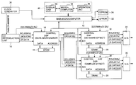
- FIG. 1 is a block diagram of an embodiment of a recording medium reproduction apparatus according to the present invention.
- FIG. 2 is a block diagram showing functions of a data maintenance DSP shown in FIG. 1;
- FIG. 3 is a block diagram showing functions of a CD sound effect DSP and a sampler effect DSP shown in FIG. 1;
- FIG. 4 is a plan view of controller units of a pair of the recording medium reproduction apparatus according to the present invention.
- FIG. 5 is a graph of an embodiment of a scratch operation
- FIG. 6 is a diagram showing a state of a DRAM for storing audio data during a scratch operation
- FIGS. 7 through 9 are flowcharts of a process of a scratch processing performed by the data maintenance DSP according to an embodiment of the present invention.
- FIG. 10 is a flowchart of a process of a scratch correction processing performed by the data maintenance DSP according to an embodiment of the present invention.
- FIG. 1 is a block diagram of an embodiment of a recording medium reproduction apparatus according to the present invention.
- a CD reproduction unit 10 rotationally drives a CD that is a recording medium at a reproduction rate twice as high as a normal reproduction rate (double rate).
- a reproduction signal reproduced at the double rate by a pickup of the CD reproduction unit 10 is supplied to a CD reproduction digital signal processor (DSP) in the CD reproduction unit 10 via a radiofrequency (RF) amplifier.
- DSP digital signal processor
- RF radiofrequency
- a signal processing such as a demodulation using eight to fourteen modulation (EFM) or a decoding using cross-interleave Reed-Solomon code (CIRC) is performed on the reproduction signal.
- EFM eight to fourteen modulation
- CIRC cross-interleave Reed-Solomon code
- a subcode is separated from the reproduction signal to be decoded.
- the subcode data is stored in a random access memory (RAM) in a main microcomputer 12 in accordance with a counter signal supplied from the main microcomputer 12 .
- Audio data subjected to the signal processing in the CD reproduction DSP is supplied to a data maintenance DSP 14 .
- a dynamic RAM (DRAM) 16 for storing the audio data is connected to the data maintenance DSP 14 , which serves as a memory controller.
- the DRAM 16 is capable of storing the audio data transmitted from the data maintenance DSP 14 for approximately ten seconds for example, and serves to realize a variety of functions, such as an anti-shock function for providing protection when a sound skip is caused by a defect in the audio data, a quick start function for instantaneously starting a desired tune, a seamless loop function for repeatedly reproducing the audio data between predetermined two points, a function for a scratch processing, a function for varying the tempo of a tune, and a brake function for gradually reducing the reproduction rate to stop the reproduction.
- functions such as an anti-shock function for providing protection when a sound skip is caused by a defect in the audio data, a quick start function for instantaneously starting a desired tune, a seamless loop function for repeatedly reproducing the audio data between predetermined two points, a function for a scratch processing, a function for varying the tempo of a tune, and a brake function for gradually reducing the reproduction rate to stop the reproduction.
- the data maintenance DSP 14 writes the audio data read at the double rate into the DRAM 16 in accordance with the counter signal supplied from the main microcomputer 12 , and simultaneously reads the audio data at a single rate (normal rate) in accordance with the counter signal supplied from the main microcomputer 12 so as to supply the audio data to a CD sound effect DSP 18 .
- a work memory DRAM 20 is connected to the CD sound effect DSP 18 , which performs a variety of effect processing, such as a key (musical interval) adjustment, an output level adjustment, and a voice reduction function to reduce only the volume of the vocal sound of a tune.
- the audio data output from the DSP 18 is supplied to a digital-to-analog (D/A) converter 22 through a digital filter, and is also supplied to a sampler effect DSP 26 .
- D/A digital-to-analog
- An audio data storage DRAM 28 is connected to the sampler effect DSP 26 , which serves as a memory controller.
- the audio data storage DRAM 28 is capable of storing the audio data for approximately ten seconds, for example.
- the sampler effect DSP 26 performs a sampler processing.
- the sampler effect DSP 26 stores the audio data picked up during a period between sampling start and end points specified by a user into the audio data storage DRAM 28 , and reads the stored audio data at a reproduction timing specified by the user to supply the stored audio data to a D/A converter 30 and to the DSP 18 .
- the DSP 18 combines the output audio data thereof with the audio data supplied from the DSP 26 to supply the combined audio data to the D/A converter 22 .
- the main microcomputer 12 is connected to an erasable and programmable read only memory (EPROM) 32 storing programs and data for processing and to an electrically erasable and programmable read only memory (EEPROM) 34 into which a variety of set values of each tune or track, such as a tempo value and a loop point, are stored.
- EPROM erasable and programmable read only memory
- EEPROM electrically erasable and programmable read only memory
- a clock generator 36 generates a clock signal and supplies the clock signal to the CD reproduction unit 10 and to the main microcomputer 12 .
- the main microcomputer 12 reads the subcode from the RAM housed therein in accordance with the counter signal to supply the subcode to a microcomputer 42 of a controller unit 40 .
- the microcomputer 42 converts the subcode into a time code and displays the time code on a display unit 44 .
- the controller unit 40 which includes an operation unit 46 including a variety of operation keys operated by the user, is connected to the microcomputer 42 .
- FIG. 2 is a block diagram showing functions of the DSP 14
- FIG. 3 is a block diagram showing functions of the DSPs 18 and 26 .
- a comparison/connection function 50 of the DSP 14 in accordance with the counter signal supplied from the main microcomputer 12 , compares audio data read at the double rate with the last data stored in the DRAM 16 , and connects the audio data to the last data stored in the DRAM 16 .
- a memory write function 51 writes the connected audio data into the DRAM 16 .
- a memory read function 52 reads audio data out of the DRAM 16 .
- a tempo function 54 varies a read rate of the memory read function 52 for a tempo adjustment.
- a fade-in/fade-out function 55 adjusts the level of audio data at a time of fade-in or fade-out.
- a de-emphasis function 60 of the DSP 18 performs a de-emphasis processing to return an emphasis level at a time of CD recording to its original level.
- a key adjustment function 61 fixes the tempo and variably adjusts the key.
- a beats per minute (BPM) function 62 counts the number of beats per minute of a tune.
- a voice reduction function 63 reduces the volume of the vocal sound of a tune.
- An output level adjustment function 64 adjusts an output level. The output level adjustment function 64 outputs the audio data through a combination function 65 , and supplies the audio data to a sampler function 67 of the DSP 26 when a switch 66 is “ON”.
- the sampler function 67 writes audio data into the DRAM 28 , and, when a switch 70 is “ON”, reads the audio data out of the DRAM 28 .
- a tempo adjustment function 68 adjusts the tempo of the audio data supplied from the sampler function 67 .
- a key adjustment function 69 fixes the tempo and variably adjusts the key. Thereafter, the key adjustment function 69 outputs the audio data through the switch 70 , and supplies the audio data to the combination function 65 through a switch 71 of the DSP 18 , which switch is switched “ON” together with the switch 70 .
- the combination function 65 combines the audio data supplied from the key adjustment function 69 with the audio data supplied from the output level adjustment function 64 to output the combined audio data.
- FIG. 4 is a plan view of the controller units 40 of a pair of the recording medium reproduction apparatus. Since the respective controller units 40 have the same structure, only one of the respective units 40 is referred to by numerals in a description thereof given below.
- a display 80 of the display unit 44 displays a variety of information such as a track number and a time code, while a display 81 of the display unit 44 displays a BPM value.
- the operation unit 46 includes a preset key 82 , a jog dial 83 , a skip key 84 , a search key 85 , a play/pause key 86 , a bank key 87 , a memory key 88 , a recall key 89 , an enter key 90 , a TAP key 91 , a BPM key 92 , a tempo SYNC key 93 , a beat SYNC key 94 , a loop key 95 , an A key 96 , a B key 97 , a sample key 98 , an IN key 99 , an OUT key 100 , a tempo key 101 , a tempo volume 102 , a scratch key 103 , a brake key 104 , a ten key 105 ,
- the scratch key 103 is first pressed to set the controller unit 40 ready for a scratch, and the jog dial 83 is rotated to perform a scratch reproduction.
- the jog dial 83 employs a rotary encoder or the like and transmits rotation detection pulses to the microcomputer 42 so that the speed, direction, and cessation of the rotation of the jog dial 83 can be recognized.
- the jog dial 83 is rotated clockwise to perform a forward reproduction, and is rotated counterclockwise to perform a reverse reproduction. The scratch reproduction can be performed even when a normal reproduction is paused or performed.
- FIG. 5 is a graph of an embodiment of a scratch operation.
- the scratch operation can be performed by pressing the scratch key 103 and then rotating the jog dial 83 clockwise and counterclockwise.
- the reproduction rate varies depending on the rotation speed of the jog dial 83 .
- the reproduction rate varies over a range of ⁇ 50% of the normal reproduction rate.
- the scratch operation is performed from a PLAY (normal reproduction) state in which the reproduction is performed at a constant rate (normal reproduction rate)
- the reproduction is set in the PLAY state after the scratch operation is over.
- Time required to set the reproduction in the PLAY state after the scratch operation is over can be changed by the preset key 82 . If the required time is set in the EEPROM 34 shown in FIG.
- a normal reproduced sound takes time in being output after the scratch operation with the set value of 0.5 second, thus preventing the succession of the scratch operation and the normal reproduction operation.
- the scratch operation is performed from a READY (pause) state in which the jog dial 83 remains stationary, the reproduction is set in the READY state after the scratch operation is over.
- the jog dial 83 is rotated clockwise at a speed of two rotations per second from the stationary state thereof to set the forward reproduction rate at a rate of +50%. Thereafter, the jog dial 83 is set at rest and then is rotated counterclockwise at a speed of 0.7 rotation per second (three-quarters rotation per second) to set the reverse reproduction rate at a rate of ⁇ 25%.
- any scratch operation can be realized by the combination of the clockwise and counterclockwise rotation and the rotational speed of the jog dial 83 .
- “+” shows a rate higher than the constant rate
- ⁇ shows a rate lower than the constant rate.
- the solid lines show the forward reproduction and the broken lines show the reverse reproduction.
- the above-described values of the rotational speed with respect to the reproduction rates are examples.
- the rotational speed with respect to the reproduction rate can be changed by the preset key 82 . If the rotational speed of the jog dial 83 with respect to the reproduction rate of +50% is set in the EEPROM 34 shown in FIG. 1 to have three values of two rotations per second, which is a default value, three rotations per second, and 1.5 rotations per second, by selecting the selection mode by the preset key 82 , the set values can be changed by the jog dial 83 to be determined by the enter key 90 . The values of the rotational speed of the jog dial 83 with respect to the minus reproduction rates are simultaneously changed at the same rate.
- the scratch operation can reproduce a higher-keyed sound over a longer reproduction length with the value of 1.5 rotations per second at the reproduction rate of +50%.
- the rotational speed of the jog dial 83 with respect to the reproduction rate can be changed by means of the jog speed setting switch 106 .
- a dial 106 A of the jog speed setting switch 106 is turned counterclockwise to be set at a position of “2” so that the rotational speed with respect to the reproduction rate can be set to have double the value set by the preset key 82 . If the dial 106 A is set at a center position of “1”, the rotational speed can be set to have the value set by the preset key 82 . If the dial 106 A is turned clockwise to be set at a position of “1 ⁇ 2”, the rotational speed can be set to have half the value set by the preset key 82 .
- the values of the rotational speed with respect to the reproduction rate can be changed gradually or continuously within a range from the above-described position “1 ⁇ 2” to the position “2” of the dial 106 A.
- the jog speed setting switch 106 allows the DJ to easily set a desired value of the rotational speed with respect to the reproduction rate, and to achieve a scratch performance with a desired key over a desired reproduction length.
- FIG. 6 is a diagram showing a state of the DRAM 16 during a scratch operation.
- the audio data is stored in positions clockwise from SA to VWA in an order reproduced in the CD reproduction unit 10 .
- a normal scratch reproduction by the scratch operation always reproduces the audio data from the CD at the double rate, and stores the reproduced audio data in the DRAM 16 .
- a maximum of 11-second-long audio data is stored over the positions SA to VWA in the DRAM 16 .
- the position SA is set as a readout reference position during a normal anti-shock reproduction.
- the 5.5-second-long first half of the audio data is stored in the DRAM 16 over a region from the reference position RA to the position VWA
- the 5.5-second-long second half of the audio data is stored in the DRAM 16 over a region from the position SA to the reference position RA.
- the first and second halves of the audio data are necessary for the forward and reverse reproductions, respectively.
- the audio data is reproduced by the scratch operation for five seconds from the reference position RA toward the position SA, and the reproduction of the audio data is ceased at a position 0.5 second short of the position SA.
- the rotation of the jog dial 83 is stopped during the above-described operation, the normal reproduction is performed in the scratch mode in the case of the scratch reproduction in the PLAY state, and the reproduction enters the READY state in the case of the scratch reproduction in the READY state.
- the audio data is reproduced by the scratch operation for five seconds from the reference position RA toward the position VWA. Thereafter, when the audio data is read out from the DRAM 16 up to a position 0.5 second short of the position VWA, the next audio data is prefetched from the CD to be stored in the DRAM 16 over a region following the position VWA.
- the rotation of the jog dial 83 is stopped during the above-described operation, the normal reproduction is performed in the scratch mode in the case of the scratch reproduction in the PLAY state, and the reproduction enters the READY state in the case of the scratch reproduction in the READY state. Further, when a reproduction position falls between two tunes (tracks) during the scratch operation, the scratch reproduction is ceased because there is a section without any signal between the two tunes (tracks).
- FIGS. 7 through 9 show a flowchart of a process of a scratch processing performed by the DSP 14 according to an embodiment of the present invention.
- step S 100 of FIG. 7 the scratch key 103 is pressed to set the scratch mode.
- step S 101 it is determined whether the reproduction is in the PLAY state. If it is determined in step S 101 that the reproduction is in the PLAY state, the process goes to step S 102 .
- step S 102 audio data read in advance into the DRAM 16 is set to be 5.5 seconds long, and, while keeping 5.5-second-long audio data already read out from the DRAM 16 and stored therein over the region from a present reproduction position (a data readout position on the DRAM 16 ), which is set to be the reference position RA, to the position SA, the 5.5-second-long audio data reproduced from the CD is kept in the DRAM 16 over the region from the reference position RA to the position VWA.
- step S 103 the rotation of the jog dial 83 is waited for, and when the jog dial 83 is rotated, the process goes to step S 104 .
- step S 104 if the reproduction is in the READY state, readout from the DRAM 16 of the DSP 14 is permitted, and if the reproduction is the scratch reproduction in the PLAY state, writing into the DRAM 16 of the DSP 14 is inhibited.
- step S 105 a rotational speed of the jog dial 83 is detected, and, in step S 106 , a reproduction rate corresponding to the rotational speed (TEMPO) is determined.
- TEMPO rotational speed
- step S 117 it is determined whether the reproduction is in the READY state. If it is determined in step S 117 that the reproduction is in the READY state, the process goes to step S 118 and steps shown in FIG. 9 are performed. On the other hand, if it is determined that the reproduction is not in the READY state, this scratch processing ends.
- step S 107 it is determined, based on the detection result of the rotation of the jog dial 83 in step S 103 , whether the jog dial 83 is rotated in a forward direction. If it is determined that the jog dial 83 is not rotated in the forward direction, that is, that the jog dial 83 is rotated in a reverse direction, the process goes to step S 108 .
- step S 108 the readout from the DRAM 16 of the DSP 14 is performed in a reverse direction toward the position SA from the present reproduction position. In performing step S 108 for the first time, the readout from the DRAM 16 is started from the reference position RA. Thereafter, in step S 109 , the scratch reproduction is performed.
- step S 110 it is determined whether the readout position proceeds in the reverse direction to a position 0.5 second short of an enabled SA position. If it is determined in step S 110 that the readout position proceeds to the position 0.5 second short of the enabled SA position, in step S 111 , the readout from the DRAM 16 is inhibited and the reproduction is ceased.
- step S 110 If it is determined in step S 110 that the readout position does not proceed to the position 0.5 second short of the position SA, in step S 116 , it is determined whether the rotation of the jog dial 83 is stopped. If it is determined that the rotation of the jog dial 83 is stopped, step S 107 and the steps thereafter shown in FIG. 7 are performed. If it is determined that the rotation is not stopped, step S 104 and the steps thereafter shown in FIG. 7 are performed.
- step S 112 the readout from the DRAM 16 of the DSP 14 is performed in a forward direction toward the position VWA from the present reproduction position.
- step S 112 for the first time the readout from the DRAM 16 is started from the reference position RA.
- step S 113 the scratch reproduction is performed.
- step S 114 it is determined whether the readout position proceeds in the forward direction to the position 0.5 second short of an enabled VWA position.
- step S 115 the readout from the DRAM 16 is continued to continue the scratch reproduction, and the next audio data is prefetched from the CD to be stored in the region following the position VWA on the DRAM 16 .
- step S 116 it is determined whether the rotation of the jog dial 83 is stopped. If it is determined that the rotation is stopped, the process returns to step S 101 shown in FIG. 7 and the steps thereafter are performed. If it is determined that the rotation is not stopped, the process returns to step S 104 shown in FIG. 7 and the steps thereafter are performed. Thus, the scratch reproduction can be performed in the PLAY state in the scratch mode through steps S 102 through S 116 .
- step S 118 it is determined whether 5.5-second-long future and past audio data are already stored in the DRAM 16 over corresponding regions extending in the respective forward and reverse directions from a reproduction position at the time of the READY state. If it is determined that both of the 5.5-second-long future and past audio data are not stored in the respective regions, in step S 120 , it is determined whether it is the future audio data stored in the forward direction that is insufficient. If it is determined that the future data is insufficient, in step S 124 , data reproduced from the CD is written into the DRAM 16 over a region extending from the last VWA position so that the data is read into the DRAM 16 in advance.
- step S 120 if it is determined in step S 120 that the future audio data stored in the forward direction is sufficient, but that the past audio data stored in the reverse direction is insufficient, in step S 121 , the DSP 14 is initialized. Then, in step S 122 , a position 5.5 seconds away in the reverse direction from the reproduction position at the time of the READY state is searched on the DRAM 16 . In step S 123 , data reproduced from the CD is written into the DRAM 16 over a region extending from the searched position so that 11-second-long data is read into the DRAM 16 in advance. Thereafter, the process returns to step S 118 and the steps thereafter are performed.
- step S 118 If it is determined in step S 118 that both of the 5.5-second-long future and past audio data are stored in the respective regions, in step S 119 , the replay of the CR is paused at the last enabled VWA position, and the writing into the DRAM 16 is inhibited. Thereafter, the process returns to step S 103 and the steps thereafter are performed.
- the rotational speed of the jog dial 83 is detected in step S 105 .
- the rotational speed of the jog dial 83 rotated by the DJ varies slightly. Therefore, there is always an error between the actual rotational speed and time in the forward direction and those in the reverse direction.
- the jog dial 83 is rotated, for example, clockwise from its initial position to start readout from the position RA on the DRAM 16 , and then, is rotated counterclockwise to be returned to the initial position, the present reproduction position often deviates from the reference position RA.
- FIG. 10 is a flowchart of a process of a scratch correction processing performed by the DSP 14 according to an embodiment of the present invention, in which embodiment the above-described disadvantage is eliminated. This processing is initiated when the scratch operation is started by the rotational operation of the jog dial 83 , and is performed in parallel with the processing shown in FIGS. 7 through 9.
- step S 201 the rotational direction of the jog dial 83 is detected, and in step S 202 , a first counter CA is reset. Then, in step S 203 , the first counter CA counts rotation detection pulses generated by the jog dial 83 .
- step S 204 it is determined whether the rotation of the jog dial 83 is stopped or reversed, or not. If it is determined that the rotation is not stopped or reversed, the process returns to step S 203 to continue counting the rotation detection pulses. If it is determined that the rotation is stopped, this processing ends. The stoppage of the rotation is determined when the rotation is stopped for longer than the time set by the preset key 82 , which time is required to set the reproduction in the PLAY state after the scratch operation is over.
- step S 204 if it is determined in step S 204 that the rotation is reversed, in step S 205 , a second counter CB is reset. Then, in step S 206 , the second counter CB counts the rotation detection pulses generated by the jog dial 83 . In step S 207 , it is determined whether the rotation of the jog dial 83 is stopped or reversed, or not. If it is determined that the rotation is not stopped or reversed, the process returns to step S 206 to continue counting the rotation detection pulses.
- step S 207 If it is determined in step S 207 that the rotation is stopped or reversed, the process goes to step S 208 , in which the reference position RA is corrected.
- step S 208 a value obtained by the second counter CB is subtracted from a value obtained by the first counter CA to obtain an error pulse number.
- the error pulse number is multiplied by a memory shift amount per pulse to obtain an address correction amount, and the reference position RA on the DRAM 16 is shifted by the address correction amount.
- the memory shift amount per pulse is a value corresponding to a set value of the rotational speed of the jog dial 83 with respect to the reproduction rate.
- the address correction amount is positive, the reference position RA is shifted in the rotational direction detected in step S 201 (for example, clockwise). If the address correction amount is negative, the reference position RA is shifted in a rotational direction reverse to the rotational direction detected in step S 201 (for example, counterclockwise).
- step S 209 it is determined whether the rotation of the jog dial 83 is stopped. If it is determined that the rotation is stopped, this processing ends. If it is determined that the rotation is not stopped, that is, that the rotation is reversed, the process returns to step S 201 and the steps thereafter are performed.
- the reference position RA is corrected so as to correspond to a rotational angle position of the jog dial 83 .
- the readout start position on the DRAM 16 is corrected, thus preventing an initial reproduced sound from deviating from a desired sound.
- the error pulse number is obtained by subtracting the value obtained by the second counter CB from the value obtained by the first counter CA so that the address correction amount is obtained.
- the address correction amount may be obtained based on a ratio of the value obtained by the first counter CA to the value obtained by the second counter CB.
- the recording medium reproduction apparatus includes a function to perform such a variation of the scratch operation.
- the selection mode is selected by the preset key 82 of the operation unit 46 , and “SCRT” is selected by the jog dial 83 .
- “NOR”, “FWD”, or “REV” is selected by the jog dial 83 .
- the normal scratch reproduction is performed so that both of the sounds reproduced in the forward and reverse directions are output in the scratch mode.
- “FWD” the variation of the scratch reproduction is performed so that only the sound reproduced in the forward direction is output in the scratch mode.
- selecting “REV” the variation of the scratch reproduction is performed so that only the sound reproduced in the reverse direction is output in the scratch mode.
- a method of muting a reproduced sound in the above-described variation of the scratch reproduction a method which stops data from being read out from the DRAM 16 during a mute period, or a method employing muting which stops an output of an audio signal during a mute period can be employed.
- a CD is used as a recording medium in the above-described embodiments, it is of course possible to use a DVD (Digital Versatile Disk), a MD (Mini Disk), a memory stick, or a flash memory as a recording medium.
- DVD Digital Versatile Disk
- MD Mini Disk
- a memory stick or a flash memory
Abstract
Description
Claims (5)
Applications Claiming Priority (4)
| Application Number | Priority Date | Filing Date | Title |
|---|---|---|---|
| JP2000050079 | 2000-02-25 | ||
| JP2000-050079 | 2000-02-25 | ||
| JP2000367736A JP3812332B2 (en) | 2000-02-25 | 2000-12-01 | Recording medium playback device |
| JP2000-367736 | 2000-12-01 |
Publications (2)
| Publication Number | Publication Date |
|---|---|
| US20010017821A1 US20010017821A1 (en) | 2001-08-30 |
| US6590840B2 true US6590840B2 (en) | 2003-07-08 |
Family
ID=26586151
Family Applications (1)
| Application Number | Title | Priority Date | Filing Date |
|---|---|---|---|
| US09/733,724 Expired - Lifetime US6590840B2 (en) | 2000-02-25 | 2000-12-08 | Recording medium reproduction apparatus |
Country Status (2)
| Country | Link |
|---|---|
| US (1) | US6590840B2 (en) |
| JP (1) | JP3812332B2 (en) |
Cited By (7)
| Publication number | Priority date | Publication date | Assignee | Title |
|---|---|---|---|---|
| US20020172107A1 (en) * | 2001-05-21 | 2002-11-21 | Pioneer Corporation | Information playback apparatus |
| US20030072223A1 (en) * | 2001-10-15 | 2003-04-17 | Pioneer Corporation | Information playback apparatus |
| US20030208292A1 (en) * | 2002-05-01 | 2003-11-06 | Han-Chih Liu | Digital audio signal player having a simulated analogue record |
| US20050063267A1 (en) * | 2003-09-24 | 2005-03-24 | Shuichi Soeta | Optical disc reproducing apparatus |
| US20050068857A1 (en) * | 2003-09-30 | 2005-03-31 | Masayuki Hori | Optical disc reproducing apparatus |
| WO2008126142A1 (en) * | 2007-03-30 | 2008-10-23 | Pioneer Corporation | Reproducing apparatus and program |
| US20110094369A1 (en) * | 2009-10-26 | 2011-04-28 | Shen-Chi Liu | Method for operating cue point on lighting ring of digital multimedia audio player |
Families Citing this family (14)
| Publication number | Priority date | Publication date | Assignee | Title |
|---|---|---|---|---|
| US6541690B1 (en) * | 2001-12-18 | 2003-04-01 | Jerry W. Segers, Jr. | Scratch effect controller |
| JP2003346469A (en) | 2002-05-28 | 2003-12-05 | Denon Ltd | Optical disk reproducing apparatus |
| JP4136539B2 (en) | 2002-08-23 | 2008-08-20 | パイオニア株式会社 | Information processing apparatus, method, program, recording medium for recording program, and playback apparatus |
| JP4226313B2 (en) | 2002-12-19 | 2009-02-18 | 株式会社ソニー・コンピュータエンタテインメント | Music sound reproducing apparatus and music sound reproducing program |
| JP4075654B2 (en) | 2003-03-25 | 2008-04-16 | ティアック株式会社 | Audio signal playback device |
| US20050052981A1 (en) * | 2003-09-09 | 2005-03-10 | Brian Shim | Record controlled sound playback device |
| JP2005108294A (en) * | 2003-09-29 | 2005-04-21 | Pioneer Electronic Corp | Signal processor |
| EP1763030A4 (en) * | 2004-05-31 | 2009-03-25 | Panasonic Corp | Audio reproduction device |
| WO2006104108A1 (en) * | 2005-03-28 | 2006-10-05 | Pioneer Corporation | Information reproducing device and method, and computer program |
| WO2007037274A1 (en) * | 2005-09-29 | 2007-04-05 | Pioneer Corporation | Information reproduction device and method, and computer program |
| US20070079315A1 (en) * | 2005-10-05 | 2007-04-05 | Gregor Mittersinker | Hybrid turntable |
| US8311656B2 (en) * | 2006-07-13 | 2012-11-13 | Inmusic Brands, Inc. | Music and audio playback system |
| US20100014399A1 (en) * | 2007-03-08 | 2010-01-21 | Pioneer Corporation | Information reproducing apparatus and method, and computer program |
| JP6155950B2 (en) * | 2013-08-12 | 2017-07-05 | カシオ計算機株式会社 | Sampling apparatus, sampling method and program |
Citations (7)
| Publication number | Priority date | Publication date | Assignee | Title |
|---|---|---|---|---|
| US5512704A (en) * | 1992-10-12 | 1996-04-30 | Yamaha Corporation | Electronic sound signal generator achieving scratch sound effect using scratch readout from waveform memory |
| JPH1186446A (en) | 1997-09-04 | 1999-03-30 | Sony Corp | Device and method for data reproduction |
| JPH1186447A (en) * | 1997-09-08 | 1999-03-30 | Sony Corp | Device and method of data reproduction |
| JPH11213520A (en) * | 1998-01-26 | 1999-08-06 | Sony Corp | Reproducing device |
| US6175632B1 (en) * | 1996-08-09 | 2001-01-16 | Elliot S. Marx | Universal beat synchronization of audio and lighting sources with interactive visual cueing |
| US6379244B1 (en) * | 1997-09-17 | 2002-04-30 | Konami Co., Ltd. | Music action game machine, performance operation instructing system for music action game and storage device readable by computer |
| US6434100B1 (en) * | 1999-11-09 | 2002-08-13 | Nippon Columbia Co., Ltd. | Optical disc reproducing apparatus |
-
2000
- 2000-12-01 JP JP2000367736A patent/JP3812332B2/en not_active Expired - Fee Related
- 2000-12-08 US US09/733,724 patent/US6590840B2/en not_active Expired - Lifetime
Patent Citations (7)
| Publication number | Priority date | Publication date | Assignee | Title |
|---|---|---|---|---|
| US5512704A (en) * | 1992-10-12 | 1996-04-30 | Yamaha Corporation | Electronic sound signal generator achieving scratch sound effect using scratch readout from waveform memory |
| US6175632B1 (en) * | 1996-08-09 | 2001-01-16 | Elliot S. Marx | Universal beat synchronization of audio and lighting sources with interactive visual cueing |
| JPH1186446A (en) | 1997-09-04 | 1999-03-30 | Sony Corp | Device and method for data reproduction |
| JPH1186447A (en) * | 1997-09-08 | 1999-03-30 | Sony Corp | Device and method of data reproduction |
| US6379244B1 (en) * | 1997-09-17 | 2002-04-30 | Konami Co., Ltd. | Music action game machine, performance operation instructing system for music action game and storage device readable by computer |
| JPH11213520A (en) * | 1998-01-26 | 1999-08-06 | Sony Corp | Reproducing device |
| US6434100B1 (en) * | 1999-11-09 | 2002-08-13 | Nippon Columbia Co., Ltd. | Optical disc reproducing apparatus |
Cited By (16)
| Publication number | Priority date | Publication date | Assignee | Title |
|---|---|---|---|---|
| US20060181968A1 (en) * | 2001-05-21 | 2006-08-17 | Pioneer Corporation | Information playback apparatus |
| US20020172107A1 (en) * | 2001-05-21 | 2002-11-21 | Pioneer Corporation | Information playback apparatus |
| US7394731B2 (en) | 2001-05-21 | 2008-07-01 | Pioneer Corporation | Information playback apparatus |
| US7042814B2 (en) * | 2001-05-21 | 2006-05-09 | Pioneer Corporation | Information playback apparatus |
| US20030072223A1 (en) * | 2001-10-15 | 2003-04-17 | Pioneer Corporation | Information playback apparatus |
| US6804179B2 (en) * | 2001-10-15 | 2004-10-12 | Pioneer Corporation | Information reproducing apparatus capable of performing quick access playback |
| US20030208292A1 (en) * | 2002-05-01 | 2003-11-06 | Han-Chih Liu | Digital audio signal player having a simulated analogue record |
| US7010371B2 (en) * | 2002-05-01 | 2006-03-07 | Hanpin Electron Co., Ltd. | Digital audio signal player having a simulated analogue record |
| US20050063267A1 (en) * | 2003-09-24 | 2005-03-24 | Shuichi Soeta | Optical disc reproducing apparatus |
| US7251204B2 (en) | 2003-09-24 | 2007-07-31 | D & M Holdings Inc. | Optical disc reproducing apparatus |
| US20050068857A1 (en) * | 2003-09-30 | 2005-03-31 | Masayuki Hori | Optical disc reproducing apparatus |
| US7489598B2 (en) | 2003-09-30 | 2009-02-10 | D&M Holdings Inc. | Optical disc reproducing apparatus |
| WO2008126142A1 (en) * | 2007-03-30 | 2008-10-23 | Pioneer Corporation | Reproducing apparatus and program |
| US20100110843A1 (en) * | 2007-03-30 | 2010-05-06 | Pioneer Corporation | Reproducing apparatus and program |
| US20110094369A1 (en) * | 2009-10-26 | 2011-04-28 | Shen-Chi Liu | Method for operating cue point on lighting ring of digital multimedia audio player |
| US7964782B2 (en) * | 2009-10-26 | 2011-06-21 | Hanpin Electron Co., Ltd. | Method for operating cue point on lighting ring of digital multimedia audio player |
Also Published As
| Publication number | Publication date |
|---|---|
| JP3812332B2 (en) | 2006-08-23 |
| JP2001312857A (en) | 2001-11-09 |
| US20010017821A1 (en) | 2001-08-30 |
Similar Documents
| Publication | Publication Date | Title |
|---|---|---|
| US6590840B2 (en) | Recording medium reproduction apparatus | |
| JP3157963B2 (en) | Optical disc playback device | |
| US6608803B2 (en) | Recording medium reproduction apparatus | |
| JP3687467B2 (en) | Recording medium playback device | |
| JP3743280B2 (en) | Recording medium playback device | |
| US20010002183A1 (en) | Reproducing device with cross-fading operation | |
| JP3591227B2 (en) | Karaoke equipment | |
| JP3402490B2 (en) | Information playback device | |
| JP3870656B2 (en) | Recording medium playback device | |
| JP2007257771A (en) | Reproducing device, reproducing method, program, and recording medium | |
| JP3368307B2 (en) | Information playback device | |
| JP2518190B2 (en) | Automatic playing device | |
| JP3812270B2 (en) | Recording medium playback device | |
| JPH042473Y2 (en) | ||
| JP2658450B2 (en) | Automatic performance device | |
| JP3559930B2 (en) | Information playback device | |
| JP3197744B2 (en) | Composite recording / playback device | |
| JPH05217292A (en) | Data reproducing device | |
| JP3486813B2 (en) | Information playback device | |
| JPS5942613A (en) | Digital audio player | |
| JPH061601B2 (en) | Playback device | |
| JPH01232594A (en) | Device for reproducing recording medium | |
| JPH03183051A (en) | Sound recording circuit | |
| JP2001243750A (en) | Recording medium reproducing device | |
| JPS62172586A (en) | Digital audio disk reproducing device |
Legal Events
| Date | Code | Title | Description |
|---|---|---|---|
| AS | Assignment |
Owner name: TEAC CORPORATION, JAPAN Free format text: ASSIGNMENT OF ASSIGNORS INTEREST;ASSIGNORS:INOUE, HIDEO;TUTIYA, SAIJI;SHIMIZU, YASUNOBU;AND OTHERS;REEL/FRAME:012022/0835 Effective date: 20001220 |
|
| FEPP | Fee payment procedure |
Free format text: PAYOR NUMBER ASSIGNED (ORIGINAL EVENT CODE: ASPN); ENTITY STATUS OF PATENT OWNER: LARGE ENTITY |
|
| STCF | Information on status: patent grant |
Free format text: PATENTED CASE |
|
| FPAY | Fee payment |
Year of fee payment: 4 |
|
| FPAY | Fee payment |
Year of fee payment: 8 |
|
| FPAY | Fee payment |
Year of fee payment: 12 |
|
| AS | Assignment |
Owner name: GIBSON BRANDS, INC., TENNESSEE Free format text: ASSIGNMENT OF ASSIGNORS INTEREST;ASSIGNOR:TEAC CORPORATION;REEL/FRAME:037246/0760 Effective date: 20141119 |
|
| AS | Assignment |
Owner name: BANK OF AMERICA, N.A., AS ADMINISTRATIVE AGENT, GE Free format text: SECURITY INTEREST;ASSIGNOR:GIBSON BRANDS, INC.;REEL/FRAME:039656/0788 Effective date: 20160803 Owner name: WELLS FARGO BANK, NATIONAL ASSOCIATION, AS COLLATE Free format text: SECURITY INTEREST;ASSIGNOR:GIBSON BRANDS, INC.;REEL/FRAME:039658/0005 Effective date: 20160803 |
|
| AS | Assignment |
Owner name: WILMINGTON TRUST, NATIONAL ASSOCIATION, AS COLLATE Free format text: ASSIGNMENT OF SECURITY INTEREST;ASSIGNOR:WELLS FARGO BANK, NATIONAL ASSOCIATION, AS COLLATERAL AGENT;REEL/FRAME:039687/0055 Effective date: 20160803 |
|
| AS | Assignment |
Owner name: BANK OF AMERICA, N.A., AS AGENT, GEORGIA Free format text: SECOND LIEN INTELLECTUAL PROPERTY SECURITY AGREEMENT;ASSIGNORS:GIBSON BRANDS, INC.;GIBSON INTERNATIONAL SALES LLC;GIBSON PRO AUDIO CORP.;AND OTHERS;REEL/FRAME:041760/0592 Effective date: 20170215 |
|
| AS | Assignment |
Owner name: CORTLAND CAPITAL MARKET SERVICES LLC, ILLINOIS Free format text: SECURITY INTEREST;ASSIGNOR:GIBSON BRANDS, INC.;REEL/FRAME:046239/0247 Effective date: 20180518 |
|
| AS | Assignment |
Owner name: WELLS FARGO BANK, NATIONAL ASSOCIATION, NEW YORK Free format text: SECURITY INTEREST;ASSIGNOR:GIBSON BRANDS, INC.;REEL/FRAME:047384/0215 Effective date: 20181101 |
|
| AS | Assignment |
Owner name: GIBSON BRANDS, INC., TENNESSEE Free format text: RELEASE BY SECURED PARTY;ASSIGNORS:CORTLAND CAPITAL MARKET SERVICES LLC;WILMINGTON TRUST, NATIONAL ASSOCIATION;BANK OF AMERICA, NA;REEL/FRAME:048841/0001 Effective date: 20181004 |
|
| AS | Assignment |
Owner name: GIBSON BRANDS, INC., TENNESSEE Free format text: RELEASE OF SECURITY INTEREST : RECORDED AT REEL/FRAME - 047384/0215;ASSIGNOR:WELLS FARGO BANK, NATIONAL ASSOCIATION;REEL/FRAME:054823/0016 Effective date: 20201221 |
|
| AS | Assignment |
Owner name: JPMORGAN CHASE BANK, N.A., AS COLLATERAL AGENT, ILLINOIS Free format text: GRANT OF SECURITY INTEREST IN PATENT RIGHTS;ASSIGNOR:GIBSON BRANDS, INC.;REEL/FRAME:054839/0217 Effective date: 20201221 |