US6587077B2 - Phased array antenna providing enhanced element controller data communication and related methods - Google Patents
Phased array antenna providing enhanced element controller data communication and related methods Download PDFInfo
- Publication number
- US6587077B2 US6587077B2 US09/991,482 US99148201A US6587077B2 US 6587077 B2 US6587077 B2 US 6587077B2 US 99148201 A US99148201 A US 99148201A US 6587077 B2 US6587077 B2 US 6587077B2
- Authority
- US
- United States
- Prior art keywords
- data
- phased array
- array antenna
- controllers
- controller
- Prior art date
- Legal status (The legal status is an assumption and is not a legal conclusion. Google has not performed a legal analysis and makes no representation as to the accuracy of the status listed.)
- Expired - Fee Related
Links
Images


Classifications
-
- H—ELECTRICITY
- H01—ELECTRIC ELEMENTS
- H01Q—ANTENNAS, i.e. RADIO AERIALS
- H01Q3/00—Arrangements for changing or varying the orientation or the shape of the directional pattern of the waves radiated from an antenna or antenna system
- H01Q3/26—Arrangements for changing or varying the orientation or the shape of the directional pattern of the waves radiated from an antenna or antenna system varying the relative phase or relative amplitude of energisation between two or more active radiating elements; varying the distribution of energy across a radiating aperture
- H01Q3/30—Arrangements for changing or varying the orientation or the shape of the directional pattern of the waves radiated from an antenna or antenna system varying the relative phase or relative amplitude of energisation between two or more active radiating elements; varying the distribution of energy across a radiating aperture varying the relative phase between the radiating elements of an array
- H01Q3/34—Arrangements for changing or varying the orientation or the shape of the directional pattern of the waves radiated from an antenna or antenna system varying the relative phase or relative amplitude of energisation between two or more active radiating elements; varying the distribution of energy across a radiating aperture varying the relative phase between the radiating elements of an array by electrical means
- H01Q3/36—Arrangements for changing or varying the orientation or the shape of the directional pattern of the waves radiated from an antenna or antenna system varying the relative phase or relative amplitude of energisation between two or more active radiating elements; varying the distribution of energy across a radiating aperture varying the relative phase between the radiating elements of an array by electrical means with variable phase-shifters
-
- H—ELECTRICITY
- H01—ELECTRIC ELEMENTS
- H01Q—ANTENNAS, i.e. RADIO AERIALS
- H01Q3/00—Arrangements for changing or varying the orientation or the shape of the directional pattern of the waves radiated from an antenna or antenna system
- H01Q3/26—Arrangements for changing or varying the orientation or the shape of the directional pattern of the waves radiated from an antenna or antenna system varying the relative phase or relative amplitude of energisation between two or more active radiating elements; varying the distribution of energy across a radiating aperture
Definitions
- the present invention relates to the field of communications, and, more particularly, to phased array antennas and related methods.
- Antenna systems are widely used in both ground based applications (e.g., cellular antennas) and airborne applications (e.g., airplane or satellite antennas).
- ground based applications e.g., cellular antennas
- airborne applications e.g., airplane or satellite antennas.
- so-called “smart” antenna systems such as adaptive or phased array antennas, combine the outputs of multiple antenna elements with signal processing capabilities to transmit and/or receive communications signals (e.g., microwave signals, RF signals, etc.).
- communications signals e.g., microwave signals, RF signals, etc.
- Such antenna systems can vary the transmission or reception pattern (i.e., “beam shaping” or “spoiling”) or direction (i.e., “beam steering”) of the communications signals in response to the signal environment to improve performance characteristics.
- a typical phased array antenna may include, for example, a central controller for processing the host commands and generating beam control commands (e.g., beam steering commands and/or beam spoiling commands) for the antenna elements based thereon.
- beam control commands e.g., beam steering commands and/or beam spoiling commands
- One or more element controllers may be used for controlling the antenna elements based upon the beam control commands.
- subarray controllers may also be connected between groups of element controllers and the central controller to aid in beam command processing and distribution, for example.
- One problem that may become particularly acute in large phased array antennas is that of efficiently distributing the beam commands from the subarray controllers to the element controllers. This is partly due to the fact that some beam commands are particular to a given element controller (e.g., initialization commands, phase commands, attenuation commands, delay commands), while others may be intended for all of the element controllers (e.g., beam spoiling commands, operating frequency commands). Thus, some degree of individual element addressing is typically required. Yet, many of these commands generally require distribution to the element controllers in as close to real time as is possible. This problem may be further complicated by the fact that other data may also need to be communicated to and from the element controllers, such as temperature compensation data or telemetry data, for example.
- other data may also need to be communicated to and from the element controllers, such as temperature compensation data or telemetry data, for example.
- One variation of this approach is to address an entire column of element controllers in a group and then sequentially address each element in the column. While this variation may provide some improvement, numerous sequential addressing commands and repeated sending of data may still be required.
- U.S. Pat. No. 5,353,031 to Rathi discloses an integrated module controller which, in one embodiment, is to have a respective data link for each of its associated antenna elements. In this embodiment, the module controller transmits data to all of its associated antenna elements in parallel. Yet, this approach simply may not be practical in large phased array antennas having numerous antenna elements, due to the wiring complexities that are likely to result.
- a still further approach uses a respective multiplexed bus connected between each subarray controller and subgroups of associated element controllers.
- the element controllers will have addressing straps, for example, so that individual element controllers within each subgroup can be controlled to receive respective data.
- An example of this type of architecture is also disclosed in the above noted patent to Rathi, where in one embodiment a subgroup of row elements or column elements share a common multiplexed data bus with each element receiving respective control addressing signals. While this approach also has certain advantages, it may require high bus data rates, and it may also be cumbersome to implement address straps for large numbers of elements controllers.
- phased array antenna including a substrate and a plurality of phased array antenna elements carried by the substrate, and a plurality of element controllers connected to the phased array antenna elements.
- Each element controller may be switchable between inactive and active data receiving states.
- the phased array antenna may further include a plurality of subarray controllers and a plurality of data buses. Each data bus may connect a respective subarray controller to respective columns and rows of element controllers. Further, each subarray controller may cooperate with a respective data bus for sending data in parallel to a plurality of rows of element controllers and while sequentially switching a given column of element controllers from the inactive data receiving state to the active data receiving state. Accordingly, the phased array antenna according to the present invention provides enhanced element controller data communication while reducing the need for relatively high speed busses and complex addressing protocols, which may otherwise result in increased logic complexity, power consumption, and cost.
- each subarray controller may send data in parallel to all of the rows of element controllers and while sequentially switching a given column of element controllers from the inactive data receiving state to the active data receiving state.
- Each subarray controller may further switch a plurality of columns of element controllers (e.g., all of the columns of element controllers) to the active data receiving state to send common data thereto.
- the common data may include at least one of beam shape data, temperature compensation data (e.g., temperature compensation index data), and operating frequency data.
- Each subarray controller may provide clock signals to switch the columns of element controllers between inactive and active data receiving states.
- the clock signals may be offset in time from one another to sequentially switch the columns.
- respective clock signals may be substantially the same to activate a plurality of columns.
- the data may include beam steering data, for example, and the plurality of element controllers may be a respective element controller connected to each of the phased array antenna elements.
- the phased array antenna may also include a central controller connected to the plurality of subarray controllers.
- each subarray controller may send a telemetry request command to at least one column of element controllers, and each element controller in the at least one column may respond to the telemetry request command by sending requested telemetry data.
- a method aspect of the invention is for sending data between a subarray controller and a plurality of element controllers in a phased array antenna.
- Each element controller may be switchable between inactive and active data receiving states.
- the method may include sending the data in parallel from the subarray controller to a plurality of rows of the element controllers, and sequentially switching a given column of the element controllers from the inactive data receiving state to the active data receiving state while sending the data in parallel.
- FIG. 1 is a schematic block diagram of a phased array antenna of the present invention.
- FIG. 2 is a more detailed schematic block diagram of a subarray controller and associated element controllers of the phased array antenna of FIG. 1 .
- FIG. 3 is a timing diagram illustrating sequential element controller column switching according to the present invention.
- FIG. 4 is a more detailed timing diagram illustrating sequential and simultaneous element controller column switching according to the present invention.
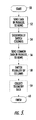
- FIG. 5 is a flow diagram illustrating a method according to the present invention.
- a phased array antenna 10 illustratively includes a substrate 11 and a plurality of phased array antenna elements 12 carried by the substrate.
- substrate refers to any surface, mechanized structure, etc., which is suitable for carrying a phased array antenna element, as will be appreciated by those of skill in the art.
- element controllers 20 FIG. 2 are connected to the phased array antenna elements 12 .
- groups of element controllers 13 a - 13 n are connected to (or integrated with) respective groups of antenna elements 14 a - 14 n. More particularly, the groups of element controllers 13 a - 13 n may include a respective element controller 20 for each antenna element 12 in a respective group of antenna elements 14 a - 14 n. Of course, those of skill in the art will appreciate that a single element controller 20 may be used to control one or more antenna elements 12 . It will also be appreciated that the element controllers 13 a - 13 n may be integrated together with the various RF components for respective antenna elements 12 in an integrated MMIC module, for example.
- the phased array antenna 10 also illustratively includes a respective subarray controller 15 a - 15 n for each group of element controllers 13 a - 13 n . Additionally, a plurality of data buses 16 a - 16 n (shown with dashed lines in FIGS. 1 and 2) connect each subarray controller 15 a - 15 n to respective columns and rows of element controllers 20 . As illustrated in FIG. 2, for example, the group of element controllers 13 a includes three columns of element controllers 20 a , 20 d , 20 g (Column 1); 20 b , 20 e , 20 h (Column 2); and 20 c , 20 f , 20 i (Column 3).
- the group of element controllers 13 a also includes three rows of element controllers 20 a - 20 c (Row 1), 20 d - 20 f (Row 2), and 20 g - 20 i (Row 3).
- the group of element controllers 13 a illustratively includes nine element controllers 20 a - 20 i, but any number of element controllers may be used in accordance with the present invention.
- the phased array antenna 10 also illustratively includes a central controller 17 connected to each of the subarray controllers 15 a - 15 n.
- the central controller 17 may receive host commands from a host system (not shown), for example, for controlling beam steering or shaping, operating frequency, temperature compensation, etc.
- the central controller 17 distributes the host commands to the subarray controllers 15 a - 15 n.
- the central controller 17 may also perform some degree of processing on the host commands, such as performing the requisite trigonometric processing to convert angles specified in the host commands into phase gradient data.
- the central controller 17 may process the host commands and provide common beam control commands (e.g., including common phase gradient data) for all of the subarray controllers 15 a - 15 n.
- the subarray controllers 15 a - 15 n may then calculate basic (i.e., uncompensated) phase settings for each antenna element 12 , and the element controllers 20 may then perform the requisite compensation (e.g., temperature compensation, etc.) for its respective antenna element 12 .
- the subarray controllers 15 a - 15 n could essentially pass the common beam control commands (e.g., including common phase gradient data) to the element controllers 20 to perform their own phase setting calculations.
- the central controller 17 could perform even further processing and provide the individual uncompensated (or even compensated) phase settings for each antenna element 12 , for example, if desired.
- subarray controller 15 may be used to perform such functions and thus serves as a central controller. This may be the case in a relatively small phased array antenna (i.e., having relatively few antenna elements 12 ), for example. Therefore, as used herein, the term “subarray controller” will be understood as either a high level controller connected between a host system and groups of elements controllers 13 a - 13 n, or a mid-level controller connected between the central controller 17 and groups of elements controllers 13 a - 13 n as illustrated in FIG. 1 .
- Each element controller 20 is preferably switchable between inactive and active data receiving states.
- each subarray controller 15 a - 15 n may advantageously cooperate with a respective data bus 16 a - 16 n for sending data in parallel to a plurality of rows of element controllers 20 and while sequentially switching a given column of element controllers from the inactive data receiving state to the active data receiving state.
- each of the data buses 16 a - 16 n may include a group of serial communication links through parallel buses may also be used.
- the clock signals CLK 1 , CLK 2 , CLK 3 are respectively provided to Columns 1, 2, and 3. Additionally, row data input/outputs Row 1 Data, Row 2 Data, and Row 3 Data are for respectively sending/receiving data to/from Row 1, Row 2, and Row 3.
- individual data for element controllers 20 a , 20 d , 20 g are respectively being presented to all of the element controllers in Row 1, Row 2, and Row 3.
- the element controllers 20 a , 20 d , and 20 g of Column 1 are switched to the active data receiving state.
- the element controllers 20 a , 20 d , and 20 g are the only element controllers that will receive or “clock in” the data from the respective data outputs Row 1 Data, Row 2 Data, and Row 3 Data.
- individual data may be clocked into (and from) each of the element controllers 20 a - 20 i more quickly than in prior art approaches and without the need for potentially cumbersome address straps.
- slower speeds may be used for the data buses 16 a - 16 n.
- the clock signals CLK 1 -CLK 3 used to switch the columns of element controllers 20 between the inactive and active data receiving states are generally less cumbersome to generate and transmit to individual element controllers.
- the subarray controller 13 a may further switch a plurality of the columns Column 1 to Column 3 to the active data receiving state to send common data thereto.
- the clock signals CLK 1 -CLK 3 are active, thus causing all of the columns Column 1 to Column 3 to be in the active data receiving state.
- common data to be used by all of the element controllers 20 a - 20 i is provided on the data outputs Row 1 Data, Row 2 Data, Row 3 Data (i.e., the same data is provided on each of these outputs).
- this common data may include a common message header to proceed a particular sequence of beam steering data, for example. This avoids the increased overhead associated with various of the above noted prior art methods resulting from the need for separate message headers.
- other common data such as beam shape data (e.g., common coefficient or index number), temperature compensation data (e.g., temperature compensation index data), and operating frequency data (e.g., normalized operating frequency index data) may also be sent.
- Sequential switching of the columns Column 1 to Column 3 provides individual beam steering data, for example, to respective element controllers 20 a - 20 i may then occur from at the times t 3 , t 4 , and t 5 (plus additional cycles, if needed) until a time t 5 .
- This sequential switching period is similar to that described above with respect to FIG. 3 and will therefore not be described again for clarity of explanation.
- the subarray controller 13 a may also advantageously send or receive other “non-real time” data at a time t 6 (plus additional cycles, if needed)
- the subarray controller 13 a may send a telemetry request command to one or more of the columns Column 1 to Column 3.
- the first bit of a telemetry request command is being sent only to Column 1, since only the clock signal CLK 1 is active.
- each element controller 20 a , 20 d , 20 g in Column 1 may respond to the telemetry request command by sending requested telemetry data.
- additional telemetry commands may subsequently be sent to the other columns, and other common data may be sent during this interval as well.
- all of the clock signals CLK 1 -CLK 3 may again become active for one or more cycles to send common data, such as an end of message indication to indicate that a particular data sequence has been completed.
- common data such as an end of message indication to indicate that a particular data sequence has been completed.
- the particular intervals during which individual or common data are sent in the above example may be varied in their placement or duration, as will be appreciated by those of skill in the art. As such, numerous other combinations are possible other than that illustrated in the exemplary illustrations of FIGS. 3 and 4 and described herein.
- the above described operation of the subarray controller 15 a and its associated element controllers 20 a - 20 i is representative of operation of the remaining subarray controllers and their respective element controllers.
- Still further bandwidth efficiency may be achieved according to the present invention by using a “zero insert” serial data encoding protocol, for example, for sending commands and data via the bus 16 a .
- beam commands and data are sent as standard non-return-to-zero (NRZ) data, with the exception that a zero is inserted when a predetermined number of logic 1's (e.g., five) are sent in a row.
- NRZ non-return-to-zero
- a data message of eight logic 1's (11111111) is encoded as 111110111.
- encoded messages with more than five logic 1's in a row may be assigned a particular meaning, such as 011111110 as a “start of message” or 11111111 as a reset command for the element controllers 20 a - 20 i.
- the above zero insert encoding protocol reduces bandwidth requirements and simplifies the detection of message headers.
- other suitable encoding protocols such as 8B/10B, Manchester encoding, etc. may also be used in accordance with the present invention.
- Each element controller 20 a - 20 i is preferably switchable between inactive and active data receiving states, as noted above.
- the method may begin (Block 50 ) with sending the data in parallel from the subarray controller 13 a to a plurality of the rows Row 1-Row 3 of element controllers 20 a - 20 i, at Block 52 .
- the method may further include sequentially switching a given column of the element controllers 20 a - 20 i from the inactive data receiving state to the active data receiving state while sending the data (Block 54 ), as described above.
- common data may optionally be sent to rows Row 1-Row 3 (Block 56 ), and a plurality of the columns Column 1-Column 3 may be switched to the active data receiving state (Block 58 ).
- telemetry data may optionally be collected as described above (Block 59 ), and the method concludes at Block 60 . Additional aspects of the method will be understood by those of skill in the art based upon the foregoing description.
Abstract
A phased array antenna may include a substrate and a plurality of phased array antenna elements carried by the substrate, and a plurality of element controllers connected to the phased array antenna elements. Each element controller may be switchable between inactive and active data receiving states. The phased array antenna may further include a plurality of subarray controllers and a plurality of data buses. Each data bus may connect a respective subarray controller to respective columns and rows of element controllers. Further, each subarray controller may cooperate with a respective data bus for sending data in parallel to a plurality of rows of element controllers and while sequentially switching a given column of element controllers from the inactive data receiving state to the active data receiving state
Description
This application is based upon prior filed copending provisional application Ser. No. 60/255,007 filed Dec. 12, 2000, now abandoned the entire subject matter of which is incorporated herein by reference in its entirety.
The present invention relates to the field of communications, and, more particularly, to phased array antennas and related methods.
Antenna systems are widely used in both ground based applications (e.g., cellular antennas) and airborne applications (e.g., airplane or satellite antennas). For example, so-called “smart” antenna systems, such as adaptive or phased array antennas, combine the outputs of multiple antenna elements with signal processing capabilities to transmit and/or receive communications signals (e.g., microwave signals, RF signals, etc.). As a result, such antenna systems can vary the transmission or reception pattern (i.e., “beam shaping” or “spoiling”) or direction (i.e., “beam steering”) of the communications signals in response to the signal environment to improve performance characteristics.
A typical phased array antenna may include, for example, a central controller for processing the host commands and generating beam control commands (e.g., beam steering commands and/or beam spoiling commands) for the antenna elements based thereon. One or more element controllers may be used for controlling the antenna elements based upon the beam control commands. In larger phased array antennas, subarray controllers may also be connected between groups of element controllers and the central controller to aid in beam command processing and distribution, for example.
One problem that may become particularly acute in large phased array antennas is that of efficiently distributing the beam commands from the subarray controllers to the element controllers. This is partly due to the fact that some beam commands are particular to a given element controller (e.g., initialization commands, phase commands, attenuation commands, delay commands), while others may be intended for all of the element controllers (e.g., beam spoiling commands, operating frequency commands). Thus, some degree of individual element addressing is typically required. Yet, many of these commands generally require distribution to the element controllers in as close to real time as is possible. This problem may be further complicated by the fact that other data may also need to be communicated to and from the element controllers, such as temperature compensation data or telemetry data, for example.
Several prior art approaches exist for sending and receiving data to and from element controllers. For example, one such approach is to arrange the group of element controllers associated with each subarray controller into rows and columns, and individually address each of the element controllers to send data thereto. A disadvantage of this approach is that numerous sequential addressing commands must be used, for example, to sequentially address each of the element controllers in a group. Further, common data such as headers, etc., to be sent to all of the element controllers must be repeatedly sent to each of the element controllers, adding further delays.
One variation of this approach is to address an entire column of element controllers in a group and then sequentially address each element in the column. While this variation may provide some improvement, numerous sequential addressing commands and repeated sending of data may still be required.
Another prior art approach is to provide a dedicated data link from each subarray controller to each of its associated element controllers. By way of example, U.S. Pat. No. 5,353,031 to Rathi discloses an integrated module controller which, in one embodiment, is to have a respective data link for each of its associated antenna elements. In this embodiment, the module controller transmits data to all of its associated antenna elements in parallel. Yet, this approach simply may not be practical in large phased array antennas having numerous antenna elements, due to the wiring complexities that are likely to result.
A still further approach uses a respective multiplexed bus connected between each subarray controller and subgroups of associated element controllers. In such an approach, the element controllers will have addressing straps, for example, so that individual element controllers within each subgroup can be controlled to receive respective data. An example of this type of architecture is also disclosed in the above noted patent to Rathi, where in one embodiment a subgroup of row elements or column elements share a common multiplexed data bus with each element receiving respective control addressing signals. While this approach also has certain advantages, it may require high bus data rates, and it may also be cumbersome to implement address straps for large numbers of elements controllers.
In view of the foregoing background, it is therefore an object of the present invention to provide a phased array antenna with enhanced element controller data communication and related methods.
This and other objects, features, and advantages in accordance with the present invention are provided by a phased array antenna including a substrate and a plurality of phased array antenna elements carried by the substrate, and a plurality of element controllers connected to the phased array antenna elements. Each element controller may be switchable between inactive and active data receiving states. The phased array antenna may further include a plurality of subarray controllers and a plurality of data buses. Each data bus may connect a respective subarray controller to respective columns and rows of element controllers. Further, each subarray controller may cooperate with a respective data bus for sending data in parallel to a plurality of rows of element controllers and while sequentially switching a given column of element controllers from the inactive data receiving state to the active data receiving state. Accordingly, the phased array antenna according to the present invention provides enhanced element controller data communication while reducing the need for relatively high speed busses and complex addressing protocols, which may otherwise result in increased logic complexity, power consumption, and cost.
More particularly, each subarray controller may send data in parallel to all of the rows of element controllers and while sequentially switching a given column of element controllers from the inactive data receiving state to the active data receiving state. Each subarray controller may further switch a plurality of columns of element controllers (e.g., all of the columns of element controllers) to the active data receiving state to send common data thereto. By way of example, the common data may include at least one of beam shape data, temperature compensation data (e.g., temperature compensation index data), and operating frequency data.
Each subarray controller may provide clock signals to switch the columns of element controllers between inactive and active data receiving states. For example, the clock signals may be offset in time from one another to sequentially switch the columns. Also, respective clock signals may be substantially the same to activate a plurality of columns. A significant advantage of this method is that the common data and the individual data for each column can be efficiently intermixed on the same bus, using a common message header. Because a column of element controllers in the inactive data receiving state has no clock, it does not “see” the data being multiplexed, and this allows for a relatively simple design of the element controller receiver logic.
The data may include beam steering data, for example, and the plurality of element controllers may be a respective element controller connected to each of the phased array antenna elements. Furthermore, the phased array antenna may also include a central controller connected to the plurality of subarray controllers. Additionally, each subarray controller may send a telemetry request command to at least one column of element controllers, and each element controller in the at least one column may respond to the telemetry request command by sending requested telemetry data. A method aspect of the invention is for sending data between a subarray controller and a plurality of element controllers in a phased array antenna. Each element controller may be switchable between inactive and active data receiving states. The method may include sending the data in parallel from the subarray controller to a plurality of rows of the element controllers, and sequentially switching a given column of the element controllers from the inactive data receiving state to the active data receiving state while sending the data in parallel.
FIG. 1 is a schematic block diagram of a phased array antenna of the present invention.
FIG. 2 is a more detailed schematic block diagram of a subarray controller and associated element controllers of the phased array antenna of FIG. 1.
FIG. 3 is a timing diagram illustrating sequential element controller column switching according to the present invention.
FIG. 4 is a more detailed timing diagram illustrating sequential and simultaneous element controller column switching according to the present invention.
FIG. 5 is a flow diagram illustrating a method according to the present invention.
The present invention will now be described more fully hereinafter with reference to the accompanying drawings, in which preferred embodiments of the invention are shown. This invention may, however, be embodied in many different forms and should not be construed as limited to the embodiments set forth herein. Rather, these embodiments are provided so that this disclosure will be thorough and complete, and will fully convey the scope of the invention to those skilled in the art. Like numbers refer to like elements throughout.
Referring initially to FIGS. 1 and 2, a phased array antenna 10 according to the present invention illustratively includes a substrate 11 and a plurality of phased array antenna elements 12 carried by the substrate. As used herein, “substrate” refers to any surface, mechanized structure, etc., which is suitable for carrying a phased array antenna element, as will be appreciated by those of skill in the art. Furthermore, a plurality of element controllers 20 (FIG. 2) are connected to the phased array antenna elements 12.
As illustrated in FIG. 1, groups of element controllers 13 a-13 n are connected to (or integrated with) respective groups of antenna elements 14 a-14 n. More particularly, the groups of element controllers 13 a-13 n may include a respective element controller 20 for each antenna element 12 in a respective group of antenna elements 14 a-14 n. Of course, those of skill in the art will appreciate that a single element controller 20 may be used to control one or more antenna elements 12. It will also be appreciated that the element controllers 13 a-13 n may be integrated together with the various RF components for respective antenna elements 12 in an integrated MMIC module, for example.
The phased array antenna 10 also illustratively includes a respective subarray controller 15 a-15 n for each group of element controllers 13 a-13 n. Additionally, a plurality of data buses 16 a-16 n (shown with dashed lines in FIGS. 1 and 2) connect each subarray controller 15 a-15 n to respective columns and rows of element controllers 20. As illustrated in FIG. 2, for example, the group of element controllers 13 a includes three columns of element controllers 20 a, 20 d, 20 g (Column 1); 20 b, 20 e, 20 h (Column 2); and 20 c, 20 f, 20 i (Column 3). The group of element controllers 13 a also includes three rows of element controllers 20 a-20 c (Row 1), 20 d-20 f (Row 2), and 20 g-20 i (Row 3). Thus, the group of element controllers 13 a illustratively includes nine element controllers 20 a-20 i, but any number of element controllers may be used in accordance with the present invention.
The phased array antenna 10 also illustratively includes a central controller 17 connected to each of the subarray controllers 15 a-15 n. The central controller 17 may receive host commands from a host system (not shown), for example, for controlling beam steering or shaping, operating frequency, temperature compensation, etc. The central controller 17 distributes the host commands to the subarray controllers 15 a-15 n.
In some embodiments, the central controller 17 may also perform some degree of processing on the host commands, such as performing the requisite trigonometric processing to convert angles specified in the host commands into phase gradient data. For example, the central controller 17 may process the host commands and provide common beam control commands (e.g., including common phase gradient data) for all of the subarray controllers 15 a-15 n.
In such embodiments, the subarray controllers 15 a-15 n may then calculate basic (i.e., uncompensated) phase settings for each antenna element 12, and the element controllers 20 may then perform the requisite compensation (e.g., temperature compensation, etc.) for its respective antenna element 12. Alternately, the subarray controllers 15 a-15 n could essentially pass the common beam control commands (e.g., including common phase gradient data) to the element controllers 20 to perform their own phase setting calculations. Of course, those of skill in the art will appreciate that the central controller 17 could perform even further processing and provide the individual uncompensated (or even compensated) phase settings for each antenna element 12, for example, if desired.
It will also be appreciated by those of skill in the art that in some embodiments of the present invention a single subarray controller 15 may be used to perform such functions and thus serves as a central controller. This may be the case in a relatively small phased array antenna (i.e., having relatively few antenna elements 12), for example. Therefore, as used herein, the term “subarray controller” will be understood as either a high level controller connected between a host system and groups of elements controllers 13 a-13 n, or a mid-level controller connected between the central controller 17 and groups of elements controllers 13 a-13 n as illustrated in FIG. 1.
Each element controller 20 is preferably switchable between inactive and active data receiving states. According to the present invention, each subarray controller 15 a-15 n may advantageously cooperate with a respective data bus 16 a-16 n for sending data in parallel to a plurality of rows of element controllers 20 and while sequentially switching a given column of element controllers from the inactive data receiving state to the active data receiving state. To this end, each of the data buses 16 a-16 n may include a group of serial communication links through parallel buses may also be used.
The foregoing will be more clearly understood with reference to the timing diagram of FIG. 3. As illustrated in FIG. 2, the clock signals CLK1, CLK2, CLK3 are respectively provided to Columns 1, 2, and 3. Additionally, row data input/outputs Row 1 Data, Row 2 Data, and Row 3 Data are for respectively sending/receiving data to/from Row 1, Row 2, and Row 3. In the example illustrated in FIG. 3, at a time t1, individual data for element controllers 20 a, 20 d, 20 g are respectively being presented to all of the element controllers in Row 1, Row 2, and Row 3. Yet, since only the clock signal CLK1 is active during this time (i.e., the clock signals CLK1-CLK3 are offset from one another), only the element controllers 20 a, 20 d, and 20 g of Column 1 are switched to the active data receiving state. As such, the element controllers 20 a, 20 d, and 20 g are the only element controllers that will receive or “clock in” the data from the respective data outputs Row 1 Data, Row 2 Data, and Row 3 Data.
Likewise, at a time t2, only the clock signal CLK2 is active. Thus, only the element controllers 20 b, 20 e, 20 h of Column 2 will be switched to the active data receiving state and therefore clock in the data from the respective data outputs Row 1 Data, Row 2 Data, and Row 3 Data. Again, at the time t2, the data output by the subarray controller 15 a on the data outputs Row 1 Data, Row 2 Data, and Row 3 Data are individual data intended only for the element controllers 20 b, 20 e, 20 h. In the same way, individual data is clocked in only by the element controllers 20 c, 20 f, 20 i of Column 3 at a time t3. It should be noted that although positive edge-triggered logic has illustratively been shown as an active clock signal, negative edge-triggered logic or level-triggered (i.e., write strobe) logic could also be used, as will be understood by those skilled in the art.
Accordingly, individual data may be clocked into (and from) each of the element controllers 20 a-20 i more quickly than in prior art approaches and without the need for potentially cumbersome address straps. Further, because of the enhanced utilization of data bus bandwidth, slower speeds may be used for the data buses 16 a-16 n. In addition, the clock signals CLK1-CLK3 used to switch the columns of element controllers 20 between the inactive and active data receiving states are generally less cumbersome to generate and transmit to individual element controllers. Thus, it will be appreciated by those of skill in the art that the present invention provides enhanced element controller data communication without the associated increases in logic complexity, power consumption, and cost that may accompany one or more of the above described prior art approaches.
Turning now additionally to FIG. 4, the subarray controller 13 a may further switch a plurality of the columns Column 1 to Column 3 to the active data receiving state to send common data thereto. In the illustrated example, it may seen that at the times t1 and t2 all of the clock signals CLK1-CLK3 are active, thus causing all of the columns Column 1 to Column 3 to be in the active data receiving state. At the same time, common data to be used by all of the element controllers 20 a-20 i is provided on the data outputs Row 1 Data, Row 2 Data, Row 3 Data (i.e., the same data is provided on each of these outputs).
More particularly, at the times t1 and t2, this common data may include a common message header to proceed a particular sequence of beam steering data, for example. This avoids the increased overhead associated with various of the above noted prior art methods resulting from the need for separate message headers. Furthermore, at the time t2 (plus similar additional cycles, if needed) other common data such as beam shape data (e.g., common coefficient or index number), temperature compensation data (e.g., temperature compensation index data), and operating frequency data (e.g., normalized operating frequency index data) may also be sent.
Sequential switching of the columns Column 1 to Column 3 provides individual beam steering data, for example, to respective element controllers 20 a-20 i may then occur from at the times t3, t4, and t5 (plus additional cycles, if needed) until a time t5. This sequential switching period is similar to that described above with respect to FIG. 3 and will therefore not be described again for clarity of explanation.
Additionally, the subarray controller 13 a may also advantageously send or receive other “non-real time” data at a time t6 (plus additional cycles, if needed) For example, the subarray controller 13 a may send a telemetry request command to one or more of the columns Column 1 to Column 3. In the illustrated example, the first bit of a telemetry request command is being sent only to Column 1, since only the clock signal CLK1 is active. Upon receiving the bits of this command, each element controller 20 a, 20 d, 20 g in Column 1 may respond to the telemetry request command by sending requested telemetry data. Of course, additional telemetry commands may subsequently be sent to the other columns, and other common data may be sent during this interval as well. Those of skill in the art will appreciate that by efficiently combining both real and non-real time bus traffic in such a manner, telemetry data is collected in a relatively convenient fashion which simplifies the task of performing “health checks” by higher level controllers (e.g., the central controller 17).
Further, at a time t7 all of the clock signals CLK1-CLK3 may again become active for one or more cycles to send common data, such as an end of message indication to indicate that a particular data sequence has been completed. It should be noted that the particular intervals during which individual or common data are sent in the above example may be varied in their placement or duration, as will be appreciated by those of skill in the art. As such, numerous other combinations are possible other than that illustrated in the exemplary illustrations of FIGS. 3 and 4 and described herein. It should also be noted that the above described operation of the subarray controller 15 a and its associated element controllers 20 a-20 i is representative of operation of the remaining subarray controllers and their respective element controllers.
Still further bandwidth efficiency may be achieved according to the present invention by using a “zero insert” serial data encoding protocol, for example, for sending commands and data via the bus 16 a. Using this protocol, beam commands and data are sent as standard non-return-to-zero (NRZ) data, with the exception that a zero is inserted when a predetermined number of logic 1's (e.g., five) are sent in a row. By way of example, a data message of eight logic 1's (11111111) is encoded as 111110111. Additionally, encoded messages with more than five logic 1's in a row may be assigned a particular meaning, such as 011111110 as a “start of message” or 11111111 as a reset command for the element controllers 20 a-20 i.
As will be appreciated by those of skill in the art, the above zero insert encoding protocol reduces bandwidth requirements and simplifies the detection of message headers. Of course, other suitable encoding protocols such as 8B/10B, Manchester encoding, etc. may also be used in accordance with the present invention.
Referring now to the flow diagram illustrated in FIG. 5, a method for sending data between a subarray controller 13 a and a plurality of element controllers 20 a-20 n in a phased array antenna 10 will now be described. Each element controller 20 a-20 i is preferably switchable between inactive and active data receiving states, as noted above. The method may begin (Block 50) with sending the data in parallel from the subarray controller 13 a to a plurality of the rows Row 1-Row 3 of element controllers 20 a-20 i, at Block 52.
The method may further include sequentially switching a given column of the element controllers 20 a-20 i from the inactive data receiving state to the active data receiving state while sending the data (Block 54), as described above. Again, common data may optionally be sent to rows Row 1-Row 3 (Block 56), and a plurality of the columns Column 1-Column 3 may be switched to the active data receiving state (Block 58). Of course, telemetry data may optionally be collected as described above (Block 59), and the method concludes at Block 60. Additional aspects of the method will be understood by those of skill in the art based upon the foregoing description.
Many modifications and other embodiments of the invention will come to the mind of one skilled in the art having the benefit of the teachings presented in the foregoing descriptions and the associated drawings. Therefore, it is understood that the invention is not to be limited to the specific embodiments disclosed, and that modifications and embodiments are intended to be included within the scope of the appended claims.
Claims (38)
1. A phased array antenna comprising:
a substrate and a plurality of phased array antenna elements carried by said substrate;
a plurality of element controllers connected to said phased array antenna elements, each element controller switchable between inactive and active data receiving states;
a plurality of subarray controllers; and
a plurality of data buses, each data bus connecting a respective subarray controller to respective columns and rows of element controllers;
each subarray controller cooperating with a respective data bus for sending data in parallel to a plurality of rows of element controllers and while sequentially switching a given column of element controllers from the inactive data receiving state to the active data receiving state.
2. The phased array antenna according to claim 1 wherein each subarray controller sends data in parallel to all of the rows of element controllers and while sequentially switching a given column of element controllers from the inactive data receiving state to the active data receiving state.
3. The phased array antenna according to claim 1 wherein each subarray controller further switches a plurality of columns of element controllers to the active data receiving state to send common data thereto.
4. The phased array antenna according to claim 3 wherein the common data comprises at least one of beam shape data, temperature compensation data, and operating frequency data.
5. The phased array antenna according to claim 1 wherein each subarray controller further switches all columns of element controllers to the active data receiving state to send common data thereto.
6. The phased array antenna according to claim 1 wherein each subarray controller provides clock signals to switch the columns of element controllers between inactive and active data receiving states.
7. The phased array antenna according to claim 6 wherein the clock signals are offset in time from one another to sequentially switch the columns.
8. The phased array antenna according to claim 6 wherein respective clock signals are substantially the same to activate a plurality of columns.
9. The phased array antenna according to claim 1 wherein each subarray controller sends a telemetry request command to at least one column of element controllers; and wherein each element controller in said at least one column responds to the telemetry request command by sending requested telemetry data.
10. The phased array antenna according to claim 1 wherein the data comprises beam steering data.
11. The phased array antenna according to claim 1 wherein said plurality of element controllers comprises a respective element controller connected to each of said phased array antenna elements.
12. The phased array antenna according to claim 1 further comprising a central controller connected to said plurality of subarray controllers.
13. A phased array antenna comprising:
a substrate and a plurality of phased array antenna elements carried by said substrate;
a respective element controller connected to each of said phased array antenna elements, each element controller switchable between inactive and active data receiving states;
a plurality of subarray controllers; and
a plurality of data buses, each data bus connecting a respective subarray controller to respective columns and rows of element controllers;
each subarray controller cooperating with a respective data bus for sending data in parallel to all of the rows of element controllers and while sequentially switching a given column of element controllers from the inactive data receiving state to the active data receiving state.
14. The phased array antenna according to claim 13 wherein each subarray controller further switches a plurality of columns of element controllers to the active data receiving state to send common data thereto.
15. The phased array antenna according to claim 14 wherein the common data comprises at least one of beam shape data, temperature compensation data, and operating frequency data.
16. The phased array antenna according to claim 13 wherein each subarray controller further switches all columns of element controllers to the active data receiving state to send common data thereto.
17. The phased array antenna according to claim 13 wherein each subarray controller provides clock signals to switch the columns of element controllers between inactive and active data receiving states.
18. The phased array antenna according to claim 17 wherein the clock signals are offset in time from one another to sequentially switch the columns.
19. The phased array antenna according to claim 17 wherein respective clock signals are substantially the same to activate a plurality of columns.
20. The phased array antenna according to claim 13 wherein each subarray controller sends a telemetry request command to at least one column of element controllers; and wherein each element controller in said at least one column responds to the telemetry request command by sending requested telemetry data.
21. The phased array antenna according to claim 13 wherein the data comprises beam steering data.
22. The phased array antenna according to claim 13 further comprising a central controller connected to said plurality of subarray controllers.
23. A phased array antenna comprising:
a substrate and a plurality of phased array antenna elements carried by said substrate;
a respective element controller connected to each of said phased array antenna elements, each element controller switchable between inactive and active data receiving states;
a plurality of subarray controllers; and
a plurality of data buses, each data bus connecting a respective subarray controller to respective columns and rows of element controllers;
each subarray controller cooperating with a respective data bus for sending data in parallel to a plurality of rows of element controllers and while also sending clock signals offset in time from one another for sequentially switching a given column of element controllers from the inactive data receiving state to the active data receiving state.
24. The phased array antenna according to claim 23 wherein each subarray controller sends data in parallel to all of the rows of element controllers and while sequentially switching a given column of element controllers from the inactive data receiving state to the active data receiving state.
25. The phased array antenna according to claim 23 wherein each subarray controller further switches a plurality of columns of element controllers to the active data receiving state to send common data thereto.
26. The phased array antenna according to claim 25 wherein the common data comprises at least one of beam shape data, temperature compensation data, and operating frequency data.
27. The phased array antenna according to claim 23 wherein each subarray controller further switches all columns of element controllers to the active data receiving state to send common data thereto.
28. The phased array antenna according to claim 23 wherein each subarray controller provides clock signals to switch the columns of element controllers between inactive and active data receiving states.
29. The phased array antenna according to claim 23 wherein each subarray controller sends a telemetry request command to at least one column of element controllers; and wherein each element controller in said at least one column responds to the telemetry request command by sending requested telemetry data.
30. The phased array antenna according to claim 23 wherein the data comprises beam steering data.
31. The phased array antenna according to claim 23 further comprising a central controller connected to said plurality of subarray controllers.
32. A method for sending data between a subarray controller and a plurality of element controllers in a phased array antenna, each element controller being switchable between inactive and active data receiving states, the method comprising:
sending the data in parallel from the subarray controller to a plurality of rows of the element controllers; and
sequentially switching a given column of the element controllers from the inactive data receiving state to the active data receiving state while sending the data in parallel.
33. The method according to claim 32 wherein sending comprises sending the data in parallel to all of the rows of element controllers.
34. The method according to claim 32 further comprising switching a plurality of columns of element controllers to the active data receiving state while sending common data thereto.
35. The method according to claim 34 wherein the common data comprises at least one of beam shape data, temperature compensation data, and operating frequency data.
36. The method according to claim 32 further comprising switching all of the columns of element controllers to the active data receiving state while sending common data thereto.
37. The method according to claim 32 wherein sequentially switching comprises providing offset clock signals to switch the columns of element controllers between inactive and active data receiving states.
38. The method according to claim 32 wherein the data comprises beam steering data.
Priority Applications (1)
| Application Number | Priority Date | Filing Date | Title |
|---|---|---|---|
| US09/991,482 US6587077B2 (en) | 2000-12-12 | 2001-11-09 | Phased array antenna providing enhanced element controller data communication and related methods |
Applications Claiming Priority (2)
| Application Number | Priority Date | Filing Date | Title |
|---|---|---|---|
| US25500700P | 2000-12-12 | 2000-12-12 | |
| US09/991,482 US6587077B2 (en) | 2000-12-12 | 2001-11-09 | Phased array antenna providing enhanced element controller data communication and related methods |
Publications (2)
| Publication Number | Publication Date |
|---|---|
| US20020070898A1 US20020070898A1 (en) | 2002-06-13 |
| US6587077B2 true US6587077B2 (en) | 2003-07-01 |
Family
ID=26944371
Family Applications (1)
| Application Number | Title | Priority Date | Filing Date |
|---|---|---|---|
| US09/991,482 Expired - Fee Related US6587077B2 (en) | 2000-12-12 | 2001-11-09 | Phased array antenna providing enhanced element controller data communication and related methods |
Country Status (1)
| Country | Link |
|---|---|
| US (1) | US6587077B2 (en) |
Cited By (175)
| Publication number | Priority date | Publication date | Assignee | Title |
|---|---|---|---|---|
| US7437450B1 (en) * | 2001-11-30 | 2008-10-14 | Cisco Technology Inc. | End-to-end performance tool and method for monitoring electronic-commerce transactions |
| US20090009391A1 (en) * | 2005-06-09 | 2009-01-08 | Macdonald Dettwiler And Associates Ltd. | Lightweight Space-Fed Active Phased Array Antenna System |
| US8195118B2 (en) | 2008-07-15 | 2012-06-05 | Linear Signal, Inc. | Apparatus, system, and method for integrated phase shifting and amplitude control of phased array signals |
| US8872719B2 (en) | 2009-11-09 | 2014-10-28 | Linear Signal, Inc. | Apparatus, system, and method for integrated modular phased array tile configuration |
| US9184498B2 (en) | 2013-03-15 | 2015-11-10 | Gigoptix, Inc. | Extending beamforming capability of a coupled voltage controlled oscillator (VCO) array during local oscillator (LO) signal generation through fine control of a tunable frequency of a tank circuit of a VCO thereof |
| US9275690B2 (en) | 2012-05-30 | 2016-03-01 | Tahoe Rf Semiconductor, Inc. | Power management in an electronic system through reducing energy usage of a battery and/or controlling an output power of an amplifier thereof |
| US9509351B2 (en) | 2012-07-27 | 2016-11-29 | Tahoe Rf Semiconductor, Inc. | Simultaneous accommodation of a low power signal and an interfering signal in a radio frequency (RF) receiver |
| US9525210B2 (en) | 2014-10-21 | 2016-12-20 | At&T Intellectual Property I, L.P. | Guided-wave transmission device with non-fundamental mode propagation and methods for use therewith |
| US9531427B2 (en) | 2014-11-20 | 2016-12-27 | At&T Intellectual Property I, L.P. | Transmission device with mode division multiplexing and methods for use therewith |
| US9531070B2 (en) | 2013-03-15 | 2016-12-27 | Christopher T. Schiller | Extending beamforming capability of a coupled voltage controlled oscillator (VCO) array during local oscillator (LO) signal generation through accommodating differential coupling between VCOs thereof |
| US9564947B2 (en) | 2014-10-21 | 2017-02-07 | At&T Intellectual Property I, L.P. | Guided-wave transmission device with diversity and methods for use therewith |
| US9577306B2 (en) | 2014-10-21 | 2017-02-21 | At&T Intellectual Property I, L.P. | Guided-wave transmission device and methods for use therewith |
| US9596001B2 (en) | 2014-10-21 | 2017-03-14 | At&T Intellectual Property I, L.P. | Apparatus for providing communication services and methods thereof |
| US9608740B2 (en) | 2015-07-15 | 2017-03-28 | At&T Intellectual Property I, L.P. | Method and apparatus for launching a wave mode that mitigates interference |
| US9608692B2 (en) | 2015-06-11 | 2017-03-28 | At&T Intellectual Property I, L.P. | Repeater and methods for use therewith |
| US9615269B2 (en) | 2014-10-02 | 2017-04-04 | At&T Intellectual Property I, L.P. | Method and apparatus that provides fault tolerance in a communication network |
| US9628116B2 (en) | 2015-07-14 | 2017-04-18 | At&T Intellectual Property I, L.P. | Apparatus and methods for transmitting wireless signals |
| US9628854B2 (en) | 2014-09-29 | 2017-04-18 | At&T Intellectual Property I, L.P. | Method and apparatus for distributing content in a communication network |
| US9640850B2 (en) | 2015-06-25 | 2017-05-02 | At&T Intellectual Property I, L.P. | Methods and apparatus for inducing a non-fundamental wave mode on a transmission medium |
| US9653770B2 (en) | 2014-10-21 | 2017-05-16 | At&T Intellectual Property I, L.P. | Guided wave coupler, coupling module and methods for use therewith |
| US9654173B2 (en) | 2014-11-20 | 2017-05-16 | At&T Intellectual Property I, L.P. | Apparatus for powering a communication device and methods thereof |
| US9661505B2 (en) | 2013-11-06 | 2017-05-23 | At&T Intellectual Property I, L.P. | Surface-wave communications and methods thereof |
| US9667317B2 (en) | 2015-06-15 | 2017-05-30 | At&T Intellectual Property I, L.P. | Method and apparatus for providing security using network traffic adjustments |
| US9666942B2 (en) | 2013-03-15 | 2017-05-30 | Gigpeak, Inc. | Adaptive transmit array for beam-steering |
| US9680670B2 (en) | 2014-11-20 | 2017-06-13 | At&T Intellectual Property I, L.P. | Transmission device with channel equalization and control and methods for use therewith |
| US9685992B2 (en) | 2014-10-03 | 2017-06-20 | At&T Intellectual Property I, L.P. | Circuit panel network and methods thereof |
| US9692101B2 (en) | 2014-08-26 | 2017-06-27 | At&T Intellectual Property I, L.P. | Guided wave couplers for coupling electromagnetic waves between a waveguide surface and a surface of a wire |
| US9699785B2 (en) | 2012-12-05 | 2017-07-04 | At&T Intellectual Property I, L.P. | Backhaul link for distributed antenna system |
| US9705561B2 (en) | 2015-04-24 | 2017-07-11 | At&T Intellectual Property I, L.P. | Directional coupling device and methods for use therewith |
| US9705571B2 (en) | 2015-09-16 | 2017-07-11 | At&T Intellectual Property I, L.P. | Method and apparatus for use with a radio distributed antenna system |
| US9705610B2 (en) | 2014-10-21 | 2017-07-11 | At&T Intellectual Property I, L.P. | Transmission device with impairment compensation and methods for use therewith |
| US9716315B2 (en) | 2013-03-15 | 2017-07-25 | Gigpeak, Inc. | Automatic high-resolution adaptive beam-steering |
| US9722310B2 (en) | 2013-03-15 | 2017-08-01 | Gigpeak, Inc. | Extending beamforming capability of a coupled voltage controlled oscillator (VCO) array during local oscillator (LO) signal generation through frequency multiplication |
| US9722318B2 (en) | 2015-07-14 | 2017-08-01 | At&T Intellectual Property I, L.P. | Method and apparatus for coupling an antenna to a device |
| US9729197B2 (en) | 2015-10-01 | 2017-08-08 | At&T Intellectual Property I, L.P. | Method and apparatus for communicating network management traffic over a network |
| US9735833B2 (en) | 2015-07-31 | 2017-08-15 | At&T Intellectual Property I, L.P. | Method and apparatus for communications management in a neighborhood network |
| US9742462B2 (en) | 2014-12-04 | 2017-08-22 | At&T Intellectual Property I, L.P. | Transmission medium and communication interfaces and methods for use therewith |
| US9748626B2 (en) | 2015-05-14 | 2017-08-29 | At&T Intellectual Property I, L.P. | Plurality of cables having different cross-sectional shapes which are bundled together to form a transmission medium |
| US9749013B2 (en) | 2015-03-17 | 2017-08-29 | At&T Intellectual Property I, L.P. | Method and apparatus for reducing attenuation of electromagnetic waves guided by a transmission medium |
| US9749053B2 (en) | 2015-07-23 | 2017-08-29 | At&T Intellectual Property I, L.P. | Node device, repeater and methods for use therewith |
| US9762289B2 (en) | 2014-10-14 | 2017-09-12 | At&T Intellectual Property I, L.P. | Method and apparatus for transmitting or receiving signals in a transportation system |
| US9769020B2 (en) | 2014-10-21 | 2017-09-19 | At&T Intellectual Property I, L.P. | Method and apparatus for responding to events affecting communications in a communication network |
| US9769128B2 (en) | 2015-09-28 | 2017-09-19 | At&T Intellectual Property I, L.P. | Method and apparatus for encryption of communications over a network |
| US9768833B2 (en) | 2014-09-15 | 2017-09-19 | At&T Intellectual Property I, L.P. | Method and apparatus for sensing a condition in a transmission medium of electromagnetic waves |
| US9780449B2 (en) | 2013-03-15 | 2017-10-03 | Integrated Device Technology, Inc. | Phase shift based improved reference input frequency signal injection into a coupled voltage controlled oscillator (VCO) array during local oscillator (LO) signal generation to reduce a phase-steering requirement during beamforming |
| US9780834B2 (en) | 2014-10-21 | 2017-10-03 | At&T Intellectual Property I, L.P. | Method and apparatus for transmitting electromagnetic waves |
| US9787412B2 (en) | 2015-06-25 | 2017-10-10 | At&T Intellectual Property I, L.P. | Methods and apparatus for inducing a fundamental wave mode on a transmission medium |
| US9794003B2 (en) | 2013-12-10 | 2017-10-17 | At&T Intellectual Property I, L.P. | Quasi-optical coupler |
| US9793955B2 (en) | 2015-04-24 | 2017-10-17 | At&T Intellectual Property I, Lp | Passive electrical coupling device and methods for use therewith |
| US9793954B2 (en) | 2015-04-28 | 2017-10-17 | At&T Intellectual Property I, L.P. | Magnetic coupling device and methods for use therewith |
| US9793951B2 (en) | 2015-07-15 | 2017-10-17 | At&T Intellectual Property I, L.P. | Method and apparatus for launching a wave mode that mitigates interference |
| US9800327B2 (en) | 2014-11-20 | 2017-10-24 | At&T Intellectual Property I, L.P. | Apparatus for controlling operations of a communication device and methods thereof |
| US9820146B2 (en) | 2015-06-12 | 2017-11-14 | At&T Intellectual Property I, L.P. | Method and apparatus for authentication and identity management of communicating devices |
| US9836957B2 (en) | 2015-07-14 | 2017-12-05 | At&T Intellectual Property I, L.P. | Method and apparatus for communicating with premises equipment |
| US9838078B2 (en) | 2015-07-31 | 2017-12-05 | At&T Intellectual Property I, L.P. | Method and apparatus for exchanging communication signals |
| US9837714B2 (en) | 2013-03-15 | 2017-12-05 | Integrated Device Technology, Inc. | Extending beamforming capability of a coupled voltage controlled oscillator (VCO) array during local oscillator (LO) signal generation through a circular configuration thereof |
| US9838896B1 (en) | 2016-12-09 | 2017-12-05 | At&T Intellectual Property I, L.P. | Method and apparatus for assessing network coverage |
| US9847850B2 (en) | 2014-10-14 | 2017-12-19 | At&T Intellectual Property I, L.P. | Method and apparatus for adjusting a mode of communication in a communication network |
| US9847566B2 (en) | 2015-07-14 | 2017-12-19 | At&T Intellectual Property I, L.P. | Method and apparatus for adjusting a field of a signal to mitigate interference |
| US9853342B2 (en) | 2015-07-14 | 2017-12-26 | At&T Intellectual Property I, L.P. | Dielectric transmission medium connector and methods for use therewith |
| US9860075B1 (en) | 2016-08-26 | 2018-01-02 | At&T Intellectual Property I, L.P. | Method and communication node for broadband distribution |
| US9865911B2 (en) | 2015-06-25 | 2018-01-09 | At&T Intellectual Property I, L.P. | Waveguide system for slot radiating first electromagnetic waves that are combined into a non-fundamental wave mode second electromagnetic wave on a transmission medium |
| US9866276B2 (en) | 2014-10-10 | 2018-01-09 | At&T Intellectual Property I, L.P. | Method and apparatus for arranging communication sessions in a communication system |
| US9866309B2 (en) | 2015-06-03 | 2018-01-09 | At&T Intellectual Property I, Lp | Host node device and methods for use therewith |
| US9871283B2 (en) | 2015-07-23 | 2018-01-16 | At&T Intellectual Property I, Lp | Transmission medium having a dielectric core comprised of plural members connected by a ball and socket configuration |
| US9871282B2 (en) | 2015-05-14 | 2018-01-16 | At&T Intellectual Property I, L.P. | At least one transmission medium having a dielectric surface that is covered at least in part by a second dielectric |
| US9876605B1 (en) | 2016-10-21 | 2018-01-23 | At&T Intellectual Property I, L.P. | Launcher and coupling system to support desired guided wave mode |
| US9876264B2 (en) | 2015-10-02 | 2018-01-23 | At&T Intellectual Property I, Lp | Communication system, guided wave switch and methods for use therewith |
| US9876571B2 (en) | 2015-02-20 | 2018-01-23 | At&T Intellectual Property I, Lp | Guided-wave transmission device with non-fundamental mode propagation and methods for use therewith |
| US9882277B2 (en) | 2015-10-02 | 2018-01-30 | At&T Intellectual Property I, Lp | Communication device and antenna assembly with actuated gimbal mount |
| US9882257B2 (en) | 2015-07-14 | 2018-01-30 | At&T Intellectual Property I, L.P. | Method and apparatus for launching a wave mode that mitigates interference |
| US9887447B2 (en) | 2015-05-14 | 2018-02-06 | At&T Intellectual Property I, L.P. | Transmission medium having multiple cores and methods for use therewith |
| US9893795B1 (en) | 2016-12-07 | 2018-02-13 | At&T Intellectual Property I, Lp | Method and repeater for broadband distribution |
| US9904535B2 (en) | 2015-09-14 | 2018-02-27 | At&T Intellectual Property I, L.P. | Method and apparatus for distributing software |
| US9906269B2 (en) | 2014-09-17 | 2018-02-27 | At&T Intellectual Property I, L.P. | Monitoring and mitigating conditions in a communication network |
| US9912027B2 (en) | 2015-07-23 | 2018-03-06 | At&T Intellectual Property I, L.P. | Method and apparatus for exchanging communication signals |
| US9912382B2 (en) | 2015-06-03 | 2018-03-06 | At&T Intellectual Property I, Lp | Network termination and methods for use therewith |
| US9912419B1 (en) | 2016-08-24 | 2018-03-06 | At&T Intellectual Property I, L.P. | Method and apparatus for managing a fault in a distributed antenna system |
| US9911020B1 (en) | 2016-12-08 | 2018-03-06 | At&T Intellectual Property I, L.P. | Method and apparatus for tracking via a radio frequency identification device |
| US9913139B2 (en) | 2015-06-09 | 2018-03-06 | At&T Intellectual Property I, L.P. | Signal fingerprinting for authentication of communicating devices |
| US9917341B2 (en) | 2015-05-27 | 2018-03-13 | At&T Intellectual Property I, L.P. | Apparatus and method for launching electromagnetic waves and for modifying radial dimensions of the propagating electromagnetic waves |
| US9930668B2 (en) | 2013-05-31 | 2018-03-27 | At&T Intellectual Property I, L.P. | Remote distributed antenna system |
| US9927517B1 (en) | 2016-12-06 | 2018-03-27 | At&T Intellectual Property I, L.P. | Apparatus and methods for sensing rainfall |
| US9948354B2 (en) | 2015-04-28 | 2018-04-17 | At&T Intellectual Property I, L.P. | Magnetic coupling device with reflective plate and methods for use therewith |
| US9948333B2 (en) | 2015-07-23 | 2018-04-17 | At&T Intellectual Property I, L.P. | Method and apparatus for wireless communications to mitigate interference |
| US9954287B2 (en) | 2014-11-20 | 2018-04-24 | At&T Intellectual Property I, L.P. | Apparatus for converting wireless signals and electromagnetic waves and methods thereof |
| US9967173B2 (en) | 2015-07-31 | 2018-05-08 | At&T Intellectual Property I, L.P. | Method and apparatus for authentication and identity management of communicating devices |
| US9973940B1 (en) | 2017-02-27 | 2018-05-15 | At&T Intellectual Property I, L.P. | Apparatus and methods for dynamic impedance matching of a guided wave launcher |
| US9991580B2 (en) | 2016-10-21 | 2018-06-05 | At&T Intellectual Property I, L.P. | Launcher and coupling system for guided wave mode cancellation |
| US9997819B2 (en) | 2015-06-09 | 2018-06-12 | At&T Intellectual Property I, L.P. | Transmission medium and method for facilitating propagation of electromagnetic waves via a core |
| US9998870B1 (en) | 2016-12-08 | 2018-06-12 | At&T Intellectual Property I, L.P. | Method and apparatus for proximity sensing |
| US9999038B2 (en) | 2013-05-31 | 2018-06-12 | At&T Intellectual Property I, L.P. | Remote distributed antenna system |
| US10009067B2 (en) | 2014-12-04 | 2018-06-26 | At&T Intellectual Property I, L.P. | Method and apparatus for configuring a communication interface |
| US10009063B2 (en) | 2015-09-16 | 2018-06-26 | At&T Intellectual Property I, L.P. | Method and apparatus for use with a radio distributed antenna system having an out-of-band reference signal |
| US10009901B2 (en) | 2015-09-16 | 2018-06-26 | At&T Intellectual Property I, L.P. | Method, apparatus, and computer-readable storage medium for managing utilization of wireless resources between base stations |
| US10009065B2 (en) | 2012-12-05 | 2018-06-26 | At&T Intellectual Property I, L.P. | Backhaul link for distributed antenna system |
| US10020844B2 (en) | 2016-12-06 | 2018-07-10 | T&T Intellectual Property I, L.P. | Method and apparatus for broadcast communication via guided waves |
| US10020587B2 (en) | 2015-07-31 | 2018-07-10 | At&T Intellectual Property I, L.P. | Radial antenna and methods for use therewith |
| US10027397B2 (en) | 2016-12-07 | 2018-07-17 | At&T Intellectual Property I, L.P. | Distributed antenna system and methods for use therewith |
| US10033108B2 (en) | 2015-07-14 | 2018-07-24 | At&T Intellectual Property I, L.P. | Apparatus and methods for generating an electromagnetic wave having a wave mode that mitigates interference |
| US10033107B2 (en) | 2015-07-14 | 2018-07-24 | At&T Intellectual Property I, L.P. | Method and apparatus for coupling an antenna to a device |
| US10044409B2 (en) | 2015-07-14 | 2018-08-07 | At&T Intellectual Property I, L.P. | Transmission medium and methods for use therewith |
| US10051483B2 (en) | 2015-10-16 | 2018-08-14 | At&T Intellectual Property I, L.P. | Method and apparatus for directing wireless signals |
| US10051629B2 (en) | 2015-09-16 | 2018-08-14 | At&T Intellectual Property I, L.P. | Method and apparatus for use with a radio distributed antenna system having an in-band reference signal |
| US10069535B2 (en) | 2016-12-08 | 2018-09-04 | At&T Intellectual Property I, L.P. | Apparatus and methods for launching electromagnetic waves having a certain electric field structure |
| US10074890B2 (en) | 2015-10-02 | 2018-09-11 | At&T Intellectual Property I, L.P. | Communication device and antenna with integrated light assembly |
| US10079661B2 (en) | 2015-09-16 | 2018-09-18 | At&T Intellectual Property I, L.P. | Method and apparatus for use with a radio distributed antenna system having a clock reference |
| US10090594B2 (en) | 2016-11-23 | 2018-10-02 | At&T Intellectual Property I, L.P. | Antenna system having structural configurations for assembly |
| US10090606B2 (en) | 2015-07-15 | 2018-10-02 | At&T Intellectual Property I, L.P. | Antenna system with dielectric array and methods for use therewith |
| US10103422B2 (en) | 2016-12-08 | 2018-10-16 | At&T Intellectual Property I, L.P. | Method and apparatus for mounting network devices |
| US10103801B2 (en) | 2015-06-03 | 2018-10-16 | At&T Intellectual Property I, L.P. | Host node device and methods for use therewith |
| US10135145B2 (en) | 2016-12-06 | 2018-11-20 | At&T Intellectual Property I, L.P. | Apparatus and methods for generating an electromagnetic wave along a transmission medium |
| US10135147B2 (en) | 2016-10-18 | 2018-11-20 | At&T Intellectual Property I, L.P. | Apparatus and methods for launching guided waves via an antenna |
| US10136434B2 (en) | 2015-09-16 | 2018-11-20 | At&T Intellectual Property I, L.P. | Method and apparatus for use with a radio distributed antenna system having an ultra-wideband control channel |
| US10135146B2 (en) | 2016-10-18 | 2018-11-20 | At&T Intellectual Property I, L.P. | Apparatus and methods for launching guided waves via circuits |
| US10142086B2 (en) | 2015-06-11 | 2018-11-27 | At&T Intellectual Property I, L.P. | Repeater and methods for use therewith |
| US10139820B2 (en) | 2016-12-07 | 2018-11-27 | At&T Intellectual Property I, L.P. | Method and apparatus for deploying equipment of a communication system |
| US10144036B2 (en) | 2015-01-30 | 2018-12-04 | At&T Intellectual Property I, L.P. | Method and apparatus for mitigating interference affecting a propagation of electromagnetic waves guided by a transmission medium |
| US10148016B2 (en) | 2015-07-14 | 2018-12-04 | At&T Intellectual Property I, L.P. | Apparatus and methods for communicating utilizing an antenna array |
| US10154493B2 (en) | 2015-06-03 | 2018-12-11 | At&T Intellectual Property I, L.P. | Network termination and methods for use therewith |
| US10170840B2 (en) | 2015-07-14 | 2019-01-01 | At&T Intellectual Property I, L.P. | Apparatus and methods for sending or receiving electromagnetic signals |
| US10168695B2 (en) | 2016-12-07 | 2019-01-01 | At&T Intellectual Property I, L.P. | Method and apparatus for controlling an unmanned aircraft |
| US10178445B2 (en) | 2016-11-23 | 2019-01-08 | At&T Intellectual Property I, L.P. | Methods, devices, and systems for load balancing between a plurality of waveguides |
| US10205655B2 (en) | 2015-07-14 | 2019-02-12 | At&T Intellectual Property I, L.P. | Apparatus and methods for communicating utilizing an antenna array and multiple communication paths |
| US10225025B2 (en) | 2016-11-03 | 2019-03-05 | At&T Intellectual Property I, L.P. | Method and apparatus for detecting a fault in a communication system |
| US10224634B2 (en) | 2016-11-03 | 2019-03-05 | At&T Intellectual Property I, L.P. | Methods and apparatus for adjusting an operational characteristic of an antenna |
| US10243276B2 (en) * | 2015-10-12 | 2019-03-26 | The Boeing Company | Phased array antenna system including a modular control and monitoring architecture |
| US10243270B2 (en) | 2016-12-07 | 2019-03-26 | At&T Intellectual Property I, L.P. | Beam adaptive multi-feed dielectric antenna system and methods for use therewith |
| US10243784B2 (en) | 2014-11-20 | 2019-03-26 | At&T Intellectual Property I, L.P. | System for generating topology information and methods thereof |
| US10264586B2 (en) | 2016-12-09 | 2019-04-16 | At&T Mobility Ii Llc | Cloud-based packet controller and methods for use therewith |
| US10291311B2 (en) | 2016-09-09 | 2019-05-14 | At&T Intellectual Property I, L.P. | Method and apparatus for mitigating a fault in a distributed antenna system |
| US10291334B2 (en) | 2016-11-03 | 2019-05-14 | At&T Intellectual Property I, L.P. | System for detecting a fault in a communication system |
| US10298293B2 (en) | 2017-03-13 | 2019-05-21 | At&T Intellectual Property I, L.P. | Apparatus of communication utilizing wireless network devices |
| US10305190B2 (en) | 2016-12-01 | 2019-05-28 | At&T Intellectual Property I, L.P. | Reflecting dielectric antenna system and methods for use therewith |
| US10312567B2 (en) | 2016-10-26 | 2019-06-04 | At&T Intellectual Property I, L.P. | Launcher with planar strip antenna and methods for use therewith |
| US10320586B2 (en) | 2015-07-14 | 2019-06-11 | At&T Intellectual Property I, L.P. | Apparatus and methods for generating non-interfering electromagnetic waves on an insulated transmission medium |
| US10326689B2 (en) | 2016-12-08 | 2019-06-18 | At&T Intellectual Property I, L.P. | Method and system for providing alternative communication paths |
| US10326494B2 (en) | 2016-12-06 | 2019-06-18 | At&T Intellectual Property I, L.P. | Apparatus for measurement de-embedding and methods for use therewith |
| US10340601B2 (en) | 2016-11-23 | 2019-07-02 | At&T Intellectual Property I, L.P. | Multi-antenna system and methods for use therewith |
| US10340603B2 (en) | 2016-11-23 | 2019-07-02 | At&T Intellectual Property I, L.P. | Antenna system having shielded structural configurations for assembly |
| US10340600B2 (en) | 2016-10-18 | 2019-07-02 | At&T Intellectual Property I, L.P. | Apparatus and methods for launching guided waves via plural waveguide systems |
| US10340983B2 (en) | 2016-12-09 | 2019-07-02 | At&T Intellectual Property I, L.P. | Method and apparatus for surveying remote sites via guided wave communications |
| US10341142B2 (en) | 2015-07-14 | 2019-07-02 | At&T Intellectual Property I, L.P. | Apparatus and methods for generating non-interfering electromagnetic waves on an uninsulated conductor |
| US10340573B2 (en) | 2016-10-26 | 2019-07-02 | At&T Intellectual Property I, L.P. | Launcher with cylindrical coupling device and methods for use therewith |
| US10348391B2 (en) | 2015-06-03 | 2019-07-09 | At&T Intellectual Property I, L.P. | Client node device with frequency conversion and methods for use therewith |
| US10355367B2 (en) | 2015-10-16 | 2019-07-16 | At&T Intellectual Property I, L.P. | Antenna structure for exchanging wireless signals |
| US10359749B2 (en) | 2016-12-07 | 2019-07-23 | At&T Intellectual Property I, L.P. | Method and apparatus for utilities management via guided wave communication |
| US10361489B2 (en) | 2016-12-01 | 2019-07-23 | At&T Intellectual Property I, L.P. | Dielectric dish antenna system and methods for use therewith |
| US10374316B2 (en) | 2016-10-21 | 2019-08-06 | At&T Intellectual Property I, L.P. | System and dielectric antenna with non-uniform dielectric |
| US10382976B2 (en) | 2016-12-06 | 2019-08-13 | At&T Intellectual Property I, L.P. | Method and apparatus for managing wireless communications based on communication paths and network device positions |
| US10389029B2 (en) | 2016-12-07 | 2019-08-20 | At&T Intellectual Property I, L.P. | Multi-feed dielectric antenna system with core selection and methods for use therewith |
| US10389037B2 (en) | 2016-12-08 | 2019-08-20 | At&T Intellectual Property I, L.P. | Apparatus and methods for selecting sections of an antenna array and use therewith |
| US10411356B2 (en) | 2016-12-08 | 2019-09-10 | At&T Intellectual Property I, L.P. | Apparatus and methods for selectively targeting communication devices with an antenna array |
| US10439675B2 (en) | 2016-12-06 | 2019-10-08 | At&T Intellectual Property I, L.P. | Method and apparatus for repeating guided wave communication signals |
| US10446936B2 (en) | 2016-12-07 | 2019-10-15 | At&T Intellectual Property I, L.P. | Multi-feed dielectric antenna system and methods for use therewith |
| US10498044B2 (en) | 2016-11-03 | 2019-12-03 | At&T Intellectual Property I, L.P. | Apparatus for configuring a surface of an antenna |
| US10530505B2 (en) | 2016-12-08 | 2020-01-07 | At&T Intellectual Property I, L.P. | Apparatus and methods for launching electromagnetic waves along a transmission medium |
| US10535928B2 (en) | 2016-11-23 | 2020-01-14 | At&T Intellectual Property I, L.P. | Antenna system and methods for use therewith |
| US10547348B2 (en) | 2016-12-07 | 2020-01-28 | At&T Intellectual Property I, L.P. | Method and apparatus for switching transmission mediums in a communication system |
| US10601494B2 (en) | 2016-12-08 | 2020-03-24 | At&T Intellectual Property I, L.P. | Dual-band communication device and method for use therewith |
| US10637149B2 (en) | 2016-12-06 | 2020-04-28 | At&T Intellectual Property I, L.P. | Injection molded dielectric antenna and methods for use therewith |
| US10650940B2 (en) | 2015-05-15 | 2020-05-12 | At&T Intellectual Property I, L.P. | Transmission medium having a conductive material and methods for use therewith |
| US10665942B2 (en) | 2015-10-16 | 2020-05-26 | At&T Intellectual Property I, L.P. | Method and apparatus for adjusting wireless communications |
| US10679767B2 (en) | 2015-05-15 | 2020-06-09 | At&T Intellectual Property I, L.P. | Transmission medium having a conductive material and methods for use therewith |
| US10694379B2 (en) | 2016-12-06 | 2020-06-23 | At&T Intellectual Property I, L.P. | Waveguide system with device-based authentication and methods for use therewith |
| US10727599B2 (en) | 2016-12-06 | 2020-07-28 | At&T Intellectual Property I, L.P. | Launcher with slot antenna and methods for use therewith |
| US10755542B2 (en) | 2016-12-06 | 2020-08-25 | At&T Intellectual Property I, L.P. | Method and apparatus for surveillance via guided wave communication |
| US10777873B2 (en) | 2016-12-08 | 2020-09-15 | At&T Intellectual Property I, L.P. | Method and apparatus for mounting network devices |
| US10784670B2 (en) | 2015-07-23 | 2020-09-22 | At&T Intellectual Property I, L.P. | Antenna support for aligning an antenna |
| US10797781B2 (en) | 2015-06-03 | 2020-10-06 | At&T Intellectual Property I, L.P. | Client node device and methods for use therewith |
| US10811767B2 (en) | 2016-10-21 | 2020-10-20 | At&T Intellectual Property I, L.P. | System and dielectric antenna with convex dielectric radome |
| US10819035B2 (en) | 2016-12-06 | 2020-10-27 | At&T Intellectual Property I, L.P. | Launcher with helical antenna and methods for use therewith |
| US10916969B2 (en) | 2016-12-08 | 2021-02-09 | At&T Intellectual Property I, L.P. | Method and apparatus for providing power using an inductive coupling |
| US10938108B2 (en) | 2016-12-08 | 2021-03-02 | At&T Intellectual Property I, L.P. | Frequency selective multi-feed dielectric antenna system and methods for use therewith |
| US11032819B2 (en) | 2016-09-15 | 2021-06-08 | At&T Intellectual Property I, L.P. | Method and apparatus for use with a radio distributed antenna system having a control channel reference signal |
Families Citing this family (5)
| Publication number | Priority date | Publication date | Assignee | Title |
|---|---|---|---|---|
| US6606056B2 (en) * | 2001-11-19 | 2003-08-12 | The Boeing Company | Beam steering controller for a curved surface phased array antenna |
| GB0213976D0 (en) * | 2002-06-18 | 2002-12-18 | Bae Systems Plc | Common aperture antenna |
| AU2013356995A1 (en) * | 2012-12-14 | 2015-07-02 | Bae Systems Plc | Improvements in and relating to antennas |
| WO2018034868A1 (en) * | 2016-08-18 | 2018-02-22 | Anokiwave, Inc. | Hybrid laminated phased array |
| US11063336B2 (en) | 2018-04-05 | 2021-07-13 | Anokiwave, Inc. | Phased array architecture with distributed temperature compensation and integrated up/down conversion |
Citations (29)
| Publication number | Priority date | Publication date | Assignee | Title |
|---|---|---|---|---|
| US4277787A (en) * | 1979-12-20 | 1981-07-07 | General Electric Company | Charge transfer device phased array beamsteering and multibeam beamformer |
| US4931803A (en) | 1988-03-31 | 1990-06-05 | The United States Of America As Represented By The Secretary Of The Army | Electronically steered phased array radar antenna |
| US4980691A (en) | 1989-05-18 | 1990-12-25 | Electromagnetic Sciences, Inc. | Distributed planar array beam steering control with aircraft roll compensation |
| US4994814A (en) | 1988-08-31 | 1991-02-19 | Mitsubishi Denki Kabushiki Kaisha | Phase shift data transfer system for phased array antenna apparatuses |
| US4996532A (en) | 1988-12-16 | 1991-02-26 | Mitsubishi Denki Kabushiki Kaisha | Digital beam forming radar system |
| US5008680A (en) | 1988-04-29 | 1991-04-16 | The United States Of America As Represented By The Secretary Of The Navy | Programmable beam transform and beam steering control system for a phased array radar antenna |
| US5027126A (en) | 1989-05-17 | 1991-06-25 | Raytheon Company | Beam steering module |
| US5072228A (en) | 1989-09-11 | 1991-12-10 | Nec Corporation | Phased array antenna with temperature compensating capability |
| US5225841A (en) | 1991-06-27 | 1993-07-06 | Hughes Aircraft Company | Glittering array for radar pulse shaping |
| US5231405A (en) | 1992-01-27 | 1993-07-27 | General Electric Company | Time-multiplexed phased-array antenna beam switching system |
| US5243274A (en) | 1992-08-07 | 1993-09-07 | Westinghouse Electric Corp. | Asic tester |
| US5283587A (en) | 1992-11-30 | 1994-02-01 | Space Systems/Loral | Active transmit phased array antenna |
| US5353031A (en) | 1993-07-23 | 1994-10-04 | Itt Corporation | Integrated module controller |
| US5493255A (en) | 1995-03-21 | 1996-02-20 | Nokia Mobile Phones Ltd. | Bias control circuit for an RF power amplifier |
| US5559519A (en) | 1995-05-04 | 1996-09-24 | Northrop Grumman Corporation | Method and system for the sequential adaptive deterministic calibration of active phased arrays |
| US5592179A (en) | 1995-08-02 | 1997-01-07 | Martin Marietta Corp. | Frequency-hopping array antenna system |
| US5655841A (en) | 1992-07-01 | 1997-08-12 | Whessoe Varec, Inc. | Error-compensated temperature measuring system |
| US5680141A (en) | 1995-05-31 | 1997-10-21 | The United States Of America As Represented By The Secretary Of The Army | Temperature calibration system for a ferroelectric phase shifting array antenna |
| US5771016A (en) | 1997-12-05 | 1998-06-23 | The United States Of America As Represented By The Secretary Of The Army | Phased array radar with simultaneous beam-steering and single-sideband modulation |
| US5938779A (en) | 1997-02-27 | 1999-08-17 | Alcatel Alsthom Compagnie Generale D'electricite | Asic control and data retrieval method and apparatus having an internal collateral test interface function |
| US5990830A (en) | 1998-08-24 | 1999-11-23 | Harris Corporation | Serial pipelined phase weight generator for phased array antenna having subarray controller delay equalization |
| US5995740A (en) | 1996-12-23 | 1999-11-30 | Lsi Logic Corporation | Method for capturing ASIC I/O pin data for tester compatibility analysis |
| US5999990A (en) | 1998-05-18 | 1999-12-07 | Motorola, Inc. | Communicator having reconfigurable resources |
| US6011512A (en) | 1998-02-25 | 2000-01-04 | Space Systems/Loral, Inc. | Thinned multiple beam phased array antenna |
| US6023742A (en) | 1996-07-18 | 2000-02-08 | University Of Washington | Reconfigurable computing architecture for providing pipelined data paths |
| US6140976A (en) * | 1999-09-07 | 2000-10-31 | Motorola, Inc. | Method and apparatus for mitigating array antenna performance degradation caused by element failure |
| US6157681A (en) | 1998-04-06 | 2000-12-05 | Motorola, Inc. | Transmitter system and method of operation therefor |
| US6163220A (en) | 1998-06-05 | 2000-12-19 | Schellenberg; James M. | High-voltage, series-biased FET amplifier for high-efficiency applications |
| US6172642B1 (en) | 1998-07-30 | 2001-01-09 | The United States Of America As Represented By The Secretary Of The Army | Radar system having a ferroelectric phased array antenna operating with accurate, automatic environment-calibrated, electronic beam steering |
-
2001
- 2001-11-09 US US09/991,482 patent/US6587077B2/en not_active Expired - Fee Related
Patent Citations (29)
| Publication number | Priority date | Publication date | Assignee | Title |
|---|---|---|---|---|
| US4277787A (en) * | 1979-12-20 | 1981-07-07 | General Electric Company | Charge transfer device phased array beamsteering and multibeam beamformer |
| US4931803A (en) | 1988-03-31 | 1990-06-05 | The United States Of America As Represented By The Secretary Of The Army | Electronically steered phased array radar antenna |
| US5008680A (en) | 1988-04-29 | 1991-04-16 | The United States Of America As Represented By The Secretary Of The Navy | Programmable beam transform and beam steering control system for a phased array radar antenna |
| US4994814A (en) | 1988-08-31 | 1991-02-19 | Mitsubishi Denki Kabushiki Kaisha | Phase shift data transfer system for phased array antenna apparatuses |
| US4996532A (en) | 1988-12-16 | 1991-02-26 | Mitsubishi Denki Kabushiki Kaisha | Digital beam forming radar system |
| US5027126A (en) | 1989-05-17 | 1991-06-25 | Raytheon Company | Beam steering module |
| US4980691A (en) | 1989-05-18 | 1990-12-25 | Electromagnetic Sciences, Inc. | Distributed planar array beam steering control with aircraft roll compensation |
| US5072228A (en) | 1989-09-11 | 1991-12-10 | Nec Corporation | Phased array antenna with temperature compensating capability |
| US5225841A (en) | 1991-06-27 | 1993-07-06 | Hughes Aircraft Company | Glittering array for radar pulse shaping |
| US5231405A (en) | 1992-01-27 | 1993-07-27 | General Electric Company | Time-multiplexed phased-array antenna beam switching system |
| US5655841A (en) | 1992-07-01 | 1997-08-12 | Whessoe Varec, Inc. | Error-compensated temperature measuring system |
| US5243274A (en) | 1992-08-07 | 1993-09-07 | Westinghouse Electric Corp. | Asic tester |
| US5283587A (en) | 1992-11-30 | 1994-02-01 | Space Systems/Loral | Active transmit phased array antenna |
| US5353031A (en) | 1993-07-23 | 1994-10-04 | Itt Corporation | Integrated module controller |
| US5493255A (en) | 1995-03-21 | 1996-02-20 | Nokia Mobile Phones Ltd. | Bias control circuit for an RF power amplifier |
| US5559519A (en) | 1995-05-04 | 1996-09-24 | Northrop Grumman Corporation | Method and system for the sequential adaptive deterministic calibration of active phased arrays |
| US5680141A (en) | 1995-05-31 | 1997-10-21 | The United States Of America As Represented By The Secretary Of The Army | Temperature calibration system for a ferroelectric phase shifting array antenna |
| US5592179A (en) | 1995-08-02 | 1997-01-07 | Martin Marietta Corp. | Frequency-hopping array antenna system |
| US6023742A (en) | 1996-07-18 | 2000-02-08 | University Of Washington | Reconfigurable computing architecture for providing pipelined data paths |
| US5995740A (en) | 1996-12-23 | 1999-11-30 | Lsi Logic Corporation | Method for capturing ASIC I/O pin data for tester compatibility analysis |
| US5938779A (en) | 1997-02-27 | 1999-08-17 | Alcatel Alsthom Compagnie Generale D'electricite | Asic control and data retrieval method and apparatus having an internal collateral test interface function |
| US5771016A (en) | 1997-12-05 | 1998-06-23 | The United States Of America As Represented By The Secretary Of The Army | Phased array radar with simultaneous beam-steering and single-sideband modulation |
| US6011512A (en) | 1998-02-25 | 2000-01-04 | Space Systems/Loral, Inc. | Thinned multiple beam phased array antenna |
| US6157681A (en) | 1998-04-06 | 2000-12-05 | Motorola, Inc. | Transmitter system and method of operation therefor |
| US5999990A (en) | 1998-05-18 | 1999-12-07 | Motorola, Inc. | Communicator having reconfigurable resources |
| US6163220A (en) | 1998-06-05 | 2000-12-19 | Schellenberg; James M. | High-voltage, series-biased FET amplifier for high-efficiency applications |
| US6172642B1 (en) | 1998-07-30 | 2001-01-09 | The United States Of America As Represented By The Secretary Of The Army | Radar system having a ferroelectric phased array antenna operating with accurate, automatic environment-calibrated, electronic beam steering |
| US5990830A (en) | 1998-08-24 | 1999-11-23 | Harris Corporation | Serial pipelined phase weight generator for phased array antenna having subarray controller delay equalization |
| US6140976A (en) * | 1999-09-07 | 2000-10-31 | Motorola, Inc. | Method and apparatus for mitigating array antenna performance degradation caused by element failure |
Cited By (222)
| Publication number | Priority date | Publication date | Assignee | Title |
|---|---|---|---|---|
| US7437450B1 (en) * | 2001-11-30 | 2008-10-14 | Cisco Technology Inc. | End-to-end performance tool and method for monitoring electronic-commerce transactions |
| US7836176B2 (en) | 2001-11-30 | 2010-11-16 | Cisco Technology, Inc. | End-to-end performance tool and method for monitoring electronic-commerce transactions |
| US20090009391A1 (en) * | 2005-06-09 | 2009-01-08 | Macdonald Dettwiler And Associates Ltd. | Lightweight Space-Fed Active Phased Array Antenna System |
| US7889129B2 (en) | 2005-06-09 | 2011-02-15 | Macdonald, Dettwiler And Associates Ltd. | Lightweight space-fed active phased array antenna system |
| US8195118B2 (en) | 2008-07-15 | 2012-06-05 | Linear Signal, Inc. | Apparatus, system, and method for integrated phase shifting and amplitude control of phased array signals |
| US8872719B2 (en) | 2009-11-09 | 2014-10-28 | Linear Signal, Inc. | Apparatus, system, and method for integrated modular phased array tile configuration |
| US9275690B2 (en) | 2012-05-30 | 2016-03-01 | Tahoe Rf Semiconductor, Inc. | Power management in an electronic system through reducing energy usage of a battery and/or controlling an output power of an amplifier thereof |
| US9509351B2 (en) | 2012-07-27 | 2016-11-29 | Tahoe Rf Semiconductor, Inc. | Simultaneous accommodation of a low power signal and an interfering signal in a radio frequency (RF) receiver |
| US10009065B2 (en) | 2012-12-05 | 2018-06-26 | At&T Intellectual Property I, L.P. | Backhaul link for distributed antenna system |
| US9788326B2 (en) | 2012-12-05 | 2017-10-10 | At&T Intellectual Property I, L.P. | Backhaul link for distributed antenna system |
| US10194437B2 (en) | 2012-12-05 | 2019-01-29 | At&T Intellectual Property I, L.P. | Backhaul link for distributed antenna system |
| US9699785B2 (en) | 2012-12-05 | 2017-07-04 | At&T Intellectual Property I, L.P. | Backhaul link for distributed antenna system |
| US9184498B2 (en) | 2013-03-15 | 2015-11-10 | Gigoptix, Inc. | Extending beamforming capability of a coupled voltage controlled oscillator (VCO) array during local oscillator (LO) signal generation through fine control of a tunable frequency of a tank circuit of a VCO thereof |
| US9722310B2 (en) | 2013-03-15 | 2017-08-01 | Gigpeak, Inc. | Extending beamforming capability of a coupled voltage controlled oscillator (VCO) array during local oscillator (LO) signal generation through frequency multiplication |
| US9666942B2 (en) | 2013-03-15 | 2017-05-30 | Gigpeak, Inc. | Adaptive transmit array for beam-steering |
| US9780449B2 (en) | 2013-03-15 | 2017-10-03 | Integrated Device Technology, Inc. | Phase shift based improved reference input frequency signal injection into a coupled voltage controlled oscillator (VCO) array during local oscillator (LO) signal generation to reduce a phase-steering requirement during beamforming |
| US9837714B2 (en) | 2013-03-15 | 2017-12-05 | Integrated Device Technology, Inc. | Extending beamforming capability of a coupled voltage controlled oscillator (VCO) array during local oscillator (LO) signal generation through a circular configuration thereof |
| US9531070B2 (en) | 2013-03-15 | 2016-12-27 | Christopher T. Schiller | Extending beamforming capability of a coupled voltage controlled oscillator (VCO) array during local oscillator (LO) signal generation through accommodating differential coupling between VCOs thereof |
| US9716315B2 (en) | 2013-03-15 | 2017-07-25 | Gigpeak, Inc. | Automatic high-resolution adaptive beam-steering |
| US9930668B2 (en) | 2013-05-31 | 2018-03-27 | At&T Intellectual Property I, L.P. | Remote distributed antenna system |
| US10051630B2 (en) | 2013-05-31 | 2018-08-14 | At&T Intellectual Property I, L.P. | Remote distributed antenna system |
| US10091787B2 (en) | 2013-05-31 | 2018-10-02 | At&T Intellectual Property I, L.P. | Remote distributed antenna system |
| US9999038B2 (en) | 2013-05-31 | 2018-06-12 | At&T Intellectual Property I, L.P. | Remote distributed antenna system |
| US9674711B2 (en) | 2013-11-06 | 2017-06-06 | At&T Intellectual Property I, L.P. | Surface-wave communications and methods thereof |
| US9661505B2 (en) | 2013-11-06 | 2017-05-23 | At&T Intellectual Property I, L.P. | Surface-wave communications and methods thereof |
| US9876584B2 (en) | 2013-12-10 | 2018-01-23 | At&T Intellectual Property I, L.P. | Quasi-optical coupler |
| US9794003B2 (en) | 2013-12-10 | 2017-10-17 | At&T Intellectual Property I, L.P. | Quasi-optical coupler |
| US9692101B2 (en) | 2014-08-26 | 2017-06-27 | At&T Intellectual Property I, L.P. | Guided wave couplers for coupling electromagnetic waves between a waveguide surface and a surface of a wire |
| US10096881B2 (en) | 2014-08-26 | 2018-10-09 | At&T Intellectual Property I, L.P. | Guided wave couplers for coupling electromagnetic waves to an outer surface of a transmission medium |
| US9768833B2 (en) | 2014-09-15 | 2017-09-19 | At&T Intellectual Property I, L.P. | Method and apparatus for sensing a condition in a transmission medium of electromagnetic waves |
| US9906269B2 (en) | 2014-09-17 | 2018-02-27 | At&T Intellectual Property I, L.P. | Monitoring and mitigating conditions in a communication network |
| US10063280B2 (en) | 2014-09-17 | 2018-08-28 | At&T Intellectual Property I, L.P. | Monitoring and mitigating conditions in a communication network |
| US9628854B2 (en) | 2014-09-29 | 2017-04-18 | At&T Intellectual Property I, L.P. | Method and apparatus for distributing content in a communication network |
| US9998932B2 (en) | 2014-10-02 | 2018-06-12 | At&T Intellectual Property I, L.P. | Method and apparatus that provides fault tolerance in a communication network |
| US9973416B2 (en) | 2014-10-02 | 2018-05-15 | At&T Intellectual Property I, L.P. | Method and apparatus that provides fault tolerance in a communication network |
| US9615269B2 (en) | 2014-10-02 | 2017-04-04 | At&T Intellectual Property I, L.P. | Method and apparatus that provides fault tolerance in a communication network |
| US9685992B2 (en) | 2014-10-03 | 2017-06-20 | At&T Intellectual Property I, L.P. | Circuit panel network and methods thereof |
| US9866276B2 (en) | 2014-10-10 | 2018-01-09 | At&T Intellectual Property I, L.P. | Method and apparatus for arranging communication sessions in a communication system |
| US9847850B2 (en) | 2014-10-14 | 2017-12-19 | At&T Intellectual Property I, L.P. | Method and apparatus for adjusting a mode of communication in a communication network |
| US9973299B2 (en) | 2014-10-14 | 2018-05-15 | At&T Intellectual Property I, L.P. | Method and apparatus for adjusting a mode of communication in a communication network |
| US9762289B2 (en) | 2014-10-14 | 2017-09-12 | At&T Intellectual Property I, L.P. | Method and apparatus for transmitting or receiving signals in a transportation system |
| US9577306B2 (en) | 2014-10-21 | 2017-02-21 | At&T Intellectual Property I, L.P. | Guided-wave transmission device and methods for use therewith |
| US9948355B2 (en) | 2014-10-21 | 2018-04-17 | At&T Intellectual Property I, L.P. | Apparatus for providing communication services and methods thereof |
| US9912033B2 (en) | 2014-10-21 | 2018-03-06 | At&T Intellectual Property I, Lp | Guided wave coupler, coupling module and methods for use therewith |
| US9954286B2 (en) | 2014-10-21 | 2018-04-24 | At&T Intellectual Property I, L.P. | Guided-wave transmission device with non-fundamental mode propagation and methods for use therewith |
| US9876587B2 (en) | 2014-10-21 | 2018-01-23 | At&T Intellectual Property I, L.P. | Transmission device with impairment compensation and methods for use therewith |
| US9705610B2 (en) | 2014-10-21 | 2017-07-11 | At&T Intellectual Property I, L.P. | Transmission device with impairment compensation and methods for use therewith |
| US9871558B2 (en) | 2014-10-21 | 2018-01-16 | At&T Intellectual Property I, L.P. | Guided-wave transmission device and methods for use therewith |
| US9960808B2 (en) | 2014-10-21 | 2018-05-01 | At&T Intellectual Property I, L.P. | Guided-wave transmission device and methods for use therewith |
| US9653770B2 (en) | 2014-10-21 | 2017-05-16 | At&T Intellectual Property I, L.P. | Guided wave coupler, coupling module and methods for use therewith |
| US9769020B2 (en) | 2014-10-21 | 2017-09-19 | At&T Intellectual Property I, L.P. | Method and apparatus for responding to events affecting communications in a communication network |
| US9627768B2 (en) | 2014-10-21 | 2017-04-18 | At&T Intellectual Property I, L.P. | Guided-wave transmission device with non-fundamental mode propagation and methods for use therewith |
| US9596001B2 (en) | 2014-10-21 | 2017-03-14 | At&T Intellectual Property I, L.P. | Apparatus for providing communication services and methods thereof |
| US9577307B2 (en) | 2014-10-21 | 2017-02-21 | At&T Intellectual Property I, L.P. | Guided-wave transmission device and methods for use therewith |
| US9780834B2 (en) | 2014-10-21 | 2017-10-03 | At&T Intellectual Property I, L.P. | Method and apparatus for transmitting electromagnetic waves |
| US9564947B2 (en) | 2014-10-21 | 2017-02-07 | At&T Intellectual Property I, L.P. | Guided-wave transmission device with diversity and methods for use therewith |
| US9525210B2 (en) | 2014-10-21 | 2016-12-20 | At&T Intellectual Property I, L.P. | Guided-wave transmission device with non-fundamental mode propagation and methods for use therewith |
| US9954287B2 (en) | 2014-11-20 | 2018-04-24 | At&T Intellectual Property I, L.P. | Apparatus for converting wireless signals and electromagnetic waves and methods thereof |
| US9742521B2 (en) | 2014-11-20 | 2017-08-22 | At&T Intellectual Property I, L.P. | Transmission device with mode division multiplexing and methods for use therewith |
| US9749083B2 (en) | 2014-11-20 | 2017-08-29 | At&T Intellectual Property I, L.P. | Transmission device with mode division multiplexing and methods for use therewith |
| US9544006B2 (en) | 2014-11-20 | 2017-01-10 | At&T Intellectual Property I, L.P. | Transmission device with mode division multiplexing and methods for use therewith |
| US9800327B2 (en) | 2014-11-20 | 2017-10-24 | At&T Intellectual Property I, L.P. | Apparatus for controlling operations of a communication device and methods thereof |
| US9654173B2 (en) | 2014-11-20 | 2017-05-16 | At&T Intellectual Property I, L.P. | Apparatus for powering a communication device and methods thereof |
| US9680670B2 (en) | 2014-11-20 | 2017-06-13 | At&T Intellectual Property I, L.P. | Transmission device with channel equalization and control and methods for use therewith |
| US10243784B2 (en) | 2014-11-20 | 2019-03-26 | At&T Intellectual Property I, L.P. | System for generating topology information and methods thereof |
| US9531427B2 (en) | 2014-11-20 | 2016-12-27 | At&T Intellectual Property I, L.P. | Transmission device with mode division multiplexing and methods for use therewith |
| US9712350B2 (en) | 2014-11-20 | 2017-07-18 | At&T Intellectual Property I, L.P. | Transmission device with channel equalization and control and methods for use therewith |
| US10009067B2 (en) | 2014-12-04 | 2018-06-26 | At&T Intellectual Property I, L.P. | Method and apparatus for configuring a communication interface |
| US9742462B2 (en) | 2014-12-04 | 2017-08-22 | At&T Intellectual Property I, L.P. | Transmission medium and communication interfaces and methods for use therewith |
| US10144036B2 (en) | 2015-01-30 | 2018-12-04 | At&T Intellectual Property I, L.P. | Method and apparatus for mitigating interference affecting a propagation of electromagnetic waves guided by a transmission medium |
| US9876570B2 (en) | 2015-02-20 | 2018-01-23 | At&T Intellectual Property I, Lp | Guided-wave transmission device with non-fundamental mode propagation and methods for use therewith |
| US9876571B2 (en) | 2015-02-20 | 2018-01-23 | At&T Intellectual Property I, Lp | Guided-wave transmission device with non-fundamental mode propagation and methods for use therewith |
| US9749013B2 (en) | 2015-03-17 | 2017-08-29 | At&T Intellectual Property I, L.P. | Method and apparatus for reducing attenuation of electromagnetic waves guided by a transmission medium |
| US9831912B2 (en) | 2015-04-24 | 2017-11-28 | At&T Intellectual Property I, Lp | Directional coupling device and methods for use therewith |
| US9793955B2 (en) | 2015-04-24 | 2017-10-17 | At&T Intellectual Property I, Lp | Passive electrical coupling device and methods for use therewith |
| US10224981B2 (en) | 2015-04-24 | 2019-03-05 | At&T Intellectual Property I, Lp | Passive electrical coupling device and methods for use therewith |
| US9705561B2 (en) | 2015-04-24 | 2017-07-11 | At&T Intellectual Property I, L.P. | Directional coupling device and methods for use therewith |
| US9948354B2 (en) | 2015-04-28 | 2018-04-17 | At&T Intellectual Property I, L.P. | Magnetic coupling device with reflective plate and methods for use therewith |
| US9793954B2 (en) | 2015-04-28 | 2017-10-17 | At&T Intellectual Property I, L.P. | Magnetic coupling device and methods for use therewith |
| US9871282B2 (en) | 2015-05-14 | 2018-01-16 | At&T Intellectual Property I, L.P. | At least one transmission medium having a dielectric surface that is covered at least in part by a second dielectric |
| US9887447B2 (en) | 2015-05-14 | 2018-02-06 | At&T Intellectual Property I, L.P. | Transmission medium having multiple cores and methods for use therewith |
| US9748626B2 (en) | 2015-05-14 | 2017-08-29 | At&T Intellectual Property I, L.P. | Plurality of cables having different cross-sectional shapes which are bundled together to form a transmission medium |
| US10679767B2 (en) | 2015-05-15 | 2020-06-09 | At&T Intellectual Property I, L.P. | Transmission medium having a conductive material and methods for use therewith |
| US10650940B2 (en) | 2015-05-15 | 2020-05-12 | At&T Intellectual Property I, L.P. | Transmission medium having a conductive material and methods for use therewith |
| US9917341B2 (en) | 2015-05-27 | 2018-03-13 | At&T Intellectual Property I, L.P. | Apparatus and method for launching electromagnetic waves and for modifying radial dimensions of the propagating electromagnetic waves |
| US9935703B2 (en) | 2015-06-03 | 2018-04-03 | At&T Intellectual Property I, L.P. | Host node device and methods for use therewith |
| US10348391B2 (en) | 2015-06-03 | 2019-07-09 | At&T Intellectual Property I, L.P. | Client node device with frequency conversion and methods for use therewith |
| US10797781B2 (en) | 2015-06-03 | 2020-10-06 | At&T Intellectual Property I, L.P. | Client node device and methods for use therewith |
| US9967002B2 (en) | 2015-06-03 | 2018-05-08 | At&T Intellectual I, Lp | Network termination and methods for use therewith |
| US9912381B2 (en) | 2015-06-03 | 2018-03-06 | At&T Intellectual Property I, Lp | Network termination and methods for use therewith |
| US10050697B2 (en) | 2015-06-03 | 2018-08-14 | At&T Intellectual Property I, L.P. | Host node device and methods for use therewith |
| US10103801B2 (en) | 2015-06-03 | 2018-10-16 | At&T Intellectual Property I, L.P. | Host node device and methods for use therewith |
| US10154493B2 (en) | 2015-06-03 | 2018-12-11 | At&T Intellectual Property I, L.P. | Network termination and methods for use therewith |
| US9912382B2 (en) | 2015-06-03 | 2018-03-06 | At&T Intellectual Property I, Lp | Network termination and methods for use therewith |
| US10812174B2 (en) | 2015-06-03 | 2020-10-20 | At&T Intellectual Property I, L.P. | Client node device and methods for use therewith |
| US9866309B2 (en) | 2015-06-03 | 2018-01-09 | At&T Intellectual Property I, Lp | Host node device and methods for use therewith |
| US9913139B2 (en) | 2015-06-09 | 2018-03-06 | At&T Intellectual Property I, L.P. | Signal fingerprinting for authentication of communicating devices |
| US9997819B2 (en) | 2015-06-09 | 2018-06-12 | At&T Intellectual Property I, L.P. | Transmission medium and method for facilitating propagation of electromagnetic waves via a core |
| US10142086B2 (en) | 2015-06-11 | 2018-11-27 | At&T Intellectual Property I, L.P. | Repeater and methods for use therewith |
| US10027398B2 (en) | 2015-06-11 | 2018-07-17 | At&T Intellectual Property I, Lp | Repeater and methods for use therewith |
| US9608692B2 (en) | 2015-06-11 | 2017-03-28 | At&T Intellectual Property I, L.P. | Repeater and methods for use therewith |
| US10142010B2 (en) | 2015-06-11 | 2018-11-27 | At&T Intellectual Property I, L.P. | Repeater and methods for use therewith |
| US9820146B2 (en) | 2015-06-12 | 2017-11-14 | At&T Intellectual Property I, L.P. | Method and apparatus for authentication and identity management of communicating devices |
| US9667317B2 (en) | 2015-06-15 | 2017-05-30 | At&T Intellectual Property I, L.P. | Method and apparatus for providing security using network traffic adjustments |
| US9882657B2 (en) | 2015-06-25 | 2018-01-30 | At&T Intellectual Property I, L.P. | Methods and apparatus for inducing a fundamental wave mode on a transmission medium |
| US10090601B2 (en) | 2015-06-25 | 2018-10-02 | At&T Intellectual Property I, L.P. | Waveguide system and methods for inducing a non-fundamental wave mode on a transmission medium |
| US9640850B2 (en) | 2015-06-25 | 2017-05-02 | At&T Intellectual Property I, L.P. | Methods and apparatus for inducing a non-fundamental wave mode on a transmission medium |
| US9787412B2 (en) | 2015-06-25 | 2017-10-10 | At&T Intellectual Property I, L.P. | Methods and apparatus for inducing a fundamental wave mode on a transmission medium |
| US10069185B2 (en) | 2015-06-25 | 2018-09-04 | At&T Intellectual Property I, L.P. | Methods and apparatus for inducing a non-fundamental wave mode on a transmission medium |
| US9865911B2 (en) | 2015-06-25 | 2018-01-09 | At&T Intellectual Property I, L.P. | Waveguide system for slot radiating first electromagnetic waves that are combined into a non-fundamental wave mode second electromagnetic wave on a transmission medium |
| US9929755B2 (en) | 2015-07-14 | 2018-03-27 | At&T Intellectual Property I, L.P. | Method and apparatus for coupling an antenna to a device |
| US10320586B2 (en) | 2015-07-14 | 2019-06-11 | At&T Intellectual Property I, L.P. | Apparatus and methods for generating non-interfering electromagnetic waves on an insulated transmission medium |
| US9882257B2 (en) | 2015-07-14 | 2018-01-30 | At&T Intellectual Property I, L.P. | Method and apparatus for launching a wave mode that mitigates interference |
| US10170840B2 (en) | 2015-07-14 | 2019-01-01 | At&T Intellectual Property I, L.P. | Apparatus and methods for sending or receiving electromagnetic signals |
| US10205655B2 (en) | 2015-07-14 | 2019-02-12 | At&T Intellectual Property I, L.P. | Apparatus and methods for communicating utilizing an antenna array and multiple communication paths |
| US10341142B2 (en) | 2015-07-14 | 2019-07-02 | At&T Intellectual Property I, L.P. | Apparatus and methods for generating non-interfering electromagnetic waves on an uninsulated conductor |
| US9947982B2 (en) | 2015-07-14 | 2018-04-17 | At&T Intellectual Property I, Lp | Dielectric transmission medium connector and methods for use therewith |
| US9628116B2 (en) | 2015-07-14 | 2017-04-18 | At&T Intellectual Property I, L.P. | Apparatus and methods for transmitting wireless signals |
| US10148016B2 (en) | 2015-07-14 | 2018-12-04 | At&T Intellectual Property I, L.P. | Apparatus and methods for communicating utilizing an antenna array |
| US9847566B2 (en) | 2015-07-14 | 2017-12-19 | At&T Intellectual Property I, L.P. | Method and apparatus for adjusting a field of a signal to mitigate interference |
| US9836957B2 (en) | 2015-07-14 | 2017-12-05 | At&T Intellectual Property I, L.P. | Method and apparatus for communicating with premises equipment |
| US9853342B2 (en) | 2015-07-14 | 2017-12-26 | At&T Intellectual Property I, L.P. | Dielectric transmission medium connector and methods for use therewith |
| US10044409B2 (en) | 2015-07-14 | 2018-08-07 | At&T Intellectual Property I, L.P. | Transmission medium and methods for use therewith |
| US10033107B2 (en) | 2015-07-14 | 2018-07-24 | At&T Intellectual Property I, L.P. | Method and apparatus for coupling an antenna to a device |
| US10033108B2 (en) | 2015-07-14 | 2018-07-24 | At&T Intellectual Property I, L.P. | Apparatus and methods for generating an electromagnetic wave having a wave mode that mitigates interference |
| US9722318B2 (en) | 2015-07-14 | 2017-08-01 | At&T Intellectual Property I, L.P. | Method and apparatus for coupling an antenna to a device |
| US9793951B2 (en) | 2015-07-15 | 2017-10-17 | At&T Intellectual Property I, L.P. | Method and apparatus for launching a wave mode that mitigates interference |
| US9608740B2 (en) | 2015-07-15 | 2017-03-28 | At&T Intellectual Property I, L.P. | Method and apparatus for launching a wave mode that mitigates interference |
| US10090606B2 (en) | 2015-07-15 | 2018-10-02 | At&T Intellectual Property I, L.P. | Antenna system with dielectric array and methods for use therewith |
| US10784670B2 (en) | 2015-07-23 | 2020-09-22 | At&T Intellectual Property I, L.P. | Antenna support for aligning an antenna |
| US9806818B2 (en) | 2015-07-23 | 2017-10-31 | At&T Intellectual Property I, Lp | Node device, repeater and methods for use therewith |
| US9948333B2 (en) | 2015-07-23 | 2018-04-17 | At&T Intellectual Property I, L.P. | Method and apparatus for wireless communications to mitigate interference |
| US9871283B2 (en) | 2015-07-23 | 2018-01-16 | At&T Intellectual Property I, Lp | Transmission medium having a dielectric core comprised of plural members connected by a ball and socket configuration |
| US9749053B2 (en) | 2015-07-23 | 2017-08-29 | At&T Intellectual Property I, L.P. | Node device, repeater and methods for use therewith |
| US9912027B2 (en) | 2015-07-23 | 2018-03-06 | At&T Intellectual Property I, L.P. | Method and apparatus for exchanging communication signals |
| US10074886B2 (en) | 2015-07-23 | 2018-09-11 | At&T Intellectual Property I, L.P. | Dielectric transmission medium comprising a plurality of rigid dielectric members coupled together in a ball and socket configuration |
| US9735833B2 (en) | 2015-07-31 | 2017-08-15 | At&T Intellectual Property I, L.P. | Method and apparatus for communications management in a neighborhood network |
| US10020587B2 (en) | 2015-07-31 | 2018-07-10 | At&T Intellectual Property I, L.P. | Radial antenna and methods for use therewith |
| US9838078B2 (en) | 2015-07-31 | 2017-12-05 | At&T Intellectual Property I, L.P. | Method and apparatus for exchanging communication signals |
| US9967173B2 (en) | 2015-07-31 | 2018-05-08 | At&T Intellectual Property I, L.P. | Method and apparatus for authentication and identity management of communicating devices |
| US9904535B2 (en) | 2015-09-14 | 2018-02-27 | At&T Intellectual Property I, L.P. | Method and apparatus for distributing software |
| US10079661B2 (en) | 2015-09-16 | 2018-09-18 | At&T Intellectual Property I, L.P. | Method and apparatus for use with a radio distributed antenna system having a clock reference |
| US10136434B2 (en) | 2015-09-16 | 2018-11-20 | At&T Intellectual Property I, L.P. | Method and apparatus for use with a radio distributed antenna system having an ultra-wideband control channel |
| US10349418B2 (en) | 2015-09-16 | 2019-07-09 | At&T Intellectual Property I, L.P. | Method and apparatus for managing utilization of wireless resources via use of a reference signal to reduce distortion |
| US10225842B2 (en) | 2015-09-16 | 2019-03-05 | At&T Intellectual Property I, L.P. | Method, device and storage medium for communications using a modulated signal and a reference signal |
| US10051629B2 (en) | 2015-09-16 | 2018-08-14 | At&T Intellectual Property I, L.P. | Method and apparatus for use with a radio distributed antenna system having an in-band reference signal |
| US9705571B2 (en) | 2015-09-16 | 2017-07-11 | At&T Intellectual Property I, L.P. | Method and apparatus for use with a radio distributed antenna system |
| US10009063B2 (en) | 2015-09-16 | 2018-06-26 | At&T Intellectual Property I, L.P. | Method and apparatus for use with a radio distributed antenna system having an out-of-band reference signal |
| US10009901B2 (en) | 2015-09-16 | 2018-06-26 | At&T Intellectual Property I, L.P. | Method, apparatus, and computer-readable storage medium for managing utilization of wireless resources between base stations |
| US9769128B2 (en) | 2015-09-28 | 2017-09-19 | At&T Intellectual Property I, L.P. | Method and apparatus for encryption of communications over a network |
| US9729197B2 (en) | 2015-10-01 | 2017-08-08 | At&T Intellectual Property I, L.P. | Method and apparatus for communicating network management traffic over a network |
| US9882277B2 (en) | 2015-10-02 | 2018-01-30 | At&T Intellectual Property I, Lp | Communication device and antenna assembly with actuated gimbal mount |
| US10074890B2 (en) | 2015-10-02 | 2018-09-11 | At&T Intellectual Property I, L.P. | Communication device and antenna with integrated light assembly |
| US9876264B2 (en) | 2015-10-02 | 2018-01-23 | At&T Intellectual Property I, Lp | Communication system, guided wave switch and methods for use therewith |
| US10243276B2 (en) * | 2015-10-12 | 2019-03-26 | The Boeing Company | Phased array antenna system including a modular control and monitoring architecture |
| US11276939B2 (en) | 2015-10-12 | 2022-03-15 | The Boeing Company | Phased array antenna system including a modular control and monitoring architecture |
| US10665942B2 (en) | 2015-10-16 | 2020-05-26 | At&T Intellectual Property I, L.P. | Method and apparatus for adjusting wireless communications |
| US10355367B2 (en) | 2015-10-16 | 2019-07-16 | At&T Intellectual Property I, L.P. | Antenna structure for exchanging wireless signals |
| US10051483B2 (en) | 2015-10-16 | 2018-08-14 | At&T Intellectual Property I, L.P. | Method and apparatus for directing wireless signals |
| US10284312B2 (en) | 2016-08-24 | 2019-05-07 | At&T Intellectual Property I, L.P. | Method and apparatus for managing a fault in a distributed antenna system |
| US10680729B2 (en) | 2016-08-24 | 2020-06-09 | At&T Intellectual Property I, L.P. | Method and apparatus for managing a fault in a distributed antenna system |
| US9912419B1 (en) | 2016-08-24 | 2018-03-06 | At&T Intellectual Property I, L.P. | Method and apparatus for managing a fault in a distributed antenna system |
| US9860075B1 (en) | 2016-08-26 | 2018-01-02 | At&T Intellectual Property I, L.P. | Method and communication node for broadband distribution |
| US10291311B2 (en) | 2016-09-09 | 2019-05-14 | At&T Intellectual Property I, L.P. | Method and apparatus for mitigating a fault in a distributed antenna system |
| US11032819B2 (en) | 2016-09-15 | 2021-06-08 | At&T Intellectual Property I, L.P. | Method and apparatus for use with a radio distributed antenna system having a control channel reference signal |
| US10340600B2 (en) | 2016-10-18 | 2019-07-02 | At&T Intellectual Property I, L.P. | Apparatus and methods for launching guided waves via plural waveguide systems |
| US10135146B2 (en) | 2016-10-18 | 2018-11-20 | At&T Intellectual Property I, L.P. | Apparatus and methods for launching guided waves via circuits |
| US10135147B2 (en) | 2016-10-18 | 2018-11-20 | At&T Intellectual Property I, L.P. | Apparatus and methods for launching guided waves via an antenna |
| US9991580B2 (en) | 2016-10-21 | 2018-06-05 | At&T Intellectual Property I, L.P. | Launcher and coupling system for guided wave mode cancellation |
| US10811767B2 (en) | 2016-10-21 | 2020-10-20 | At&T Intellectual Property I, L.P. | System and dielectric antenna with convex dielectric radome |
| US10374316B2 (en) | 2016-10-21 | 2019-08-06 | At&T Intellectual Property I, L.P. | System and dielectric antenna with non-uniform dielectric |
| US9876605B1 (en) | 2016-10-21 | 2018-01-23 | At&T Intellectual Property I, L.P. | Launcher and coupling system to support desired guided wave mode |
| US10340573B2 (en) | 2016-10-26 | 2019-07-02 | At&T Intellectual Property I, L.P. | Launcher with cylindrical coupling device and methods for use therewith |
| US10312567B2 (en) | 2016-10-26 | 2019-06-04 | At&T Intellectual Property I, L.P. | Launcher with planar strip antenna and methods for use therewith |
| US10224634B2 (en) | 2016-11-03 | 2019-03-05 | At&T Intellectual Property I, L.P. | Methods and apparatus for adjusting an operational characteristic of an antenna |
| US10225025B2 (en) | 2016-11-03 | 2019-03-05 | At&T Intellectual Property I, L.P. | Method and apparatus for detecting a fault in a communication system |
| US10291334B2 (en) | 2016-11-03 | 2019-05-14 | At&T Intellectual Property I, L.P. | System for detecting a fault in a communication system |
| US10498044B2 (en) | 2016-11-03 | 2019-12-03 | At&T Intellectual Property I, L.P. | Apparatus for configuring a surface of an antenna |
| US10340601B2 (en) | 2016-11-23 | 2019-07-02 | At&T Intellectual Property I, L.P. | Multi-antenna system and methods for use therewith |
| US10090594B2 (en) | 2016-11-23 | 2018-10-02 | At&T Intellectual Property I, L.P. | Antenna system having structural configurations for assembly |
| US10340603B2 (en) | 2016-11-23 | 2019-07-02 | At&T Intellectual Property I, L.P. | Antenna system having shielded structural configurations for assembly |
| US10535928B2 (en) | 2016-11-23 | 2020-01-14 | At&T Intellectual Property I, L.P. | Antenna system and methods for use therewith |
| US10178445B2 (en) | 2016-11-23 | 2019-01-08 | At&T Intellectual Property I, L.P. | Methods, devices, and systems for load balancing between a plurality of waveguides |
| US10361489B2 (en) | 2016-12-01 | 2019-07-23 | At&T Intellectual Property I, L.P. | Dielectric dish antenna system and methods for use therewith |
| US10305190B2 (en) | 2016-12-01 | 2019-05-28 | At&T Intellectual Property I, L.P. | Reflecting dielectric antenna system and methods for use therewith |
| US10694379B2 (en) | 2016-12-06 | 2020-06-23 | At&T Intellectual Property I, L.P. | Waveguide system with device-based authentication and methods for use therewith |
| US10135145B2 (en) | 2016-12-06 | 2018-11-20 | At&T Intellectual Property I, L.P. | Apparatus and methods for generating an electromagnetic wave along a transmission medium |
| US10326494B2 (en) | 2016-12-06 | 2019-06-18 | At&T Intellectual Property I, L.P. | Apparatus for measurement de-embedding and methods for use therewith |
| US10819035B2 (en) | 2016-12-06 | 2020-10-27 | At&T Intellectual Property I, L.P. | Launcher with helical antenna and methods for use therewith |
| US9927517B1 (en) | 2016-12-06 | 2018-03-27 | At&T Intellectual Property I, L.P. | Apparatus and methods for sensing rainfall |
| US10755542B2 (en) | 2016-12-06 | 2020-08-25 | At&T Intellectual Property I, L.P. | Method and apparatus for surveillance via guided wave communication |
| US10727599B2 (en) | 2016-12-06 | 2020-07-28 | At&T Intellectual Property I, L.P. | Launcher with slot antenna and methods for use therewith |
| US10020844B2 (en) | 2016-12-06 | 2018-07-10 | T&T Intellectual Property I, L.P. | Method and apparatus for broadcast communication via guided waves |
| US10382976B2 (en) | 2016-12-06 | 2019-08-13 | At&T Intellectual Property I, L.P. | Method and apparatus for managing wireless communications based on communication paths and network device positions |
| US10637149B2 (en) | 2016-12-06 | 2020-04-28 | At&T Intellectual Property I, L.P. | Injection molded dielectric antenna and methods for use therewith |
| US10439675B2 (en) | 2016-12-06 | 2019-10-08 | At&T Intellectual Property I, L.P. | Method and apparatus for repeating guided wave communication signals |
| US10027397B2 (en) | 2016-12-07 | 2018-07-17 | At&T Intellectual Property I, L.P. | Distributed antenna system and methods for use therewith |
| US10139820B2 (en) | 2016-12-07 | 2018-11-27 | At&T Intellectual Property I, L.P. | Method and apparatus for deploying equipment of a communication system |
| US10243270B2 (en) | 2016-12-07 | 2019-03-26 | At&T Intellectual Property I, L.P. | Beam adaptive multi-feed dielectric antenna system and methods for use therewith |
| US9893795B1 (en) | 2016-12-07 | 2018-02-13 | At&T Intellectual Property I, Lp | Method and repeater for broadband distribution |
| US10359749B2 (en) | 2016-12-07 | 2019-07-23 | At&T Intellectual Property I, L.P. | Method and apparatus for utilities management via guided wave communication |
| US10168695B2 (en) | 2016-12-07 | 2019-01-01 | At&T Intellectual Property I, L.P. | Method and apparatus for controlling an unmanned aircraft |
| US10547348B2 (en) | 2016-12-07 | 2020-01-28 | At&T Intellectual Property I, L.P. | Method and apparatus for switching transmission mediums in a communication system |
| US10446936B2 (en) | 2016-12-07 | 2019-10-15 | At&T Intellectual Property I, L.P. | Multi-feed dielectric antenna system and methods for use therewith |
| US10389029B2 (en) | 2016-12-07 | 2019-08-20 | At&T Intellectual Property I, L.P. | Multi-feed dielectric antenna system with core selection and methods for use therewith |
| US10601494B2 (en) | 2016-12-08 | 2020-03-24 | At&T Intellectual Property I, L.P. | Dual-band communication device and method for use therewith |
| US10916969B2 (en) | 2016-12-08 | 2021-02-09 | At&T Intellectual Property I, L.P. | Method and apparatus for providing power using an inductive coupling |
| US9911020B1 (en) | 2016-12-08 | 2018-03-06 | At&T Intellectual Property I, L.P. | Method and apparatus for tracking via a radio frequency identification device |
| US10069535B2 (en) | 2016-12-08 | 2018-09-04 | At&T Intellectual Property I, L.P. | Apparatus and methods for launching electromagnetic waves having a certain electric field structure |
| US10389037B2 (en) | 2016-12-08 | 2019-08-20 | At&T Intellectual Property I, L.P. | Apparatus and methods for selecting sections of an antenna array and use therewith |
| US10938108B2 (en) | 2016-12-08 | 2021-03-02 | At&T Intellectual Property I, L.P. | Frequency selective multi-feed dielectric antenna system and methods for use therewith |
| US10530505B2 (en) | 2016-12-08 | 2020-01-07 | At&T Intellectual Property I, L.P. | Apparatus and methods for launching electromagnetic waves along a transmission medium |
| US10777873B2 (en) | 2016-12-08 | 2020-09-15 | At&T Intellectual Property I, L.P. | Method and apparatus for mounting network devices |
| US9998870B1 (en) | 2016-12-08 | 2018-06-12 | At&T Intellectual Property I, L.P. | Method and apparatus for proximity sensing |
| US10411356B2 (en) | 2016-12-08 | 2019-09-10 | At&T Intellectual Property I, L.P. | Apparatus and methods for selectively targeting communication devices with an antenna array |
| US10103422B2 (en) | 2016-12-08 | 2018-10-16 | At&T Intellectual Property I, L.P. | Method and apparatus for mounting network devices |
| US10326689B2 (en) | 2016-12-08 | 2019-06-18 | At&T Intellectual Property I, L.P. | Method and system for providing alternative communication paths |
| US9838896B1 (en) | 2016-12-09 | 2017-12-05 | At&T Intellectual Property I, L.P. | Method and apparatus for assessing network coverage |
| US10264586B2 (en) | 2016-12-09 | 2019-04-16 | At&T Mobility Ii Llc | Cloud-based packet controller and methods for use therewith |
| US10340983B2 (en) | 2016-12-09 | 2019-07-02 | At&T Intellectual Property I, L.P. | Method and apparatus for surveying remote sites via guided wave communications |
| US9973940B1 (en) | 2017-02-27 | 2018-05-15 | At&T Intellectual Property I, L.P. | Apparatus and methods for dynamic impedance matching of a guided wave launcher |
| US10298293B2 (en) | 2017-03-13 | 2019-05-21 | At&T Intellectual Property I, L.P. | Apparatus of communication utilizing wireless network devices |
Also Published As
| Publication number | Publication date |
|---|---|
| US20020070898A1 (en) | 2002-06-13 |
Similar Documents
| Publication | Publication Date | Title |
|---|---|---|
| US6587077B2 (en) | Phased array antenna providing enhanced element controller data communication and related methods | |
| US6473037B2 (en) | Phased array antenna system having prioritized beam command and data transfer and related methods | |
| KR102572747B1 (en) | Phased array antenna system including a modular control and monitoring architecture | |
| US20110122026A1 (en) | Scalable and/or reconfigurable beamformer systems | |
| US6897829B2 (en) | Phased array antenna providing gradual changes in beam steering and beam reconfiguration and related methods | |
| JP4920039B2 (en) | Nibble deskew method, apparatus, and system | |
| US4181886A (en) | Distribution control unit providing simultaneous hybrid FDMA and SS-TDMA operation in a transitional satellite switched system | |
| JPH11203240A (en) | Circuit and method for clock forwarding | |
| JP2002368766A (en) | Wire harness system | |
| US7656187B2 (en) | Multi-channel communication circuitry for programmable logic device integrated circuits and the like | |
| CN102683897A (en) | Antenna, base station and beam processing method | |
| US6690324B2 (en) | Phased array antenna having reduced beam settling times and related methods | |
| KR100393464B1 (en) | Memory system | |
| CN110365450B (en) | Satellite-borne high-speed adjustable-rate data transmission interface and transmission method | |
| US6522293B2 (en) | Phased array antenna having efficient compensation data distribution and related methods | |
| CN209517099U (en) | Multichannel A/D conversion system | |
| US8335241B2 (en) | System and method for operating a bus system | |
| EP0268664B1 (en) | A method of coupling a data transmitter unit to a signal line and an apparatus for performing the invention | |
| US6573863B2 (en) | Phased array antenna system utilizing highly efficient pipelined processing and related methods | |
| US7061933B2 (en) | Multiplexer bus with local bus nodes | |
| US6839572B2 (en) | Control device for a subsystem in a base station for mobile telephony | |
| Manco et al. | Beam steering controller architectures for an active electrically scanned array antenna: comparison and a cost effective implementation | |
| US10033425B2 (en) | Multifunction control RF array interface | |
| US7130302B2 (en) | Self-route expandable multi-memory packet switch | |
| JP3000608B2 (en) | Satellite communication system |
Legal Events
| Date | Code | Title | Description |
|---|---|---|---|
| AS | Assignment |
Owner name: HARRIS CORPORATION, FLORIDA Free format text: ASSIGNMENT OF ASSIGNORS INTEREST;ASSIGNORS:VAIL, DAVID KENYON;TABOR, FRANK J.;BLOM, DANIEL P.;AND OTHERS;REEL/FRAME:012578/0295;SIGNING DATES FROM 20020104 TO 20020107 |
|
| FPAY | Fee payment |
Year of fee payment: 4 |
|
| REMI | Maintenance fee reminder mailed | ||
| LAPS | Lapse for failure to pay maintenance fees | ||
| STCH | Information on status: patent discontinuation |
Free format text: PATENT EXPIRED DUE TO NONPAYMENT OF MAINTENANCE FEES UNDER 37 CFR 1.362 |
|
| FP | Lapsed due to failure to pay maintenance fee |
Effective date: 20110701 |