US6552282B2 - Floating button design for a handheld computer - Google Patents
Floating button design for a handheld computer Download PDFInfo
- Publication number
- US6552282B2 US6552282B2 US09/957,192 US95719201A US6552282B2 US 6552282 B2 US6552282 B2 US 6552282B2 US 95719201 A US95719201 A US 95719201A US 6552282 B2 US6552282 B2 US 6552282B2
- Authority
- US
- United States
- Prior art keywords
- button
- bar
- button structure
- handheld computer
- perimeter point
- Prior art date
- Legal status (The legal status is an assumption and is not a legal conclusion. Google has not performed a legal analysis and makes no representation as to the accuracy of the status listed.)
- Expired - Lifetime
Links
Images


Classifications
-
- H—ELECTRICITY
- H01—ELECTRIC ELEMENTS
- H01H—ELECTRIC SWITCHES; RELAYS; SELECTORS; EMERGENCY PROTECTIVE DEVICES
- H01H13/00—Switches having rectilinearly-movable operating part or parts adapted for pushing or pulling in one direction only, e.g. push-button switch
- H01H13/70—Switches having rectilinearly-movable operating part or parts adapted for pushing or pulling in one direction only, e.g. push-button switch having a plurality of operating members associated with different sets of contacts, e.g. keyboard
-
- H—ELECTRICITY
- H01—ELECTRIC ELEMENTS
- H01H—ELECTRIC SWITCHES; RELAYS; SELECTORS; EMERGENCY PROTECTIVE DEVICES
- H01H2221/00—Actuators
- H01H2221/024—Transmission element
- H01H2221/026—Guiding or lubricating nylon
-
- H—ELECTRICITY
- H01—ELECTRIC ELEMENTS
- H01H—ELECTRIC SWITCHES; RELAYS; SELECTORS; EMERGENCY PROTECTIVE DEVICES
- H01H2221/00—Actuators
- H01H2221/06—Actuators to avoid sticking in on position
-
- H—ELECTRICITY
- H01—ELECTRIC ELEMENTS
- H01H—ELECTRIC SWITCHES; RELAYS; SELECTORS; EMERGENCY PROTECTIVE DEVICES
- H01H2233/00—Key modules
- H01H2233/002—Key modules joined to form button rows
- H01H2233/004—One molded part
Definitions
- the present invention relates to handheld computers.
- the present invention relates to a handheld computer comprised of a button structure providing one or more floating buttons.
- Handheld computers typically referred to as personal digital assistants (PDAs)
- PDAs personal digital assistants
- These programs include calendar applications, electronic phone books, and to-do lists.
- FIG. 12 is a frontal view of a handheld computer.
- the handheld computer includes a housing 218 having a plurality of buttons 216 .
- the buttons 216 are disposed on a surface of housing 218 near a display 214 .
- the buttons are typically used to input data and actuate programs. Examples of handheld computers include PALM m100, PALM V, HANDSPRING VISOR, and RESEARCH IN MOTION BLACKBERRY, and COMPAQ IPAQ.
- Other handheld computers include mobile devices such as pagers and cell phones.
- buttons on the handheld computer include independently actuatable buttons that can be manipulated without affecting of other buttons.
- Some handheld computers such as the PALM V, manufactured by PALM INC., use a button bar that forms a frame for a plurality of buttons.
- the button bar and buttons may be unitarily formed.
- the buttons are joined to the button bar by members. Each member deflects about the bar when the buttons are pressed.
- An example of this kind of button structure is disclosed in U.S. Pat. No. 6,147,314, hereby incorporated by reference.
- the button bar configuration provides certain advantages over a configuration where the buttons are not interconnected, but independent. Among the advantages, the button bar enables all of the buttons for the handheld computer to be molded in a single process, thereby saving manufacturing costs and ensuring a consistent manufacturing quality.
- FIG. 13 illustrates the possible motions for a button structure 240 about a bar 210 , under the prior art.
- the button structure 240 may connect to bar 210 using a linear connecting member 220 .
- member 220 cantilevers, causing the button structure 240 to undergo a slight radial motion about bar 210 .
- Variations in the normal radial motion of button structure 240 may be caused by flexing about bar 210 .
- the radial motion of button structure 240 may cause it to lodge against the opening of the housing. Since the button structure 240 flexes when deviated, a bias may cause the button structure to get stuck against the edge of its opening, making the button difficult for the user to dislodge.
- Embodiments of the invention provide for a button component on a handheld computer.
- the button component includes a bar and a plurality of members that extend outward from the bar to a plurality of button structures. Each member is joined to one of the button structures.
- the members that connect the button structures to the bar are shaped to have a linear length that is sufficient to enable the button structures to have a substantially linear motion when directed inward.
- the linear lengths of the members also permit the button structures to have some lateral freedom within their respective openings in the housing of the handheld computer.
- the amount of flexing about the bar is reduced by the shape of the members.
- the button structure provides for integrally joined buttons that float within their respective openings in the housing of the handheld computer.
- the buttons can float because they can be moved laterally and vertically with minimal flexing about the bar that joins the buttons.
- FIG. 1 is a front isometric view of a button component for a handheld computer.
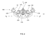
- FIG. 2 is a top view of the button component.
- FIG. 3 is a close-up view of one of the button structures in the button component.
- FIG. 4 is a close-up view of another one of the button structures in the button component.
- FIG. 5 is a close-up view of another one of the button structures in the button component.
- FIG. 6 is a bottom view of the button component.
- FIG. 7 is a side cross-sectional view of a button structure in a housing of a handheld computer, where the button structure being in a raised position.
- FIG. 8 is a side cross-sectional view of the button structure in the housing of the handheld computer, where the button structure being in a lowered position.
- FIG. 9 is a motion diagram for one of the button structures in the button component.
- FIG. 10 is a frontal view of a button structure and member joined to a button bar, under another embodiment of the invention.
- FIG. 11 is a frontal view of a button structure and member joined to a button bar, under another embodiment of the invention.
- FIG. 12 is a motion diagram of a button structure on a prior-art button component.
- FIG. 13 illustrates a handheld computer that can be used with an embodiment of the invention.
- Embodiments of the invention describe a handheld computer having integrally joined, floating buttons.
- numerous specific details are set forth in order to provide a thorough understanding of the present invention. It will be apparent, however, that the present invention may be practiced without these specific details. In other instances, well-known structures and devices are shown in block diagram form in order to avoid unnecessarily obscuring the present invention.
- a button component for a handheld includes a bar, a plurality of button structures and a plurality of members that join the button structures to the bar.
- the bar is retained within a housing of the handheld computer.
- the button structures each include a button surface that is accessible to serve as a button for a user of the handheld computer.
- each of the members join one of the button structures to the bar.
- Each of the members has a shape that enables that member to extend and retract.
- the members may be extended to enable corresponding button structures to have a substantially linear motion when traveling inward.
- the members may be extended to give the corresponding button structures freedom to move laterally.
- a linear length of each member that joins a button structure to a bar is greater than an effective length of that member.
- the added linear length may be accounted for by bending the member into a shape, and/or by joining the member to a perimeter point on the button structure that is not proximate to the bar.
- a linear length of a member corresponds to a member's length if that member was completely straight or unbent.
- An effective length of the member corresponds to a distance between opposing ends of the member in a bent state.
- each button structure includes a first perimeter point that is proximate to a point on the bar where the corresponding member is joined.
- the linear length of each corresponding member is greater than a distance between the first perimeter point and the bar.
- Each corresponding member may be joined to a button structure at a perimeter point that is radially spaced from the perimeter point, so as to add to the linear length of that member.
- the added linear length of each member joining one of the button structures to the bar is used to enable the button structures to travel in a more linear direction when moved inwards.
- the added linear lengths of those members also enable the buttons to have some movement in a lateral direction.
- the button component may be unitarily formed. That is, the bar, the button structures and members may be formed using a manufacturing process that forms the bar, the button structures, and the member.
- the bar, the button structures and the member may be a single molded component, formed from plastic or metal.
- the bar is a portion of the button component that is fixed within the housing and extends substantially in one direction. However, the bar may be curved or bent to accommodate a configuration of the button surfaces disposed on the housing of the handheld computer.
- the members are sections of the button component that extend from the bar at sharp or perpendicular angles. The members extend to the button structures.
- the button structures provide a surface that corresponds to the buttons for the handheld computer.
- the button structures have a depth that may be sufficient to enable the button surfaces to extend out of openings in the housing of the handheld computer.
- Embodiments of the invention provide certain advantages.
- the member with the added length enables the button structures to travel a more unilateral direction into the handheld computer when the button surfaces are pressed by a user.
- button structures of other handheld computers have a slightly radial movement that causes flexing in the member.
- the added length of the member enables the button structures to have some lateral freedom within their respective openings.
- the lateral freedom can be used to dislodge the buttons from the edges of the openings if the user inadvertently directs the button against the side of its opening.
- the slight radial travel of buttons in other handheld computers can cause the button surfaces to lodge against the edges of their openings, with sufficient bias to resist detachment from the edges.
- an embodiment of the invention provides for at least one of the members to join and extend between the bar and the first button structure.
- the member enables the first button structure to move into an actuated position without the button structure having to undergo a measurable radial motion about the bar.
- Measurable radial motion means that the center line of the button structure moves in a radial arc that displaces the center line by 1% or more in a lateral direction.
- the lateral direction is perpendicular to an axis of the button structure's motion.
- FIG. 1 is a front isometric view of a button component for a handheld computer, under an embodiment of the invention.
- the button component includes a plurality of button surfaces. The button surfaces protrude from a housing of the handheld computer to provide a user with buttons that can be pressed to manipulate software and enter data.
- a button component 100 includes a bar 110 , a plurality of members 120 - 130 , and a plurality of button structures 140 - 150 .
- Each button structure 140 - 150 is provided a button surface 160 - 170 that can be extended out of the handheld computer's housing.
- the disposition of the button structures 140 - 150 is primarily along an axis X.
- the bar 110 corresponds to a section of the button component 100 that extends primarily in the direction of X.
- the bar 110 may be curved or bent to conserve space, and to provide for a particular geometry for the button structures 140 - 150 .
- a first button structure 140 is joined to bar 110 by a first member 120 .
- a second button structure 142 is joined to bar 110 by a second member 122 .
- a third button structure 144 is joined to bar 110 by a third connecting member 124 .
- a fourth button structure 146 is joined to bar 110 by a fourth member 126 .
- a fifth button structure 148 is joined to bar 110 by a fifth member 128 .
- a sixth button structure 150 is joined to bar 110 by a sixth member 130 .
- Each member 120 - 130 connects to a base of the corresponding button structure.
- button structures 140 - 146 correspond to application buttons
- button structures 148 and 150 correspond to scroll or navigation buttons.
- Other configurations are possible, with a greater or less number of button structures.
- buttons 160 - 170 are what the user sees as the buttons.
- the buttons structures 140 - 150 are directed inward when the user presses corresponding button surfaces 160 - 170 .
- each button surface 160 - 170 is contoured inward, or concave about a center-line. The concavity of the buttons facilitate the button surfaces 160 - 170 in receiving contact from a stylus point.
- FIG. 2 is a top view of the button component.
- the general direction of bar 110 and disposition of button structures 140 - 150 is along axis X.
- the buttons can be pushed inward, towards the interior of the handheld computer.
- the inward direction corresponds to an axis Z (into the paper).
- the buttons may vary in position along an axis Y.
- the sixth button structure 150 is positioned adjacent to fifth button structure 148 along the axis Y to provide a scrolling relationship between the two button structures.
- FIG. 2 illustrates one embodiment where a linear length of members 120 - 130 is greater than a distance between the bar 110 and respective button structures 140 - 150 .
- the added linear length of members 120 - 130 enables portions of those members to travel without appreciably flexing about bar 110 .
- Numerous configurations are possible for button structures 140 - 150 .
- each member 120 - 130 is bent. The bent nature of the members 120 - 130 ensures that the linear length of each member is greater than the distance between the respective button structure 140 - 150 and the bar 110 .
- application buttons 140 - 146 are provided with members 120 - 126 that partially circumvent the button structures.
- the members 120 - 126 are formed into semi-circles that circumvent the button structures 140 - 146 up to about 180 degrees.
- the linear length of the semi-circular members 120 - 126 may be 50%-150% that it otherwise would be if those same members were extended linearly from bar 110 to proximate points of their corresponding button structures.
- members 120 - 126 may have greater or lesser linear lengths. For example, some of the members 120 - 126 may extend a lesser radial segment around the corresponding button structure 140 - 146 . Members 120 - 126 may partially circumvent only 45-90 degrees about corresponding button structures 140 - 146 . This would still be sufficient to enable portions of those members to travel inward with the corresponding button structures 140 - 146 when those button structures are directed inward.
- the fifth member 128 and sixth member 130 are used for the navigation buttons.
- the navigation buttons may correspond to fifth button structure 148 and sixth button structure 150 .
- the navigation buttons are used to manipulate a display by scrolling content on the display upward or downward. To accomplish this, navigation buttons are often centrally disposed on the handheld computer, at a position that is proximate to the display. In addition, the navigation buttons are typically positioned vertically, adjacent to the display. In may handheld computers, navigation buttons are generally smaller than the application buttons (corresponding to button structures 140 - 146 ), and may be provided in a more cramped location between the other buttons.
- fifth members 128 and sixth members 130 are bent, but substantially elongated in one direction (along axis Y). The bending in fifth member 128 and sixth member 130 extends portions of those members in a direction along axis X.
- sixth button structure 150 is disposed closer to bar 110 than fifth button structure 148 . This geometry enables sixth member 130 to have a longer linear length than fifth member 128 .
- one or more of the members 120 - 130 is extendible inward with the corresponding button structure 140 - 150 .
- the added linear lengths of each member 120 - 130 enable portions of those members to travel inward without flexing about bar 110 . In this way, the movement of members 120 - 130 reduces the flexing of the button structures 140 - 150 , as well as of the members 120 - 130 , about bar 110 .
- the added linear lengths of members 120 - 130 enable the motion of the button structures 140 - 150 to be more linear (along axis Z), when directed inward.
- the added linear lengths of members 120 - 130 allow for button structures 140 - 150 to be moveable in both lateral directions (along axes X and Y).
- buttons 120 - 130 were linear and connected to proximate points of corresponding button structures so as to have no added linear lengths, the travel of the button structures 140 - 150 would have a more noticeable radial movement.
- the members 120 - 130 would be cantilevering off of bar 110 when the corresponding button structures are directed inward.
- the button structures 140 - 150 would lack the lateral movement provided by embodiments of this invention.
- FIG. 3 is a close-up view of first button structure 140 , under an embodiment of the invention.
- the first button structure 140 may be exemplary of other button structures, and specifically of button structures 142 - 146 .
- the first button structure 140 has a first perimeter point 139 that is proximate to a point 111 on bar 110 .
- the point 111 is where first member 120 joins the bar 110 .
- the shortest possible length of first member 120 can be assumed to be the distance between first perimeter point 139 and point 111 of bar 110 .
- the linear length of the first member 120 is longer than this distance.
- a second perimeter point 141 of first button structure 140 corresponds to where first member 120 joins first button structure 140 .
- the first perimeter point 139 occupies a first radial position on first button structure 110
- second perimeter point 141 occupies a second radial position on first button structure 140 .
- the first perimeter point 139 and second perimeter point 141 may be 180 degrees apart.
- the first member 120 may include a circular, bent portion 119 that partially circumvents first button structure 140 .
- the linear length of first member 120 includes the shape of bent portion 119 , as well as a length to account for a difference between first and second perimeter point 139 and 141 .
- the linear length of member 120 is made to be greater than the distance between the button structure 140 and bar 110 .
- bent portion 119 may correspond to a portion of first member 120 that travels inward (along axis Z) with first button structure 140 when the first button structure is directed inward.
- the added linear length provided by bent portion 119 enables button structure 140 to have lateral and vertical freedom of motion.
- button structure 140 can be directed linearly inward along axis Z, without a cantilevering motion that flexes bar 110 .
- the second perimeter point 141 may be positioned closer to first perimeter point 139 .
- second perimeter point 141 may be positioned at 45 degrees, or 90 degrees from first perimeter point 139 .
- bent portion 119 of first member 110 may be a non-circular shape, such as coiled or with right-angle bends.
- FIG. 4 is a close-up view of fifth button structure 148 , under an embodiment of the invention.
- the fifth button structure 148 has a first perimeter point 147 that is proximate to a point 113 of bar 110 .
- the point 113 is where member fifth member 148 joins bar 110 .
- the shortest possible length of fifth member 128 is would be the distance between the first perimeter point 147 and point 113 .
- member 128 is bent to increase its linear length. In this way, the linear length of fifth member 128 is longer than the shortest distance between the button structure 148 and bar 110 .
- a second perimeter point 149 of fifth button structure 148 corresponds to where fifth member 128 joins the fifth button structure.
- the first perimeter point 147 may occupy a first radial position, and the second perimeter pint 149 may occupy a second radial position.
- first perimeter point 147 and second perimeter point 149 are between 0 and 45 degrees apart.
- the fifth member 128 includes multiple bends, including a first bend 152 and a second bend 154 .
- Each of the first and second bends 152 , 154 correspond to where fifth member 128 extends along axis X.
- the second bend 154 is u-shaped.
- the first bend 152 and second bend 154 add to the overall linear length of fifth member 128 .
- the linear length of fifth member 128 is greater than a distance between fifth button structure 148 and point 113 of bar 110 .
- the added linear length provided by fifth member 128 of member 120 enables fifth button structure 148 to have lateral and vertical freedom of motion.
- FIG. 5 is a close-up view of sixth button structure 150 , under an embodiment of the invention.
- the sixth button structure 150 is similar to fifth button structure 148 (FIG. 4 ), except sixth button structure 150 is positioned below the fifth button structure.
- the sixth member 130 has an elongated u-shaped extension 155 that extends to fifth button structure 148 , and then back to sixth button structure 150 .
- the elongated u-shaped extension 155 makes the linear length of sixth member 130 longer than a distance between the bar 110 and the sixth button structure 150 .
- the first perimeter point 151 of sixth member 130 is proximate to a point 115 on bar 110 where the sixth member is joined.
- the sixth member 130 joins sixth button structure 150 at second perimeter point 153 .
- the linear length of sixth member 130 accounts for the difference between first perimeter point 151 and second perimeter point 153 .
- the u-shaped extension 155 adds to the linear length of sixth member 130 . The result is that the linear length of the sixth member 130 is longer than the distance between point 115 and first perimeter point 151 .
- the bent portions of members 120 - 130 enables the corresponding button structures 140 - 150 to have lateral and vertical freedom within openings where the button structures are retained.
- the lateral motion of the button structures can be used to dislodge the button structures 140 - 150 from edges of their respective openings.
- the linear lengths of the members 120 - 130 give the feel that the buttons float within the housing of handheld computer.
- FIG. 6 is a bottom view of button component 100 .
- the bottom of each button structure 140 - 150 includes actuating extensions 182 .
- the actuating extension 182 of that button structure meets a conductive surface 192 (see FIGS. 7 and 8) to actuate a corresponding switch.
- Other extensions 184 act as over-travel stops for the button structures 140 - 150 .
- the extensions 184 make contact with a support structure to prevent the actuating extension 182 from over-traveling and losing contact with the conductive surface 192 .
- the button component 100 is unitarily formed. That is, one molding process is used to form the button component 100 .
- the members 120 - 130 are provided a variable thickness as they extend from bar 110 to their respective button structures 140 - 150 .
- the variable thickness may be provided by twisting rectangular cross-sectioned strips forming members 120 - 130 .
- the thicker portions of members 120 - 130 may be located where less flexibility or travel is desired.
- each member 120 - 130 includes a base stem 135 that has the greater thickness of that member.
- Each member 120 - 130 also includes one or more bent portions (see e.g. bent portion 131 of FIG. 3) having lesser thicknesses. The lesser thicknesses of the bent portions promote bending of those bent portions when corresponding button structures 140 - 150 are directed inward.
- the base stem 135 remain relatively static when the button structure is directed inward. Sections of each member adjacent to the corresponding button structures 140 - 150 , may also be twisted to have a greater thickness, thereby reducing bending of the members 120 - 130 near the corresponding button structures when those button structures travel. In this way, intermediate portions of members 120 - 130 , between bar 110 and corresponding button structures 140 - 150 , are what bend when the corresponding button structures are directed inward. This helps the button structures to have a substantially linear motion when pushed.
- FIGS. 7 and 8 illustrate button structures traveling within the housing of the handheld computer.
- first button structure 140 is described in FIGS. 7 and 8.
- the description provided for first button structure 140 is equally applicable to the other button structures 142 - 150 .
- FIG. 7 illustrates button structure 140 in a raised position.
- the bar 110 is mounted within a housing 218 of handheld computer 200 (See FIG. 9 ).
- the first button structure 140 is positioned so as to extend from an opening 212 in the housing 218 .
- the first button structure has a height to extend past an exterior surface 215 of the housing 218 .
- the axis Z is shown extending normally from button surface 160 .
- the bar 110 extends along axis X (out of the paper).
- the member 120 extends from bar 110 to a base 171 of button structure 140 .
- the member 120 includes a bent portion 131 that is not viewable from this angle.
- the member 120 joins first button structure 140 at or near base 171 .
- the first button structure 140 includes actuating extension 182 , aligned to make contact with an electrical surface 185 .
- a distance D 1 separates the actuating extension 182 from the electrical surface 185 .
- the first button structure 140 also includes over-stop extension 184 .
- the extension 184 is aligned to make contact with a stop 187 .
- a distance D 2 separates the second extension 184 from stop 187 .
- the distance D 2 may be slightly longer than distance D 1 , so that second extension 184 makes contact with stop 187 after actuating extension 182 makes contact with electrical surface 185 .
- FIG. 8 illustrates button structure 140 in a lowered or actuated position.
- extension 182 makes contact with electrical surface 185 .
- the second extension 184 is positioned to be slightly separated from stop 187 . If button structure 140 is pushed so as to pivot about extension 182 , extension 184 contacts stop 187 and stabilizes the button structure by preventing further pivoting.
- first member 120 bends to enable first button structure 140 to travel in a substantially linear direction along axis Z.
- the first button structure 140 can be directed inward without radial movement about bar 110 .
- a portion of first member 120 bends and travels with first button structure 140 to enable the substantially linear motion.
- a portion of first member 120 near the bar 110 remains substantially undeformed when the first button structure 140 is directed inward.
- FIG. 9 is a motion diagram illustrating the freedom of motion for first button structure 140 within a corresponding housing opening. The description of the movement of first button structure 140 may be applicable to the other button structures as well.
- first button structure 140 is capable of linear motion about axis Z.
- first button structure 140 is capable of lateral motion along axes X and Y (out of the paper).
- the different motions of the button structure is made possible by the linear length of first member 120 .
- the first member 120 can deform, bend and travel with the first button structure so that first button 140 can maintain a linear motion, with little flex on bar 110 .
- first button member 140 can be directed inward, into a lowered or actuated position, without any measurable radial motion about the bar 110 .
- the linear length and mobility of first member 120 also enables first button structure 140 to move laterally within the opening 212 of the handheld computer 200 .
- FIGS. 10-11 illustrate alternative configurations for a member that connects to a button structure 340 of handheld computer 200 .
- a member 330 is one bend 332 , but is extended from bar 310 so that its linear length is substantially more than required if a linear segment was extended from the bar 310 to a proximate point 331 .
- the connection point 333 between the member 330 and the button structure 340 may be apart from where the proximate point 331 is, so as to add to the linear length of the member 330 .
- FIG. 11 illustrates another embodiment where member 330 ′ is zig-zagged to provide it with sufficient linear length to enable the button structure to have a substantially linear motion.
- Other configurations for the shape of members joining button structures to the bar can be contemplated.
Abstract
Description
Claims (40)
Priority Applications (1)
| Application Number | Priority Date | Filing Date | Title |
|---|---|---|---|
| US09/957,192 US6552282B2 (en) | 2001-09-19 | 2001-09-19 | Floating button design for a handheld computer |
Applications Claiming Priority (1)
| Application Number | Priority Date | Filing Date | Title |
|---|---|---|---|
| US09/957,192 US6552282B2 (en) | 2001-09-19 | 2001-09-19 | Floating button design for a handheld computer |
Publications (2)
| Publication Number | Publication Date |
|---|---|
| US20030051982A1 US20030051982A1 (en) | 2003-03-20 |
| US6552282B2 true US6552282B2 (en) | 2003-04-22 |
Family
ID=25499205
Family Applications (1)
| Application Number | Title | Priority Date | Filing Date |
|---|---|---|---|
| US09/957,192 Expired - Lifetime US6552282B2 (en) | 2001-09-19 | 2001-09-19 | Floating button design for a handheld computer |
Country Status (1)
| Country | Link |
|---|---|
| US (1) | US6552282B2 (en) |
Cited By (18)
| Publication number | Priority date | Publication date | Assignee | Title |
|---|---|---|---|---|
| US20030164281A1 (en) * | 2002-03-01 | 2003-09-04 | Jun Hiraoka | Key device |
| US20040008186A1 (en) * | 2000-11-14 | 2004-01-15 | Mcalindon Peter J. | Apparatus and method for generating data signals |
| US20040015021A1 (en) * | 2000-04-03 | 2004-01-22 | Adams Paul E. | Lubricant compositions containing ester-substituted hindered phenol antioxidants |
| US20040227728A1 (en) * | 2000-11-14 | 2004-11-18 | Mcalindon Peter J. | Apparatus and method for generating data signals |
| US20050178167A1 (en) * | 2004-02-13 | 2005-08-18 | Kim Jae K. | Window assembly for electric home appliance and control panel assembly usingg the same |
| US20050178166A1 (en) * | 2004-02-13 | 2005-08-18 | Kim Jae K. | Button assembly for electric home appliance and control panel assembly using the same |
| US20060001648A1 (en) * | 2004-06-01 | 2006-01-05 | Lg Electronics Inc. | Button assembly of control panel assembly |
| US20060291938A1 (en) * | 2003-06-27 | 2006-12-28 | Mcalindon Peter J | Apparatus And Method For Generating Data Signals |
| US20070099482A1 (en) * | 2005-10-27 | 2007-05-03 | Inventec Appliances Corp. | Resilient switch |
| US20070221489A1 (en) * | 2006-03-21 | 2007-09-27 | Chin-Sheng Liu | Elastic strip used in electronic device |
| US20070281747A1 (en) * | 2006-05-31 | 2007-12-06 | Velimir Pletikosa | Keyboard for Mobile Device |
| US20100025214A1 (en) * | 2008-07-31 | 2010-02-04 | Electrolux Home Products | Unitized Appliance Control Panel Assembly and Components of the Assembly |
| US20120132509A1 (en) * | 2010-11-26 | 2012-05-31 | Ricoh Company, Ltd. | Keypad assembly, and image forming device and data processor incorporating the same |
| US20120147570A1 (en) * | 2010-12-14 | 2012-06-14 | Yamaha Corporation | Switch structure, electronic component part installing structure, and electronic musical instrument including the same |
| US20120315872A1 (en) * | 2003-09-18 | 2012-12-13 | At&T Intellectual Property I, Lp | Methods, systems, and computer-readable-mediums for managing rollover usage units of communication services |
| US8487872B2 (en) | 2000-11-14 | 2013-07-16 | Blue Orb, Inc. | Apparatus and method for generating data signals |
| US20130256107A1 (en) * | 2012-04-02 | 2013-10-03 | Hon Hai Precision Industry Co., Ltd. | Button mechanism and electronic device using the same |
| DE102008038568B4 (en) * | 2008-08-20 | 2017-07-20 | Leopold Kostal Gmbh & Co. Kg | Arrangement of several actuators for pushbuttons or pressure switches, as well as device with such an arrangement |
Families Citing this family (2)
| Publication number | Priority date | Publication date | Assignee | Title |
|---|---|---|---|---|
| TWI232398B (en) * | 2004-02-12 | 2005-05-11 | Asustek Comp Inc | Electronic apparatus and button structure |
| WO2017120780A1 (en) * | 2016-01-13 | 2017-07-20 | 邢皓宇 | Camera for pets |
Citations (57)
| Publication number | Priority date | Publication date | Assignee | Title |
|---|---|---|---|---|
| US1148721A (en) | 1915-02-06 | 1915-08-03 | Richard D Scott | Cap for type-writer key-levers. |
| US3612802A (en) | 1968-09-23 | 1971-10-12 | Int Standard Electric Corp | Pushbutton array |
| US3744034A (en) | 1972-01-27 | 1973-07-03 | Perkin Elmer Corp | Method and apparatus for providing a security system for a computer |
| US4132877A (en) | 1974-10-31 | 1979-01-02 | Litton Business Systems, Inc. | Removable keyboard switch |
| US4315114A (en) | 1980-03-24 | 1982-02-09 | International Telephone And Telegraph Corporation | Keyboard switch assembly |
| US4323740A (en) | 1980-02-04 | 1982-04-06 | Rogers Corporation | Keyboard actuator device and keyboard incorporating the device |
| US4389549A (en) | 1981-11-23 | 1983-06-21 | Cts Corporation | Side actuated miniature dip switch |
| US4396963A (en) | 1981-03-31 | 1983-08-02 | Disctron | Access door latch and interlock mechanism |
| USD276334S (en) | 1981-05-22 | 1984-11-13 | Dickerson William R | Control panel |
| US4819893A (en) | 1987-10-16 | 1989-04-11 | Matsuo Kogyo Kabushiki Kaisha | Clutch mechanism thumb button mounting for fishing reel |
| US4860372A (en) | 1985-08-28 | 1989-08-22 | Hitachi, Ltd. | Real time handwritten character input system |
| US4887129A (en) | 1986-05-12 | 1989-12-12 | Shenoy Vittal U | Editing copying machine |
| US4972496A (en) | 1986-07-25 | 1990-11-20 | Grid Systems Corporation | Handwritten keyboardless entry computer system |
| US5067573A (en) | 1989-12-27 | 1991-11-26 | Sony Corporation | Hand-writing input apparatus |
| US5219067A (en) | 1992-02-04 | 1993-06-15 | Trimble Navigation Limited | Keyboard pad structure for electronic devices |
| US5231381A (en) | 1989-10-02 | 1993-07-27 | U.S. Philips Corp. | Data processing system with a touch screen and a digitizing tablet, both integrated in an input device |
| USD338191S (en) | 1990-05-09 | 1993-08-10 | Chrysler Corporation | Power seat control unit for vehicular driver and passenger seats |
| US5293018A (en) | 1991-08-29 | 1994-03-08 | Marquardt Gmbh | Electric switch |
| US5305394A (en) | 1991-04-30 | 1994-04-19 | Sony Corporation | Character inputting apparatus |
| US5329276A (en) | 1990-12-19 | 1994-07-12 | Kabushiki Kaisha Yaskawa Denki | Multidimensional signal input device |
| US5357071A (en) | 1992-03-24 | 1994-10-18 | Kabushiki Kaisha Tokai Rika Denki Seisakusho | Switch device having structure for minimizing vibration of an operating knob |
| US5372607A (en) | 1993-06-23 | 1994-12-13 | Medtronic, Inc. | Method and apparatus for monitoring pacemaker intervals |
| US5389745A (en) | 1991-09-11 | 1995-02-14 | Kabushiki Kaisha Toshiba | Handwriting input apparatus for inputting handwritten data from unspecified direction |
| US5413234A (en) | 1992-02-12 | 1995-05-09 | Continental White Cap, Inc. | Tamper evident closure |
| US5423227A (en) | 1991-10-30 | 1995-06-13 | U.S. Philips Corporation | Device for generating multi-directional commands |
| US5426275A (en) | 1992-08-04 | 1995-06-20 | Alps Electric Co., Ltd. | Seesaw switch |
| US5434929A (en) | 1994-07-12 | 1995-07-18 | Apple Computer, Inc. | Method and apparatus for setting character style preferences in a pen-based computer system |
| US5438662A (en) | 1990-11-12 | 1995-08-01 | Eden Group Limited | Electronic display and data processing apparatus for displaying text and graphics in a ring binder representation |
| US5444192A (en) | 1993-07-01 | 1995-08-22 | Integral Information Systems | Interactive data entry apparatus |
| US5452371A (en) | 1992-05-27 | 1995-09-19 | Apple Computer, Inc. | Method of aligning shapes on a display of a computer system |
| US5481074A (en) * | 1992-08-18 | 1996-01-02 | Key Tronic Corporation | Computer keyboard with cantilever switch and actuator design |
| USD369143S (en) | 1994-06-07 | 1996-04-23 | Carlingswitch, Inc. | Rocker switch bezel and actuator |
| US5528743A (en) | 1993-05-27 | 1996-06-18 | Apple Computer, Inc. | Method and apparatus for inserting text on a pen-based computer system |
| US5528235A (en) | 1991-09-03 | 1996-06-18 | Edward D. Lin | Multi-status multi-function data processing key and key array |
| US5534892A (en) | 1992-05-20 | 1996-07-09 | Sharp Kabushiki Kaisha | Display-integrated type tablet device having and idle time in one display image frame to detect coordinates and having different electrode densities |
| US5560475A (en) | 1994-12-14 | 1996-10-01 | Brundage; Douglas L. | Illuminated rocker buttons with light dams |
| US5563996A (en) | 1992-04-13 | 1996-10-08 | Apple Computer, Inc. | Computer note pad including gesture based note division tools and method |
| US5615284A (en) | 1993-11-29 | 1997-03-25 | International Business Machines Corporation | Stylus-input recognition correction manager computer program product |
| US5630148A (en) | 1994-06-17 | 1997-05-13 | Intel Corporation | Dynamic processor performance and power management in a computer system |
| US5629837A (en) | 1995-09-20 | 1997-05-13 | Oz Technologies, Inc. | Button contact for surface mounting an IC device to a circuit board |
| US5629832A (en) | 1994-06-16 | 1997-05-13 | Compaq Computer Corporation | Electronic device keyboard with pivot bar tilt mechanism |
| US5698822A (en) | 1994-05-16 | 1997-12-16 | Sharp Kabushiki Kaisha | Input and display apparatus for handwritten characters |
| US5710398A (en) | 1996-05-20 | 1998-01-20 | Delco Electronics Corporation | Hinged push button cluster |
| US5718326A (en) | 1996-07-22 | 1998-02-17 | Delco Electronics Corporation | Backlit button/switchpad assembly |
| US5724492A (en) | 1995-06-08 | 1998-03-03 | Microsoft Corporation | Systems and method for displaying control objects including a plurality of panels |
| US5734130A (en) | 1993-07-21 | 1998-03-31 | International Business Machines Corporation | Digitizing apparatus having array of hall effect sensors |
| US5749457A (en) | 1996-12-23 | 1998-05-12 | Motorola Inc. | Electronic device with switch and pivotable actuator assembly |
| US5825675A (en) | 1993-07-29 | 1998-10-20 | Xerox Corporation | Apparatus and configuration method for a small, hand-held computing device |
| US5841901A (en) | 1992-05-27 | 1998-11-24 | Hitachi, Ltd. | Pattern recognition system |
| US5900875A (en) | 1997-01-29 | 1999-05-04 | 3Com Corporation | Method and apparatus for interacting with a portable computer system |
| US5923317A (en) | 1997-06-17 | 1999-07-13 | Thrustmaster, Inc. | Two-handed controller for video games and simulations |
| US5927483A (en) | 1997-03-31 | 1999-07-27 | Nec Corporation | Switch structure of electronic device |
| US5982356A (en) | 1997-10-15 | 1999-11-09 | Akiyama; Robert | Ergonomic computer cursor control apparatus and mount |
| US5996080A (en) | 1995-10-04 | 1999-11-30 | Norand Corporation | Safe, virtual trigger for a portable data capture terminal |
| US6034685A (en) | 1995-02-24 | 2000-03-07 | Casio Computer Co., Ltd. | Data inputting devices |
| US6064342A (en) | 1998-07-13 | 2000-05-16 | 3Com Corporation | Antenna detachment mechanisms and methods |
| US6147314A (en) * | 1998-11-30 | 2000-11-14 | Palm, Inc. | Button pivot bar |
-
2001
- 2001-09-19 US US09/957,192 patent/US6552282B2/en not_active Expired - Lifetime
Patent Citations (58)
| Publication number | Priority date | Publication date | Assignee | Title |
|---|---|---|---|---|
| US1148721A (en) | 1915-02-06 | 1915-08-03 | Richard D Scott | Cap for type-writer key-levers. |
| US3612802A (en) | 1968-09-23 | 1971-10-12 | Int Standard Electric Corp | Pushbutton array |
| US3744034A (en) | 1972-01-27 | 1973-07-03 | Perkin Elmer Corp | Method and apparatus for providing a security system for a computer |
| US4132877A (en) | 1974-10-31 | 1979-01-02 | Litton Business Systems, Inc. | Removable keyboard switch |
| US4323740A (en) | 1980-02-04 | 1982-04-06 | Rogers Corporation | Keyboard actuator device and keyboard incorporating the device |
| US4315114A (en) | 1980-03-24 | 1982-02-09 | International Telephone And Telegraph Corporation | Keyboard switch assembly |
| US4396963A (en) | 1981-03-31 | 1983-08-02 | Disctron | Access door latch and interlock mechanism |
| USD276334S (en) | 1981-05-22 | 1984-11-13 | Dickerson William R | Control panel |
| US4389549A (en) | 1981-11-23 | 1983-06-21 | Cts Corporation | Side actuated miniature dip switch |
| US4860372A (en) | 1985-08-28 | 1989-08-22 | Hitachi, Ltd. | Real time handwritten character input system |
| US4887129A (en) | 1986-05-12 | 1989-12-12 | Shenoy Vittal U | Editing copying machine |
| US4972496A (en) | 1986-07-25 | 1990-11-20 | Grid Systems Corporation | Handwritten keyboardless entry computer system |
| US4819893A (en) | 1987-10-16 | 1989-04-11 | Matsuo Kogyo Kabushiki Kaisha | Clutch mechanism thumb button mounting for fishing reel |
| US5231381A (en) | 1989-10-02 | 1993-07-27 | U.S. Philips Corp. | Data processing system with a touch screen and a digitizing tablet, both integrated in an input device |
| US5067573A (en) | 1989-12-27 | 1991-11-26 | Sony Corporation | Hand-writing input apparatus |
| USD338191S (en) | 1990-05-09 | 1993-08-10 | Chrysler Corporation | Power seat control unit for vehicular driver and passenger seats |
| US5438662A (en) | 1990-11-12 | 1995-08-01 | Eden Group Limited | Electronic display and data processing apparatus for displaying text and graphics in a ring binder representation |
| US5329276A (en) | 1990-12-19 | 1994-07-12 | Kabushiki Kaisha Yaskawa Denki | Multidimensional signal input device |
| US5305394A (en) | 1991-04-30 | 1994-04-19 | Sony Corporation | Character inputting apparatus |
| US5293018A (en) | 1991-08-29 | 1994-03-08 | Marquardt Gmbh | Electric switch |
| US5528235A (en) | 1991-09-03 | 1996-06-18 | Edward D. Lin | Multi-status multi-function data processing key and key array |
| US5389745A (en) | 1991-09-11 | 1995-02-14 | Kabushiki Kaisha Toshiba | Handwriting input apparatus for inputting handwritten data from unspecified direction |
| US5423227A (en) | 1991-10-30 | 1995-06-13 | U.S. Philips Corporation | Device for generating multi-directional commands |
| US5219067A (en) | 1992-02-04 | 1993-06-15 | Trimble Navigation Limited | Keyboard pad structure for electronic devices |
| US5413234A (en) | 1992-02-12 | 1995-05-09 | Continental White Cap, Inc. | Tamper evident closure |
| US5357071A (en) | 1992-03-24 | 1994-10-18 | Kabushiki Kaisha Tokai Rika Denki Seisakusho | Switch device having structure for minimizing vibration of an operating knob |
| US5563996A (en) | 1992-04-13 | 1996-10-08 | Apple Computer, Inc. | Computer note pad including gesture based note division tools and method |
| US5534892A (en) | 1992-05-20 | 1996-07-09 | Sharp Kabushiki Kaisha | Display-integrated type tablet device having and idle time in one display image frame to detect coordinates and having different electrode densities |
| US5452371A (en) | 1992-05-27 | 1995-09-19 | Apple Computer, Inc. | Method of aligning shapes on a display of a computer system |
| US5841901A (en) | 1992-05-27 | 1998-11-24 | Hitachi, Ltd. | Pattern recognition system |
| US5621817A (en) | 1992-05-27 | 1997-04-15 | Apple Computer, Inc. | Pointer-based computer system capable of aligning geometric figures |
| US5426275A (en) | 1992-08-04 | 1995-06-20 | Alps Electric Co., Ltd. | Seesaw switch |
| US5481074A (en) * | 1992-08-18 | 1996-01-02 | Key Tronic Corporation | Computer keyboard with cantilever switch and actuator design |
| US5528743A (en) | 1993-05-27 | 1996-06-18 | Apple Computer, Inc. | Method and apparatus for inserting text on a pen-based computer system |
| US5372607A (en) | 1993-06-23 | 1994-12-13 | Medtronic, Inc. | Method and apparatus for monitoring pacemaker intervals |
| US5444192A (en) | 1993-07-01 | 1995-08-22 | Integral Information Systems | Interactive data entry apparatus |
| US5734130A (en) | 1993-07-21 | 1998-03-31 | International Business Machines Corporation | Digitizing apparatus having array of hall effect sensors |
| US5825675A (en) | 1993-07-29 | 1998-10-20 | Xerox Corporation | Apparatus and configuration method for a small, hand-held computing device |
| US5615284A (en) | 1993-11-29 | 1997-03-25 | International Business Machines Corporation | Stylus-input recognition correction manager computer program product |
| US5698822A (en) | 1994-05-16 | 1997-12-16 | Sharp Kabushiki Kaisha | Input and display apparatus for handwritten characters |
| USD369143S (en) | 1994-06-07 | 1996-04-23 | Carlingswitch, Inc. | Rocker switch bezel and actuator |
| US5629832A (en) | 1994-06-16 | 1997-05-13 | Compaq Computer Corporation | Electronic device keyboard with pivot bar tilt mechanism |
| US5630148A (en) | 1994-06-17 | 1997-05-13 | Intel Corporation | Dynamic processor performance and power management in a computer system |
| US5434929A (en) | 1994-07-12 | 1995-07-18 | Apple Computer, Inc. | Method and apparatus for setting character style preferences in a pen-based computer system |
| US5560475A (en) | 1994-12-14 | 1996-10-01 | Brundage; Douglas L. | Illuminated rocker buttons with light dams |
| US6034685A (en) | 1995-02-24 | 2000-03-07 | Casio Computer Co., Ltd. | Data inputting devices |
| US5724492A (en) | 1995-06-08 | 1998-03-03 | Microsoft Corporation | Systems and method for displaying control objects including a plurality of panels |
| US5629837A (en) | 1995-09-20 | 1997-05-13 | Oz Technologies, Inc. | Button contact for surface mounting an IC device to a circuit board |
| US5996080A (en) | 1995-10-04 | 1999-11-30 | Norand Corporation | Safe, virtual trigger for a portable data capture terminal |
| US5710398A (en) | 1996-05-20 | 1998-01-20 | Delco Electronics Corporation | Hinged push button cluster |
| US5718326A (en) | 1996-07-22 | 1998-02-17 | Delco Electronics Corporation | Backlit button/switchpad assembly |
| US5749457A (en) | 1996-12-23 | 1998-05-12 | Motorola Inc. | Electronic device with switch and pivotable actuator assembly |
| US5900875A (en) | 1997-01-29 | 1999-05-04 | 3Com Corporation | Method and apparatus for interacting with a portable computer system |
| US5927483A (en) | 1997-03-31 | 1999-07-27 | Nec Corporation | Switch structure of electronic device |
| US5923317A (en) | 1997-06-17 | 1999-07-13 | Thrustmaster, Inc. | Two-handed controller for video games and simulations |
| US5982356A (en) | 1997-10-15 | 1999-11-09 | Akiyama; Robert | Ergonomic computer cursor control apparatus and mount |
| US6064342A (en) | 1998-07-13 | 2000-05-16 | 3Com Corporation | Antenna detachment mechanisms and methods |
| US6147314A (en) * | 1998-11-30 | 2000-11-14 | Palm, Inc. | Button pivot bar |
Non-Patent Citations (6)
| Title |
|---|
| Bursky, D., "Evolving DSP chips do more", Electronic Design, vol. 38, No. 23, pp 51-59, Dec. 1990. |
| Dayton, D., "FRx extends reporting power of Platinum Series", PC Week, vol. 8, No. 5, p 29(2), Feb. 1991. |
| Feigel, C., "IBM, Motorola preview embedded PowerPCs; 402 and 505 processors combine strong performance with low cost", Microprocessor Report, vol. 8, No. 6, pp 1-5, May 1994. |
| Forbes, J., et al., "Palm PCs get a Big Hand (What's Hot)", Windows Magazine, No. 905, p 96, May 1998. |
| Gray, R. et al., "Efficient MC68HC08 programming: reducing cycle count and improving code density", Dr. Dobb's Journal, vol. 20, No. 5, May 1995, pp 70-75. |
| Penwarden, J., "More Muscle for HP's OminiBook", Windows Magazine, No. 501, p. 110, Jan. 1994. |
Cited By (33)
| Publication number | Priority date | Publication date | Assignee | Title |
|---|---|---|---|---|
| US20040015021A1 (en) * | 2000-04-03 | 2004-01-22 | Adams Paul E. | Lubricant compositions containing ester-substituted hindered phenol antioxidants |
| US8487872B2 (en) | 2000-11-14 | 2013-07-16 | Blue Orb, Inc. | Apparatus and method for generating data signals |
| US7151525B2 (en) | 2000-11-14 | 2006-12-19 | Keybowl, Inc. | Apparatus and method for generating data signals |
| US20040227728A1 (en) * | 2000-11-14 | 2004-11-18 | Mcalindon Peter J. | Apparatus and method for generating data signals |
| US7262762B2 (en) | 2000-11-14 | 2007-08-28 | Keybowl, Inc. | Apparatus and method for generating data signals |
| US20040008186A1 (en) * | 2000-11-14 | 2004-01-15 | Mcalindon Peter J. | Apparatus and method for generating data signals |
| US6835902B2 (en) * | 2002-03-01 | 2004-12-28 | Sharp Kabushiki Kaisha | Peripheral and central key apparatus |
| US20030164281A1 (en) * | 2002-03-01 | 2003-09-04 | Jun Hiraoka | Key device |
| US20060291937A1 (en) * | 2003-06-27 | 2006-12-28 | Mcalindon Peter J | Apparatus And Method For Generating Data signals |
| US20060291938A1 (en) * | 2003-06-27 | 2006-12-28 | Mcalindon Peter J | Apparatus And Method For Generating Data Signals |
| US20060291939A1 (en) * | 2003-06-27 | 2006-12-28 | Mcalindon Peter J | Apparatus And Method For Generating Data Signals |
| US20070020013A1 (en) * | 2003-06-27 | 2007-01-25 | Mcalindon Peter J | Apparatus And Method For Generating Data Signals |
| US8614667B2 (en) | 2003-06-27 | 2013-12-24 | Blue Orb, Inc. | Apparatus and method for generating data signals |
| US8588737B2 (en) * | 2003-09-18 | 2013-11-19 | At&T Intellectual Property I, L.P. | Methods, systems, and computer-readable-mediums for managing rollover usage units of communication services |
| US20120315872A1 (en) * | 2003-09-18 | 2012-12-13 | At&T Intellectual Property I, Lp | Methods, systems, and computer-readable-mediums for managing rollover usage units of communication services |
| US20050178167A1 (en) * | 2004-02-13 | 2005-08-18 | Kim Jae K. | Window assembly for electric home appliance and control panel assembly usingg the same |
| US20050178166A1 (en) * | 2004-02-13 | 2005-08-18 | Kim Jae K. | Button assembly for electric home appliance and control panel assembly using the same |
| US7265309B2 (en) * | 2004-06-01 | 2007-09-04 | Lg Electronics Inc. | Button assembly of control panel assembly |
| US20060001648A1 (en) * | 2004-06-01 | 2006-01-05 | Lg Electronics Inc. | Button assembly of control panel assembly |
| US20070099482A1 (en) * | 2005-10-27 | 2007-05-03 | Inventec Appliances Corp. | Resilient switch |
| US7342192B2 (en) * | 2005-10-27 | 2008-03-11 | Inventec Appliances Corp. | Resilient switch |
| US20070221489A1 (en) * | 2006-03-21 | 2007-09-27 | Chin-Sheng Liu | Elastic strip used in electronic device |
| US7414215B2 (en) * | 2006-03-21 | 2008-08-19 | Behavior Tech Computer Corp. | Elastic strip used in electronic device |
| US7953448B2 (en) * | 2006-05-31 | 2011-05-31 | Research In Motion Limited | Keyboard for mobile device |
| US20070281747A1 (en) * | 2006-05-31 | 2007-12-06 | Velimir Pletikosa | Keyboard for Mobile Device |
| US8178802B2 (en) | 2008-07-31 | 2012-05-15 | Electrolux Home Products, Inc. | Unitized appliance control panel assembly and components of the assembly |
| US20100025214A1 (en) * | 2008-07-31 | 2010-02-04 | Electrolux Home Products | Unitized Appliance Control Panel Assembly and Components of the Assembly |
| DE102008038568B4 (en) * | 2008-08-20 | 2017-07-20 | Leopold Kostal Gmbh & Co. Kg | Arrangement of several actuators for pushbuttons or pressure switches, as well as device with such an arrangement |
| US20120132509A1 (en) * | 2010-11-26 | 2012-05-31 | Ricoh Company, Ltd. | Keypad assembly, and image forming device and data processor incorporating the same |
| US8618429B2 (en) * | 2010-11-26 | 2013-12-31 | Ricoh Company, Ltd. | Keypad assembly, and image forming device and data processor incorporating the same |
| US20120147570A1 (en) * | 2010-12-14 | 2012-06-14 | Yamaha Corporation | Switch structure, electronic component part installing structure, and electronic musical instrument including the same |
| US8693201B2 (en) * | 2010-12-14 | 2014-04-08 | Yamaha Corporation | Switch structure, electronic component part installing structure, and electronic musical instrument including the same |
| US20130256107A1 (en) * | 2012-04-02 | 2013-10-03 | Hon Hai Precision Industry Co., Ltd. | Button mechanism and electronic device using the same |
Also Published As
| Publication number | Publication date |
|---|---|
| US20030051982A1 (en) | 2003-03-20 |
Similar Documents
| Publication | Publication Date | Title |
|---|---|---|
| US6552282B2 (en) | Floating button design for a handheld computer | |
| CN101894696B (en) | Key switch unit | |
| US5901837A (en) | Push button switch and manufacturing method of the same | |
| US20010014010A1 (en) | Handheld computer configured for attachment with an external device | |
| CN110471561B (en) | Touch control device | |
| US20100304793A1 (en) | Mobile device having two touch screen display panels | |
| US7345253B2 (en) | Key structures | |
| US6781077B2 (en) | Keyswitch and actuator structure | |
| JPH08171835A (en) | Key switch | |
| JPH0927235A (en) | Key switch and keyboard having the same | |
| CN1205632C (en) | Multiple direction operational and controlled key button | |
| JPH0992079A (en) | Low-stroke film disc spring | |
| CN214378148U (en) | Key structure | |
| KR200229591Y1 (en) | multi-directional tact switch | |
| US6762379B1 (en) | Micro switch | |
| US20240120157A1 (en) | Keyswitch structure | |
| KR101120159B1 (en) | Hinge device for mobile phone of folding type | |
| CN218100196U (en) | Touch module supporting component and notebook computer | |
| CN1202698C (en) | Cover possessing three-stage structure | |
| JP2000228129A (en) | Key switch device | |
| CN117666818A (en) | Touch control panel device | |
| WO2002055899A2 (en) | Spring | |
| CN1129834C (en) | Buttons | |
| JP3352680B2 (en) | Key switch device | |
| JP3295072B2 (en) | Key switch device |
Legal Events
| Date | Code | Title | Description |
|---|---|---|---|
| AS | Assignment |
Owner name: PALM, INC., CALIFORNIA Free format text: ASSIGNMENT OF ASSIGNORS INTEREST;ASSIGNOR:LEWIS, TODD;REEL/FRAME:012589/0266 Effective date: 20011226 |
|
| STCF | Information on status: patent grant |
Free format text: PATENTED CASE |
|
| FPAY | Fee payment |
Year of fee payment: 4 |
|
| FEPP | Fee payment procedure |
Free format text: PAYER NUMBER DE-ASSIGNED (ORIGINAL EVENT CODE: RMPN); ENTITY STATUS OF PATENT OWNER: LARGE ENTITY Free format text: PAYOR NUMBER ASSIGNED (ORIGINAL EVENT CODE: ASPN); ENTITY STATUS OF PATENT OWNER: LARGE ENTITY |
|
| AS | Assignment |
Owner name: JPMORGAN CHASE BANK, N.A., NEW YORK Free format text: SECURITY AGREEMENT;ASSIGNOR:PALM, INC.;REEL/FRAME:020317/0256 Effective date: 20071024 |
|
| AS | Assignment |
Owner name: PALM, INC., CALIFORNIA Free format text: RELEASE BY SECURED PARTY;ASSIGNOR:JPMORGAN CHASE BANK, N.A., AS ADMINISTRATIVE AGENT;REEL/FRAME:024630/0474 Effective date: 20100701 |
|
| FPAY | Fee payment |
Year of fee payment: 8 |
|
| AS | Assignment |
Owner name: HEWLETT-PACKARD DEVELOPMENT COMPANY, L.P., TEXAS Free format text: ASSIGNMENT OF ASSIGNORS INTEREST;ASSIGNOR:PALM, INC.;REEL/FRAME:025204/0809 Effective date: 20101027 |
|
| AS | Assignment |
Owner name: PALM, INC., CALIFORNIA Free format text: ASSIGNMENT OF ASSIGNORS INTEREST;ASSIGNOR:HEWLETT-PACKARD DEVELOPMENT COMPANY, L.P.;REEL/FRAME:030341/0459 Effective date: 20130430 |
|
| FEPP | Fee payment procedure |
Free format text: PAYER NUMBER DE-ASSIGNED (ORIGINAL EVENT CODE: RMPN); ENTITY STATUS OF PATENT OWNER: LARGE ENTITY Free format text: PAYOR NUMBER ASSIGNED (ORIGINAL EVENT CODE: ASPN); ENTITY STATUS OF PATENT OWNER: LARGE ENTITY |
|
| AS | Assignment |
Owner name: HEWLETT-PACKARD DEVELOPMENT COMPANY, L.P., TEXAS Free format text: ASSIGNMENT OF ASSIGNORS INTEREST;ASSIGNOR:PALM, INC.;REEL/FRAME:031837/0239 Effective date: 20131218 Owner name: HEWLETT-PACKARD DEVELOPMENT COMPANY, L.P., TEXAS Free format text: ASSIGNMENT OF ASSIGNORS INTEREST;ASSIGNOR:PALM, INC.;REEL/FRAME:031837/0659 Effective date: 20131218 Owner name: PALM, INC., CALIFORNIA Free format text: ASSIGNMENT OF ASSIGNORS INTEREST;ASSIGNOR:HEWLETT-PACKARD DEVELOPMENT COMPANY, L.P.;REEL/FRAME:031837/0544 Effective date: 20131218 |
|
| AS | Assignment |
Owner name: QUALCOMM INCORPORATED, CALIFORNIA Free format text: ASSIGNMENT OF ASSIGNORS INTEREST;ASSIGNORS:HEWLETT-PACKARD COMPANY;HEWLETT-PACKARD DEVELOPMENT COMPANY, L.P.;PALM, INC.;REEL/FRAME:032132/0001 Effective date: 20140123 |
|
| FPAY | Fee payment |
Year of fee payment: 12 |