US6547343B1 - Brake system control - Google Patents
Brake system control Download PDFInfo
- Publication number
- US6547343B1 US6547343B1 US08/925,247 US92524797A US6547343B1 US 6547343 B1 US6547343 B1 US 6547343B1 US 92524797 A US92524797 A US 92524797A US 6547343 B1 US6547343 B1 US 6547343B1
- Authority
- US
- United States
- Prior art keywords
- vehicle
- responsive
- slip angle
- lateral
- yaw rate
- Prior art date
- Legal status (The legal status is an assumption and is not a legal conclusion. Google has not performed a legal analysis and makes no representation as to the accuracy of the status listed.)
- Expired - Fee Related, expires
Links
- 230000001133 acceleration Effects 0.000 claims abstract description 50
- 238000000034 method Methods 0.000 claims abstract description 16
- 230000006870 function Effects 0.000 claims description 48
- 238000005312 nonlinear dynamic Methods 0.000 claims description 3
- 238000001914 filtration Methods 0.000 claims 1
- 230000007423 decrease Effects 0.000 description 8
- 238000004364 calculation method Methods 0.000 description 7
- 238000009826 distribution Methods 0.000 description 7
- 230000005484 gravity Effects 0.000 description 7
- 230000033001 locomotion Effects 0.000 description 7
- 230000009467 reduction Effects 0.000 description 7
- 238000004422 calculation algorithm Methods 0.000 description 4
- 238000012937 correction Methods 0.000 description 4
- 238000013016 damping Methods 0.000 description 4
- 230000001419 dependent effect Effects 0.000 description 4
- 230000000694 effects Effects 0.000 description 4
- 230000004044 response Effects 0.000 description 4
- 230000004913 activation Effects 0.000 description 3
- 238000013459 approach Methods 0.000 description 3
- 238000010586 diagram Methods 0.000 description 3
- 239000012530 fluid Substances 0.000 description 3
- 238000005259 measurement Methods 0.000 description 3
- 230000002829 reductive effect Effects 0.000 description 3
- 238000012546 transfer Methods 0.000 description 3
- 230000008878 coupling Effects 0.000 description 2
- 238000010168 coupling process Methods 0.000 description 2
- 238000005859 coupling reaction Methods 0.000 description 2
- 230000003247 decreasing effect Effects 0.000 description 2
- 230000000994 depressogenic effect Effects 0.000 description 2
- 230000036961 partial effect Effects 0.000 description 2
- 230000008569 process Effects 0.000 description 2
- 238000005070 sampling Methods 0.000 description 2
- 239000000725 suspension Substances 0.000 description 2
- 238000012360 testing method Methods 0.000 description 2
- 230000003213 activating effect Effects 0.000 description 1
- 230000008901 benefit Effects 0.000 description 1
- 230000005540 biological transmission Effects 0.000 description 1
- 238000002485 combustion reaction Methods 0.000 description 1
- 230000004069 differentiation Effects 0.000 description 1
- 230000014509 gene expression Effects 0.000 description 1
- 230000002401 inhibitory effect Effects 0.000 description 1
- 230000000670 limiting effect Effects 0.000 description 1
- 238000005096 rolling process Methods 0.000 description 1
- 238000013519 translation Methods 0.000 description 1
- 230000001960 triggered effect Effects 0.000 description 1
Images


Classifications
-
- B—PERFORMING OPERATIONS; TRANSPORTING
- B60—VEHICLES IN GENERAL
- B60T—VEHICLE BRAKE CONTROL SYSTEMS OR PARTS THEREOF; BRAKE CONTROL SYSTEMS OR PARTS THEREOF, IN GENERAL; ARRANGEMENT OF BRAKING ELEMENTS ON VEHICLES IN GENERAL; PORTABLE DEVICES FOR PREVENTING UNWANTED MOVEMENT OF VEHICLES; VEHICLE MODIFICATIONS TO FACILITATE COOLING OF BRAKES
- B60T8/00—Arrangements for adjusting wheel-braking force to meet varying vehicular or ground-surface conditions, e.g. limiting or varying distribution of braking force
- B60T8/17—Using electrical or electronic regulation means to control braking
- B60T8/1755—Brake regulation specially adapted to control the stability of the vehicle, e.g. taking into account yaw rate or transverse acceleration in a curve
-
- B—PERFORMING OPERATIONS; TRANSPORTING
- B60—VEHICLES IN GENERAL
- B60T—VEHICLE BRAKE CONTROL SYSTEMS OR PARTS THEREOF; BRAKE CONTROL SYSTEMS OR PARTS THEREOF, IN GENERAL; ARRANGEMENT OF BRAKING ELEMENTS ON VEHICLES IN GENERAL; PORTABLE DEVICES FOR PREVENTING UNWANTED MOVEMENT OF VEHICLES; VEHICLE MODIFICATIONS TO FACILITATE COOLING OF BRAKES
- B60T2210/00—Detection or estimation of road or environment conditions; Detection or estimation of road shapes
- B60T2210/20—Road shapes
- B60T2210/22—Banked curves
-
- B—PERFORMING OPERATIONS; TRANSPORTING
- B60—VEHICLES IN GENERAL
- B60T—VEHICLE BRAKE CONTROL SYSTEMS OR PARTS THEREOF; BRAKE CONTROL SYSTEMS OR PARTS THEREOF, IN GENERAL; ARRANGEMENT OF BRAKING ELEMENTS ON VEHICLES IN GENERAL; PORTABLE DEVICES FOR PREVENTING UNWANTED MOVEMENT OF VEHICLES; VEHICLE MODIFICATIONS TO FACILITATE COOLING OF BRAKES
- B60T2230/00—Monitoring, detecting special vehicle behaviour; Counteracting thereof
- B60T2230/02—Side slip angle, attitude angle, floating angle, drift angle
-
- B—PERFORMING OPERATIONS; TRANSPORTING
- B60—VEHICLES IN GENERAL
- B60T—VEHICLE BRAKE CONTROL SYSTEMS OR PARTS THEREOF; BRAKE CONTROL SYSTEMS OR PARTS THEREOF, IN GENERAL; ARRANGEMENT OF BRAKING ELEMENTS ON VEHICLES IN GENERAL; PORTABLE DEVICES FOR PREVENTING UNWANTED MOVEMENT OF VEHICLES; VEHICLE MODIFICATIONS TO FACILITATE COOLING OF BRAKES
- B60T2270/00—Further aspects of brake control systems not otherwise provided for
- B60T2270/86—Optimizing braking by using ESP vehicle or tire model
Definitions
- This invention relates to a brake system control.
- ABS anti-lock brake control
- TCS positive acceleration traction control
- this invention provides a brake system control method for actively controlling the road response of a motor vehicle.
- this invention provides a brake system control method and apparatus that provides a control of vehicle slip angle, for example, by selectively activating vehicle wheel brakes to reduce a difference between actual vehicle slip angle and a desired vehicle slip angle.
- an advantage provided by this invention includes a dynamic observer for estimating vehicle slip angle.
- the dynamic observer is iterative, providing estimations of vehicle slip angle, vehicle lateral velocity, tire slip angles and lateral forces of the front and rear axles.
- Each most recent estimation of lateral velocity is used as an input along with vehicle speed and measured vehicle yaw rate to estimate side slip angles of the front and rear tires.
- the tire side slip angles are the differences between the rolling direction (non lateral) and actual direction of the vehicle tires.
- the estimated tire side slip angles are used with the estimated lateral coefficient of adhesion between the vehicle tires and the road surface to estimate lateral tire forces.
- a model within the observer uses the estimated lateral tire forces, lateral acceleration of the vehicle, yaw rate of the vehicle and vehicle speed to estimate the next iteration of vehicle lateral velocity and vehicle side slip angle.
- the observer balances the reliability of the model with feedback from sensor measurements, provides estimates in both linear and nonlinear ranges of handling behavior on various coefficient of adhesion surfaces and includes compensation for the errors caused by bank angle of the road.
- this invention provides a brake system control method, comprising the steps of: measuring a set of vehicle parameters including steering wheel angle, vehicle speed, lateral acceleration and vehicle yaw rate; responsive to the measured parameters using an observer to estimate lateral velocity of the vehicle, wherein the observer contains (a) an open loop dynamic model of the vehicle responsive to the measured vehicle speed and the measured yaw rate, (b) a closed loop term responsive to a first error between the measured yaw rate and a predicted yaw rate, a second error between a previously estimated derivative of lateral velocity and a predicted derivative of lateral velocity and a third error between the measured lateral acceleration and a predicted lateral acceleration; estimating a vehicle slip angle responsive to the estimate of lateral velocity; determining a control command responsive to the vehicle slip angle; and controlling an actuator responsive to the control command.
- this invention provides a brake system control method comprising the steps of: estimating a front side slip angle of front vehicle wheels; estimating a rear side slip angle of rear vehicle wheels; estimating a first lateral force of the front wheels on a road surface responsive to the first side slip angle; estimating a second lateral force of the rear wheels on the road surface responsive to the second side slip angle; wherein the first lateral force estimation is responsive to a first function for low values of the front side slip angle and responsive to a second function for high values of the front side slip angle; wherein the second lateral force estimation is responsive to a third function for low values of the rear side slip angle and responsive to a fourth function for high values of the rear side slip angle; estimating a vehicle lateral velocity responsive to the first and second lateral force estimation; estimating a vehicle slip angle responsive to the vehicle lateral velocity and a vehicle forward velocity; determining a control command responsive to the estimated vehicle slip angle; and controlling a chassis system actuator responsive to the control command.
- the first lateral force estimation is responsive to the first function when a first product of the first side slip angle and an estimate of surface coefficient of adhesion is below a first threshold and responsive to the second function when the first product is not below the first threshold
- the second lateral force estimation is responsive to the second function when a second product of the second side slip angle and the estimate of surface coefficient of adhesion is below a second threshold and responsive to the fourth function when the second product is not below the second threshold.
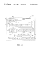
- FIG. 1 is an example schematic of a vehicle brake control system according to this invention
- FIG. 2 illustrates an example diagram of vehicle dynamics according to this invention
- FIG. 3 illustrates an example control according to this invention
- FIG. 4 illustrates an example vehicle slip angle observer according to this invention
- FIGS. 5-7 illustrate example gain functions for use with the example system described below;
- FIGS. 8-12 illustrate command flow diagrams of example control functions according to this invention.
- FIG. 13 illustrates an example vehicle reference model
- FIG. 14 illustrates another example vehicle reference model
- FIG. 15 illustrates an example tire force function
- the vehicle 10 shown includes a controllable brake system with controller 68 for controlling the brakes 20 , 22 , 24 and 26 of the vehicle wheels 12 , 14 , 16 and 18 , respectively.
- controller 68 for controlling the brakes 20 , 22 , 24 and 26 of the vehicle wheels 12 , 14 , 16 and 18 , respectively.
- Various inputs to the controller 68 include the wheel speed signals on lines 36 , 38 , 40 and 42 from wheel speed sensors 28 , 30 , 32 and 34 , the brake pedal switch signal on line 84 from brake pedal switch 82 , the brake pedal extended travel signal on line 83 from pedal travel sensor 85 (optional), the steering wheel angle signal on line 62 from sensor 61 indicating the angle of steering wheel 60 , the yaw rate signal on line 81 from yaw rate sensor 80 , the master cylinder pressure signal on line 96 from master cylinder pressure sensor 94 (optional) and the lateral acceleration signal on line 99 from lateral accelerometer 98 .
- the brake pedal travel sensor 85 is a switch mounted to the pedal that provides an output signal when the pedal has been depressed an extended amount indicating “hard” braking by the driver.
- the steering wheel position sensor 61 may be a digital sensor that provides output signals that increment a digital position signal within controller 68 with each degree or partial degree of movement of the steering wheel 60 in one direction and decrement the digital position signal with each degree or partial degree of movement in the opposite direction.
- the steering wheel sensor 61 may also include an analog sensor position output (i.e., from a rotary resistive device of a known type) that provides approximate steering wheel position information.
- the analog output can be used, for example, to determine whether the steering wheel is turned less than a preset limit, i.e., 90 degrees, at vehicle start-up.
- a method for determining the center position of the steering wheel position sensor is disclosed in pending U.S. patent application, Ser. No. 08/664,321, assigned to the assignee of this invention.
- the controller controls the braking of each wheel in anti-lock braking mode during certain braking maneuvers and in traction control mode during certain vehicle acceleration maneuvers to maintain tractive force of the drive wheels on the road surface.
- the anti-lock brake control and positive acceleration traction control are performed in a known manner except as modified herein.
- the controller 68 also actively controls the wheel brakes 20 , 22 (in a two channel system) or 20 , 22 , 24 and 26 (in a four channel system) responsive to the actual vehicle yaw rate and actual vehicle lateral acceleration as measured by sensors 80 and 98 , respectively, to minimize the difference between the actual vehicle yaw rate and a desired vehicle yaw rate and to minimize the difference between the actual vehicle slip angle and the desired vehicle slip angle.
- the base braking, antilock braking and traction control functions are known to those skilled in the art, only a general description thereof will be set forth herein.
- the controller monitors the wheel speed signals from sensors 28 , 30 , 32 and 34 and determines if one or more of the wheels is in or is about to be in an incipient lock-up condition, in which case anti-lock brake control mode for the one or more wheels is activated.
- the controller 68 determines and outputs commands to the actuators 52 , 54 , 56 and 58 corresponding to the wheels in anti-lock brake mode to modulate brake force to the wheels.
- the controller prevents the wheels from entering a lock-up condition while achieving effective brake control and steeribility in a manner known to those skilled in the art of anti-lock brake control.
- the controller 68 monitors the wheel speeds sensed by sensors 28 , 30 , 32 and 34 to determine if the wheels transferring motive force to the road surface are slipping or are about to slip. In such wheel conditions, the controller 68 sends commands to the actuators 52 - 58 corresponding to the wheels that are slipping or are about to slip to provide brake force to the wheels to reduce the slip. Such control is typically performed in conjunction with a parallel control in the engine or motor (and/or the transmission) controller to temporarily reduce the motive force output until wheel-to-road traction is reestablished.
- the brake actuators 52 - 58 are implemented as reciprocating piston actuators of a type known to those skilled in the art. Such actuators typically include a dc motor positionally controlling a reciprocating piston through a rotary-to-linear motion converter to increase and/or decrease hydraulic pressure in the wheel brakes.
- brake actuators 52 - 58 are implemented as solenoid valves for selectively coupling brakes 20 - 26 to a source of pressurized hydraulic fluid to increase brake pressure and for selectively coupling brakes 20 - 26 to a brake fluid reservoir to decrease brake pressure. Implementation of such solenoid valves is known to those skilled in the art.
- the rear brakes and/or the front brakes may be electric motor-driven brakes, in which case the actuator and brake functions are performed by the same unit.
- An example of a brake system including front hydraulic brakes and rear electric brakes in which all four brakes are controlled in a brake-by-wire method is set forth in U.S. Pat. No. 5,366,291, assigned to the assignee of this invention.
- the example system describe herein performs an active brake control of the two wheel brakes 20 and 22 or of the four wheel brakes 20 , 22 , 24 and 26 responsive to the steering wheel angle signal on line 62 , the yaw rate signal on line 81 , the vehicle speed as calculated responsive to the signals from the four wheel speed sensors, the lateral acceleration signal on line 99 and either the brake pedal extended travel sensor 85 or the master cylinder pressure sensor 94 .
- controller 68 determines a desired vehicle yaw rate and compares that desired yaw rate to the actual yaw rate sensed by sensor 80 .
- the controller 68 also determines a desired vehicle slip angle (defined below) and compares that desired vehicle slip angle to the actual vehicle slip angle as determined by an estimator or observer in the controller. If the yaw rate of the vehicle differs from the desired yaw rate by more than a yaw rate threshold that is dynamically determined, or if a desired corrective yaw moment determined responsive to yaw rate error and slip angle error is greater than a yaw moment threshold, controller 68 determines and outputs commands to actuators 52 , 54 , 56 and 58 to control the vehicle wheel brakes 20 , 22 , 24 and/or 26 to bring the vehicle yaw rate and slip angle into conformance with the desired yaw rate and slip angle. In a two channel system, only brakes 20 and. 22 are controlled via actuators 52 and 54 , respectively.
- controller 68 typically includes a microprocessor, ROM and RAM and appropriate input and output circuits of a known type for receiving the various input signals and for outputting the various control commands to the actuators 52 , 54 , 56 and 58 .
- the vehicle 10 has a longitudinal axis 201 oriented in what is referred to as the x direction or the forward direction of the vehicle.
- the vector denoted by reference 204 illustrates an example true velocity of the vehicle center of gravity, which has a direction oriented at an angle A, denoted by reference 202 , from the x axis or longitudinal axis 201 of the vehicle.
- the vector 204 has longitudinal (x axis) velocity component 208 and lateral velocity component 206 , which is parallel to what is referred to herein as the y axis.
- Reference 200 represents the vehicle center of gravity.
- the first is linear behavior during which the vehicle's yaw rate and slip angle have fixed relationships to steering wheel angle and vehicle forward velocity.
- a nonlinear operation of the vehicle is characterized by significant lateral movement of at least some of the vehicle tires with respect to the road surface.
- the vehicle's yaw rate 210 and slip angle 202 deviate from the fixed relationships to steering wheel angle and vehicle forward velocity that are characteristic of linear operation.
- This invention advantageously reduces the deviation of the vehicle's yaw rate 210 and slip angle 202 from desired yaw rates and slip angles during many nonlinear operating conditions of the vehicle.
- the control of the vehicle yaw rate and slip angle is achieved by the selective application of brake forces at the vehicle wheels 12 , 14 (in a two channel system) or 12 , 14 , 16 and 18 (in the four channel system) to induce yaw moments on the vehicle 10 countering the undesirable yaw movement detected of the vehicle 10 .
- These brake forces are illustrated graphically by references 212 . Additionally, during braking maneuvers a yaw moment may be introduced by decreasing brake forces at select wheels while maintaining or increasing the brake forces at other wheels. Decreases in brake forces are represented by references 214 .
- the example control shown includes the vehicle reference model 102 , block 104 representing the vehicle, estimators 120 and 122 for estimating the actual surface coefficient of adhesion and vehicle slip angle, respectively, yaw command and slip command control blocks 138 , 142 , output command block 154 and the brake actuators and wheel brakes represented by blocks 132 and 128 , respectively.
- time values denoted with a (k) represent present control-loop values and time values denoted by (k ⁇ n) represent the nth most recent control-loop values in a conventional manner.
- time value denotations i.e., (k)
- time value denotation is (k) unless otherwise specified.
- the vehicle reference model receives inputs from lines 112 , 62 and 121 representing the vehicle forward velocity, steering wheel angle and estimated surface coefficient of adhesion.
- the vehicle reference model uses the inputs to calculate desired vehicle slip angle, desired vehicle lateral velocity and desired vehicle yaw rate according to the following equations:
- v yd ( k ) (1 +a 11 * ⁇ t )* v yd ( k ⁇ 1)+ a 12 * ⁇ t* ⁇ du ( k ⁇ 1)+ b 1 * ⁇ t * ⁇ ( k ⁇ 1),
- ⁇ du ( k ) a 21 * ⁇ t*v yd ( k ⁇ 1)+(1 +a 22 * ⁇ t )* ⁇ du ( k ⁇ 1)+ b 2 * ⁇ t * ⁇ ( k ⁇ 1),
- ⁇ t is the sampling period (control loop time)
- a 11 ⁇ ( c f +c r )/( M*v x )
- a 12 ( ⁇ c f *a+c r *b )/( M*v x ) ⁇ v x ,
- a 21 ( ⁇ c f *a+c r *b )/( I zz *v x )
- a 22 ⁇ ( c f *a 2 +c r *b 2 )/( I zz *v x )
- ⁇ is the steering angle of the front wheels
- M is the total mass of the vehicle
- I zz is the moment of inertia of the vehicle about the yaw axis (passing through the center of gravity)
- a and b are distances from the center of gravity of the vehicle to the front and rear axles
- c f and c r are cornering stiffness coefficients of both tires of front and rear axles, respectively
- v x is the forward velocity of the vehicle
- v yd (k) is the desired lateral velocity of the vehicle at time k
- ⁇ du (k) is the desired yaw rate (unlimited) of the vehicle at time k
- ⁇ du is the unlimited desired slip angle of the vehicle.
- vehicle model is a preferred example and other vehicle models may be used as alternatives to determining the desired vehicle yaw rate and slip angles.
- the reference model 102 then limits the desired values of slip angle and yaw rate, where the maximum value of the desired slip angle is determined responsive to the estimated surface coefficient of adhesion ⁇ e determined at block 120 and output on line 121 .
- road to tire surface coefficient of adhesions are in the range of 0.2 to 1.0; 0.2 representing ice and 1.0 representing dry pavement.
- the maximum desired slip angle will be predetermined by the vehicle designer and may vary from vehicle type to vehicle type. In one example, the maximum desired slip angle on ice is 4° of slip angle and on a dry surface is 10°.
- ⁇ du * ⁇ 0.005 may be replaced by the condition v x ⁇ [c r *b*(a+b)/(M*a)] 1 ⁇ 2 since, when this condition is met, the signs of ⁇ du and ⁇ are the same.
- ⁇ d is not limited when the signs of slip angle and steering angle are the same, or equivalently when vehicle speed is below the value defined above.
- the desired yaw rate, ⁇ d is determined as ⁇ du , limited to plus and minus a predetermined parameter set, for example equal to 0.2 or 0.3 radians per second above the maximum yaw rate sustainable by the vehicle on a dry (high coefficient of adhesion) surface.
- the limit on the desired yaw rate may be speed dependent (e.g., the maximum magnitude for ⁇ d may be limited to a ymax /v x +0.3).
- the desired lateral acceleration, a yd is determined as:
- v yd ′ is the time derivative of v yd and may be computed as:
- the reference model 102 outputs the desired slip angle, ⁇ d , on line 106 , the desired yaw rate, ⁇ d , on line 108 and the desired lateral acceleration, a yd , on line 110 .
- the desired lateral acceleration on line 110 and the actual vehicle lateral acceleration on line 99 are provided to block 120 along with the measured vehicle yaw rate, ⁇ a , on line 81 , desired yaw rate, ⁇ d , steering angle, ⁇ , and vehicle speed, v x .
- Block 120 uses the actual and desired lateral accelerations and the actual and desired vehicle yaw rates to estimate a coefficient of adhesion between the road surface and the vehicle tires.
- the roll factor may be computed as:
- h is the height of the vehicle center of gravity and ⁇ is the total roll stiffness of the vehicle suspension.
- ⁇ is the total roll stiffness of the vehicle suspension.
- r fac ⁇ 0.9.
- the term measured lateral acceleration, a y refers to the lateral acceleration measured by the sensor 98 , multiplied by r fac and filtered through a low pass filter, e.g., a second order Butterworth filter having a cut off at 40 rad/s to reduce noise from the sensor signal.
- the estimation at block 120 first uses the steering angle and vehicle velocity to compute a value, ⁇ dss , referred to as the desired yaw rate at steady state, as follows:
- K u is the vehicle understeer coefficient, defined as:
- K u ( c r *b ⁇ c f *a )* M /( c f *c r *( a+b )).
- the value ⁇ dss differs from ⁇ d in that it does not account for the dynamic delay in the vehicle model that is included in the calculation of ⁇ d .
- the measured and desired lateral accelerations are passed through identical low pass filters to attenuate noise in the measured lateral acceleration signal.
- the desired lateral acceleration is then filtered through another low pass filter, for example, a standard second order Butterworth filter with a cut off frequency of 22 radians per second in order to reduce (or eliminate) the phase difference between the two signals.
- a value, a ydfl is determined by limiting the output of the Butterworth filter to +/ ⁇ a ymax , where a ymax is the maximum lateral acceleration that the vehicle can sustain on a dry surface.
- the magnitude of the lateral acceleration error, ⁇ ay is then determined according to:
- a y denotes the measured and filtered lateral acceleration.
- the value ⁇ a y is then filtered through a first order digital low pass filter, for example, with a cut off frequency of 2 radians per second, to yield the filtered lateral acceleration error, ⁇ a yf .
- a preliminary estimate of lateral surface coefficient of adhesion, ⁇ ay is determined according to:
- ⁇ temp is determined equal to ⁇ ay if all of the following conditions are met simultaneously:
- ⁇ d could be used instead of ⁇ dss , but ⁇ dss is preferable because the yaw rate error developed from
- a timer Ti ⁇ 0 ⁇ ⁇ if ⁇ ⁇ a ydfl * a y ⁇ - 0.1 ⁇ ⁇ or ⁇ ⁇ a y ⁇ ⁇ d * a y ⁇ - 0.1 Ti + ⁇ ⁇ ⁇ t , otherwise
- a yd is the desired (unfiltered) lateral acceleration
- ⁇ t is the loop time of the control algorithm
- 0.1 is an example constant to be determined as appropriate by the system designer.
- Condition (c) is met when Ti>0.3 seconds.
- ⁇ temp is set equal to ⁇ ay if the following three conditions are met simultaneously: (a) the vehicle velocity is small, for example, below 7 meters/second; (b) the signs of a ydfl and a y are the same and have been the same for at least a specified period of time, e.g., 0.3 seconds; and
- THRESH 1 , THRESH 2 and THRESH 3 are predetermined threshold values corresponding to lateral acceleration error and two yaw rate errors when the vehicle's behavior begins to deviate significantly from that of the linear model (i.e., the vehicle enters a non-linear range of operation).
- Example values for THRESH 1 , THRESH 2 and THRESH 3 are 1.2 m/s 2 , 0.10 rad/s and 0.14 rad/s, respectively. These threshold values may be made speed dependent.
- ⁇ temp is set equal to ⁇ ay , regardless of the above conditions, if the following condition is met:
- This above condition corrects the surface estimate when the magnitudes of measured lateral acceleration rises at least a given percentage (e.g., 5%) above the value that the present surface estimate would permit ( ⁇ temp *a ymax ).
- the reset value for ⁇ temp is 1.0 and ⁇ temp is reset to 1.0 when the following conditions are simultaneously met:
- a yd , a ydfl and a y have the same sign and have had the same sign for at least a specified time period, e.g., Ti>0.3 s.
- a value ⁇ new is determined according to:
- ⁇ new is then limited to no less than 0.07 and no greater than 1.0 to get ⁇ L , which is output on line 123 as the estimated surface coefficient of adhesion used in the slip angle estimation block 122 .
- the estimated surface coefficient of adhesion used for the control blocks 138 and 142 and used in the vehicle reference model 102 is determined by passing ⁇ new through a low pass filter, for example a second order Butterworth filter having a cut off frequency of 1.5 Hz.
- the filter output is then limited to no less than 0.2 and no greater than 1.0 to determine ⁇ e , the signal on line 121 .
- Block 122 estimates the side slip angle of the vehicle with a nonlinear dynamic observer.
- the observer 122 implements a vehicle model driven by two types of inputs: the steering input used by the driver to control the vehicle and the error signals, which are the differences between the measured (feedback) signals, lateral acceleration and yaw rate, and estimations predicted by the model.
- the feedback terms provide correction when the estimates deviate from actual measured values, preventing the tendency of the estimates to diverge with time because of inaccuracies between the model and the actual system and because of external disturbances.
- the observer 122 for estimating the vehicle slip angle relies on the estimated coefficient of adhesion determined at block 120 FIG. 3 .
- v y is the lateral velocity
- F yf and F yr are the lateral forces of the front and rear axles, respectively.
- These equations express the second law of dynamics for translation along lateral axis and rotation about the yaw axis.
- a critical step in the modeling process is computation of lateral forces of front and rear axles. These forces are relational to the slip angles of tires: the lateral forces initially rise almost linearly with the slip angle, then curve and saturate when the limit of adhesion is reached. The value of lateral forces at the limit is approximately proportional to the coefficient of adhesion. Also the value of slip angle at saturation is smaller on slippery (low coefficient of adhesion) surfaces than on high coefficient of adhesion surfaces.
- dv ye /dt ⁇ v x * ⁇ a +( F yfe +F yre )/ M+g 1 *( d ⁇ a /dt ⁇ ( a*F yfe ⁇ b*F yre )/ I zz ) ⁇ g 2 *( dv ye /dt ⁇ a y +v x * ⁇ a ) ⁇ g 3 *( a y ⁇ ( F yfe +F yre )/ M )
- F yfe and F yre used are estimates computed as described below, ⁇ a is the measured yaw rate and g 1 , g 2 and g 3 are the observer gains. If the estimates are perfect, then all expressions multiplied by the gains vanish; however, when a discrepancy between the estimated and actual values arise, the terms multiplied by the gains provide feedback to the vehicle model, reducing the errors between the actual and estimated values.
- the first two terms comprise an open loop dynamic model of the vehicle responsive to the measured vehicle speed and the measured yaw rate and the tire forces and the last three terms of the observer comprise a closed loop component in which g 1 is multiplied by a first error between the measured yaw rate and a predicted yaw rate, g 2 is multiplied by a second error between a previously estimated lateral velocity and a predicted lateral velocity and g 3 is multiplied by a third error between the measured lateral acceleration and apredicted lateral acceleration.
- a ym a y ⁇ g *sin ⁇ .
- the lateral acceleration error is low-pass filtered and the filter output is used as feedback in the observer.
- the observer becomes:
- dv ye /dt ⁇ v x * ⁇ a +( F yfe +F yre )/ M+g 1 *( d ⁇ a /dt ⁇ ( a*F yfe ⁇ b*F yre )/ I zz ) ⁇ g 2 *( dv ye /dt ⁇ a y +v x * ⁇ a ) ⁇ g 3 * ⁇ A y ⁇ g 4 * ⁇ A yf ,
- ⁇ A y is [a y ⁇ (F yfe +F yre )/M] and ⁇ A yf is the filtered version of ⁇ A y .
- dq/dt ⁇ (1 +g 2 )* v x * ⁇ a +((1 +g 3 )/ M ⁇ a*g 1 /I zz )* F yfe +((1 +g 3 )/ M+b*g 1 /I zz ) F yre +( g 2 ⁇ g 3 )* a y ⁇ g 4 * ⁇ A yf .
- Block 122 estimates the actual slip angle of the vehicle using the steering wheel angle signal on line 62 , the actual measured vehicle yaw rate on line 81 , the actual measured vehicle lateral acceleration on line 99 , estimated vehicle speed v x on line 61 and the estimated lateral surface coefficient of adhesion, ⁇ L , on line 123 .
- the slip angle estimation implements an iterative observer to determine the estimated vehicle slip angle, ⁇ e .
- the observer block 610 first estimates the side slip angles of front and rear axles using the following equations:
- ⁇ fe [v ye ( k ⁇ 1)+ a* ⁇ a ]/v x ⁇ and
- ⁇ re [v ye ( k ⁇ 1) ⁇ b* ⁇ a ]/v x ,
- v ye (k ⁇ 1) is the estimated lateral velocity on line 622 from the previous iteration of the observer
- ⁇ fe and ⁇ re are the front and rear axle side slip angles provided on line 608 .
- b cf is defined by:
- N f* M*b *( a ymax + ⁇ a )/( a+b )
- b cr is defined as:
- N r* M*a *( a ymax + ⁇ a )/( a+b ).
- the observer block 620 estimates a system state value, q(k), according to:
- ⁇ A y is defined as:
- ⁇ A yf is ⁇ A y passed through a first order digital low pass filter, for example, with a cut off frequency of 1 rad/s.
- Block 620 uses the state value, q(k), to determine estimates of lateral velocity, v ye , and slip angle, ⁇ e , as follows:
- v ye ( k ) ( q ( k )+ g 1 * ⁇ a )/(1 +g 2 ) and
- the gains g 1 , g 2 , g 3 and g 4 are tuning parameters preset by a system designer, typically through routine experimentation on a test vehicle, and may vary from implementation to implementation.
- the estimated slip angle determined by block 122 is output on line 124 .
- the control advantageously performs steps of estimating a front side slip angle of front vehicle wheels ( 610 ), estimating a rear side slip angle of rear vehicle wheels ( 610 ), estimating a first lateral force of the front wheels on a road surface responsive to the first side slip angle ( 611 ), estimating a second lateral force of the rear wheels on the road surface responsive to the second side slip angle ( 611 ), wherein the first lateral force estimation is responsive to a first function ( 616 ) for low values of the front side slip angle and responsive to a second function ( 614 ) for high values of the front side slip angle, wherein the second lateral force estimation is responsive to a third function ( 616 ) for low values of the rear side slip angle and responsive to a fourth function ( 614 ) for high values of the rear side slip angle, estimating a vehicle lateral velocity responsive to the first and second lateral force estimation and estimating a vehicle slip angle responsive to the vehicle lateral velocity and a vehicle forward velocity ( 620 ).
- the desired vehicle yaw rate, ⁇ d , and actual vehicle yaw rate, ⁇ a are summed at block 134 to provide a yaw rate error signal on line 136 , which is provided to the yaw rate command block 138 .
- the desired vehicle slip angle, ⁇ d , and the estimated vehicle slip angle, ⁇ e are summed at block 135 to provide a slip angle error signal on line 137 , which is provided to the slip angle command block 142 .
- Blocks 138 and 142 determine yaw rate and slip angle commands through a set of gains that are responsive to the vehicle speed signal on line 112 and to the estimated surface coefficient of adhesion, ⁇ e .
- the commands from blocks 138 and 142 are summed at block 146 , which provides the summation result, ⁇ M, on line 148 to block 154 .
- the magnitude of the gain increases as ⁇ e decreases and increases with vehicle speed until it saturates at a predetermined vehicle speed, for example, at 20 rm/s.
- the gains are represented graphically in FIG. 5 for three different surfaces, dry surface (reference 402 ) for which ⁇ 1.0, snow (reference 404 ) for which ⁇ 0.4 and ice (reference 406 ) for which ⁇ 0.2.
- the gain calculation may be implemented as an equation or using look-up tables providing the general shape shown in FIG. 5 .
- a factor f 1 is determined according to:
- k off and k mult are tuning parameters having example values of 1 and 0.5, respectively.
- the factor f 1 is then limited to a maximum value, for example, 4.
- f 1 increases in value when the vehicle slip angle approaches or exceeds the maximum allowable limit.
- This function allows f 1 to regulate the tradeoff between control of yaw rate and control of slip angle.
- ⁇ max which occurrences may also be characterized by a high slip angle error
- the factor f 1 increases the control influence or authority of the slip angle correction control as compared to the yaw rate correction control, thus providing an advantageous tradeoff between yaw rate and slip angle control.
- the increase in slip angle correction control authority is reflected in the proportional and derivative gains, k ⁇ p and k ⁇ d , respectively, for the slip command, determined using f 1 as follows:
- the yaw rate proportional and derivative gains, k ⁇ p and k ⁇ d are determined as follows:
- k′ ⁇ p is a preliminary gain that may either be constant or velocity dependent
- f 2 is a function of ⁇ e , determined according to
- the above equations illustrate that the yaw rate gains, k ⁇ p and k ⁇ d , are responsive to f 2 , which in turn is a function of the estimated surface coefficient of adhesion, ⁇ e .
- the factor f 2 decreases as ⁇ e decreases, thus f 2 increases the yaw rate control gains on high coefficient of adhesion surfaces (i.e., dry pavement) and decreases the yaw rate control gains on lower coefficient of adhesion surfaces (i.e., ice).
- f 2 operates to regulate between yaw rate control and slip angle control, increasing yaw rate control authority on high coefficient of adhesion road surfaces and decreasing yaw rate control authority on low coefficient of adhesion road surfaces.
- slip angle and yaw gains are used together with the actual and desired slip angles and actual and desired yaw rates to determine the desired corrective yaw moment, ⁇ M, for example, according to the following equation:
- ⁇ M k ⁇ p *( ⁇ d ⁇ e )+ k ⁇ d *( a y /v x ⁇ a )+ k ⁇ p *( ⁇ d ⁇ a )+ k ⁇ d *( ⁇ du ′ ⁇ a ′)
- ⁇ du ′ and ⁇ a ′ are the time derivatives of ⁇ du and ⁇ a , determined, for example, by passing each signal through a high pass filter.
- the value (a y /v x ⁇ a ) may be passed through a high pass “wash-out” filter, for example, having a transfer function of s/(s+1), in order to reduce the effects of sensor bias and banking of the road.
- the first two terms represent the slip angle command and the third and fourth terms represent the yaw rate command.
- the desired corrective yaw moment command, ⁇ M is output from block 146 to the output command block 154 .
- the first term of the above equation for ⁇ M may be ignored.
- the slip angle command is limited to control based on slip rate, since ⁇ ′ ⁇ a y /v x ⁇ a , This simplifies the algorithm since slip angle ⁇ does not have to be estimated and the desired value of slip angle is not used.
- the control gain k ⁇ d is computed as described above, i.e., it varies with vehicle speed and with the surface coefficient of adhesion but with the factor f 1 set equal to 1.0.
- the term (a y /v x ⁇ a ) may be replaced with a calculation of the slip angle error derivative ⁇ ′ determined as follows:
- ⁇ ′ ( ⁇ e ( k ) ⁇ du ( k ) ⁇ ( ⁇ e ( k ⁇ 1) ⁇ du ( k ⁇ 1)))/ ⁇ t,
- the first two terms of the equation for ⁇ M are set to zero when a magnitude of the sum of the first two terms otherwise is not above a predetermined value, defining a dead zone below which slip angle control is not triggered.
- the predetermined value defining the dead zone is set as desired by the system designer.
- the output command block 154 Before the output command block 154 makes use of the corrective yaw moment command, it must first determine whether the vehicle is in an oversteer or understeer condition. An understeer condition is established if the sign of ⁇ M and the steer angle ⁇ are the same. If ⁇ and ⁇ M have opposite signs, i.e., the product of ⁇ and ⁇ M is less than zero, or if either of the values is equal to zero, then the vehicle is designated as being in oversteer mode.
- a dead zone is introduced. That is, the vehicle is designated as being in oversteer when the product of ⁇ and ⁇ M is less than or equal to zero.
- the vehicle is designated as being in understeer when the product of ⁇ and ⁇ M is greater than THRESHD, where THRESHD is a dead zone threshold determined by the system designer.
- THRESHD is a dead zone threshold determined by the system designer.
- the corrective yaw force command, F is determined by dividing ⁇ M by half of the vehicle's track width, d.
- Applying the yaw force command to the actuators first involves distributing the force command to the various wheel brakes of the vehicle.
- the designation of inside and outside are with respect to the direction of turn. If the vehicle is being steered right, then the right front and right rear wheels are the inside wheels and the left front and rear wheels are the outside wheels. If the vehicle is being steered left, then the left front and rear wheels are the inside wheels and the right front and rear wheels are the outside wheels.
- the distribution of the commanded yaw force to the wheels described below is just one specific example of distribution, other examples are described in pending U.S. patent applications, Ser. No. 08/654,982 and Ser. No. 08/732,582, both assigned to the assignee of this invention.
- the distribution control is as follows. In an understeer condition, braking is applied in approximately equal distribution (the exact distribution may depend on a particular vehicle) to the inside rear and inside front wheels up to the point where ABS for the front and rear wheels is activated. At that point, the braking force applied to the wheels is not increased. If the rear wheel enters ABS control before the desired braking force is developed, the portion of the brake command sent to the inside rear wheel that the inside rear wheel was not able to achieve before entering ABS control is sent to the front inside wheel.
- ABS control In oversteer when the driver is not commanding braking, the brakes are applied to the outside front wheel only and braking force may be allowed to exceed the ABS limit. That is, the ABS control is overridden and the front wheel may be allowed to rise to higher slip levels and even to achieve a lock-up condition that the ABS control would normally prevent.
- the ABS control is overridden when the following conditions are simultaneously met: ABS control is active; the signs of estimated lateral force of the front axle, F yf , and steering angle are the same; the vehicle is and has been in oversteer condition for at least 0.1 seconds; and the total desired braking force of a particular wheel, F xd , is and has been for at least 0.1 seconds at least 1.5 times larger than the estimated braking force at the ABS limit, F xlim .
- F xd is determined by summing, for a particular wheel, the estimated brake force requested by the vehicle driver and the brake force resulting from the yaw force command.
- the forces F xlim for the front left and right wheels are computed as follows:
- N lf and N rf are the estimated normal tire forces on the left and right front wheels, respectively, defined by:
- N lf M*g*b /(2*( a+b ))+ K rllf *M*h*a y /trw ;
- N rf M*g*b /(2*( a+b )) ⁇ K rllf *M*h*a y /trw,
- trw is the average of the front and rear track widths
- h is the height of the vehicle center of gravity above the roll axis.
- the understeer condition is controlled as described above for the no driver-commanded braking mode, except that when both of the inside wheels (inside front wheel in a two channel system) reach an ABS limit before the total desired force is generated, then the brake command of the outside front wheel is reduced.
- the amount of brake command reduction to the outside front wheel is an amount necessary to transfer to the vehicle the difference between the yaw force command and the yaw force achieved by the two inside wheels before they went into ABS, except that the brake command reduction to the outside front wheel is limited so that at least a fixed percentage (e.g., 50%) of the driver commanded braking to the outside front wheel is maintained.
- the yaw force command is first applied to the outside front wheel brake, increasing brake force, possibly including to a point allowing the wheel to override the ABS limit. If the force achieved by the outside front wheel is not sufficient to produce the desired corrective yaw moment on the vehicle, braking of the inside rear wheel may be reduced by up to 50% of the driver commanded braking force for that wheel and if the force achieved by the outside front wheel and inside rear wheel (outside front only for a two channel system) is still not sufficient, then braking of the inside front wheel may be reduced by up to 50% of the driver commanded braking force for that wheel. When the ABS is overridden, the locking of the outside front wheel reduces the lateral force of the front wheel, which reduction of lateral force may be taken into account when calculating the corrective yaw moment.
- the force commands may be applied to the actuators as represented by line 158 and block 132 .
- this control it is necessary to reasonably estimate the amount of brake force applied at each particular wheel to determine the portion of the corrective yaw moment achieved by that wheel.
- hydraulic fluid pressure sensors in the individual wheel brake lines sense the amount of hydraulic pressure in the individual wheel brakes, and that sensed hydraulic pressure corresponds to a brake force measurement.
- the brake force may be determined by either position control or motor current feedback of the actuators, which position and/or motor current signals are taken as measurements of brake force at the individual wheels. Any other known method for measuring brake force at the individual wheels may be used and provided as feedback as represented by line 152 to the output command block 154 , for example to implement closed loop proportional derivative control of the actuators represented by block 132 .
- individual wheel speed control may be used to implement the brake force command in the vehicle wheel brakes.
- the desired yaw force, F may be converted into a wheel speed difference command (commanding a speed difference between left and right wheels) as follows:
- g v1 is a first gain value that varies linearly with vehicle speed and g v2 is a second gain value that varies non-linearly with the estimated surface coefficient of adhesion.
- An example graph of g 2 is shown in FIG. 6 .
- the desired wheel speed difference, ⁇ v xo is related directly to the slip angle errors and yaw rate errors without the intermediate step of calculating the desired yaw force. In that case:
- ⁇ v xo [k ⁇ p *( ⁇ d ⁇ e )+ k ⁇ d *( a y /v x ⁇ a )+ k ⁇ p *( ⁇ d ⁇ a )+ k ⁇ d *( ⁇ du ′ ⁇ a ′)]* v x ,
- control gains k ⁇ p , k ⁇ d , k ⁇ p and k ⁇ d are determined in the same manner as described above in connection with ⁇ M, except that k′ ⁇ p and k′ ⁇ p are determined as follows.
- the preliminary proportional gain k′ ⁇ p is constant or speed dependent.
- the preliminary slip angle gain k′ ⁇ p is determined (e.g., by using look-up tables) as a function of the estimated surface coefficient of adhesion, ⁇ e , and vehicle speed, v x .
- An example of relationships between k′ ⁇ p and vehicle speed on three different road surfaces are shown in FIG. 7 .
- Reference 420 illustrates the relationship for a dry road surface having ⁇ 1.0.
- Reference 422 illustrates the relationship for a snowy road surface having ⁇ 0.4
- reference 424 illustrates the relationship for an icy road surface having ⁇ 0.2.
- linear interpolation may be used.
- the wheel speed difference actually applied to the wheels, ⁇ v x is determined by ⁇ v xo and the kinematics of the turn, i.e.,
- trw is the track width (for the axle to which ⁇ v x is applied).
- the wheel speed difference command, ⁇ v x is distributed to the vehicle wheels as the yaw force command is distributed above.
- ⁇ v x is distributed to the vehicle wheels as the yaw force command is distributed above.
- half of ⁇ v x is applied to the inside rear wheel and half ⁇ v x is applied to the inside front wheel to reduce the inside rear wheel speed by 0.5* ⁇ v x less than its original speed prior to activation of the yaw control and to reduce the inside front wheel speed by 0.5* ⁇ v x less than its original speed prior to activation of the yaw control.
- the front wheel is slowed by an amount ⁇ v xf equal to ⁇ v x minus ⁇ v xr , where ⁇ v xr is the amount of inside rear wheel speed reduction achieved prior to the inside rear wheel entering ABS.
- the wheel speed control is similarly applied for the other braking distributions described above.
- closed loop wheel speed control may be used to transfer the desired corrective yaw force, F, capable of achieving the desired corrective yaw moment, ⁇ M, to the vehicle body.
- the commands determined at block 154 are only applied to the vehicle wheel brakes if the entry conditions for the active brake control are established and then are only applied until the exit conditions for active brake control are established.
- the estimated vehicle speed must be above a certain speed of entry, v min , which is typically low, for example 5 miles per hour. If this condition is satisfied, then the system becomes active when either yaw rate error exceeds a yaw rate error threshold or when the corrective yaw moment, ⁇ M, exceeds a corrective yaw moment threshold (or when wheel speed difference, ⁇ v x , exceeds a threshold).
- the yaw rate error test may be implemented by:
- ⁇ du ′ and ⁇ a ′ may be determined by passing ⁇ du and ⁇ a through high pass filters to time differentiate them, k e is a fixed constant and ⁇ thresh is determined in response to vehicle speed and steering wheel angle.
- ⁇ thresh is determined as follows:
- ⁇ thresh (9 ⁇ 0.036 *v x +1.3*( v x ⁇ )/(( a+b )+ K u *v x 2 ))/57.3,
- ⁇ thresh is expressed in (rad/s)
- v x is expressed in (m/s)
- ⁇ is expressed in (rad)
- a and b are expressed in (m)
- K u is the vehicle understeer coefficient.
- An exit condition is established if the total corrective yaw moment drops below a predetermined threshold value and remains below that value for a predetermined period of time or if the yaw rate error is below a predetermined yaw rate error threshold for a predetermined period of time. If either of these conditions exists, the output command block 154 is disabled and prevented from providing output commands to actuators 132 to establish corrective yaw moments on the vehicle. An exit condition is also established regardless of the above conditions if the vehicle speed drops below the speed of exit.
- an example main flow control routine illustrating example steps performed by a controller for achieving the desired yaw rate and slip angle control herein is illustrated.
- the system receives the inputs from the various system sensors and then at block 252 the vehicle determines the desired vehicle states as described above with reference to block 102 in FIG. 3 .
- Block 254 estimates the lateral coefficient of adhesion between the vehicle tires and the road surface as described above with reference to block 120 in FIG. 3 .
- the routine estimates the actual vehicle slip angle as described above with reference to block 122 in FIG. 3 .
- Block 258 determines the control gains for the slip and yaw rate commands as described above with reference to blocks 138 and 142 in FIG. 3 .
- Block 260 determines the corrective yaw moment command, ⁇ M, (or the desired wheel speed difference, ⁇ v x ) as described above with reference to block 154 in FIG. 3 and block 262 performs the enter/exit control determination. If the enter/exit control block 262 enables actuator control, then the actuator commands are determined at block 264 and output at block 266 to the various vehicle wheel brake actuators to achieve the desired corrective yaw moment on the vehicle body to minimize yaw rate error and vehicle slip angle error.
- Block 268 the vehicle model described above with reference to block 102 in FIG. 3 is used to determine v yd , ⁇ du , a yd , and ⁇ du .
- block 270 uses the estimated surface coefficient of adhesion and the steering wheel angle to determine ⁇ max , which is used with ⁇ du to determine ⁇ d at block 272 .
- Block 274 determines ⁇ d . All of the steps, 268 , 270 , 272 and 274 may be implemented as described above with reference to FIG. 3, block 102 .
- FIG. 10 illustrates the steps performed by block 258 in FIG. 8 for determining the control gains for the yaw rate command and slip angle command. More particularly, block 276 determines the preliminary proportional gain, k′ ⁇ p , as a function of v x and ⁇ e and block 278 determines the slip angle gain factor, f 1 , as a function of ⁇ e and ⁇ max . Then block 280 determines the slip angle gains as a function of k′ ⁇ p and f 1 . Block 282 determines the yaw rate proportional and derivative gains as a function of ⁇ e .
- the steps at blocks 276 , 278 , 280 and 282 may be implemented as described above with reference to blocks 138 and 142 in FIG. 3 .
- the forward vehicle velocity, v x is compared to a minimum velocity. If v x is not greater than the minimum vehicle velocity, the routine continues to block 320 where a flag is set, disabling the active brake control. If v x is greater than the minimum vehicle velocity, the routine continues to block 304 where it determines ⁇ thresh , as described above with reference to block 154 in FIG. 3 . If ⁇ err is greater than ⁇ thresh at block 306 , then the routine continues to block 310 .
- routine continues to block 308 where it compares the magnitude of the command ⁇ M to a threshold moment value. If ⁇ M does not have a magnitude greater than the threshold moment value, then the routine continues to block 312 . Otherwise, the routine continues to block 310 , where a flag is set enabling control of the brake system through the active brake control.
- the absolute values of ⁇ M( ⁇ v x ) and ⁇ err are compared to the exit threshold values. If either ⁇ M( ⁇ v x ) or ⁇ err is less than the exit threshold values, the routine continues to block 314 where a timer is incremented. Otherwise, at block 316 , the timer is reset. Block 318 compares the timer to a time out value. If the timer is greater than the time out value, the routine continues to block 320 where the flag is set disabling active brake control. Otherwise, the enter/exit control 262 is exited.
- First block 350 checks the understeer flag that, as described above with reference to block 154 in FIG. 3, indicates whether or not the vehicle is experiencing understeer or oversteer. If the understeer flag is set, the routine continues to block 352 where it compares the signs of the estimated lateral force at the rear axle, F yr , and the vehicle steering wheel angle. If they are different, for example, when the product F yr * ⁇ is less than zero, then the routine continues to block 356 where it sets the rear inside wheel force command F ir equal to 0.1*F. If at block 352 , F yr * ⁇ is not less than zero, then block 354 sets F ir equal to 0.5*F. This portion of the algorithm is used only for a four channel system.
- block 358 the routine continues to block 358 where it checks whether or not the inside rear wheel is in ABS mode. If so, block 360 determines the actual force applied by the inside rear wheel when it entered ABS, F ira , and block 364 determines the inside front wheel force command, F if , equal to F minus F ira . If, at block 358 , the rear wheel is not in ABS, then block 362 sets the inside front wheel command equal to F ⁇ F ir Then at block 366 , the routine checks whether or not braking is commanded by the vehicle driver, for example, by determining whether or not there is an output signal from the brake pedal switch or from the master cylinder pressure transducer. If not, the subroutine 264 exits.
- block 368 it checks whether or not the inside front and rear wheels are in ABS. If so, block 370 determines the actual force achieved by the inside front and rear wheels, F ifa and F ira , and then block 372 determines an outside front wheel brake force command, F of , equal to F ⁇ F ifa ⁇ F ira . Block 374 limits the command F of to a value between zero and half of the driver commanded brake force of the outside front wheel. From block 374 the routine is exited.
- routine If at block 350 the routine is not in understeer mode, then it proceeds to the oversteer steps at block 376 where the outside front wheel force command, F of , is set equal to F. Then block 378 checks whether or not braking is commanded. If not, block 380 sets a flag inhibiting activation of ABS control of the outside front wheel so that the outside front wheel is allowed to lock if the command, F of , so commands (the conditions under which the wheel is allowed to lock were specified above). From block 380 , the subroutine 264 is exited.
- the routine continues to block 382 where it checks whether the outside front wheel is in ABS. If not, the subroutine 264 is exited. If so, the subroutine continues to block 384 where it determines the actual braking force achieved by the outside front wheel, F ofa . The routine then moves to block 386 where an inside front wheel brake force command, F if , is determined equal to F ⁇ F ofa . If the outside front wheel is allowed to lock, then the effect of reduction in lateral force on the vehicle yaw moment is included in the above calculation; this yields:
- N of is the normal force on the outside front wheel determined as described above with reference to the lock-up conditions.
- the inside front wheel brake force command is then limited to half the driver-commanded braking to that wheel, as determined by the driver's brake request at block 388 .
- Block 390 determines the inside rear wheel brake force command as the difference between the commanded yaw force, F, and the yaw forces achieved by the outside and inside front wheels.
- the inside rear wheel brake force is limited to no greater than one half the driver commanded braking to the inside rear wheel.
- the front and rear inside wheel brake force commands, F if and F ir command reduction in the braking force at the front and rear inside wheels.
- the outside front wheel brake command, F of commands a reduction in the braking force applied to the outside front wheel.
- FIG. 13 illustrates another example vehicle reference model for determining desired yaw rate, ⁇ d , and desired slip angle, ⁇ d .
- the vehicle reference model 448 shown includes a single filter 450 , four look up tables (or equations) 452 , 454 , 462 and 464 and three simple equation functions 456 , 458 and 460 .
- the filter 450 implements the desired vehicle dynamics as represented by the damping ratio and natural frequency in a single filter whose output is used by the relatively simple calculations in blocks 456 , 458 and 460 to calculate both the desired slip angle and desired yaw rate.
- damping ratio and natural frequency may be expressed according to the system parameters as follows:
- ⁇ n ( a 11 *a 22 ⁇ a 12 *a 21 ) 1 ⁇ 2
- controller memory as look-up tables 462 and 464 responsive to the vehicle speed input v x or implemented as calculations.
- the filter 450 uses ⁇ n and ⁇ and the steering wheel angle input ⁇ , the filter 450 performs a filter function as follows:
- x 1 ′ ⁇ 2* ⁇ n *x 1 ⁇ n 2 *x 2
- Block 456 also receives the slip angle gain output of block 452 , which is a three dimensional look up table implementing the following function:
- V ydssgain ( ⁇ * v x /(( a+b )+ K u *v x 2 ))*( b ⁇ ( a*M*v x 2 )/(( a+b )* c r ).
- block 456 determines the desired lateral velocity v yd , according to:
- v yd b 1 *x 1 +V ydssgain * ⁇ n 2 *x 2 .
- Block 458 determines ⁇ du according to:
- ⁇ du tan ⁇ 1 ( v yd /v x ).
- Block 454 is a look up table determining the yaw rate gain according to the function:
- block 460 determines the desired yaw rate ⁇ d , according to:
- ⁇ d b 2 *x 1 +R gain * ⁇ n 2 *x 2 .
- Using the above approach allows the system designer to (a) select the damping ratio and natural frequency desired of the vehicle reference model, (b) define a single filter representing the selected damping ratio and natural frequency, (c) apply steering angle to the filter, (d) use the filter output with a predetermined slip angle gain function to determine desired vehicle slip angle and (e) use the filter output with a predetermined yaw gain function to determine the desired vehicle yaw rate.
- FIG. 14 illustrates another example vehicle reference model using a single filter.
- the vehicle reference model 558 includes the single filter 550 , look up tables 552 , 554 , 562 and 564 and functions 556 , 558 and 560 .
- the look up tables 562 , 564 and 554 are the same as look up tables 462 , 464 and 454 shown in FIG. 13 .
- the function blocks 558 and 560 are the same as function blocks 458 and 460 in FIG. 13 .
- Filter 550 is implemented in discrete form according to:
- x 1 ( k +1) c 1 *x 1 ( k )+ c 2 *x 2 ( k )+ c 3 *V ydss ( k +1), and
- x 2 ( k +1) x 2 ( k )+ T*x 1 ( k ),
- T is the sampling period
- V ydss ( k +1) ( ⁇ * v x ( k )/(( a+b )+ K u *v x ( k ) 2 ))*( b ⁇ ( a*M*v x ( k ) 2 )/(( a+b )* c r ).
- the output of filter 550 is used by block 556 to compute the desired lateral velocity, v yd (k+1), according to:
- v yd ( k +1) ⁇ n 2 *( x 2 ( k +1)+ x 1 ( k +1)/ z ),
- z a 12 *b 2 /b 1 ⁇ a 22 .
- the computation at block 556 is performed in a two-step process. First the value of z is computed and, if z equals zero, then z is limited to a predetermined minimum magnitude.
Abstract
Description


Claims (5)
Priority Applications (1)
| Application Number | Priority Date | Filing Date | Title |
|---|---|---|---|
| US08/925,247 US6547343B1 (en) | 1997-09-08 | 1997-09-08 | Brake system control |
Applications Claiming Priority (1)
| Application Number | Priority Date | Filing Date | Title |
|---|---|---|---|
| US08/925,247 US6547343B1 (en) | 1997-09-08 | 1997-09-08 | Brake system control |
Publications (1)
| Publication Number | Publication Date |
|---|---|
| US6547343B1 true US6547343B1 (en) | 2003-04-15 |
Family
ID=25451445
Family Applications (1)
| Application Number | Title | Priority Date | Filing Date |
|---|---|---|---|
| US08/925,247 Expired - Fee Related US6547343B1 (en) | 1997-09-08 | 1997-09-08 | Brake system control |
Country Status (1)
| Country | Link |
|---|---|
| US (1) | US6547343B1 (en) |
Cited By (64)
| Publication number | Priority date | Publication date | Assignee | Title |
|---|---|---|---|---|
| US20030149515A1 (en) * | 2000-12-30 | 2003-08-07 | Ulrich Hessmert | System and method for monitoring the vehicle dynamics of a motor vehicle |
| US20040102887A1 (en) * | 2002-11-26 | 2004-05-27 | Lin William C. | Method and apparatus for vehicle stability enhancement system |
| US20040154884A1 (en) * | 2002-06-20 | 2004-08-12 | Delphi Technologies, Inc. | Method and apparatus for control of a motor-driven brake actuator |
| US20040167700A1 (en) * | 2003-02-20 | 2004-08-26 | Delphi Technologies Inc. | Brake control method utilizing a controlled center differential |
| US20050012391A1 (en) * | 2003-07-17 | 2005-01-20 | Toshihisa Kato | Vehicle motion control apparatus |
| US20050057095A1 (en) * | 2003-09-17 | 2005-03-17 | Delphi Technologies Inc. | Control of brake-and steer-by-wire systems during brake failure |
| US20050082911A1 (en) * | 2002-02-08 | 2005-04-21 | Visteon Global Technologies, Inc. | Slip regulation algorithm for an automotive vehicle using a normal force estimate and a predetermined peak wheel slip value |
| US20050222731A1 (en) * | 2004-03-30 | 2005-10-06 | Ghoneim Youssef A | Method and apparatus for estimating steering behavior for integrated chassis control |
| GB2414815A (en) * | 2004-06-02 | 2005-12-07 | Ford Global Tech Llc | Determining lateral velocity and yaw rate of a vehicle |
| US20050278077A1 (en) * | 2004-06-09 | 2005-12-15 | Kwang-Keun Shin | Real-time vehicle dynamics estimation system |
| US20060064213A1 (en) * | 2001-11-21 | 2006-03-23 | Jianbo Lu | Enhanced system for yaw stability control system to include roll stability control function |
| US20070021896A1 (en) * | 2005-07-22 | 2007-01-25 | Delphi Technologies Inc. | Technique for determining motor vehicle slip angle while accounting for road banks |
| US20070067085A1 (en) * | 2005-09-19 | 2007-03-22 | Ford Global Technologies Llc | Integrated vehicle control system using dynamically determined vehicle conditions |
| EP1775188A1 (en) * | 2004-08-06 | 2007-04-18 | HONDA MOTOR CO., Ltd. | Control device for vehicle |
| WO2007074713A1 (en) | 2005-12-27 | 2007-07-05 | Honda Motor Co., Ltd. | Vehicle control device |
| US20080109134A1 (en) * | 2006-11-08 | 2008-05-08 | Delphi Technologies, Inc. | Methods, systems, and computer program products for calculating a torque overlay command in a steering control system |
| EP1950114A1 (en) * | 2005-12-27 | 2008-07-30 | Honda Motor Co., Ltd | Vehicle control device |
| EP1958839A1 (en) * | 2005-12-27 | 2008-08-20 | Honda Motor Co., Ltd | Vehicle control device |
| EP1967432A1 (en) * | 2005-12-27 | 2008-09-10 | Honda Motor Co., Ltd | Vehicle control device |
| US20090012669A1 (en) * | 2005-12-27 | 2009-01-08 | Honda Motor Co., Ltd. | Vehicle Control Device |
| DE102008032763A1 (en) | 2007-07-12 | 2009-02-05 | Magna Steyr Fahrzeugtechnik Ag & Co. Kg | Motor vehicle e.g. passenger car, driving dynamics controlling device, has actuator that is controlled according to result of comparison between measured yaw rate and stationary desired yaw rate, from control module |
| US20090132137A1 (en) * | 2005-12-27 | 2009-05-21 | Honda Motor Co., Ltd. | Controller of vehicle |
| DE102008032754A1 (en) | 2007-07-12 | 2009-07-16 | Magna Steyr Fahrzeugtechnik Ag & Co. Kg | Driving dynamics regulating device for vehicle, has actuator provided as part of all-wheel system, and/or motor- and/or drive management system, and/or hybrid system, and/or another controllable and/or regulatable subsystem |
| US20100025167A1 (en) * | 2008-07-31 | 2010-02-04 | Caterpillar Inc. | Braking system for an off-highway machine involving electric retarding integrated with service brakes |
| US20100036557A1 (en) * | 2005-11-09 | 2010-02-11 | Ford Global Technologies | System for dynamically determining axle loadings of a moving vehicle using integrated sensing system and its application in vehicle dynamics controls |
| US7668645B2 (en) | 2004-10-15 | 2010-02-23 | Ford Global Technologies | System and method for dynamically determining vehicle loading and vertical loading distance for use in a vehicle dynamic control system |
| US20100066277A1 (en) * | 2008-09-15 | 2010-03-18 | Caterpillar Inc. | Load demand and power generation balancing in direct series electric drive system |
| US20100066280A1 (en) * | 2008-09-15 | 2010-03-18 | Caterpillar Inc. | Electric drive retarding system and method |
| US20100070120A1 (en) * | 2008-09-15 | 2010-03-18 | Caterpillar Inc. | Engine load management for traction vehicles |
| US20100066316A1 (en) * | 2008-09-15 | 2010-03-18 | Caterpillar Inc. | Method and apparatus for detecting a short circuit in a DC link |
| US20100066400A1 (en) * | 2008-09-15 | 2010-03-18 | Caterpillar Inc. | Method and apparatus for determining the operating condition of generator rotating diodes |
| US20100065356A1 (en) * | 2008-09-15 | 2010-03-18 | Caterpillar Inc. | Electric powertrain for off-highway trucks |
| US20100065355A1 (en) * | 2008-09-15 | 2010-03-18 | Caterpillar Inc. | Cooling system for an electric drive machine and method |
| US20100066551A1 (en) * | 2008-09-15 | 2010-03-18 | Caterpillar Inc. | Method and apparatus for power generation failure diagnostics |
| US20100066294A1 (en) * | 2008-09-15 | 2010-03-18 | Caterpillar Inc. | Method and apparatus for detecting phase current imbalance in a power generator |
| US7715965B2 (en) | 2004-10-15 | 2010-05-11 | Ford Global Technologies | System and method for qualitatively determining vehicle loading conditions |
| EP2189343A1 (en) | 2008-11-25 | 2010-05-26 | Robert Bosch GmbH | Method for automatic trajectory correction |
| US20100131145A1 (en) * | 2008-11-24 | 2010-05-27 | Gm Global Technology Operations, Inc. | Vehicle lateral velocity and surface friction estimation using force tables |
| US7795825B2 (en) | 2008-09-15 | 2010-09-14 | Caterpillar Inc | Over-voltage and under-voltage management for electric drive system |
| US20110160971A1 (en) * | 2010-02-09 | 2011-06-30 | Dale Scott Crombez | Electro-Hydraulic Brake Brake-By-Wire System and Method |
| US20110160970A1 (en) * | 2010-02-09 | 2011-06-30 | Dale Scott Crombez | Electro-Hydraulic Brake-By-Wire System and Method |
| US20110160972A1 (en) * | 2010-02-09 | 2011-06-30 | Dale Scott Crombez | Electronic Brake Actuator Brake-By-Wire System and Method |
| US8054016B2 (en) | 2008-09-15 | 2011-11-08 | Caterpillar Inc. | Retarding energy calculator for an electric drive machine |
| US8121758B2 (en) | 2005-11-09 | 2012-02-21 | Ford Global Technologies | System for determining torque and tire forces using integrated sensing system |
| US8135528B2 (en) * | 2006-06-30 | 2012-03-13 | Honda Motor Co., Ltd. | Vehicle control device |
| US8281908B2 (en) | 2008-08-29 | 2012-10-09 | Caterpillar Inc. | Brake cooling fluid diverter for an off-highway machine |
| US8626368B2 (en) | 2010-09-07 | 2014-01-07 | Caterpillar Inc. | Electric drive power response management system and method |
| EP2684753A1 (en) * | 2012-07-11 | 2014-01-15 | KNORR-BREMSE Systeme für Nutzfahrzeuge GmbH | Method for estimating a vehicle's sideslip angle |
| US20140121928A1 (en) * | 2012-10-25 | 2014-05-01 | Denso Corporation | Deceleration control apparatus for motor vehicle |
| US20150105990A1 (en) * | 2012-06-21 | 2015-04-16 | Eaton Corporation | Predictive vehicle stability control method |
| US20150112568A1 (en) * | 2012-06-22 | 2015-04-23 | Advics Co., Ltd. | Vehicle braking force control apparatus |
| US9096201B2 (en) | 2011-03-18 | 2015-08-04 | Robert Bosch Gmbh | Yaw rate forecasting |
| US20150232104A1 (en) * | 2014-02-14 | 2015-08-20 | Denso Corporation | Vehicle-mounted apparatus for selecting preceding vehicle positioned in the travel path of the host vehicle of the apparatus |
| US9613466B1 (en) * | 2011-08-12 | 2017-04-04 | Brian Lee Bullock | Systems and methods for driver improvement |
| US20180229705A1 (en) * | 2015-07-27 | 2018-08-16 | Volvo Truck Corporation | Abs strategy for hybrid brake actuators |
| US10384672B1 (en) * | 2016-05-11 | 2019-08-20 | Apple Inc. | Vehicle stability control system |
| US10747223B1 (en) * | 2018-04-10 | 2020-08-18 | Aurora Innovation, Inc. | Redundant lateral velocity determination and use in secondary vehicle control systems |
| US10775804B1 (en) | 2018-04-10 | 2020-09-15 | Aurora Innovation, Inc. | Optical array sensor for use with autonomous vehicle control systems |
| CN112829761A (en) * | 2019-11-25 | 2021-05-25 | 固特异轮胎和橡胶公司 | Vehicle sideslip angle estimation system and method |
| US11142279B2 (en) * | 2018-01-24 | 2021-10-12 | Shimano Inc. | Brake control device and brake system |
| US11427197B2 (en) * | 2016-10-25 | 2022-08-30 | Toyota Jidosha Kabushiki Kaisha | Lane departure preventing device |
| US11427172B2 (en) * | 2016-10-19 | 2022-08-30 | Robert Bosch Gmbh | Lateral dynamic control for regenerative and friction brake blending |
| US20220348189A1 (en) * | 2021-04-28 | 2022-11-03 | Kubota Corporation | Work Vehicle |
| GB2614578A (en) * | 2022-01-05 | 2023-07-12 | Motional Ad Llc | Vehicle state estimation augmenting sensor data for vehicle control and autonomous driving |
Citations (25)
| Publication number | Priority date | Publication date | Assignee | Title |
|---|---|---|---|---|
| US4834205A (en) | 1987-02-03 | 1989-05-30 | Kabushiki Kaisha Toyota Chuo Kenkyusho | Apparatus for controlling steering of wheels of a vehicle |
| US5063514A (en) | 1990-06-19 | 1991-11-05 | General Motors Corporation | Abs yaw control |
| US5172961A (en) | 1990-07-05 | 1992-12-22 | Nissan Motor Co. Ltd. | Vehicle brake system including cornering characteristic control |
| DE4121954A1 (en) | 1991-07-03 | 1993-01-07 | Bosch Gmbh Robert | METHOD FOR OBTAINING THE YEAR SPEED AND / OR THE LATERAL SPEED |
| DE4200061A1 (en) | 1992-01-03 | 1993-07-08 | Bosch Gmbh Robert | METHOD FOR DETERMINING THE VEHICLE CROSS SPEED AND / OR THE SWIMMING ANGLE |
| US5229944A (en) | 1990-03-22 | 1993-07-20 | Yoshiki Yasuno | Braking force control apparatus |
| GB2263340A (en) | 1992-01-16 | 1993-07-21 | Steyr Daimler Puch Ag | Method for determining the dynamic safety margin of motor vehicles |
| EP0555360A1 (en) | 1990-10-29 | 1993-08-18 | Alza Corporation | Transdermal contraceptive formulations, methods and devices |
| US5275475A (en) | 1990-08-23 | 1994-01-04 | Robert Bosch Gmbh | Method for controlling vehicle dynamics |
| DE4223385A1 (en) | 1992-07-16 | 1994-01-20 | Bosch Gmbh Robert | Detecting reverse motion of motor vehicle for brake control system - measuring yaw rate, vehicle speed, wheel state and steering angle and using given equations to derive forward or reverse motion signals |
| GB2269571A (en) | 1992-08-13 | 1994-02-16 | Daimler Benz Ag | Process for determining quantities characterising vehicle travel behaviour. |
| DE4229504A1 (en) | 1992-09-04 | 1994-03-10 | Bosch Gmbh Robert | Vehicle road-curve stability regulation procedure - involves regulation of actual yaw velocity by comparison with required value as calculated from detected parameters |
| US5341297A (en) | 1991-07-13 | 1994-08-23 | Mercedes-Benz Ag | Apparatus and method for preventing instabilities in vehicle handling |
| GB2275312A (en) | 1993-02-19 | 1994-08-24 | Bosch Gmbh Robert | Vehicle movement dynamics control system |
| GB2275551A (en) | 1991-10-21 | 1994-08-31 | Intel Corp | Cross coupling mechanisms for microprocessor instructions using pipelining systems. |
| DE4311077A1 (en) | 1993-04-03 | 1994-10-06 | Bosch Gmbh Robert | Anti-lock control system |
| DE4314827A1 (en) | 1993-05-05 | 1994-11-10 | Porsche Ag | Method for determining the yaw velocity of a vehicle |
| US5366281A (en) | 1994-02-14 | 1994-11-22 | General Motors Corporation | Method of initializing a brake actuator |
| US5444621A (en) | 1991-06-10 | 1995-08-22 | Nippondenso Co., Ltd. | Suspension control system for controlling suspension of automotive vehicle based on wheel speed data |
| US5480219A (en) | 1992-12-23 | 1996-01-02 | Robert Bosch Gmbh | Control of vehicle side slip using yaw rate |
| US5641212A (en) * | 1994-12-14 | 1997-06-24 | Toyota Jidosha Kabushiki Kaisha | Dynamic behavior estimate system of automotive vehicle |
| US5676433A (en) * | 1995-10-25 | 1997-10-14 | Toyota Jidosha Kabushiki Kaisha | Device for estimating side slide velocity of vehicle compatible with rolling and cant |
| US5710705A (en) * | 1994-11-25 | 1998-01-20 | Itt Automotive Europe Gmbh | Method for determining an additional yawing moment based on side slip angle velocity |
| US5742918A (en) * | 1996-04-26 | 1998-04-21 | Ford Global Technologies, Inc. | Method and apparatus for dynamically compensating a lateral acceleration of a motor vehicle |
| US5813732A (en) * | 1995-10-06 | 1998-09-29 | Toyota Jidosha Kabushiki Kaisha | Stability control device of vehicle operative against spin and drift-out in harmony |
-
1997
- 1997-09-08 US US08/925,247 patent/US6547343B1/en not_active Expired - Fee Related
Patent Citations (27)
| Publication number | Priority date | Publication date | Assignee | Title |
|---|---|---|---|---|
| US4834205A (en) | 1987-02-03 | 1989-05-30 | Kabushiki Kaisha Toyota Chuo Kenkyusho | Apparatus for controlling steering of wheels of a vehicle |
| US5229944A (en) | 1990-03-22 | 1993-07-20 | Yoshiki Yasuno | Braking force control apparatus |
| US5063514A (en) | 1990-06-19 | 1991-11-05 | General Motors Corporation | Abs yaw control |
| US5172961A (en) | 1990-07-05 | 1992-12-22 | Nissan Motor Co. Ltd. | Vehicle brake system including cornering characteristic control |
| US5275475A (en) | 1990-08-23 | 1994-01-04 | Robert Bosch Gmbh | Method for controlling vehicle dynamics |
| EP0555360A1 (en) | 1990-10-29 | 1993-08-18 | Alza Corporation | Transdermal contraceptive formulations, methods and devices |
| US5444621A (en) | 1991-06-10 | 1995-08-22 | Nippondenso Co., Ltd. | Suspension control system for controlling suspension of automotive vehicle based on wheel speed data |
| US5311431A (en) | 1991-07-03 | 1994-05-10 | Robert Bosch Gmbh | Method of obtaining the yawing velocity and/or transverse velocity of a vehicle |
| DE4121954A1 (en) | 1991-07-03 | 1993-01-07 | Bosch Gmbh Robert | METHOD FOR OBTAINING THE YEAR SPEED AND / OR THE LATERAL SPEED |
| US5341297A (en) | 1991-07-13 | 1994-08-23 | Mercedes-Benz Ag | Apparatus and method for preventing instabilities in vehicle handling |
| GB2275551A (en) | 1991-10-21 | 1994-08-31 | Intel Corp | Cross coupling mechanisms for microprocessor instructions using pipelining systems. |
| DE4200061A1 (en) | 1992-01-03 | 1993-07-08 | Bosch Gmbh Robert | METHOD FOR DETERMINING THE VEHICLE CROSS SPEED AND / OR THE SWIMMING ANGLE |
| GB2263340A (en) | 1992-01-16 | 1993-07-21 | Steyr Daimler Puch Ag | Method for determining the dynamic safety margin of motor vehicles |
| DE4223385A1 (en) | 1992-07-16 | 1994-01-20 | Bosch Gmbh Robert | Detecting reverse motion of motor vehicle for brake control system - measuring yaw rate, vehicle speed, wheel state and steering angle and using given equations to derive forward or reverse motion signals |
| GB2269571A (en) | 1992-08-13 | 1994-02-16 | Daimler Benz Ag | Process for determining quantities characterising vehicle travel behaviour. |
| US5402342A (en) | 1992-09-04 | 1995-03-28 | Robert Bosch Gmbh | Method for controlling motor vehicle stability |
| DE4229504A1 (en) | 1992-09-04 | 1994-03-10 | Bosch Gmbh Robert | Vehicle road-curve stability regulation procedure - involves regulation of actual yaw velocity by comparison with required value as calculated from detected parameters |
| US5480219A (en) | 1992-12-23 | 1996-01-02 | Robert Bosch Gmbh | Control of vehicle side slip using yaw rate |
| GB2275312A (en) | 1993-02-19 | 1994-08-24 | Bosch Gmbh Robert | Vehicle movement dynamics control system |
| DE4311077A1 (en) | 1993-04-03 | 1994-10-06 | Bosch Gmbh Robert | Anti-lock control system |
| DE4314827A1 (en) | 1993-05-05 | 1994-11-10 | Porsche Ag | Method for determining the yaw velocity of a vehicle |
| US5366281A (en) | 1994-02-14 | 1994-11-22 | General Motors Corporation | Method of initializing a brake actuator |
| US5710705A (en) * | 1994-11-25 | 1998-01-20 | Itt Automotive Europe Gmbh | Method for determining an additional yawing moment based on side slip angle velocity |
| US5641212A (en) * | 1994-12-14 | 1997-06-24 | Toyota Jidosha Kabushiki Kaisha | Dynamic behavior estimate system of automotive vehicle |
| US5813732A (en) * | 1995-10-06 | 1998-09-29 | Toyota Jidosha Kabushiki Kaisha | Stability control device of vehicle operative against spin and drift-out in harmony |
| US5676433A (en) * | 1995-10-25 | 1997-10-14 | Toyota Jidosha Kabushiki Kaisha | Device for estimating side slide velocity of vehicle compatible with rolling and cant |
| US5742918A (en) * | 1996-04-26 | 1998-04-21 | Ford Global Technologies, Inc. | Method and apparatus for dynamically compensating a lateral acceleration of a motor vehicle |
Non-Patent Citations (16)
| Title |
|---|
| Active Stability Control; Junichi Kubokawa, Aisin Seiki Co., Ltd. Electronics & Brake Division; Abstract; Sep. 1995. |
| Consideration of Lateral and Longitudinal Vehicle Stability by Function Enhanced Brake and Stability Control System; Heinz Leffler; SAE #940832; Feb. 28-Mar. 3, 1994. |
| Control of Vehicle Dynamics: Automotive Engineering; pp. 87-93; May 1995. |
| Controlling Vehicle Stability; Christopher A. Sawyer, Automotive Industries, Jan. 1995. |
| Handling Control Systems For Your Car: Popular Electronics; Feb. 1995. |
| Improvement of Vehicle Maneuverability by Direct YAW Moment Control; Y. Shibahata, K. Shimada and T. Tomari; Society of Automotive Engineer of Japan, Inc.; pp. 464-481. |
| Let Magic Fingers Do The Driving: Wards Auto World; May 1995. |
| May The Cornering Force Be With You; Popular Mechanics; Dec. 1995, pp. 74-77. |
| Mercedes/Bosch ESP; Automotive Industries, April 1995. |
| Spin Control for Cars; Steven Ashley; Mechanical Engineering; pp. 66-68; June 1995. |
| Stable As She Goes: Don Sherman, Automotive Industries, May 1995. |
| Technoid: Intelligent Brakes Are on the Way; Car and Driver, Aug. 1994. |
| The Spin Doctors: Don Sherman, 12PS95. |
| Toyota Vehicle Stability Control System; Automotive Engineering, August 1995. |
| VDC, The Vehicle Dynamics Control System of Bosch: A. VanZanten, R. Erhardt and G. Pfaff; Robert Bosch GmbH; No. 950759, pp. 9-26. |
| Vehicle Dynamics Offers New Level of Safety: Machine Design, Sep. 1994. |
Cited By (140)
| Publication number | Priority date | Publication date | Assignee | Title |
|---|---|---|---|---|
| US20030149515A1 (en) * | 2000-12-30 | 2003-08-07 | Ulrich Hessmert | System and method for monitoring the vehicle dynamics of a motor vehicle |
| US20060064213A1 (en) * | 2001-11-21 | 2006-03-23 | Jianbo Lu | Enhanced system for yaw stability control system to include roll stability control function |
| US20050082911A1 (en) * | 2002-02-08 | 2005-04-21 | Visteon Global Technologies, Inc. | Slip regulation algorithm for an automotive vehicle using a normal force estimate and a predetermined peak wheel slip value |
| US20040154884A1 (en) * | 2002-06-20 | 2004-08-12 | Delphi Technologies, Inc. | Method and apparatus for control of a motor-driven brake actuator |
| US6913327B2 (en) | 2002-06-20 | 2005-07-05 | Delphi Technologies, Inc. | Method and apparatus for control of a motor-driven brake actuator |
| US20040102887A1 (en) * | 2002-11-26 | 2004-05-27 | Lin William C. | Method and apparatus for vehicle stability enhancement system |
| US6819998B2 (en) * | 2002-11-26 | 2004-11-16 | General Motors Corporation | Method and apparatus for vehicle stability enhancement system |
| US6895323B2 (en) | 2003-02-20 | 2005-05-17 | Delphi Technologies, Inc. | Brake control method utilizing a controlled center differential |
| US20040167700A1 (en) * | 2003-02-20 | 2004-08-26 | Delphi Technologies Inc. | Brake control method utilizing a controlled center differential |
| US7246864B2 (en) | 2003-07-17 | 2007-07-24 | Advics Co., Ltd. | Vehicle motion control apparatus |
| DE102004034402B4 (en) * | 2003-07-17 | 2011-01-20 | Advics Co., Ltd., Kariya-shi | Vehicle motion control device |
| US20050012391A1 (en) * | 2003-07-17 | 2005-01-20 | Toshihisa Kato | Vehicle motion control apparatus |
| US20050057095A1 (en) * | 2003-09-17 | 2005-03-17 | Delphi Technologies Inc. | Control of brake-and steer-by-wire systems during brake failure |
| US6923510B2 (en) | 2003-09-17 | 2005-08-02 | Delphi Technologies, Inc. | Control of brake-and steer-by-wire systems during brake failure |
| US20050222731A1 (en) * | 2004-03-30 | 2005-10-06 | Ghoneim Youssef A | Method and apparatus for estimating steering behavior for integrated chassis control |
| US7099759B2 (en) | 2004-03-30 | 2006-08-29 | General Motors Corporation | Method and apparatus for estimating steering behavior for integrated chassis control |
| GB2414815A (en) * | 2004-06-02 | 2005-12-07 | Ford Global Tech Llc | Determining lateral velocity and yaw rate of a vehicle |
| US7451032B2 (en) * | 2004-06-02 | 2008-11-11 | Ford Global Technologies, Llc | System and method for determining desired yaw rate and lateral velocity for use in a vehicle dynamic control system |
| GB2414815B (en) * | 2004-06-02 | 2008-06-11 | Ford Global Tech Llc | Determining lateral velocity and yaw rate of a vehicle |
| US7349778B2 (en) * | 2004-06-09 | 2008-03-25 | General Motors Corporation | Real-time vehicle dynamics estimation system |
| US7487021B2 (en) * | 2004-06-09 | 2009-02-03 | General Motors Corporation | Method for determining estimated vehicle dynamics parameters |
| US20070276564A1 (en) * | 2004-06-09 | 2007-11-29 | Gm Global Technology Operations, Inc. | Method for Determining Estimated Vehicle Dynamics Parameters |
| US20050278077A1 (en) * | 2004-06-09 | 2005-12-15 | Kwang-Keun Shin | Real-time vehicle dynamics estimation system |
| US7702442B2 (en) | 2004-08-06 | 2010-04-20 | Honda Motor Co., Ltd. | Control device for vehicle |
| EP1775188A4 (en) * | 2004-08-06 | 2009-10-21 | Honda Motor Co Ltd | Control device for vehicle |
| US20080133066A1 (en) * | 2004-08-06 | 2008-06-05 | Honda Motor Co., Ltd. | Control Device for Vehicle |
| EP1775188A1 (en) * | 2004-08-06 | 2007-04-18 | HONDA MOTOR CO., Ltd. | Control device for vehicle |
| US7877199B2 (en) | 2004-10-15 | 2011-01-25 | Ford Global Technologies | System and method for dynamically determining vehicle loading and vertical loading distance for use in a vehicle dynamic control system |
| US7715965B2 (en) | 2004-10-15 | 2010-05-11 | Ford Global Technologies | System and method for qualitatively determining vehicle loading conditions |
| US8050857B2 (en) | 2004-10-15 | 2011-11-01 | Ford Global Technologies | System and method for dynamically determining vehicle loading and vertical loading distance for use in a vehicle dynamic control system |
| US7668645B2 (en) | 2004-10-15 | 2010-02-23 | Ford Global Technologies | System and method for dynamically determining vehicle loading and vertical loading distance for use in a vehicle dynamic control system |
| US7877178B2 (en) | 2004-10-15 | 2011-01-25 | Ford Global Technologies | System and method for dynamically determining vehicle loading and vertical loading distance for use in a vehicle dynamic control system |
| US7899594B2 (en) | 2004-10-15 | 2011-03-01 | Ford Global Technologies | System and method for qualitatively determining vehicle loading conditions |
| US7877201B2 (en) | 2004-10-15 | 2011-01-25 | Ford Global Technologies | System and method for dynamically determining vehicle loading and vertical loading distance for use in a vehicle dynamic control system |
| US7877200B2 (en) | 2004-10-15 | 2011-01-25 | Ford Global Technologies | System and method for dynamically determining vehicle loading and vertical loading distance for use in a vehicle dynamic control system |
| US20070021896A1 (en) * | 2005-07-22 | 2007-01-25 | Delphi Technologies Inc. | Technique for determining motor vehicle slip angle while accounting for road banks |
| US7668637B2 (en) | 2005-07-22 | 2010-02-23 | O'dea Kevin Austin | Technique for determining motor vehicle slip angle while accounting for road banks |
| US8311706B2 (en) | 2005-09-19 | 2012-11-13 | Ford Global Technologies | Integrated vehicle control system using dynamically determined vehicle conditions |
| US8442720B2 (en) | 2005-09-19 | 2013-05-14 | Ford Global Technologies | Integrated vehicle control system using dynamically determined vehicle conditions |
| US8346452B2 (en) | 2005-09-19 | 2013-01-01 | Ford Global Technologies | Integrated vehicle control system using dynamically determined vehicle conditions |
| US8352143B2 (en) | 2005-09-19 | 2013-01-08 | Ford Global Technologies | Integrated vehicle control system using dynamically determined vehicle conditions |
| US20100017066A1 (en) * | 2005-09-19 | 2010-01-21 | Ford Global Technologies | Integrated vehicle control system using dynamically determined vehicle conditions |
| US20070067085A1 (en) * | 2005-09-19 | 2007-03-22 | Ford Global Technologies Llc | Integrated vehicle control system using dynamically determined vehicle conditions |
| US8005592B2 (en) | 2005-11-09 | 2011-08-23 | Ford Global Technologies | System for dynamically determining axle loadings of a moving vehicle using integrated sensing system and its application in vehicle dynamics controls |
| US8121758B2 (en) | 2005-11-09 | 2012-02-21 | Ford Global Technologies | System for determining torque and tire forces using integrated sensing system |
| US20100036557A1 (en) * | 2005-11-09 | 2010-02-11 | Ford Global Technologies | System for dynamically determining axle loadings of a moving vehicle using integrated sensing system and its application in vehicle dynamics controls |
| US20090118905A1 (en) * | 2005-12-27 | 2009-05-07 | Honda Motor Co., Ltd. | Vehicle control device |
| EP1958839A1 (en) * | 2005-12-27 | 2008-08-20 | Honda Motor Co., Ltd | Vehicle control device |
| WO2007074713A1 (en) | 2005-12-27 | 2007-07-05 | Honda Motor Co., Ltd. | Vehicle control device |
| EP2135787A1 (en) * | 2005-12-27 | 2009-12-23 | Honda Motor Co., Ltd. | Vehicle control device |
| EP2019013A3 (en) * | 2005-12-27 | 2009-10-21 | HONDA MOTOR CO., Ltd. | Vehicle control device |
| EP1967432A4 (en) * | 2005-12-27 | 2009-10-21 | Honda Motor Co Ltd | Vehicle control device |
| EP1950116A1 (en) * | 2005-12-27 | 2008-07-30 | Honda Motor Co., Ltd | Vehicle control device |
| EP1950114A1 (en) * | 2005-12-27 | 2008-07-30 | Honda Motor Co., Ltd | Vehicle control device |
| US8155852B2 (en) | 2005-12-27 | 2012-04-10 | Honda Motor Co., Ltd. | Vehicle control device |
| US20090319114A1 (en) * | 2005-12-27 | 2009-12-24 | Honda Motor Co., Ltd. | Vehicle control device |
| US8086383B2 (en) | 2005-12-27 | 2011-12-27 | Honda Motor Co., Ltd. | Vehicle control device |
| US8050822B2 (en) | 2005-12-27 | 2011-11-01 | Honda Motor Co., Ltd. | Controller of vehicle |
| EP1967432A1 (en) * | 2005-12-27 | 2008-09-10 | Honda Motor Co., Ltd | Vehicle control device |
| US8027775B2 (en) | 2005-12-27 | 2011-09-27 | Honda Motor Co., Ltd. | Vehicle control device |
| US8024091B2 (en) | 2005-12-27 | 2011-09-20 | Honda Motor Co., Ltd. | Vehicle control device |
| EP1950114A4 (en) * | 2005-12-27 | 2009-10-21 | Honda Motor Co Ltd | Vehicle control device |
| US20090187302A1 (en) * | 2005-12-27 | 2009-07-23 | Honda Motor Co., Ltd. | Vehicle control device |
| EP1950116A4 (en) * | 2005-12-27 | 2008-11-12 | Honda Motor Co Ltd | Vehicle control device |
| CN101341058B (en) * | 2005-12-27 | 2011-07-27 | 本田技研工业株式会社 | Controller of vehicle |
| US7987029B2 (en) | 2005-12-27 | 2011-07-26 | Honda Motor Co., Ltd. | Vehicle control device |
| CN101341057B (en) * | 2005-12-27 | 2011-07-13 | 本田技研工业株式会社 | Vehicle control device |
| CN101193785B (en) * | 2005-12-27 | 2011-07-06 | 本田技研工业株式会社 | Vehicle control device |
| CN101331046B (en) * | 2005-12-27 | 2011-06-15 | 本田技研工业株式会社 | Vehicle control device |
| US20090171526A1 (en) * | 2005-12-27 | 2009-07-02 | Honda Motor Co., Ltd. | Vehicle Control Device |
| US20090132137A1 (en) * | 2005-12-27 | 2009-05-21 | Honda Motor Co., Ltd. | Controller of vehicle |
| CN101331045B (en) * | 2005-12-27 | 2011-06-15 | 本田技研工业株式会社 | Vehicle control device |
| US20090012669A1 (en) * | 2005-12-27 | 2009-01-08 | Honda Motor Co., Ltd. | Vehicle Control Device |
| EP1958839A4 (en) * | 2005-12-27 | 2008-11-19 | Honda Motor Co Ltd | Vehicle control device |
| US8135528B2 (en) * | 2006-06-30 | 2012-03-13 | Honda Motor Co., Ltd. | Vehicle control device |
| CN101454190B (en) * | 2006-06-30 | 2012-05-09 | 本田技研工业株式会社 | Vehicle control device |
| US20080109134A1 (en) * | 2006-11-08 | 2008-05-08 | Delphi Technologies, Inc. | Methods, systems, and computer program products for calculating a torque overlay command in a steering control system |
| US7835836B2 (en) | 2006-11-08 | 2010-11-16 | Gm Global Technology Operations, Inc. | Methods, systems, and computer program products for calculating a torque overlay command in a steering control system |
| DE102008032763A1 (en) | 2007-07-12 | 2009-02-05 | Magna Steyr Fahrzeugtechnik Ag & Co. Kg | Motor vehicle e.g. passenger car, driving dynamics controlling device, has actuator that is controlled according to result of comparison between measured yaw rate and stationary desired yaw rate, from control module |
| DE102008032754A1 (en) | 2007-07-12 | 2009-07-16 | Magna Steyr Fahrzeugtechnik Ag & Co. Kg | Driving dynamics regulating device for vehicle, has actuator provided as part of all-wheel system, and/or motor- and/or drive management system, and/or hybrid system, and/or another controllable and/or regulatable subsystem |
| US20100025167A1 (en) * | 2008-07-31 | 2010-02-04 | Caterpillar Inc. | Braking system for an off-highway machine involving electric retarding integrated with service brakes |
| US8490760B2 (en) | 2008-08-29 | 2013-07-23 | Caterpillar Inc. | Brake cooling fluid diverter for an off-highway machine |
| US8281908B2 (en) | 2008-08-29 | 2012-10-09 | Caterpillar Inc. | Brake cooling fluid diverter for an off-highway machine |
| US8410739B2 (en) | 2008-09-15 | 2013-04-02 | Caterpillar Inc. | Method and apparatus for determining the operating condition of generator rotating diodes |
| US7795825B2 (en) | 2008-09-15 | 2010-09-14 | Caterpillar Inc | Over-voltage and under-voltage management for electric drive system |
| US7996163B2 (en) | 2008-09-15 | 2011-08-09 | Caterpillar Inc. | Method and apparatus for detecting a short circuit in a DC link |
| US7956762B2 (en) | 2008-09-15 | 2011-06-07 | Caterpillar Inc. | Method and apparatus for power generation failure diagnostics |
| US20100066294A1 (en) * | 2008-09-15 | 2010-03-18 | Caterpillar Inc. | Method and apparatus for detecting phase current imbalance in a power generator |
| US20100066551A1 (en) * | 2008-09-15 | 2010-03-18 | Caterpillar Inc. | Method and apparatus for power generation failure diagnostics |
| US20100065355A1 (en) * | 2008-09-15 | 2010-03-18 | Caterpillar Inc. | Cooling system for an electric drive machine and method |
| US20100065356A1 (en) * | 2008-09-15 | 2010-03-18 | Caterpillar Inc. | Electric powertrain for off-highway trucks |
| US8054016B2 (en) | 2008-09-15 | 2011-11-08 | Caterpillar Inc. | Retarding energy calculator for an electric drive machine |
| US20100066400A1 (en) * | 2008-09-15 | 2010-03-18 | Caterpillar Inc. | Method and apparatus for determining the operating condition of generator rotating diodes |
| US8428805B2 (en) | 2008-09-15 | 2013-04-23 | Caterpillar Inc. | Engine load management for traction vehicles |
| US20100066316A1 (en) * | 2008-09-15 | 2010-03-18 | Caterpillar Inc. | Method and apparatus for detecting a short circuit in a DC link |
| US7918296B2 (en) | 2008-09-15 | 2011-04-05 | Caterpillar Inc. | Cooling system for an electric drive machine and method |
| US8140206B2 (en) | 2008-09-15 | 2012-03-20 | Caterpillar Inc. | Engine load management for traction vehicles |
| US20100070120A1 (en) * | 2008-09-15 | 2010-03-18 | Caterpillar Inc. | Engine load management for traction vehicles |
| US9063202B2 (en) | 2008-09-15 | 2015-06-23 | Caterpillar Inc. | Method and apparatus for detecting phase current imbalance in a power generator |
| US8253357B2 (en) | 2008-09-15 | 2012-08-28 | Caterpillar Inc. | Load demand and power generation balancing in direct series electric drive system |
| US20100066277A1 (en) * | 2008-09-15 | 2010-03-18 | Caterpillar Inc. | Load demand and power generation balancing in direct series electric drive system |
| US20100066280A1 (en) * | 2008-09-15 | 2010-03-18 | Caterpillar Inc. | Electric drive retarding system and method |
| US8324846B2 (en) | 2008-09-15 | 2012-12-04 | Caterpillar Inc. | Electric drive retarding system and method |
| US8086367B2 (en) * | 2008-11-24 | 2011-12-27 | GM Global Technology Operations LLC | Vehicle lateral velocity and surface friction estimation using force tables |
| US20100131145A1 (en) * | 2008-11-24 | 2010-05-27 | Gm Global Technology Operations, Inc. | Vehicle lateral velocity and surface friction estimation using force tables |
| FR2938809A1 (en) * | 2008-11-25 | 2010-05-28 | Bosch Gmbh Robert | AUTOMATIC PATH CORRECTION METHOD. |
| EP2189343A1 (en) | 2008-11-25 | 2010-05-26 | Robert Bosch GmbH | Method for automatic trajectory correction |
| US20110160972A1 (en) * | 2010-02-09 | 2011-06-30 | Dale Scott Crombez | Electronic Brake Actuator Brake-By-Wire System and Method |
| US20110160970A1 (en) * | 2010-02-09 | 2011-06-30 | Dale Scott Crombez | Electro-Hydraulic Brake-By-Wire System and Method |
| US20110160971A1 (en) * | 2010-02-09 | 2011-06-30 | Dale Scott Crombez | Electro-Hydraulic Brake Brake-By-Wire System and Method |
| US9002608B2 (en) | 2010-02-09 | 2015-04-07 | Ford Global Technologies, Llc | Electro-hydraulic brake-by-wire system and method |
| US8626368B2 (en) | 2010-09-07 | 2014-01-07 | Caterpillar Inc. | Electric drive power response management system and method |
| US9096201B2 (en) | 2011-03-18 | 2015-08-04 | Robert Bosch Gmbh | Yaw rate forecasting |
| US9613466B1 (en) * | 2011-08-12 | 2017-04-04 | Brian Lee Bullock | Systems and methods for driver improvement |
| US20150105990A1 (en) * | 2012-06-21 | 2015-04-16 | Eaton Corporation | Predictive vehicle stability control method |
| US9248833B2 (en) * | 2012-06-21 | 2016-02-02 | Eaton Corporation | Predictive vehicle stability control method |
| US20150112568A1 (en) * | 2012-06-22 | 2015-04-23 | Advics Co., Ltd. | Vehicle braking force control apparatus |
| US9393939B2 (en) * | 2012-06-22 | 2016-07-19 | Advics Co., Ltd. | Vehicle braking force control apparatus |
| EP2684753A1 (en) * | 2012-07-11 | 2014-01-15 | KNORR-BREMSE Systeme für Nutzfahrzeuge GmbH | Method for estimating a vehicle's sideslip angle |
| US20140121928A1 (en) * | 2012-10-25 | 2014-05-01 | Denso Corporation | Deceleration control apparatus for motor vehicle |
| US9434363B2 (en) * | 2012-10-25 | 2016-09-06 | Denso Corporation | Deceleration control apparatus for motor vehicle |
| US20150232104A1 (en) * | 2014-02-14 | 2015-08-20 | Denso Corporation | Vehicle-mounted apparatus for selecting preceding vehicle positioned in the travel path of the host vehicle of the apparatus |
| US9421980B2 (en) * | 2014-02-14 | 2016-08-23 | Denso Corporation | Vehicle-mounted apparatus for selecting preceding vehicle positioned in the travel path of the host vehicle of the apparatus |
| US20180229705A1 (en) * | 2015-07-27 | 2018-08-16 | Volvo Truck Corporation | Abs strategy for hybrid brake actuators |
| US10766472B2 (en) * | 2015-07-27 | 2020-09-08 | Volvo Truck Corporation | ABS strategy for hybrid brake actuators |
| US10384672B1 (en) * | 2016-05-11 | 2019-08-20 | Apple Inc. | Vehicle stability control system |
| US11427172B2 (en) * | 2016-10-19 | 2022-08-30 | Robert Bosch Gmbh | Lateral dynamic control for regenerative and friction brake blending |
| US11427197B2 (en) * | 2016-10-25 | 2022-08-30 | Toyota Jidosha Kabushiki Kaisha | Lane departure preventing device |
| US11142279B2 (en) * | 2018-01-24 | 2021-10-12 | Shimano Inc. | Brake control device and brake system |
| TWI768164B (en) * | 2018-01-24 | 2022-06-21 | 日商島野股份有限公司 | Brake control device and braking system |
| US11353867B1 (en) * | 2018-04-10 | 2022-06-07 | Aurora Operations, Inc. | Redundant lateral velocity determination and use in secondary vehicle control systems |
| US10775804B1 (en) | 2018-04-10 | 2020-09-15 | Aurora Innovation, Inc. | Optical array sensor for use with autonomous vehicle control systems |
| US10747223B1 (en) * | 2018-04-10 | 2020-08-18 | Aurora Innovation, Inc. | Redundant lateral velocity determination and use in secondary vehicle control systems |
| US20220308580A1 (en) * | 2018-04-10 | 2022-09-29 | Aurora Operations, Inc. | Redundant Lateral Velocity Determination and Use in Secondary Vehicle Control Systems |
| US11874660B2 (en) * | 2018-04-10 | 2024-01-16 | Aurora Operations, Inc. | Redundant lateral velocity determination and use in secondary vehicle control systems |
| CN112829761A (en) * | 2019-11-25 | 2021-05-25 | 固特异轮胎和橡胶公司 | Vehicle sideslip angle estimation system and method |
| EP3825191A1 (en) * | 2019-11-25 | 2021-05-26 | The Goodyear Tire & Rubber Company | Vehicle sideslip angle estimation system and method |
| US11702084B2 (en) | 2019-11-25 | 2023-07-18 | The Goodyear Tire & Rubber Company | Vehicle sideslip angle estimation system and method |
| US20220348189A1 (en) * | 2021-04-28 | 2022-11-03 | Kubota Corporation | Work Vehicle |
| GB2614578A (en) * | 2022-01-05 | 2023-07-12 | Motional Ad Llc | Vehicle state estimation augmenting sensor data for vehicle control and autonomous driving |
Similar Documents
| Publication | Publication Date | Title |
|---|---|---|
| US6547343B1 (en) | Brake system control | |
| US6122584A (en) | Brake system control | |
| US6125319A (en) | Brake system control method responsive to measured vehicle acceleration | |
| US6453226B1 (en) | Integrated control of active tire steer and brakes | |
| US5931887A (en) | Brake control method based on a linear transfer function reference model | |
| US6549842B1 (en) | Method and apparatus for determining an individual wheel surface coefficient of adhesion | |
| US6195606B1 (en) | Vehicle active brake control with bank angle compensation | |
| US5941919A (en) | Chassis control system | |
| US5746486A (en) | Brake control system | |
| JP3426000B2 (en) | Control method of vehicle stability in curve running | |
| US7308351B2 (en) | Method for coordinating a vehicle dynamics control system with an active normal force adjustment system | |
| US5667286A (en) | Brake control system | |
| US6334656B1 (en) | Method and system for controlling the yaw moment of a vehicle | |
| EP1627779B1 (en) | Tire grip performance estimation device and method and running state control method | |
| US6236926B1 (en) | Vehicle behavior control device | |
| US6662898B1 (en) | Tire side slip angle control for an automotive vehicle using steering actuators | |
| US7191047B2 (en) | Motor vehicle control using a dynamic feedforward approach | |
| US20020042671A1 (en) | Motor vehicle with supplemental rear steering having open and closed loop modes | |
| US6112147A (en) | Vehicle yaw rate control with bank angle compensation | |
| US6212460B1 (en) | Brake control system | |
| EP0982206B1 (en) | Method of estimating vehicle yaw rate | |
| Gowda et al. | Slip ratio control of anti-lock braking system with bang-bang controller | |
| US6466857B1 (en) | Drive wheel traction control during vehicle stability enhancement events | |
| US7502675B2 (en) | Feedforward control of motor vehicle roll angle | |
| US6588859B2 (en) | System and method for vehicle stability enhancement control with surface estimate |
Legal Events
| Date | Code | Title | Description |
|---|---|---|---|
| AS | Assignment |
Owner name: GENERAL MOTORS CORPORATION, MICHIGAN Free format text: ASSIGNMENT OF ASSIGNORS INTEREST;ASSIGNOR:HAC, ALEKSANDER BOGUSLAW;REEL/FRAME:008703/0991 Effective date: 19970828 |
|
| FPAY | Fee payment |
Year of fee payment: 4 |
|
| AS | Assignment |
Owner name: GM GLOBAL TECHNOLOGY OPERATIONS, INC., MICHIGAN Free format text: ASSIGNMENT OF ASSIGNORS INTEREST;ASSIGNOR:GENERAL MOTORS CORPORATION;REEL/FRAME:022092/0886 Effective date: 20050119 |
|
| AS | Assignment |
Owner name: UNITED STATES DEPARTMENT OF THE TREASURY, DISTRICT Free format text: SECURITY AGREEMENT;ASSIGNOR:GM GLOBAL TECHNOLOGY OPERATIONS, INC.;REEL/FRAME:022201/0501 Effective date: 20081231 |
|
| AS | Assignment |
Owner name: CITICORP USA, INC. AS AGENT FOR HEDGE PRIORITY SEC Free format text: SECURITY AGREEMENT;ASSIGNOR:GM GLOBAL TECHNOLOGY OPERATIONS, INC.;REEL/FRAME:022556/0013 Effective date: 20090409 Owner name: CITICORP USA, INC. AS AGENT FOR BANK PRIORITY SECU Free format text: SECURITY AGREEMENT;ASSIGNOR:GM GLOBAL TECHNOLOGY OPERATIONS, INC.;REEL/FRAME:022556/0013 Effective date: 20090409 |
|
| AS | Assignment |
Owner name: GM GLOBAL TECHNOLOGY OPERATIONS, INC., MICHIGAN Free format text: RELEASE BY SECURED PARTY;ASSIGNOR:UNITED STATES DEPARTMENT OF THE TREASURY;REEL/FRAME:023238/0015 Effective date: 20090709 |
|
| XAS | Not any more in us assignment database |
Free format text: RELEASE BY SECURED PARTY;ASSIGNOR:UNITED STATES DEPARTMENT OF THE TREASURY;REEL/FRAME:023124/0383 |
|
| AS | Assignment |
Owner name: GM GLOBAL TECHNOLOGY OPERATIONS, INC., MICHIGAN Free format text: RELEASE BY SECURED PARTY;ASSIGNORS:CITICORP USA, INC. AS AGENT FOR BANK PRIORITY SECURED PARTIES;CITICORP USA, INC. AS AGENT FOR HEDGE PRIORITY SECURED PARTIES;REEL/FRAME:023127/0326 Effective date: 20090814 |
|
| AS | Assignment |
Owner name: UNITED STATES DEPARTMENT OF THE TREASURY, DISTRICT Free format text: SECURITY AGREEMENT;ASSIGNOR:GM GLOBAL TECHNOLOGY OPERATIONS, INC.;REEL/FRAME:023155/0922 Effective date: 20090710 |
|
| AS | Assignment |
Owner name: UAW RETIREE MEDICAL BENEFITS TRUST, MICHIGAN Free format text: SECURITY AGREEMENT;ASSIGNOR:GM GLOBAL TECHNOLOGY OPERATIONS, INC.;REEL/FRAME:023161/0864 Effective date: 20090710 |
|
| REMI | Maintenance fee reminder mailed | ||
| LAPS | Lapse for failure to pay maintenance fees | ||
| STCH | Information on status: patent discontinuation |
Free format text: PATENT EXPIRED DUE TO NONPAYMENT OF MAINTENANCE FEES UNDER 37 CFR 1.362 |
|
| FP | Lapsed due to failure to pay maintenance fee |
Effective date: 20110415 |