US6519476B1 - Radio communication system wherein insertion of an attachable external storage medium causes the mobile to interact with the system - Google Patents
Radio communication system wherein insertion of an attachable external storage medium causes the mobile to interact with the system Download PDFInfo
- Publication number
- US6519476B1 US6519476B1 US09/126,468 US12646898A US6519476B1 US 6519476 B1 US6519476 B1 US 6519476B1 US 12646898 A US12646898 A US 12646898A US 6519476 B1 US6519476 B1 US 6519476B1
- Authority
- US
- United States
- Prior art keywords
- communication
- radio
- storage medium
- external storage
- monitor
- Prior art date
- Legal status (The legal status is an assumption and is not a legal conclusion. Google has not performed a legal analysis and makes no representation as to the accuracy of the status listed.)
- Expired - Fee Related
Links
- 238000004891 communication Methods 0.000 title claims abstract description 126
- 238000003860 storage Methods 0.000 title claims description 14
- 238000003780 insertion Methods 0.000 title claims 6
- 230000037431 insertion Effects 0.000 title claims 6
- 238000012544 monitoring process Methods 0.000 claims description 5
- 230000005540 biological transmission Effects 0.000 abstract description 3
- 238000010586 diagram Methods 0.000 description 12
- 238000000034 method Methods 0.000 description 10
- 238000012545 processing Methods 0.000 description 6
- 238000006243 chemical reaction Methods 0.000 description 4
- 238000012790 confirmation Methods 0.000 description 3
- 230000003321 amplification Effects 0.000 description 2
- 239000000969 carrier Substances 0.000 description 2
- 230000001413 cellular effect Effects 0.000 description 2
- 230000005684 electric field Effects 0.000 description 2
- 238000003199 nucleic acid amplification method Methods 0.000 description 2
- 238000004904 shortening Methods 0.000 description 2
- 230000006870 function Effects 0.000 description 1
- 238000004519 manufacturing process Methods 0.000 description 1
- 230000004044 response Effects 0.000 description 1
- 230000008054 signal transmission Effects 0.000 description 1
Images


Classifications
-
- H—ELECTRICITY
- H04—ELECTRIC COMMUNICATION TECHNIQUE
- H04M—TELEPHONIC COMMUNICATION
- H04M1/00—Substation equipment, e.g. for use by subscribers
- H04M1/72—Mobile telephones; Cordless telephones, i.e. devices for establishing wireless links to base stations without route selection
- H04M1/725—Cordless telephones
- H04M1/733—Cordless telephones with a plurality of base stations connected to a plurality of lines
-
- H—ELECTRICITY
- H04—ELECTRIC COMMUNICATION TECHNIQUE
- H04B—TRANSMISSION
- H04B17/00—Monitoring; Testing
- H04B17/10—Monitoring; Testing of transmitters
- H04B17/15—Performance testing
- H04B17/16—Test equipment located at the transmitter
-
- H—ELECTRICITY
- H04—ELECTRIC COMMUNICATION TECHNIQUE
- H04M—TELEPHONIC COMMUNICATION
- H04M1/00—Substation equipment, e.g. for use by subscribers
- H04M1/72—Mobile telephones; Cordless telephones, i.e. devices for establishing wireless links to base stations without route selection
- H04M1/725—Cordless telephones
- H04M1/72502—Cordless telephones with one base station connected to a single line
- H04M1/72505—Radio link set-up procedures
- H04M1/72508—Radio link set-up procedures using a control channel
-
- H—ELECTRICITY
- H04—ELECTRIC COMMUNICATION TECHNIQUE
- H04M—TELEPHONIC COMMUNICATION
- H04M1/00—Substation equipment, e.g. for use by subscribers
- H04M1/72—Mobile telephones; Cordless telephones, i.e. devices for establishing wireless links to base stations without route selection
- H04M1/725—Cordless telephones
- H04M1/72502—Cordless telephones with one base station connected to a single line
- H04M1/72505—Radio link set-up procedures
- H04M1/72511—Searching for available channels
-
- H—ELECTRICITY
- H04—ELECTRIC COMMUNICATION TECHNIQUE
- H04M—TELEPHONIC COMMUNICATION
- H04M1/00—Substation equipment, e.g. for use by subscribers
- H04M1/72—Mobile telephones; Cordless telephones, i.e. devices for establishing wireless links to base stations without route selection
- H04M1/725—Cordless telephones
- H04M1/72502—Cordless telephones with one base station connected to a single line
- H04M1/72505—Radio link set-up procedures
- H04M1/72513—On hold, intercom or transfer communication modes
-
- H—ELECTRICITY
- H04—ELECTRIC COMMUNICATION TECHNIQUE
- H04W—WIRELESS COMMUNICATION NETWORKS
- H04W76/00—Connection management
- H04W76/10—Connection setup
-
- H—ELECTRICITY
- H04—ELECTRIC COMMUNICATION TECHNIQUE
- H04W—WIRELESS COMMUNICATION NETWORKS
- H04W48/00—Access restriction; Network selection; Access point selection
- H04W48/16—Discovering, processing access restriction or access information
-
- H—ELECTRICITY
- H04—ELECTRIC COMMUNICATION TECHNIQUE
- H04W—WIRELESS COMMUNICATION NETWORKS
- H04W72/00—Local resource management
- H04W72/02—Selection of wireless resources by user or terminal
Definitions
- the present invention relates to a radio communication system which realizes intercommunications between radio terminals.
- a calling party detects an idle channel and transmits connection request information for a prescribed period of time.
- a radio terminal which is in a standby state scans all the channels to receive the connection request information.
- a radio communication system which comprises a radio base station which accommodates a plurality of radio communication terminals in a radio communication area, and a plurality of radio communication terminals each of which performs a communication using a control channel and a communication channel when the communication is performed via said radio base station, comprising: communication means for performing a communication with another radio communication terminal using the communication channel without using the control channel; setting means for setting at least one specific communication channel from a plurality of communication channels; confirmation means for preferentially confirming an idle state of the specific communication channel among all the communication channels; and connection means for connecting a radio line with a destination radio communication terminal in accordance with a result obtained by said confirmation means.
- a communication method for a radio communication system which comprises a radio base station which accommodates a plurality of radio communication terminals in a radio communication area, and a plurality of radio communication terminals each of which performs a communication using a control channel and a communication channel when the communication is performed via said radio base station, comprising the steps of: setting at least one specific communication channel from a plurality of communication channels when a communication is performed with another radio communication terminal using the communication channel without using the control channel; preferentially confirming an idle state of the specific communication channel among all the communication channels; and connecting a radio line with a destination radio communication terminal in accordance with a result obtained in the confirmation step.
- FIG. 1 is a block diagram of a digital cordless telephone system according to the first embodiment of the present invention
- FIG. 2 is a block diagram showing the internal arrangement of a radio base station of the first embodiment
- FIG. 3 is a block diagram showing the internal arrangement of a radio terminal of the first embodiment
- FIG. 4 is a schematic view showing the principle of connections among radio terminals of the first embodiment
- FIG. 5 shows the format of identification codes used for connecting radio terminals
- FIG. 6 shows the channel scan pattern of the radio terminal of the first embodiment
- FIG. 7 is a flow chart showing the scan control sequence of the radio terminal of the first embodiment
- FIG. 8 is a flow chart showing the processing sequence for determining a use channel upon a call originating operation in the radio terminal of the first embodiment
- FIG. 9 is a block diagram showing a digital cordless telephone system according to the second embodiment of the present invention.
- FIG. 10 is a block diagram showing the internal arrangement of a radio terminal of the second embodiment
- FIG. 11 is a block diagram showing a digital cordless telephone system according to the third embodiment of the present invention.
- FIG. 12 shows the format of identification codes for private-use for a radio terminal of the third embodiment
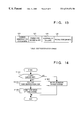
- FIG. 13 shows the format of identification codes for public-use for the radio terminal of the third embodiment.
- FIG. 14 is a flow chart showing the sequence for setting radio identification codes for the radio terminal of the third embodiment.
- FIG. 1 is a block diagram showing the system arrangement of a digital cordless telephone system according to the first embodiment of the present invention.
- reference numerals 101 to 104 denote radio base stations (BS 1 to BS 4 ); 105 , a radio terminal personal station (PS); and 106 , a communication controller (CE).
- BS 1 to BS 4 radio base stations
- PS radio terminal personal station
- CE communication controller
- the communication controller CE comprises interfaces 161 , 162 , and 163 for accommodating the radio base stations BS 1 to BS 4 , a public network, and telephone sets, an exchange switch (SW) 164 , and a central control unit (CC) 165 .
- the CC 165 has an internal memory for storing control programs, various setting data, and the like.
- FIG. 2 is a block diagram showing the arrangement of the radio base station BS in this embodiment.
- the radio base station BS comprises a CPU 21 having an internal memory for storing control programs, various setting data, and the like, an antenna 22 , a transmission/reception multiplexer 23 , a synthesizer 24 , a transmitter 25 , a receiver 26 , a line interface 27 , and a channel codec 28 .
- the CPU 21 controls the radio base station BS.
- the antenna 22 transmits/receives radio waves.
- the multiplexer 23 selects one of the transmitter 25 and the receiver 26 .
- the synthesizer 24 performs frequency selection.
- the transmitter 25 performs down conversion, demodulation, and the like.
- the receiver 26 performs QPSK encoding, quadrature modulation, up conversion, power amplification, and the like.
- the line interface 27 performs communications with the communication controller CE.
- the codec 28 includes an ADPCM codec and the like.
- the CPU 21 receives a received electric field strength signal from the receiver 26 .
- FIG. 3 is a block diagram showing the arrangement of the radio terminal PS in this embodiment.
- the radio terminal PS comprises a CPU 31 having an internal memory for storing control programs, various setting data, and the like, an antenna 32 , a transmission/reception multiplexer 33 , a synthesizer 34 , a transmitter 35 , a receiver 36 , a channel codec 37 , a microphone 38 , a loudspeaker 39 , and a key/display unit 30 .
- the CPU 31 controls the radio terminal PS.
- the antenna 32 transmits/receives radio waves.
- the multiplexer 33 selects one of the transmitter 35 and the receiver 36 .
- the synthesizer 34 performs frequency selection.
- the transmitter 35 performs down conversion, demodulation, and the like.
- the receiver 36 performs QPSK encoding, quadrature modulation, up conversion, power amplification, and the like.
- the codec 37 includes an ADPCM codec and the like.
- the CPU 31 receives a received electric field strength signal from the receiver 36 .
- FIG. 4 shows the principle of connections among the terminals 105 (PS) in the digital cordless telephone system according to the first embodiment of the present invention.
- reference numerals 1051 to 1053 denote radio terminals (PS 1 to PS 3 ) for the digital cordless telephone system.
- radio terminals 105 (PS) When these radio terminals 105 (PS) are present in a single radio service area, they can communicate with each other, without relying upon the radio base station, upon establishment of a radio line between them.
- radio terminals In radio intercommunications between these radio terminals (PS), since no specific control signal transmission channel is assigned, a calling party detects an idle channel and transmits connection request information for a prescribed period of time.
- a radio terminal (PS) which is in a standby state scans channels to receive the connection request information, thus starting a communication.
- FIG. 5 shows the format of identification codes used for connecting radio terminals (PS) in the digital cordless telephone system of this embodiment.
- a system call code 501 is a 29-bit call code assigned to each system when a radio terminal (PS) is used in a private-mode-like communications in a single system. The interconnection between radio terminals (PS) can be attained when system call codes of these radio terminals match with each other.
- a PS call number 502 is a logic number which is effective for only the interconnection between radio terminals (PS), and consists of 13 bits.
- the PS call number 502 corresponds to a terminal (PS) extension number open to a user.
- a PS call code 503 is a 28-bit code assigned to each terminal (PS).
- different priority-monitor-target speech communication channel groups are set in units of the PS call numbers 502 .
- different priority-monitor-target speech communication channels are set in units of radio terminals.
- the priority-monitor-target speech communication channel is a channel which is preferentially searched upon search for a channel to be used in a communication between radio terminals (PS).
- the priority-monitor-target speech communication channel is set by a predetermined method, e.g., by multiplying the PS call number 502 with a predetermined function, or assigning channels in units of PS call numbers.
- FIG. 6 shows the channel scan patterns in units of radio terminals (PS) in this embodiment.
- the terminal PS 1 uses channels “01”, “31”, and “61”
- the terminal PS 2 uses channels “02”, “32”, and “62”
- the terminal PS 3 uses channels “03”, “33”, and “63”, as priority-monitor-target speech communication channels.
- Reference numeral 300 denotes a monitor period of a control channel for public-use used when a radio terminal PS which is accommodated in the radio base terminal BS 1 , performs a communication using the radio base station BS 4 connected via the public line; 301 , a monitor period of a control channel for private-use used in a communication via the base station in a single system; 302 , a monitor period for the priority-monitor-target speech communication channel group; and 303 , a monitor period for a speech communication channel group other than the priority-monitor-target speech communication channel group.
- FIG. 7 is a flow chart showing the scan control sequence in the digital cordless telephone system according to this embodiment.
- the type of a channel which has been monitored so far is discriminated in response to a time-out signal, which is regarded as a trigger signal, from a monitor timer (not shown) for measuring the monitor period of each channel.
- step S 701 in FIG. 7 it is checked if a control channel for public-use is being monitored. If YES in step S 701 , a control channel for private-use is set to be the channel to be monitored next, and a timer for measuring monitor time of the control channel for private-use is started (step S 702 ).
- step S 704 if NO in step S 701 , and if it is determined in step S 703 that the control channel for private-use is being monitored, a speech communication channel corresponding to a scan request condition is set to be the channel to be monitored next, and a timer for measuring the speech channel monitor time is started (step S 704 ).
- step S 705 if the monitor channel is neither the control channel for public-use nor the control channel for private-use, it is determined that a speech communication channel is being monitored, and it is checked in step S 705 if the monitor channel is the speech communication channel other than the priority-monitor-target speech communication channels. If YES in step S 705 , a request for setting the priority-monitor-target speech communication channel to be the speech communication channel which will be monitored next time, is set in step S 706 .
- step S 705 it is checked if the priority-monitor-target speech communication channels have been monitored for one scan cycle during the current monitoring (step S 707 ). If YES in step S 707 , a request for setting a speech communication channel other than the priority-monitor-target speech communication channels to be the speech communication channel which will be monitored next time, is set in step S 708 .
- one scan cycle means a period until all the priority-monitor-target speech communication channels are monitored once.
- One scan cycle ends when all the channels “01”, “31”, and “61” as the priority-monitor-target speech communication channels are monitored, and speech communication channels other than the priority-monitor-target speech communication channels are monitored as the speech communication channels to be monitored next.
- the control channel for public-use and the control channel for private-use are monitored, one speech communication channel is monitored.
- the priority-monitor-target speech communication channels are preferentially monitored, and after all the priority-monitor-target speech communication channels are monitored, a speech communication channel other than the priority-monitor-target speech communication channels is monitored.
- the above-mentioned request is not set to continuously monitor the priority-monitor-target speech communication channel at the next cycle.
- control channel for public-use is set to be the channel to be monitored next, and a timer for measuring the monitor time for the control channel for public-use is started in step S 709 .
- FIG. 8 is a flow chart showing the processing sequence for determining a channel which can be used, upon a call originating operation of a radio terminal (PS) for the digital cordless telephone system of this embodiment.
- PS radio terminal
- a destination or callee to be connected is discriminated based on input information in step S 801 . It is checked in step S 802 if the destination to be connected (current connection) is a radio terminal, that is, an interconnection between the radio terminals. If NO in step S 802 , a call originating control signal is transmitted using a control channel (for private-use or for public-use) corresponding to the terminal mode (step S 803 ).
- step S 802 priority-monitor-target speech communication channels are determined, on the basis of the setting method used upon setting the priority-monitor-target speech communication channels at the destination terminal, using the PS call number 502 of the destination terminal shown in FIG. 5 (step S 804 ).
- step S 805 it is confirmed if the priority-monitor-target speech communication channels include an idle channel.
- step S 805 a call originating control signal is transmitted in step S 806 , using the priority-monitor-target speech communication channel which has been confirmed to be idle in step S 805 .
- a calling signal is transmitted using an idle speech communication channel other than the priority-monitor-target speech communication channels in step S 807 .
- a priority-monitor-target speech communication channel is not confirmed to be an idle more than a predetermined number of times in step S 805 , the channel is excluded from the priority-monitor-target speech communication channels, and is set to be a speech communication channel other than the priority-monitor-target speech communication channels from the next scan cycle, thereby further shortening the connection processing time when interconnection is executed between radio terminals.
- the calling terminal transmits a calling signal by preferentially using a priority-monitor-target speech communication channel which is frequently monitored by a destination terminal, thereby shortening the connection processing time required for interconnecting the radio terminals.
- the digital cordless telephone system has been exemplified as a radio communication system.
- the present invention is not limited to this, but may be applied to interconnections between terminals in a digital cellular (digital automobile telephone) system and a digital cordless telephone system such as DECT (Digital European Cordless Telephone), PCS (Personal Communication System) and the like, which adopt a TDD (Time Division Duplex) method, a TDMA (Time Division Multiple Access) method.
- DECT Digital European Cordless Telephone
- PCS Personal Communication System
- TDD Time Division Duplex
- TDMA Time Division Multiple Access
- FIG. 9 is a block diagram showing the arrangement of a digital cordless telephone terminal according to the second embodiment of the present invention.
- reference numeral 1101 denotes a digital cordless telephone terminal (PS); and 1102 , an IC card which is inserted in the digital cordless telephone terminal (PS) 1101 , stores a radio identification code, and does not require any back-up battery.
- FIG. 10 is a block diagram showing the internal arrangement of the digital cordless telephone terminal.
- reference numeral 301 denotes an IC card interface, which is used for the externally inserted IC card.
- Reference numeral 302 denotes an IC card which stores a radio identification code.
- Other portions of the digital cordless telephone terminal shown in FIG. 10 are the same as those in the first embodiment, and a detailed description thereof will be omitted.
- the above-mentioned digital cordless telephone terminal is used in the system which is described as the first embodiment.
- the IC card to be inserted in the digital cordless telephone terminal stores a PS call number which is different in units of IC cards.
- FIG. 11 is a block diagram showing the system arrangement of a digital cordless telephone system according to the third embodiment of the present invention.
- reference numeral 1101 denotes a digital cordless telephone terminal (PS); and 1102 , an IC card which is inserted in the digital cordless telephone terminal (PS) 1101 , stores a radio identification code, and does not require any back-up battery.
- Reference numerals 1103 and 1104 denote digital cordless telephone radio base stations.
- the digital cordless telephone radio base station 1103 is provided by a common carrier A, and the digital cordless telephone radio base station 1104 is provided by a common carrier B.
- FIGS. 12 and 13 show the formats of the identification codes for the terminal (PS) in the digital cordless telephone system of this embodiment. More specifically, FIG. 12 shows the format of an identification code for private-use, which includes a system call code 121 , an additional ID 122 , and a PS call code 123 .
- FIG. 13 shows the format of an identification code for public-use, which includes a carrier identification code 124 , a paging area number 125 , an additional ID 126 , and a PS call code 123 .
- the digital cordless telephone radio base stations shown FIG. 11 use a single radio medium, but are provided by different common carriers. For this reason, these carriers have different values of the carrier identification code 124 shown in FIG. 13 .
- the carrier identification code 124 In order to permit a radio connection between the digital cordless telephone radio base station 1103 (common carrier A) and the digital cordless telephone radio base station 1104 (common carrier B), the carrier identification code 124 must be switched as needed.
- FIG. 14 is a flow chart showing the sequence for setting a radio identification code in the digital cordless telephone terminal (PS) in the digital cordless telephone system of this embodiment.
- step S 1401 in FIG. 14 it is checked if the IC card 1102 is set in the digital cordless telephone terminal (PS). If NO in step S 1401 , the operation associated with radio system processing is inhibited (step S 1404 ).
- step S 1401 the radio identification code is read out from the IC card in step S 1402 , and the operation associated with the radio system is permitted in step S 1403 .
- radio identification codes can be assigned in units of users.
- the digital cordless telephone system has been exemplified as a radio communication system.
- the present invention is not limited to this, but may be applied to interconnections between terminals in a digital cellular (digital automobile telephone) system and a digital cordless telephone system such as DECT (Digital European Cordless Telephone), PCS (Personal Communication System) and the like, which adopt a TDD (Time Division Duplex) method, a TDMA (Time Division Multiple Access) method.
- DECT Digital European Cordless Telephone
- PCS Personal Communication System
- TDD Time Division Duplex
- TDMA Time Division Multiple Access
- the IC card is used as a nonvolatile storage medium.
- other nonvolatile storage media such as a magnetooptical card, a magnetic card, and the like may be used.
- the present invention may be applied to a system constituted by a plurality of apparatuses or an apparatus constituted by a single device.
- the present invention can also be applied to a case wherein the invention is achieved by supplying a program stored in a storage medium to the system or the apparatus.
Abstract
In a radio communication system, when an interconnection between radio terminal (PS) used for digital cordless telephones is performed, a connection destination terminal is discriminated in accordance with input information. If it s determined that the connection designation terminal is a terminal involved in the interconnection, a priority-monitor-target communication channel is figured out in accordance with a PS call number of the destination. When the priority-monitor-target communication channel is not used, transmission of call-origination control signal is started by using the idle priority-monitor-target communication channel. That is, the call-original control signal is transmitted by preferentially using the priority-monitor-target communication channel which is frequently monitored by the destination terminal.
Description
This is a divisional of application Ser. No. 08/508,309 filed Jul. 27, 1995 now U.S. Pat. No. 5,867,790.
1. Field of the Invention
The present invention relates to a radio communication system which realizes intercommunications between radio terminals.
2. Description of the Related Art
Conventionally, in a normal communication system adopting a simplex method which is known as the method of making radio connections without using a specific channel for transmitting control signals, a calling party detects an idle channel and transmits connection request information for a prescribed period of time. A radio terminal which is in a standby state scans all the channels to receive the connection request information.
However, in the simplex method, there is a high probability for the radio terminal to scan all the channels before it receives a calling signal, and a considerably long time is required until connection is achieved.
It is an object of the present invention to provide a radio communication system which can shorten the connection processing time required for connecting radio terminals to each other.
It is another object of the present invention to provide a radio communication system which allows an interworking among a plurality of radio communication networks with a simple operation.
It is still another object of the present invention to provide a radio communication system which allows an interworking among a plurality of radio communication networks with a simple structure.
In order to achieve the above objects, according to a preferred aspect of the present invention, there is disclosed a radio communication system, which comprises a radio base station which accommodates a plurality of radio communication terminals in a radio communication area, and a plurality of radio communication terminals each of which performs a communication using a control channel and a communication channel when the communication is performed via said radio base station, comprising: communication means for performing a communication with another radio communication terminal using the communication channel without using the control channel; setting means for setting at least one specific communication channel from a plurality of communication channels; confirmation means for preferentially confirming an idle state of the specific communication channel among all the communication channels; and connection means for connecting a radio line with a destination radio communication terminal in accordance with a result obtained by said confirmation means.
There is also disclosed a communication method for a radio communication system, which comprises a radio base station which accommodates a plurality of radio communication terminals in a radio communication area, and a plurality of radio communication terminals each of which performs a communication using a control channel and a communication channel when the communication is performed via said radio base station, comprising the steps of: setting at least one specific communication channel from a plurality of communication channels when a communication is performed with another radio communication terminal using the communication channel without using the control channel; preferentially confirming an idle state of the specific communication channel among all the communication channels; and connecting a radio line with a destination radio communication terminal in accordance with a result obtained in the confirmation step.
Other features and advantages of the present invention will be apparent from the following description taken in conjunction with the accompanying drawings, in which like reference characters designate the same or similar parts throughout the figures thereof.
FIG. 1 is a block diagram of a digital cordless telephone system according to the first embodiment of the present invention;
FIG. 2 is a block diagram showing the internal arrangement of a radio base station of the first embodiment;
FIG. 3 is a block diagram showing the internal arrangement of a radio terminal of the first embodiment;
FIG. 4 is a schematic view showing the principle of connections among radio terminals of the first embodiment;
FIG. 5 shows the format of identification codes used for connecting radio terminals;
FIG. 6 shows the channel scan pattern of the radio terminal of the first embodiment;
FIG. 7 is a flow chart showing the scan control sequence of the radio terminal of the first embodiment;
FIG. 8 is a flow chart showing the processing sequence for determining a use channel upon a call originating operation in the radio terminal of the first embodiment;
FIG. 9 is a block diagram showing a digital cordless telephone system according to the second embodiment of the present invention;
FIG. 10 is a block diagram showing the internal arrangement of a radio terminal of the second embodiment;
FIG. 11 is a block diagram showing a digital cordless telephone system according to the third embodiment of the present invention;
FIG. 12 shows the format of identification codes for private-use for a radio terminal of the third embodiment;
FIG. 13 shows the format of identification codes for public-use for the radio terminal of the third embodiment; and
FIG. 14 is a flow chart showing the sequence for setting radio identification codes for the radio terminal of the third embodiment.
The preferred embodiment of the present invention will be described in detail hereinafter with reference to the accompanying drawings.
FIG. 1 is a block diagram showing the system arrangement of a digital cordless telephone system according to the first embodiment of the present invention.
Referring to FIG. 1, reference numerals 101 to 104 denote radio base stations (BS1 to BS4); 105, a radio terminal personal station (PS); and 106, a communication controller (CE).
The communication controller CE comprises interfaces 161, 162, and 163 for accommodating the radio base stations BS1 to BS4, a public network, and telephone sets, an exchange switch (SW) 164, and a central control unit (CC) 165. The CC 165 has an internal memory for storing control programs, various setting data, and the like.
FIG. 2 is a block diagram showing the arrangement of the radio base station BS in this embodiment.
The radio base station BS comprises a CPU 21 having an internal memory for storing control programs, various setting data, and the like, an antenna 22, a transmission/reception multiplexer 23, a synthesizer 24, a transmitter 25, a receiver 26, a line interface 27, and a channel codec 28.
The CPU 21 controls the radio base station BS. The antenna 22 transmits/receives radio waves.
The multiplexer 23 selects one of the transmitter 25 and the receiver 26. The synthesizer 24 performs frequency selection.
The transmitter 25 performs down conversion, demodulation, and the like. The receiver 26 performs QPSK encoding, quadrature modulation, up conversion, power amplification, and the like. The line interface 27 performs communications with the communication controller CE. The codec 28 includes an ADPCM codec and the like. The CPU 21 receives a received electric field strength signal from the receiver 26.
FIG. 3 is a block diagram showing the arrangement of the radio terminal PS in this embodiment.
The radio terminal PS comprises a CPU 31 having an internal memory for storing control programs, various setting data, and the like, an antenna 32, a transmission/reception multiplexer 33, a synthesizer 34, a transmitter 35, a receiver 36, a channel codec 37, a microphone 38, a loudspeaker 39, and a key/display unit 30.
The CPU 31 controls the radio terminal PS. The antenna 32 transmits/receives radio waves. The multiplexer 33 selects one of the transmitter 35 and the receiver 36. The synthesizer 34 performs frequency selection.
The transmitter 35 performs down conversion, demodulation, and the like. The receiver 36 performs QPSK encoding, quadrature modulation, up conversion, power amplification, and the like. The codec 37 includes an ADPCM codec and the like. The CPU 31 receives a received electric field strength signal from the receiver 36.
FIG. 4 shows the principle of connections among the terminals 105 (PS) in the digital cordless telephone system according to the first embodiment of the present invention. In FIG. 4, reference numerals 1051 to 1053 denote radio terminals (PS1 to PS3) for the digital cordless telephone system. When these radio terminals 105 (PS) are present in a single radio service area, they can communicate with each other, without relying upon the radio base station, upon establishment of a radio line between them.
In radio intercommunications between these radio terminals (PS), since no specific control signal transmission channel is assigned, a calling party detects an idle channel and transmits connection request information for a prescribed period of time. A radio terminal (PS) which is in a standby state scans channels to receive the connection request information, thus starting a communication.
FIG. 5 shows the format of identification codes used for connecting radio terminals (PS) in the digital cordless telephone system of this embodiment. Referring to FIG. 5, a system call code 501 is a 29-bit call code assigned to each system when a radio terminal (PS) is used in a private-mode-like communications in a single system. The interconnection between radio terminals (PS) can be attained when system call codes of these radio terminals match with each other.
A PS call number 502 is a logic number which is effective for only the interconnection between radio terminals (PS), and consists of 13 bits. The PS call number 502 corresponds to a terminal (PS) extension number open to a user. A PS call code 503 is a 28-bit code assigned to each terminal (PS).
Of the identification codes, different priority-monitor-target speech communication channel groups are set in units of the PS call numbers 502. In a single system, since different PS call numbers are assigned to the individual terminals, different priority-monitor-target speech communication channels are set in units of radio terminals.
The priority-monitor-target speech communication channel is a channel which is preferentially searched upon search for a channel to be used in a communication between radio terminals (PS). The priority-monitor-target speech communication channel is set by a predetermined method, e.g., by multiplying the PS call number 502 with a predetermined function, or assigning channels in units of PS call numbers.
FIG. 6 shows the channel scan patterns in units of radio terminals (PS) in this embodiment. In this embodiment, as shown in FIG. 6, the terminal PS1 uses channels “01”, “31”, and “61”, the terminal PS2 uses channels “02”, “32”, and “62”, and the terminal PS3 uses channels “03”, “33”, and “63”, as priority-monitor-target speech communication channels.
In FIG. 6, Reference numeral 300 denotes a monitor period of a control channel for public-use used when a radio terminal PS which is accommodated in the radio base terminal BS1, performs a communication using the radio base station BS4 connected via the public line; 301, a monitor period of a control channel for private-use used in a communication via the base station in a single system; 302, a monitor period for the priority-monitor-target speech communication channel group; and 303, a monitor period for a speech communication channel group other than the priority-monitor-target speech communication channel group.
Scan control for realizing the scan patterns shown in FIG. 6 will be explained below.
FIG. 7 is a flow chart showing the scan control sequence in the digital cordless telephone system according to this embodiment. In this embodiment, the type of a channel which has been monitored so far is discriminated in response to a time-out signal, which is regarded as a trigger signal, from a monitor timer (not shown) for measuring the monitor period of each channel.
In step S701 in FIG. 7, it is checked if a control channel for public-use is being monitored. If YES in step S701, a control channel for private-use is set to be the channel to be monitored next, and a timer for measuring monitor time of the control channel for private-use is started (step S702).
However, if NO in step S701, and if it is determined in step S703 that the control channel for private-use is being monitored, a speech communication channel corresponding to a scan request condition is set to be the channel to be monitored next, and a timer for measuring the speech channel monitor time is started (step S704).
On the other hand, if the monitor channel is neither the control channel for public-use nor the control channel for private-use, it is determined that a speech communication channel is being monitored, and it is checked in step S705 if the monitor channel is the speech communication channel other than the priority-monitor-target speech communication channels. If YES in step S705, a request for setting the priority-monitor-target speech communication channel to be the speech communication channel which will be monitored next time, is set in step S706.
However, if NO in step S705, it is checked if the priority-monitor-target speech communication channels have been monitored for one scan cycle during the current monitoring (step S707). If YES in step S707, a request for setting a speech communication channel other than the priority-monitor-target speech communication channels to be the speech communication channel which will be monitored next time, is set in step S708.
Note that one scan cycle means a period until all the priority-monitor-target speech communication channels are monitored once.
Take the radio terminal PS1 in FIG. 6 for example. One scan cycle ends when all the channels “01”, “31”, and “61” as the priority-monitor-target speech communication channels are monitored, and speech communication channels other than the priority-monitor-target speech communication channels are monitored as the speech communication channels to be monitored next. In this manner, after the control channel for public-use and the control channel for private-use are monitored, one speech communication channel is monitored. In this case, the priority-monitor-target speech communication channels are preferentially monitored, and after all the priority-monitor-target speech communication channels are monitored, a speech communication channel other than the priority-monitor-target speech communication channels is monitored.
On the other hand, if it is determined that one scan cycle has not ended, the above-mentioned request is not set to continuously monitor the priority-monitor-target speech communication channel at the next cycle.
After the end of speech communication channel monitor discrimination (steps S705 to S708), the control channel for public-use is set to be the channel to be monitored next, and a timer for measuring the monitor time for the control channel for public-use is started in step S709.
FIG. 8 is a flow chart showing the processing sequence for determining a channel which can be used, upon a call originating operation of a radio terminal (PS) for the digital cordless telephone system of this embodiment.
Referring to FIG. 8, a destination or callee to be connected is discriminated based on input information in step S801. It is checked in step S802 if the destination to be connected (current connection) is a radio terminal, that is, an interconnection between the radio terminals. If NO in step S802, a call originating control signal is transmitted using a control channel (for private-use or for public-use) corresponding to the terminal mode (step S803).
On the other hand, if YES in step S802, priority-monitor-target speech communication channels are determined, on the basis of the setting method used upon setting the priority-monitor-target speech communication channels at the destination terminal, using the PS call number 502 of the destination terminal shown in FIG. 5 (step S804). In step S805, it is confirmed if the priority-monitor-target speech communication channels include an idle channel.
If YES in step S805, a call originating control signal is transmitted in step S806, using the priority-monitor-target speech communication channel which has been confirmed to be idle in step S805. However, if NO in step S805, a calling signal is transmitted using an idle speech communication channel other than the priority-monitor-target speech communication channels in step S807.
If a priority-monitor-target speech communication channel is not confirmed to be an idle more than a predetermined number of times in step S805, the channel is excluded from the priority-monitor-target speech communication channels, and is set to be a speech communication channel other than the priority-monitor-target speech communication channels from the next scan cycle, thereby further shortening the connection processing time when interconnection is executed between radio terminals.
As described above, according to this embodiment, when radio terminals (PS) for the digital cordless telephone system are to achieve an interconnection between the terminals (interconnection between terminals PS), the calling terminal transmits a calling signal by preferentially using a priority-monitor-target speech communication channel which is frequently monitored by a destination terminal, thereby shortening the connection processing time required for interconnecting the radio terminals.
In this embodiment, the digital cordless telephone system has been exemplified as a radio communication system. However, the present invention is not limited to this, but may be applied to interconnections between terminals in a digital cellular (digital automobile telephone) system and a digital cordless telephone system such as DECT (Digital European Cordless Telephone), PCS (Personal Communication System) and the like, which adopt a TDD (Time Division Duplex) method, a TDMA (Time Division Multiple Access) method.
The second embodiment of the present invention will be described below.
FIG. 9 is a block diagram showing the arrangement of a digital cordless telephone terminal according to the second embodiment of the present invention.
Referring to FIG. 9, reference numeral 1101 denotes a digital cordless telephone terminal (PS); and 1102, an IC card which is inserted in the digital cordless telephone terminal (PS) 1101, stores a radio identification code, and does not require any back-up battery.
FIG. 10 is a block diagram showing the internal arrangement of the digital cordless telephone terminal.
Referring to FIG. 10, reference numeral 301 denotes an IC card interface, which is used for the externally inserted IC card. Reference numeral 302 denotes an IC card which stores a radio identification code. Other portions of the digital cordless telephone terminal shown in FIG. 10 are the same as those in the first embodiment, and a detailed description thereof will be omitted.
In the second embodiment, the above-mentioned digital cordless telephone terminal is used in the system which is described as the first embodiment.
The IC card to be inserted in the digital cordless telephone terminal stores a PS call number which is different in units of IC cards.
In the digital cordless telephone terminal shown in FIGS. 9 and 10, when a connection using a priority-monitor-target speech communication channel cannot be successfully achieved for some unknown-reason such as radio disturbance, or when an idle priority-monitor-target speech communication channel cannot be confirmed, information indicating this status is given to a user using a display unit 30 or a loudspeaker 39. Upon reception of this information, the user exchanges the IC card with another one. Thus, the PS call number of the digital cordless telephone terminal changes, and the priority-monitor-target speech communication channels are also changed.
With this arrangement, radio channels can be used more efficiently.
The third embodiment of the present invention will be described below.
In the third embodiment, another application of the digital cordless telephone terminal of the second embodiment will be explained.
FIG. 11 is a block diagram showing the system arrangement of a digital cordless telephone system according to the third embodiment of the present invention.
Referring to FIG. 11, reference numeral 1101 denotes a digital cordless telephone terminal (PS); and 1102, an IC card which is inserted in the digital cordless telephone terminal (PS) 1101, stores a radio identification code, and does not require any back-up battery. Reference numerals 1103 and 1104 denote digital cordless telephone radio base stations. The digital cordless telephone radio base station 1103 is provided by a common carrier A, and the digital cordless telephone radio base station 1104 is provided by a common carrier B.
Since the arrangement of the digital cordless telephone terminal shown in FIG. 11 is the same as that in the second embodiment, and the arrangement of each of the radio base stations 1103 and 1104 is the same as that in the first embodiment, a detailed description thereof will be omitted.
FIGS. 12 and 13 show the formats of the identification codes for the terminal (PS) in the digital cordless telephone system of this embodiment. More specifically, FIG. 12 shows the format of an identification code for private-use, which includes a system call code 121, an additional ID 122, and a PS call code 123.
FIG. 13 shows the format of an identification code for public-use, which includes a carrier identification code 124, a paging area number 125, an additional ID 126, and a PS call code 123.
The digital cordless telephone radio base stations shown FIG. 11 use a single radio medium, but are provided by different common carriers. For this reason, these carriers have different values of the carrier identification code 124 shown in FIG. 13. In order to permit a radio connection between the digital cordless telephone radio base station 1103 (common carrier A) and the digital cordless telephone radio base station 1104 (common carrier B), the carrier identification code 124 must be switched as needed.
The setting operation of the radio identification code in the digital cordless telephone terminal (PS) in the digital cordless telephone system of this embodiment will be explained below.
FIG. 14 is a flow chart showing the sequence for setting a radio identification code in the digital cordless telephone terminal (PS) in the digital cordless telephone system of this embodiment. In step S1401 in FIG. 14, it is checked if the IC card 1102 is set in the digital cordless telephone terminal (PS). If NO in step S1401, the operation associated with radio system processing is inhibited (step S1404).
However, if YES in step S1401, the radio identification code is read out from the IC card in step S1402, and the operation associated with the radio system is permitted in step S1403.
As described above, according to this embodiment, by exchanging an IC card which is set in the radio terminal and stores a radio identification code, various radio identification codes corresponding to a plurality of radio communication networks with different carrier identification codes can be switched. Therefore, a cumbersome procedure for storing a radio identification code in an internal storage medium of the terminal can be eliminated, and the radio terminal and the medium which stores radio identification information can be independently managed. Furthermore, roaming between a plurality of radio communication networks can be realized.
In addition, an end user need not store radio identification codes, and radio identification codes can be assigned in units of users.
In the second and third embodiments, the digital cordless telephone system has been exemplified as a radio communication system. However, the present invention is not limited to this, but may be applied to interconnections between terminals in a digital cellular (digital automobile telephone) system and a digital cordless telephone system such as DECT (Digital European Cordless Telephone), PCS (Personal Communication System) and the like, which adopt a TDD (Time Division Duplex) method, a TDMA (Time Division Multiple Access) method.
Furthermore, in the second and third embodiments, the IC card is used as a nonvolatile storage medium. Alternatively, other nonvolatile storage media such as a magnetooptical card, a magnetic card, and the like may be used.
The present invention may be applied to a system constituted by a plurality of apparatuses or an apparatus constituted by a single device. The present invention can also be applied to a case wherein the invention is achieved by supplying a program stored in a storage medium to the system or the apparatus.
As many apparently widely different embodiments of the present invention can be made without departing from the spirit and scope thereof, it is to be understood that the invention is not limited to the specific embodiments thereof except as defined in the appended claims.
Claims (5)
1. A communication apparatus comprising:
insertion means where an external storage medium storing at least information used for an incoming call is inserted;
determination means for determining at least one communication channel to be monitored preferentially on the basis of information stored in the external storage medium inserted into said insertion means;
monitoring means for discriminating whether or not said incoming call is received by monitoring preferentially the communication channel determined by said determination means,
wherein, when another external storage medium storing information different from said information stored said external storage medium is inserted into said insertion means, said determination means re-determines a communication channel to be monitored preferentially.
2. The communication apparatus according to claim 1 , wherein one of system identification information identifying the communication system is stored in said external storage medium.
3. The communication apparatus according to claim 1 , wherein said communication apparatus performs communication using a radio line.
4. The communication apparatus according to claim 3 , wherein said communication apparatus performs communication through a radio base station of the communication system corresponding to the communication system information stored in the external storage medium.
5. A communication apparatus comprising:
a communication control unit arranged to perform communication using at least one of a plurality of communication channels;
an insertion unit where an external storage medium storing at least information used for an incoming call of said communication apparatus is inserted;
a determination unit arranged to determine at least one of said plurality of communication channels as a communication channel to be minitored preferentially on the basis of information stored in said external storage medium when said external storage medium is inserted into said insertion means; and
a monitoring unit arranged to discriminate whether or not incoming call is received by monitoring preferentially the communication channel determined by said determination unit.
Priority Applications (1)
| Application Number | Priority Date | Filing Date | Title |
|---|---|---|---|
| US09/126,468 US6519476B1 (en) | 1994-07-28 | 1998-07-30 | Radio communication system wherein insertion of an attachable external storage medium causes the mobile to interact with the system |
Applications Claiming Priority (4)
| Application Number | Priority Date | Filing Date | Title |
|---|---|---|---|
| JP17655694 | 1994-07-28 | ||
| JP6-176556 | 1994-07-28 | ||
| US08/508,309 US5867790A (en) | 1994-07-28 | 1995-07-27 | Radio communication system with enhanced connection processing |
| US09/126,468 US6519476B1 (en) | 1994-07-28 | 1998-07-30 | Radio communication system wherein insertion of an attachable external storage medium causes the mobile to interact with the system |
Related Parent Applications (1)
| Application Number | Title | Priority Date | Filing Date |
|---|---|---|---|
| US08/508,309 Division US5867790A (en) | 1994-07-28 | 1995-07-27 | Radio communication system with enhanced connection processing |
Publications (1)
| Publication Number | Publication Date |
|---|---|
| US6519476B1 true US6519476B1 (en) | 2003-02-11 |
Family
ID=16015650
Family Applications (2)
| Application Number | Title | Priority Date | Filing Date |
|---|---|---|---|
| US08/508,309 Expired - Fee Related US5867790A (en) | 1994-07-28 | 1995-07-27 | Radio communication system with enhanced connection processing |
| US09/126,468 Expired - Fee Related US6519476B1 (en) | 1994-07-28 | 1998-07-30 | Radio communication system wherein insertion of an attachable external storage medium causes the mobile to interact with the system |
Family Applications Before (1)
| Application Number | Title | Priority Date | Filing Date |
|---|---|---|---|
| US08/508,309 Expired - Fee Related US5867790A (en) | 1994-07-28 | 1995-07-27 | Radio communication system with enhanced connection processing |
Country Status (1)
| Country | Link |
|---|---|
| US (2) | US5867790A (en) |
Cited By (2)
| Publication number | Priority date | Publication date | Assignee | Title |
|---|---|---|---|---|
| US20050037732A1 (en) * | 2003-08-12 | 2005-02-17 | Motorola, Inc. | Method and apparatus for locking a wireless communication unit to a selected network |
| US20060072520A1 (en) * | 2000-03-23 | 2006-04-06 | Chitrapu Prabhakar R | Time synchronized standby state to the GPRS medium access control protocol with applications to mobile satellite systems |
Families Citing this family (8)
| Publication number | Priority date | Publication date | Assignee | Title |
|---|---|---|---|---|
| US5949017A (en) * | 1996-06-18 | 1999-09-07 | Abb Power T&D Company Inc. | Electrical transformers containing electrical insulation fluids comprising high oleic acid oil compositions |
| US7050445B1 (en) | 1997-07-30 | 2006-05-23 | Bellsouth Intellectual Property Corporation | System and method for dynamic allocation of capacity on wireless networks |
| US7065061B1 (en) * | 1997-07-30 | 2006-06-20 | Bellsouth Intellectual Property Corporation | System and method for providing data services using idle cell resources |
| US7046643B1 (en) | 1997-07-30 | 2006-05-16 | Bellsouth Intellectual Property Corporation | Method for dynamic multi-level pricing for wireless communications according to quality of service |
| US6069882A (en) | 1997-07-30 | 2000-05-30 | Bellsouth Intellectual Property Corporation | System and method for providing data services using idle cell resources |
| US7349333B2 (en) | 1997-07-30 | 2008-03-25 | At&T Delaware Intellectual Property, Inc. | Associated systems and methods for providing data services using idle cell resources |
| US6745043B1 (en) * | 1998-09-03 | 2004-06-01 | Siemens Information & Communications Mobile, Llc | Priorty communication system and method of operation |
| US7006831B2 (en) * | 2002-09-27 | 2006-02-28 | Bellsouth Intellectual Property Corporation | Apparatus and method for providing dynamic communications network traffic control |
Citations (14)
| Publication number | Priority date | Publication date | Assignee | Title |
|---|---|---|---|---|
| US4672601A (en) | 1984-12-06 | 1987-06-09 | Motorola, Inc. | Duplex interconnect/dispatch trunked radio system |
| US5235598A (en) | 1992-01-30 | 1993-08-10 | Motorola, Inc. | Method for utilizing a control channel for both data and voice |
| US5331123A (en) * | 1992-06-01 | 1994-07-19 | Motorola Inc. | Switch operative responsive to positioning of a card member |
| US5353328A (en) * | 1992-02-14 | 1994-10-04 | Nokia Mobile Phones Ltd. | Data adapter for a radiotelephone |
| US5404580A (en) * | 1990-02-14 | 1995-04-04 | Motorola, Inc. | Radio having memory means for storing radio user validation code |
| US5442809A (en) | 1991-11-21 | 1995-08-15 | Motorola, Inc. | Method of assigning a voice/data channel as a temporary control channel in a radio communications system |
| US5444764A (en) * | 1993-07-01 | 1995-08-22 | Motorola, Inc. | Method of providing a subscription lock to a radiotelephone system |
| US5448765A (en) * | 1992-02-28 | 1995-09-05 | Nokia Telecommunications Oy | Radio telephone having removable memory containing all essential software, including control parameters |
| US5515366A (en) | 1994-11-17 | 1996-05-07 | International Business Machines Corporation | Method and apparatus for direct communication in a TDMA radio communication system |
| US5778322A (en) * | 1993-07-16 | 1998-07-07 | Ericsson Inc. | Method and apparatus for controlling transceiver operations in a radio communications system to reduce same channel frequency interference |
| US5884168A (en) * | 1996-08-30 | 1999-03-16 | Ericsson, Inc. | Multiple cellular systems with limited sim card information |
| US5903824A (en) * | 1995-07-29 | 1999-05-11 | Mannesman Vdo Ag | RDS-TMC broadcast receiver which substitutes phonetic characters for non-convertible characters prior to synthesizing speech |
| US5946635A (en) * | 1997-08-12 | 1999-08-31 | Dominguez; David C. | Sporting event configurable radio receiver/scanner |
| US6009333A (en) * | 1997-08-14 | 1999-12-28 | Executone Information Systems, Inc. | Telephone communication system having a locator and a scheduling facility |
-
1995
- 1995-07-27 US US08/508,309 patent/US5867790A/en not_active Expired - Fee Related
-
1998
- 1998-07-30 US US09/126,468 patent/US6519476B1/en not_active Expired - Fee Related
Patent Citations (14)
| Publication number | Priority date | Publication date | Assignee | Title |
|---|---|---|---|---|
| US4672601A (en) | 1984-12-06 | 1987-06-09 | Motorola, Inc. | Duplex interconnect/dispatch trunked radio system |
| US5404580A (en) * | 1990-02-14 | 1995-04-04 | Motorola, Inc. | Radio having memory means for storing radio user validation code |
| US5442809A (en) | 1991-11-21 | 1995-08-15 | Motorola, Inc. | Method of assigning a voice/data channel as a temporary control channel in a radio communications system |
| US5235598A (en) | 1992-01-30 | 1993-08-10 | Motorola, Inc. | Method for utilizing a control channel for both data and voice |
| US5353328A (en) * | 1992-02-14 | 1994-10-04 | Nokia Mobile Phones Ltd. | Data adapter for a radiotelephone |
| US5448765A (en) * | 1992-02-28 | 1995-09-05 | Nokia Telecommunications Oy | Radio telephone having removable memory containing all essential software, including control parameters |
| US5331123A (en) * | 1992-06-01 | 1994-07-19 | Motorola Inc. | Switch operative responsive to positioning of a card member |
| US5444764A (en) * | 1993-07-01 | 1995-08-22 | Motorola, Inc. | Method of providing a subscription lock to a radiotelephone system |
| US5778322A (en) * | 1993-07-16 | 1998-07-07 | Ericsson Inc. | Method and apparatus for controlling transceiver operations in a radio communications system to reduce same channel frequency interference |
| US5515366A (en) | 1994-11-17 | 1996-05-07 | International Business Machines Corporation | Method and apparatus for direct communication in a TDMA radio communication system |
| US5903824A (en) * | 1995-07-29 | 1999-05-11 | Mannesman Vdo Ag | RDS-TMC broadcast receiver which substitutes phonetic characters for non-convertible characters prior to synthesizing speech |
| US5884168A (en) * | 1996-08-30 | 1999-03-16 | Ericsson, Inc. | Multiple cellular systems with limited sim card information |
| US5946635A (en) * | 1997-08-12 | 1999-08-31 | Dominguez; David C. | Sporting event configurable radio receiver/scanner |
| US6009333A (en) * | 1997-08-14 | 1999-12-28 | Executone Information Systems, Inc. | Telephone communication system having a locator and a scheduling facility |
Cited By (2)
| Publication number | Priority date | Publication date | Assignee | Title |
|---|---|---|---|---|
| US20060072520A1 (en) * | 2000-03-23 | 2006-04-06 | Chitrapu Prabhakar R | Time synchronized standby state to the GPRS medium access control protocol with applications to mobile satellite systems |
| US20050037732A1 (en) * | 2003-08-12 | 2005-02-17 | Motorola, Inc. | Method and apparatus for locking a wireless communication unit to a selected network |
Also Published As
| Publication number | Publication date |
|---|---|
| US5867790A (en) | 1999-02-02 |
Similar Documents
| Publication | Publication Date | Title |
|---|---|---|
| CN100562152C (en) | Radio telephone system | |
| US5257406A (en) | System and method for controlling radio communication base on a stored schedule | |
| KR100421576B1 (en) | A communication system and a method for providing services to a terminal in such a communication system | |
| EP0188322A2 (en) | A total communication system and communication apparatus for use in such a system | |
| EP0921668B1 (en) | TDMA communication method and system | |
| US6519476B1 (en) | Radio communication system wherein insertion of an attachable external storage medium causes the mobile to interact with the system | |
| US20050119014A1 (en) | Home cellular phone system | |
| JP3083752B2 (en) | Emergency call control method | |
| JP3421984B2 (en) | Wireless communication device | |
| US20020137492A1 (en) | Mobile communication terminal | |
| JP3073843B2 (en) | Digital cordless telephone and base station status information transmission method | |
| JPH03295327A (en) | Movable station extension method for cordless telephone | |
| KR100566997B1 (en) | Radio apparatus for terminal and base in DECT system | |
| JP2981352B2 (en) | Digital cordless telephone | |
| JP3431420B2 (en) | Mobile communication terminal device and base station device of mobile communication system | |
| JPH02249326A (en) | Idle channel designation system | |
| JPH0898238A (en) | Radio communication system, radio communication equipment, and communication method | |
| KR0121965B1 (en) | Method for accessing the time slot of the portable terminal | |
| KR970001865B1 (en) | Method for warning of disconnected state in the portable terminal | |
| KR0123106B1 (en) | Method for accessing the time slot | |
| KR970003978B1 (en) | Method for connecting the fixed station in the portable terminal | |
| JP3473141B2 (en) | Wireless telephone equipment | |
| KR100259053B1 (en) | Method for registering and identifying radio equipment in home base station of digital radio telephone system | |
| JP3058154B2 (en) | Wireless communication device | |
| JP2880360B2 (en) | Digital cordless telephone |
Legal Events
| Date | Code | Title | Description |
|---|---|---|---|
| FEPP | Fee payment procedure |
Free format text: PAYOR NUMBER ASSIGNED (ORIGINAL EVENT CODE: ASPN); ENTITY STATUS OF PATENT OWNER: LARGE ENTITY |
|
| CC | Certificate of correction | ||
| REMI | Maintenance fee reminder mailed | ||
| LAPS | Lapse for failure to pay maintenance fees | ||
| STCH | Information on status: patent discontinuation |
Free format text: PATENT EXPIRED DUE TO NONPAYMENT OF MAINTENANCE FEES UNDER 37 CFR 1.362 |
|
| FP | Lapsed due to failure to pay maintenance fee |
Effective date: 20070211 |