US6508005B2 - Solo plane pin head bow sight - Google Patents

Solo plane pin head bow sight Download PDF

Info

Publication number
US6508005B2
US6508005B2 US09/768,467 US76846701A US6508005B2 US 6508005 B2 US6508005 B2 US 6508005B2 US 76846701 A US76846701 A US 76846701A US 6508005 B2 US6508005 B2 US 6508005B2
Authority
US
United States
Prior art keywords
pin
pins
tracks
bow sight
sight
Prior art date
Legal status (The legal status is an assumption and is not a legal conclusion. Google has not performed a legal analysis and makes no representation as to the accuracy of the status listed.)
Expired - Fee Related, expires
Application number
US09/768,467
Other versions
US20010032393A1 (en
Inventor
Eric C. Springer
Current Assignee (The listed assignees may be inaccurate. Google has not performed a legal analysis and makes no representation or warranty as to the accuracy of the list.)
Copper John Corp
Original Assignee
Copper John Corp
Priority date (The priority date is an assumption and is not a legal conclusion. Google has not performed a legal analysis and makes no representation as to the accuracy of the date listed.)
Filing date
Publication date
Family has litigation
First worldwide family litigation filed litigation Critical https://patents.darts-ip.com/?family=26874021&utm_source=google_patent&utm_medium=platform_link&utm_campaign=public_patent_search&patent=US6508005(B2) "Global patent litigation dataset” by Darts-ip is licensed under a Creative Commons Attribution 4.0 International License.
US case filed in Michigan Western District Court litigation https://portal.unifiedpatents.com/litigation/Michigan%20Western%20District%20Court/case/1%3A08-cv-00073 Source: District Court Jurisdiction: Michigan Western District Court "Unified Patents Litigation Data" by Unified Patents is licensed under a Creative Commons Attribution 4.0 International License.
Application filed by Copper John Corp filed Critical Copper John Corp
Priority to US09/768,467 priority Critical patent/US6508005B2/en
Assigned to COPPER JOHN CORPORATION reassignment COPPER JOHN CORPORATION ASSIGNMENT OF ASSIGNORS INTEREST (SEE DOCUMENT FOR DETAILS). Assignors: SPRINGER, ERIC C.
Publication of US20010032393A1 publication Critical patent/US20010032393A1/en
Application granted granted Critical
Priority to US10/348,473 priority patent/US20030110648A1/en
Publication of US6508005B2 publication Critical patent/US6508005B2/en
Adjusted expiration legal-status Critical
Expired - Fee Related legal-status Critical Current

Links

Images

Classifications

    • FMECHANICAL ENGINEERING; LIGHTING; HEATING; WEAPONS; BLASTING
    • F41WEAPONS
    • F41GWEAPON SIGHTS; AIMING
    • F41G1/00Sighting devices
    • F41G1/46Sighting devices for particular applications
    • F41G1/467Sighting devices for particular applications for bows

Definitions

  • FIGS. 9 and 10 show the pin guard 40 of the exemplary bow sight 10 of FIG. 1 in accordance with the present invention.
  • the pin guard 40 is circular.
  • the circular pin guard 40 forms an integral portion of the sight picture for an archer using the bow sight 10 of the present invention.
  • the inventor discovered that the human mind works in such a manner that it is natural for an archer to align elements (such as pins) within a circular pin guard.
  • the circular pin guard 40 forms a circular viewing aperture and defines an integral portion of the sight picture to make it easier for an archer to obtain a proper sight picture.

Abstract

The bow sight of the present invention includes at least one pin that doglegs from one of a multiple set of tracks to align the doglegged pin's head in a common axis with the pin heads of other pins that are positioned in other tracks. Each pin of the bow sight includes an aperture through a pin head that is aligned such that all fiber optic elements received in those apertures align with the archer's line of sight. The pin guard of the bow sight is circular and forms an integral portion of a proper sight picture for an archer.

Description

This Application claims the benefit of Provisional Application No. 60/178,143, filed Jan. 26, 2000.
BACKGROUND OF THE INVENTION
1. Field of the Invention
This invention is related to the field of archery bow sights. In particular, this invention is directed to a sight for an archery bow that maintains the alignment of the pin heads of a bow sight even when the bow twists during a pull of the string on the bow.
2. Description of Related Art
Conventional bow sights include pin heads that do not maintain alignment when the bow twists during a pull on the string of the bow by an archer. When an archer draws back the sting of a bow, torque is exerted upon the bow, which causes the bow to pivot about the archer's grip. A conventional multiple track pin head bow sight experiences a “see-saw ” effect such that the pin heads move out of alignment with each other when the bow twists. As the bow twists, each pin rotates away from the archer (in a direction determined by which hand the archer uses to pull) by an amount that is related to the distance from the pivot point (i.e. the archer's grip). In a multiple track pin bow sight, each track is positioned a different distance away from the pivot, therefore, the pins in different tracks have different amounts of rotation and, as a result, move out of alignment with each other.
Conventional multiple track pin bow sights also do not have fiber optic elements which align with each other and with an archer's sight. The degree of brightness of a fiber optic element depends upon the degree of the alignment of that fiber optic element with an archer's line of sight. Therefore, each fiber optic element in a conventional bow sight provides a different level of brightness to the archer's sight.
Additionally, conventional bow sights have pin guards that do not form an integral part of the sighting mechanism for the archer's sight picture. Rather, typical pin guards are simply a mechanism by which the pins are protected from being damaged and they do not function as part of the sight for the purpose of providing a means with which a proper sight picture may be obtained.
SUMMARY OF THE INVENTION
An exemplary embodiment of a bow sight in accordance with the present invention provides multiple tracks with pins that dogleg from each respective track into a common plane and which places all pin heads into alignment with a common axis. The bow sight of the present invention enables the pin heads to remain in alignment although the bow twists during an archer's pull on the bow string.
Another exemplary embodiment of the present invention includes a circular pin guard, which forms an integral portion of a proper sight picture. The inventor discovered that the human brain has a natural preference for aligning an element at the center of a circle. By contrast, the human brain has difficulty aligning an element at the center of any non-circular element. Typically, conventional bow sights use a non-circular pin guard and, as a result, the archer must ignore the pin guard when forming a sight picture. Therefore, the bow sight of the present invention assists the archer in obtaining a correct sight picture. The circular pin guard of this embodiment may include a brightly colored ring to assist in making the pin guard appear as a ring that is highly visible to the archer. The pin guard may be any bright color, such as orange, to make the guard more visible and distinguishable from a background.
Yet, another exemplary embodiment of the present invention aligns all fiber optic elements in the pins with the archer's line of sight to ensure that all fiber optic elements appear equally bright to the archer. By contrast, conventional bow sights have fiber optic elements that are not aligned with the archer. Therefore, the fiber optic elements appear to the archer with different degrees of brightness.
These and other features and advantages of this invention are described in or are apparent from the following detailed description of the preferred embodiments.
BRIEF DESCRIPTION OF THE DRAWINGS
The preferred embodiments of this invention will be described in detail with reference to the following figures, wherein:
FIG. 1 is a perspective view of an exemplary embodiment of a bow sight in accordance with the present invention;
FIG. 2 is a perspective view of a “dog leg” pin of the bow sight of FIG. 1;
FIG. 3 is a plan view of the pin of FIG. 2;
FIG. 4 is an elevation view of the pin of FIG. 2;
FIG. 5 is a detail view of the pin head of the pin of FIG. 2;
FIG. 6 is a perspective view of a straight pin of the bow sight of FIG. 1;
FIG. 7 is a plan view of the pin of FIG. 6;
FIG. 8 is an elevation view of the pin of FIG. 6;
FIG. 9 is a perspective view of the pin guard of the bow sight of FIG. 1; and
FIG. 10 is an elevation view of the pin guard of FIG. 10.
DETAILED DESCRIPTION OF THE PREFERRED EMBODIMENTS
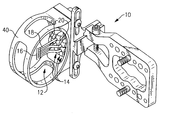
FIG. 1 shows a perspective view of one exemplary embodiment of a bow sight 10 in accordance with the present invention. The bow sight 10 includes a set of pins 12 in multiple tracks 14 (here, three pin tracks) with the pin heads 16 aligned in a plane. The bow sight 10 has two straight pins 18 and four dogleg pins 20. The dogleg pins 20 in the rear track extend forward and the dogleg pins 20 in the forward track extend rearward into alignment with the straight pins 18. In the exemplary embodiment of the bow sight 10, the pin heads are also aligned with a common vertical axis. The configuration of the dogleg pins 20 enable the pin heads 16 to remain in alignment even though the bow twists when an archer draws the string.
FIGS. 2-5 show an exemplary embodiment of a dogleg pin 20 in accordance with the present invention. The pin 20 is referred to as a “dogleg” pin because the pin has a base 22 that is aligned with an axis 24 and a pin head 26 that is offset from that axis 24. The pin head 26 is offset by an amount such that the pin head 26 will align in a common axis with the pin heads 16 from all other pins when installed in the bow sight 10.
FIGS. 6-8 show an exemplary embodiment of a straight pin 18 in accordance with the present invention. The straight pin 18 is straight because the pin 18 has a base 30 that has an axis 32 that is aligned with the pin head 34. As shown in FIG. 1, the straight pin 18 is positioned in the center track of the multiple tracks 14 of the bow sight 10.
As shown in FIG. 5, the pins 18 and 20 have apertures 28 that are each adapted to receive a fiber optic element (not shown). The apertures 28 in each of the pins 18 and 20 of the exemplary embodiment are adapted to align the fiber optic elements in a common plane such that each fiber optic element appears to have the same degree of brightness to an archer in a sight picture.
FIGS. 9 and 10 show the pin guard 40 of the exemplary bow sight 10 of FIG. 1 in accordance with the present invention. As shown in FIG. 10, the pin guard 40 is circular. As explained above, the circular pin guard 40 forms an integral portion of the sight picture for an archer using the bow sight 10 of the present invention. The inventor discovered that the human mind works in such a manner that it is natural for an archer to align elements (such as pins) within a circular pin guard. Thus the circular pin guard 40 forms a circular viewing aperture and defines an integral portion of the sight picture to make it easier for an archer to obtain a proper sight picture. In a preferred embodiment, the pin guard 40 may be colored about its periphery to further enable the archer to distinguish the pin guard 40 form the background that is visible around the target, and to assist the archer in forming a proper sight picture. The pin guard 40 may include any color such as bright orange color, however, it is understood that any color may be used that will assist in making the pin guard 40 in being distinguishable from a background. The color may be applied in any manner such as by, for example, a sticker or paint, or the like and still form a part of the present invention.
While the bow sight 10 described above has three tracks 14, it is understood by those of ordinary skill in the art that a bow sight with any number of multiple tracks is within the scope of this invention. Additionally, while the bow sight 10 described above has a straight pin 18 positioned in the center track, one of ordinary skill in the art understands that a straight pin may be positioned in any track. As long as a bow sight has a pin with a dogleg configuration and all the pin heads are aligned with each other, those of ordinary skill in the art understand that such a bow sight falls within the scope of this invention.
While this invention has been described with reference to the specific embodiments outlined above, many alternatives, modifications and variations are and will be apparent to those skilled in the art. Accordingly, the preferred embodiments described above are illustrative and are not limiting. Various changes may be made without departing from the spirit and scope of the invention.

Claims (14)

What is claimed:
1. A bow sight comprising:
a pin holder having a plurality of pin tracks spaced from one another in a fore-and-aft direction; and a plurality of pins distributed among said plurality of pin tracks, with at least one of said pins being adjustably mounted in each of said tracks, wherein each of said pins has a proximal end member that is adjustably mounted in an associated one of said pin tracks, and a distal end portion thereof that extends distally away from said pin holder, each said distal portion having a pin head disposed at an end thereof; and wherein the pins that are mounted in at least one of said pin tracks have an offset between the distal end portion and the proximal end member thereof, such that the pin heads of all the pins are aligned along one common vertical axis.
2. The bow sight of claim 1, wherein each of said plurality of said pins includes a base that is slidably mounted in a respective one of said plurality of pin tracks.
3. The bow sight of claim 1, wherein at least one of said plurality of pins is shaped in a dog-leg.
4. The bow sight of claim 3, wherein another one of said plurality of pins is straight with no offset.
5. The bow sight of claim 1, wherein at least one of said plurality of pins further includes an aperture passing transversely through its pin head and a fiber optic element mounted in said aperture.
6. The bow sight of claim 5, further comprising another of said plurality of pins including an aperture transversely through its pin head and another fiber optic element mounted in said aperture of said other pin and wherein said fiber optic elements have ends that are axially aligned with a plane that is approximately aligned with an archer's sight picture.
7. The bow sight of claim 1 wherein the at least one pin in a respective one of said pin tracks has an offset that is different from the at least one pin in each of the other pin tracks.
8. The bow sight of claim 1 wherein there are three of said pin tracks.
9. The bow sight of claim 1 wherein the at least one pin mounted in one of the pin tracks has an offset in one direction, and the at least one pin in another of said pin tracks has an offset in an opposite direction.
10. A bow sight through which an archer aims at a target situated in a visual background, comprising:
a pin holder having a plurality of pin tracks;
a plurality of pins distributed among said plurality of pin tracks, each said pin having a proximal end member that is adjustably mounted in one of said pin tracks and a distal portion that extends in a direction away from said pin holder, each said pin having a pin head at the distal end thereof; said distal ends of at least some of said pins being offset with respect to their proximal end member such that the heads of all of said pins lie along a common vertical axis; and
a pin guard attached onto said pin holder and surrounding said plurality of pins and forming a closed visual aperture around said plurality of pins to define a sight picture for the archer, the pin guard having a front surface facing the archer, and said front surface of said pin guard having a predetermined distinctive color applied thereto, the color being adapted to distinguish the pin visual aperture of the pin guard from said visual background.
11. The bow sight of claim 10, wherein said pin guard is substantially circular.
12. The bow sight of claim 10, wherein the distinctive color applied onto the front surface of said pin guard is a bright color.
13. The bow sight of claim 12, wherein said bright color is a high-visibility orange.
14. The bow sight of claim 12, wherein said distinctive color is applied around the entire front surface of said pin guard such that a ring of said distinctive color surrounds the entire periphery of said sight picture.
US09/768,467 2000-01-26 2001-01-25 Solo plane pin head bow sight Expired - Fee Related US6508005B2 (en)

Priority Applications (2)

Application Number Priority Date Filing Date Title
US09/768,467 US6508005B2 (en) 2000-01-26 2001-01-25 Solo plane pin head bow sight
US10/348,473 US20030110648A1 (en) 2000-01-26 2003-01-21 Solo plane pin head bow sight with improved visibility

Applications Claiming Priority (2)

Application Number Priority Date Filing Date Title
US17814300P 2000-01-26 2000-01-26
US09/768,467 US6508005B2 (en) 2000-01-26 2001-01-25 Solo plane pin head bow sight

Related Child Applications (1)

Application Number Title Priority Date Filing Date
US10/348,473 Continuation-In-Part US20030110648A1 (en) 2000-01-26 2003-01-21 Solo plane pin head bow sight with improved visibility

Publications (2)

Publication Number Publication Date
US20010032393A1 US20010032393A1 (en) 2001-10-25
US6508005B2 true US6508005B2 (en) 2003-01-21

Family

ID=26874021

Family Applications (1)

Application Number Title Priority Date Filing Date
US09/768,467 Expired - Fee Related US6508005B2 (en) 2000-01-26 2001-01-25 Solo plane pin head bow sight

Country Status (1)

Country Link
US (1) US6508005B2 (en)

Cited By (15)

* Cited by examiner, † Cited by third party
Publication number Priority date Publication date Assignee Title
US20030208916A1 (en) * 2000-06-30 2003-11-13 Rager Christopher A. Bow sight having vertical, in-line sight pins, and methods
US20040031162A1 (en) * 2000-06-30 2004-02-19 Trophy Ridge, Llc Bow sight with fiber optics
US6701632B2 (en) * 2001-01-17 2004-03-09 Donald J Henry HTM direct drive and positive positioning cross slide and pin housing system
US20040088871A1 (en) * 2001-11-20 2004-05-13 Afshari Abbas Ben Fixed pin bow sight
US6802129B1 (en) * 2002-09-06 2004-10-12 Wirth Reinhold F Archery sight, an optic assembly, and optic adjustment mechanisms for use in an archery sight
US20050241163A1 (en) * 2004-04-28 2005-11-03 Algurt Cudney Sight for armament
US20060096150A1 (en) * 2004-11-11 2006-05-11 Carolina Archery Products Inc. Products and processes for archery and firearm sights
US20070220761A1 (en) * 2006-03-24 2007-09-27 H-T Archery Products, Llc Archery bow sights and archery bows including same
US7610686B1 (en) 2007-01-13 2009-11-03 Gregory E. Summers Supporting bowsights
US20090278404A1 (en) * 2008-05-08 2009-11-12 Infineon Technologies Ag Circuit Arrangement and System for Use in a Motor Vehicle
US20100018513A1 (en) * 2008-07-22 2010-01-28 Scaniffe Michael J Compound bow accessory
US8171648B2 (en) 2008-10-16 2012-05-08 Gregory E. Summers Producing and using archery sights
US20130118019A1 (en) * 2011-05-05 2013-05-16 Rein-O-King, LLC d/b/a Tactical Archery Systems Bow Sight with Light Gathering Point Shaped Pins, Illuminated Yardage Indicia, and Individual Pin Micro-Adjustment
US9261323B2 (en) 2011-01-28 2016-02-16 Copper John Corporation Bowstring release having a safety device
US10145646B2 (en) 2014-11-13 2018-12-04 Scott Archery Llc Archery bowstring release enabling sensitivity adjustment

Families Citing this family (2)

* Cited by examiner, † Cited by third party
Publication number Priority date Publication date Assignee Title
US20050193575A1 (en) * 2004-03-05 2005-09-08 Copper John Corporation Bow sight and sight cover assembly
US7814669B2 (en) * 2007-06-18 2010-10-19 Kingsbury Klint M Multi-spot adjustable reflex bow sight

Citations (16)

* Cited by examiner, † Cited by third party
Publication number Priority date Publication date Assignee Title
US3310875A (en) * 1964-07-15 1967-03-28 Robert J Kowalski Archery bow sight
US3747222A (en) * 1971-01-22 1973-07-24 A Benoit Bow sight
US4580349A (en) * 1985-05-07 1986-04-08 Webb Leamon G Range finder for a bow
US4928394A (en) * 1989-04-03 1990-05-29 Sherman James R Sight for archery bow
US5080084A (en) * 1990-10-19 1992-01-14 Kendall Robert M Light saver peep sight for archers
US5168631A (en) * 1991-05-20 1992-12-08 Sherman James R Sight
US5201124A (en) * 1992-01-28 1993-04-13 Sherman James R Illuminated archery sight pin
US5220907A (en) * 1992-05-19 1993-06-22 Lonsdale James K Archery bow sight
US5228204A (en) * 1992-09-28 1993-07-20 Bahram Khoshnood Archery bow sight having individually adjustable sight pins
US5560113A (en) * 1994-06-27 1996-10-01 New Archery Products Corp. Bowsight
US5685081A (en) * 1995-09-08 1997-11-11 Winegar; Mike Aiming device for use on archery bows
US5864958A (en) * 1997-02-10 1999-02-02 Bruno Kolb Rear sight for bow
US6000141A (en) * 1997-12-19 1999-12-14 Scout Mountain Equipment, Inc. Archery bow sight
US20020083602A1 (en) * 2001-01-02 2002-07-04 Slates Scott O. Fiber optic pin sights for bow
US6418633B1 (en) * 2000-06-30 2002-07-16 Trophy Ridge, Llc Vertical in-line bow sight
US6430822B1 (en) * 2000-11-30 2002-08-13 Toxonics Manufacturing, Inc. Archery bow sight mount with horizontal adjustment of the sight

Patent Citations (16)

* Cited by examiner, † Cited by third party
Publication number Priority date Publication date Assignee Title
US3310875A (en) * 1964-07-15 1967-03-28 Robert J Kowalski Archery bow sight
US3747222A (en) * 1971-01-22 1973-07-24 A Benoit Bow sight
US4580349A (en) * 1985-05-07 1986-04-08 Webb Leamon G Range finder for a bow
US4928394A (en) * 1989-04-03 1990-05-29 Sherman James R Sight for archery bow
US5080084A (en) * 1990-10-19 1992-01-14 Kendall Robert M Light saver peep sight for archers
US5168631A (en) * 1991-05-20 1992-12-08 Sherman James R Sight
US5201124A (en) * 1992-01-28 1993-04-13 Sherman James R Illuminated archery sight pin
US5220907A (en) * 1992-05-19 1993-06-22 Lonsdale James K Archery bow sight
US5228204A (en) * 1992-09-28 1993-07-20 Bahram Khoshnood Archery bow sight having individually adjustable sight pins
US5560113A (en) * 1994-06-27 1996-10-01 New Archery Products Corp. Bowsight
US5685081A (en) * 1995-09-08 1997-11-11 Winegar; Mike Aiming device for use on archery bows
US5864958A (en) * 1997-02-10 1999-02-02 Bruno Kolb Rear sight for bow
US6000141A (en) * 1997-12-19 1999-12-14 Scout Mountain Equipment, Inc. Archery bow sight
US6418633B1 (en) * 2000-06-30 2002-07-16 Trophy Ridge, Llc Vertical in-line bow sight
US6430822B1 (en) * 2000-11-30 2002-08-13 Toxonics Manufacturing, Inc. Archery bow sight mount with horizontal adjustment of the sight
US20020083602A1 (en) * 2001-01-02 2002-07-04 Slates Scott O. Fiber optic pin sights for bow

Cited By (28)

* Cited by examiner, † Cited by third party
Publication number Priority date Publication date Assignee Title
US7549230B2 (en) 2000-06-30 2009-06-23 Bear Archery, Inc. Bow sight with fiber optics
US20040031162A1 (en) * 2000-06-30 2004-02-19 Trophy Ridge, Llc Bow sight with fiber optics
US20080115373A1 (en) * 2000-06-30 2008-05-22 Bear Archery, Inc. Bow sight with fiber optics
US6892462B2 (en) * 2000-06-30 2005-05-17 Trophy Ridge, Llc Vertical in-line bow sight
US7343686B2 (en) 2000-06-30 2008-03-18 Bear Archery, Inc. Bow sight with fiber optics
US7036234B2 (en) * 2000-06-30 2006-05-02 Trophy Ridge, Llc Bow sight having vertical, in-line sight pins, and methods
US20030208916A1 (en) * 2000-06-30 2003-11-13 Rager Christopher A. Bow sight having vertical, in-line sight pins, and methods
US7159325B2 (en) 2000-06-30 2007-01-09 Trophy Ridge, Llc Bow sight with fiber optics
US20070157480A1 (en) * 2000-06-30 2007-07-12 Trophy Ridge, Llc Bow sight with fiber optics
US6701632B2 (en) * 2001-01-17 2004-03-09 Donald J Henry HTM direct drive and positive positioning cross slide and pin housing system
US20040088871A1 (en) * 2001-11-20 2004-05-13 Afshari Abbas Ben Fixed pin bow sight
US7100291B2 (en) * 2001-11-20 2006-09-05 Abbas Ben Afshari Fixed pin bow sight
US6802129B1 (en) * 2002-09-06 2004-10-12 Wirth Reinhold F Archery sight, an optic assembly, and optic adjustment mechanisms for use in an archery sight
US20050241163A1 (en) * 2004-04-28 2005-11-03 Algurt Cudney Sight for armament
US7308891B2 (en) 2004-11-11 2007-12-18 Sop Services, Inc. Products and processes for archery and firearm sights
US20060096150A1 (en) * 2004-11-11 2006-05-11 Carolina Archery Products Inc. Products and processes for archery and firearm sights
US7328515B2 (en) 2006-03-24 2008-02-12 H-T Archery Products Llc Archery bow sights and archery bows including same
US20070220761A1 (en) * 2006-03-24 2007-09-27 H-T Archery Products, Llc Archery bow sights and archery bows including same
US7610686B1 (en) 2007-01-13 2009-11-03 Gregory E. Summers Supporting bowsights
US20090278404A1 (en) * 2008-05-08 2009-11-12 Infineon Technologies Ag Circuit Arrangement and System for Use in a Motor Vehicle
US20100018513A1 (en) * 2008-07-22 2010-01-28 Scaniffe Michael J Compound bow accessory
US7997261B2 (en) * 2008-07-22 2011-08-16 Scaniffe Michael J Compound bow accessory
US8171648B2 (en) 2008-10-16 2012-05-08 Gregory E. Summers Producing and using archery sights
US8176644B1 (en) 2008-10-16 2012-05-15 Gregory E. Summers Producing and using archery sights
US9261323B2 (en) 2011-01-28 2016-02-16 Copper John Corporation Bowstring release having a safety device
US20130118019A1 (en) * 2011-05-05 2013-05-16 Rein-O-King, LLC d/b/a Tactical Archery Systems Bow Sight with Light Gathering Point Shaped Pins, Illuminated Yardage Indicia, and Individual Pin Micro-Adjustment
US8776386B2 (en) * 2011-05-05 2014-07-15 Klint McLean KINGSBURY Bow sight with light gathering point shaped pins, illuminated yardage indicia, and individual pin micro-adjustment
US10145646B2 (en) 2014-11-13 2018-12-04 Scott Archery Llc Archery bowstring release enabling sensitivity adjustment

Also Published As

Publication number Publication date
US20010032393A1 (en) 2001-10-25

Similar Documents

Publication Publication Date Title
US6508005B2 (en) Solo plane pin head bow sight
US6000141A (en) Archery bow sight
US5996569A (en) Transparent rear bow sight
US7373723B1 (en) Bow sight
US7159325B2 (en) Bow sight with fiber optics
US7226362B1 (en) Golf club head including alignment device
US7685760B1 (en) Paintball marker sight apparatus
US5862603A (en) Sighting indicia
US20040244211A1 (en) Illuminated sight pin
US4961264A (en) Restraint alignment assembly for use with a string-mounted peepsight
US20070004524A1 (en) Customizable golf club alignment system
US7200943B2 (en) Bow sight with vertically aligned pins
US5086567A (en) Archery bow sight reticle with multiple fixed aiming points
US5862618A (en) Gun sight for sighting moving targets
US7266896B1 (en) String-mounted bow sight
US3548504A (en) Sighting device for establishing a line of sight
JPS6069498A (en) Sighting system
US20050150119A1 (en) Sight and sight pins for archery bow
JPH04276274A (en) Golf club with matching mark
US6868615B2 (en) Telescopic weapon aiming system
US6574900B1 (en) O'Malley's weapon aiming system
US8225517B2 (en) Sighting system and range finder for an archery bow
US7308891B2 (en) Products and processes for archery and firearm sights
US20030019118A1 (en) Transparent rear bow sights
US7231721B2 (en) Archery laser arrow

Legal Events

Date Code Title Description
AS Assignment

Owner name: COPPER JOHN CORPORATION, NEW YORK

Free format text: ASSIGNMENT OF ASSIGNORS INTEREST;ASSIGNOR:SPRINGER, ERIC C.;REEL/FRAME:011487/0109

Effective date: 20010119

CC Certificate of correction
FEPP Fee payment procedure

Free format text: PAYOR NUMBER ASSIGNED (ORIGINAL EVENT CODE: ASPN); ENTITY STATUS OF PATENT OWNER: SMALL ENTITY

FPAY Fee payment

Year of fee payment: 4

FPAY Fee payment

Year of fee payment: 8

REMI Maintenance fee reminder mailed
LAPS Lapse for failure to pay maintenance fees
STCH Information on status: patent discontinuation

Free format text: PATENT EXPIRED DUE TO NONPAYMENT OF MAINTENANCE FEES UNDER 37 CFR 1.362

FP Lapsed due to failure to pay maintenance fee

Effective date: 20150121