US6500054B1 - Chemical-mechanical polishing pad conditioner - Google Patents
Chemical-mechanical polishing pad conditioner Download PDFInfo
- Publication number
- US6500054B1 US6500054B1 US09/590,576 US59057600A US6500054B1 US 6500054 B1 US6500054 B1 US 6500054B1 US 59057600 A US59057600 A US 59057600A US 6500054 B1 US6500054 B1 US 6500054B1
- Authority
- US
- United States
- Prior art keywords
- polishing pad
- conditioner
- section
- per unit
- chemical
- Prior art date
- Legal status (The legal status is an assumption and is not a legal conclusion. Google has not performed a legal analysis and makes no representation as to the accuracy of the status listed.)
- Expired - Fee Related
Links
- 238000005498 polishing Methods 0.000 title claims abstract description 159
- 230000003750 conditioning effect Effects 0.000 claims abstract description 84
- 238000000034 method Methods 0.000 claims abstract description 18
- 230000007704 transition Effects 0.000 claims description 11
- 229910003460 diamond Inorganic materials 0.000 claims description 2
- 239000010432 diamond Substances 0.000 claims description 2
- 230000007246 mechanism Effects 0.000 abstract description 5
- 239000002002 slurry Substances 0.000 description 19
- 239000002245 particle Substances 0.000 description 10
- 230000008569 process Effects 0.000 description 9
- 239000000463 material Substances 0.000 description 5
- VYPSYNLAJGMNEJ-UHFFFAOYSA-N Silicium dioxide Chemical compound O=[Si]=O VYPSYNLAJGMNEJ-UHFFFAOYSA-N 0.000 description 4
- 239000004065 semiconductor Substances 0.000 description 4
- 230000001143 conditioned effect Effects 0.000 description 3
- 230000009471 action Effects 0.000 description 2
- 239000007788 liquid Substances 0.000 description 2
- 239000002184 metal Substances 0.000 description 2
- 239000004576 sand Substances 0.000 description 2
- 239000000126 substance Substances 0.000 description 2
- 239000003082 abrasive agent Substances 0.000 description 1
- 238000013459 approach Methods 0.000 description 1
- 230000009286 beneficial effect Effects 0.000 description 1
- 238000010276 construction Methods 0.000 description 1
- 238000005516 engineering process Methods 0.000 description 1
- 239000011344 liquid material Substances 0.000 description 1
- 238000004519 manufacturing process Methods 0.000 description 1
- 238000012986 modification Methods 0.000 description 1
- 230000004048 modification Effects 0.000 description 1
- 230000003287 optical effect Effects 0.000 description 1
- 238000000206 photolithography Methods 0.000 description 1
- 238000007517 polishing process Methods 0.000 description 1
- 238000000926 separation method Methods 0.000 description 1
- 235000012239 silicon dioxide Nutrition 0.000 description 1
- 239000000377 silicon dioxide Substances 0.000 description 1
Images


Classifications
-
- B—PERFORMING OPERATIONS; TRANSPORTING
- B24—GRINDING; POLISHING
- B24B—MACHINES, DEVICES, OR PROCESSES FOR GRINDING OR POLISHING; DRESSING OR CONDITIONING OF ABRADING SURFACES; FEEDING OF GRINDING, POLISHING, OR LAPPING AGENTS
- B24B53/00—Devices or means for dressing or conditioning abrasive surfaces
- B24B53/017—Devices or means for dressing, cleaning or otherwise conditioning lapping tools
-
- B—PERFORMING OPERATIONS; TRANSPORTING
- B24—GRINDING; POLISHING
- B24B—MACHINES, DEVICES, OR PROCESSES FOR GRINDING OR POLISHING; DRESSING OR CONDITIONING OF ABRADING SURFACES; FEEDING OF GRINDING, POLISHING, OR LAPPING AGENTS
- B24B37/00—Lapping machines or devices; Accessories
- B24B37/11—Lapping tools
- B24B37/20—Lapping pads for working plane surfaces
- B24B37/26—Lapping pads for working plane surfaces characterised by the shape of the lapping pad surface, e.g. grooved
-
- B—PERFORMING OPERATIONS; TRANSPORTING
- B24—GRINDING; POLISHING
- B24B—MACHINES, DEVICES, OR PROCESSES FOR GRINDING OR POLISHING; DRESSING OR CONDITIONING OF ABRADING SURFACES; FEEDING OF GRINDING, POLISHING, OR LAPPING AGENTS
- B24B53/00—Devices or means for dressing or conditioning abrasive surfaces
- B24B53/12—Dressing tools; Holders therefor
Definitions
- the present invention relates generally to semiconductor manufacturing and, more specifically, to the conditioning of polishing pads used for chemical-mechanical polishing (CMP).
- CMP chemical-mechanical polishing
- CMP Chemical-Mechanical Polishing
- CMP is useful for planarizing intermetal dielectric layers of silicon dioxide or for removing portions of conductive layers within integrated circuit devices.
- Non-planar dielectric surfaces may interfere with the optical resolution of subsequent photolithography processing steps, making it extremely difficult to print high-resolution lines.
- the application of a second metal layer over an intermetal dielectric layer having large step heights can result in inadequate metal coverage, and ultimately in an open circuit.
- FIG. 1 illustrates an exemplary linear CMP process.
- a semiconductor wafer 20 is typically held face down against a flat polishing pad 22 that has been coated with the slurry (not shown) and that moves relative to wafer 20 along arrow A.
- a rectangular conditioning pad 26 is used to condition polishing pad 22 continuously as wafer 20 is polished.
- semiconductor wafer 20 is typically held face down and rotated along arrow C against a flat polishing pad 24 that has been coated with the slurry and that rotates along arrow B. Both wafer 20 and pad 24 are typically rotated relative to each other. Also shown in FIG. 2 are a first reference location 32 on polishing pad 24 and a second reference location 30 on polishing pad 24 located radially inward of location 32 .
- rectangular conditioning pad 26 is used to condition polishing pad 24 continuously as wafer 20 is polished in the rotary CMP process. In both the linear and rotary CMP processes, the abrasive polishing process continues until the surface of wafer 20 contacting polishing pad 22 or 24 is substantially planar.
- the motion of wafer 20 with respect to polishing pad 22 , 24 and the force applied to hold wafer 20 against the pad adds mechanical energy to the system that helps remove the wafer surface material.
- the process of supplying fresh chemical liquid and removing spent chemical liquid helps remove material from the wafer surface. Uniform removal of material from the surface of wafer 20 is pursued by adjusting a number of variables, such as the pad velocity with respect to the wafer surface, the force applied between the pad and the wafer, and the slurry composition and flow.
- polishing pad 22 , 24 is periodically mechanically scored or “conditioned.”
- Conditioning pad 26 removes the build-up on polishing pad 22 , 24 and roughens the surface of polishing pad 22 , 24 .
- Different approaches to conditioning may be required depending on the hardness of the pad surface and the particular slurry used for polishing. Further, conditioning may be performed by a conditioning apparatus in a discrete conditioning step or during wafer polishing depending on the specific conditioning process and apparatus used.
- FIGS. 1 and 2 both show rectangular conditioning pad 26 that may be used to condition polishing pad 22 , 24 continuously as wafer 20 is polished.
- the polishing pad-and-slurry combination may be envisioned as a piece of sandpaper in which the slurry acts as the sand and the polishing pad acts as the paper on which the sand is mounted.
- the slurry may have different particle sizes, with larger particles providing more grinding of the wafer surface than smaller particles, similar to the difference between larger and smaller grit sandpaper. The more slurry held against the wafer surface or greater particle size of the slurry, the more grinding that may occur.
- Grooves in polishing pad 22 , 24 drain the slurry away from the surface of the pad. Slurry in the grooves is thus ineffective or less effective at grinding than slurry on the surface of the pad.
- the shape and volume of the grooves per unit area of polishing pad 22 , 24 therefore control to some degree the amount of polishing. For example, larger grooves not only take more slurry away from the surface, but also may completely or partially trap larger particles. Small grooves that are unable to trap large slurry particles leave the large particles in contact with wafer 20 , providing more grinding than parts of polishing pad 22 , 24 where the grooves are large enough to allow such particles to be trapped in the grooves. Intermediate size grooves may only partially trap the particles, leaving portions of the large particles protruding and providing less polishing than where only small grooves are present, but more so than where large grooves are present. The depth of the grooves may further control how much of the slurry is drained away, deeper grooves providing areas with less polishing capability than in shallower grooves.
- polishing rate and uniformity of the CMP process may be greatly affected by the characteristics of the polishing pad surface, which can make the slurry more or less effective.
- the ability to optimize the pad surface during conditioning is therefore highly desirable.
- the present invention provides a chemical-mechanical polishing pad conditioner comprising a non-uniform conditioning surface having a plurality of conditioning elements and at least a first section and a second section.
- the first section has a first cutting volume per unit width that is greater than the second cutting volume per unit width of the second section.
- the first section may include at least one first conditioning element having a first projected width whereas the second section includes at least one second conditioning element having a second projected width that differs from the first projected width.
- the first section may also or instead have a first plurality of conditioning elements with a first density whereas the second section has a second plurality of conditioning elements with a second density that is different from the first density.
- the first section may also or instead have at least one conditioning element with a first cutting depth whereas the second section has at least one conditioning element with a second cutting depth different from the first depth.
- the conditioner may be adapted for use in a linear or rotary CMP operation, and may be rectangular or may be a roller-type conditioner.
- the non-uniform conditioning surface may be designed to compensate for a difference in relative velocity of the polishing pad at a radial-inward location as compared to a radial-outward location.
- the conditioner may further comprise a third, transition section between the first section and the second section.
- the third section has a third cutting volume per unit width intermediate the first and second cutting volumes per unit width.
- the third section also has a gradual transition in cutting volume per unit width between the first and second cutting volumes per unit width.
- the conditioner may be an element in a chemical-mechanical polishing tool comprising a polishing pad, the conditioner, and a mechanism for moving the polishing pad relative to the conditioner.
- the mechanism may further be adapted to move the polishing pad relative to the conditioner in a linear or rotary manner.
- the conditioner may be used to perform a method for providing uniform conditioning of a chemical-mechanical polishing pad.
- the method first comprises the step of identifying at least a first region of the polishing pad that requires a different volume of material removed by the conditioner than a second region of the polishing pad.
- the conditioner is provided with a non-uniform conditioning surface having a first section with a first cutting volume per unit width positioned to contact the first region of the polishing pad and a second section with a second cutting volume per unit width positioned to contact the second region of the polishing pad.
- the conditioner is then used to condition the polishing pad.
- the invention also comprises a chemical-mechanical polishing pad that results from use of the conditioner of this invention.
- a pad comprises a non-uniform polishing surface having a plurality of grooves and at least a first region and a second region.
- the first region has a first groove volume per unit area that differs from a second groove volume per unit area of the second region.
- FIG. 1 depicts a plan view of a typical linear CMP operation
- FIG. 2 depicts a plan view of a typical rotary CMP operation
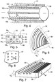
- FIG. 3 depicts a side view of an exemplary rectangular pad conditioner of the present invention
- FIG. 4 depicts a perspective view of an exemplary cylindrical roller pad conditioner of the present invention
- FIG. 5 depicts a plan view of an exemplary conditioner showing various geometries for conditioning elements with equivalent projected widths
- FIG. 6 depicts a plan view of a portion of a rotary polishing pad created by use of the conditioner of the present invention
- FIG. 7 depicts a partial cross-section perspective view of a portion of a linear polishing pad created by use of a conditioner of the present invention
- FIG. 8 depicts a plan view of a portion of a polishing pad created by use of a roller-type conditioner of the present invention for which the conditioner and polishing pad are traveling at approximately the same speed;
- FIG. 9 depicts a plan view of a portion of a polishing pad created by use of a roller-type conditioner of the present invention for which the conditioner is traveling at a speed slower than the conditioning pad;
- FIG. 10 depicts a perspective view of an exemplary cylindrical roller pad conditioner of the present invention showing sections having different row densities.
- FIG. 3 depicts an exemplary chemical-mechanical polishing pad conditioner 40 having a non-uniform conditioning surface 42 comprising a plurality of conditioning elements 44 .
- Non-uniform surface 42 comprises three distinct sections 46 , 48 , and 50 .
- Conditioning elements 44 a in section 46 have a width w a that is greater than the width w c , of conditioning elements 44 c in section 50 .
- Conditioning elements 44 b in section 48 have a width w b that is intermediate widths w a and w c .
- the conditioning elements may have any cross-sectional geometry known in the art, as shown in FIG. 5, including but not limited to: a square 60 ; an ellipse or oval 62 ; a rectangle 64 a, 64 b with the longer side facing the cutting plane ( 64 a ) or the shorter side facing the cutting plane ( 64 b ); a circle 66 ; a triangle 68 , a diamond 70 ; or any type of polygon 72 .
- Every cross-sectional geometry has a “projected width,” however, onto imaginary plane I. This projected width is essentially what is seen from a side view of the conditioner 40 , such as is shown in FIG. 3 .
- each of the conditioning elements may have the same projected width w p .
- conditioner 40 is shown for illustrative purposes in FIG. 5 with a plurality of different shaped studs, typically a conditioner will contain only a single type of stud. Multiple shapes may be used on a single conditioner, however, if desired.
- the group of conditioning elements 44 c in section 50 can also be said to have a density that is greater than the group of elements 44 a in section 46 .
- “Density” refers to the number of projected elements per unit width. A unit width is measured along arrow X in the cross section of FIG. 3 .
- conditioner 40 may have several rows of elements as shown in FIG. 5 from an underside view. The elements of each row may directly align with the elements of the other rows as viewed from plane I, such as the elements in the rows 80 and 84 , or the elements of one row may fill the gaps between elements of another row, as the elements of row 82 fill in the gaps in rows 80 and 84 .
- the number of “projected elements” is the number of elements that are visible from a side view. Thus, as shown in FIG. 5, there are five projected elements, although three of the elements are aligned in rows 80 and 84 and two of the elements are in row 82 .
- the conditioning elements 44 c in section 50 are shown with a greater cutting depth than the cutting depth of elements 44 a .“Cutting depth” refers to the depth that the conditioning element penetrates the polishing pad. The degree to which each element penetrates the polishing pad is controlled by the amount of pressure exerted on the conditioning pad as it contacts the polishing pad. Generally, however, elements that protrude a longer distance from conditioner body 41 have a longer cutting depth. Thus, elements 44 c that protrude a depth of d c , have a longer cutting depth than elements 44 a that protrude a depth d a from body 41 . Elements 44 b that protrude a depth d b have an intermediate cutting depth between the cutting depths d a and d c of elements 44 a and 44 c, respectively.
- the differences in depth, density, and projected width per conditioning element, or some combination of those geometric features, provide each region with a different cutting volume per unit width.
- the term “cutting volume per unit width” relates to the volume of the polishing pad that is removed by the conditioner per each unit width of the conditioner. For example, in FIG. 3, where each conditioning element 44 comprises a stud that protrudes from body 41 of conditioning pad 40 , the cutting volume per unit width equals the total number of studs projected onto a single row times the projected width of each stud times the cutting depth of each stud, divided by the length of the region.
- a combination of larger element projected width, greater density, and greater cutting depth may be used to provide the greater cutting volume per unit width.
- a differential in only one such feature may be used to provide the different cutting volume per unit width.
- a larger element projected width may be offset by a lesser density, or a greater density may be offset by a lesser element projected width.
- Chemical-mechanical polishing pad conditioners of the present invention may be designed for use with either linear CMP operations or rotary CMP operations.
- the non-uniformity may be designed to compensate for a difference in relative velocity between the polishing pad and the wafer at a radial inward location as compared to a radial outward location.
- location 30 on polishing pad 24 is located radially inward of location 32 .
- the relative velocity between polishing pad 24 and wafer 20 at outward location 32 is greater than at inward location 30 .
- the grinding action at location 32 of polishing pad 24 may be greater than at location 30 .
- conditioner 40 provides such a configuration if section 50 is aligned with location 30 and section 46 is aligned with location 32 . It may be further desirable for section 48 to comprise a gradual transition between sections 50 and 46 , or for there to be a continuum between a smallest conditioning element 44 c at an inner location and a largest conditioning element 44 a at a radial outward location.
- the non-uniformity in conditioner 40 may be tailored to compensate for a non-uniformity in polishing pad wear or tool application pressure.
- the wear of the polishing pad may be different or the pressure applied between the pad and the wafer may be different at the edges than in the center.
- a different cutting volume per unit width may be needed on the edges than in the center to keep the polishing action of the pad uniform.
- FIG. 3 depicts conditioner 40 having a rectangular shape
- the shape may be any shape as is known in the art.
- the conditioner may be a cylindrical roller-type conditioner 52 that is adapted to be rotated about an axis Z, as shown in FIG. 4 .
- Such a conditioner may be used with linear or rotary CMP operations and is positioned similar to a rectangular conditioner.
- the cylindrical roller shape allows the roller to be rotated about axis Z, however, to increase or decrease the relative velocity between the polishing pad and the conditioner.
- Roller-type conditioner 52 may be mounted on a shaft (not shown) coaxial with axis Z, which may be rotated any mechanism known in the art for rotating a shaft.
- the depicted conditioners may be used with any chemical-mechanical polishing tools known in the art, such as are depicted in FIGS. 1 and 2, but are not limited to such configurations. Any tool having a polishing pad and a mechanism for moving the polishing pad relative to the pad conditioner may be used with the conditioning pad structures illustrated and described. Tools for use with cylindrical roller conditioning pads, such as shown in FIG. 4, further include structure for revolving the conditioning pad about axis Z, as is known in the art.
- the depicted conditioners may be used to condition a chemical-mechanical polishing pad.
- the method of providing such conditioning comprises identifying at least a first region of the polishing pad that requires a different groove volume per unit area than a second region of the polishing pad. For example, a first region may require wider or deeper grooves than a second region of the polishing pad.
- the different velocities at radial inner and outer locations on the pad necessitate a different groove volume per unit area in inner and outer sections of the polishing pad.
- the method comprises constructing a conditioner with a non-uniform conditioning surface having a first section tailored with a first cutting volume per unit width aligned with the first region of the polishing pad and a second section tailored with a second cutting volume per unit width aligned with the second region, in accordance with the structures described above.
- the conditioning pad is such that a first section is tailored to condition the first region of the polishing pad more than a second section conditions the second region.
- the conditioner so provided is then used to condition the polishing pad.
- conditioners comprising any materials of construction known in the art, conditioners having conditioning elements of any size and cross-sectional geometry, and conditioners having any density that is functional to provide the desired degree of conditioning.
- the pie-shaped portion of rotary polishing pad 90 conditioned with a conditioner as described above may have a corresponding groove volume per unit area in one region that is different than in another.
- the region 92 has a greater density of grooves than the region 94 .
- Region 94 has a greater groove width w g than region 92 .
- the groove depth d g may also be varied in accordance with the cutting depth of the conditioning elements, as illustrated in the linear polishing pad 96 depicted in FIG. 7, showing grooves 93 a depth d g1 that is greater than the depth d g2 of the grooves 95 .
- the polishing pad may comprise two regions 92 and 94 having a different groove volume per unit area, and may further comprise a third region 98 between regions 92 and 94 having an intermediate groove volume per unit area.
- the third region may provide a gradual transition from the first and second regions.
- a polishing pad 97 conditioned with a roller-type conditioner 52 may have discontinuous, shorter grooves, such as grooves 91 , as shown in FIG. 8, and grooves 99 , as shown in FIG. 9 .
- the length of each groove depends upon the speed of roller-type conditioner 52 relative to the speed of polishing pad 97 at the point of contact between the two surfaces.
- Roller-type conditioner 52 and polishing pad 97 moving at approximately the same speed results in discontinuous grooves 91 that are no longer than approximately conditioning elements 44 that create the grooves, as shown in FIG. 8 .
- Roller-type conditioner 52 moving slower than polishing pad 97 results in elongated, discontinuous grooves 99 .
- Roller-type conditioner 52 moving faster than polishing pad 97 results in elongated grooves with a space s p between discontinuous grooves that is shorter than the space S r between rows 100 of studs 44 on the surface of roller-type conditioner 52 .
- roller-type conditioner 52 shown in FIG. 4 comprises rows 100 of conditioning elements 44 parallel to axis Z that extend from one end of the roller to another
- roller-type conditioners may have patterns of conditioning elements (e.g., studs) that are non-linear, that are different in one longitudinal section as compared to another, that have a different density in one section as compared to another, that do not extend from one end to another, or some combination of such arrangements, just as for non-roller-type conditioners as shown in FIG. 3.
- a roller-type conditioner has the additional parameter, however, of “row density”—the number of rows per circumference. Thus, one longitudinal section may have a greater row density than another section.
- Roller-type conditioners may also have all of the other variations in conditioning element parameters as described relative to non-roller-type conditioners.
- the variations in row density from one section to another, as well as variations in conditioning element width and height or density per unit width provide different cutting volumes per unit width revolution of the roller.
- one revolution of one unit width in one section of the roller may cut a different volume of the conditioning pad than a unit width in another section of the roller.
- roller 53 as shown in FIG. 10 has a first longitudinal section 56 that has nine rows 100 of studs 110 each having a first width and height per the half-circumference shown, whereas second section 58 has only seven rows 101 of studs 111 each having a second width and height per half-circumference.
- section 57 between sections 56 and 58 comprises a transitional section having eight rows 102 of studs 112 each having a third width and height intermediate the first and second width and height.
- Different patterns in one end of a roller-type conditioner versus the other end may be beneficial, for example, on a roller-type conditioner;for use with a rotary polishing pad. Such use may provide different patterns of studs to compensate for the different radial velocity at the inner radius of the pad compared to the outer radius of the pad.
Abstract
A chemical-mechanical polishing (CMP) pad conditioner. The conditioner has a non-uniform conditioning surface with a plurality of conditioning elements. The non-uniform surface comprises a first section having a first cutting volume per unit width and a second section having a second cutting volume per unit width that is different from the first cutting volume per unit width. The difference in cutting volume may be provided by different projected widths of the individual conditioning elements, by a difference in the linear density between the two sections, or by a difference in the cutting depth. A CMP tool comprising a polishing pad, a conditioning pad having the disclosed structure, and a mechanism for moving the polishing pad relative to the pad conditioner is also provided. A method is further provided for uniformly conditioning a CMP pad using a conditioner having the structure described.
Description
The present invention relates generally to semiconductor manufacturing and, more specifically, to the conditioning of polishing pads used for chemical-mechanical polishing (CMP).
Chemical-Mechanical Polishing (CMP) is a key processing technology for fabricating semiconductor chips. Often, after the performance of a processing step, the resulting wafer surface is full of peaks and valleys. Peaks and valleys of subsequent processing steps can build upon one another, creating an uneven surface that may be undesirable for a number of reasons. CMP uses a polishing pad and a slurry of chemically active liquid and abrasive material to grind down the surface of a wafer, thus restoring the planar surface.
In particular, CMP is useful for planarizing intermetal dielectric layers of silicon dioxide or for removing portions of conductive layers within integrated circuit devices. Non-planar dielectric surfaces may interfere with the optical resolution of subsequent photolithography processing steps, making it extremely difficult to print high-resolution lines. The application of a second metal layer over an intermetal dielectric layer having large step heights can result in inadequate metal coverage, and ultimately in an open circuit.
FIG. 1 illustrates an exemplary linear CMP process. A semiconductor wafer 20 is typically held face down against a flat polishing pad 22 that has been coated with the slurry (not shown) and that moves relative to wafer 20 along arrow A. A rectangular conditioning pad 26 is used to condition polishing pad 22 continuously as wafer 20 is polished.
In an exemplary rotary CMP process, shown in FIG. 2, semiconductor wafer 20 is typically held face down and rotated along arrow C against a flat polishing pad 24 that has been coated with the slurry and that rotates along arrow B. Both wafer 20 and pad 24 are typically rotated relative to each other. Also shown in FIG. 2 are a first reference location 32 on polishing pad 24 and a second reference location 30 on polishing pad 24 located radially inward of location 32. As for the linear CMP process, rectangular conditioning pad 26 is used to condition polishing pad 24 continuously as wafer 20 is polished in the rotary CMP process. In both the linear and rotary CMP processes, the abrasive polishing process continues until the surface of wafer 20 contacting polishing pad 22 or 24 is substantially planar.
The motion of wafer 20 with respect to polishing pad 22, 24 and the force applied to hold wafer 20 against the pad adds mechanical energy to the system that helps remove the wafer surface material. In addition, the process of supplying fresh chemical liquid and removing spent chemical liquid helps remove material from the wafer surface. Uniform removal of material from the surface of wafer 20 is pursued by adjusting a number of variables, such as the pad velocity with respect to the wafer surface, the force applied between the pad and the wafer, and the slurry composition and flow.
Over time, the initially rough surface of polishing pad 22, 24 becomes worn and may glaze over due to a build-up of slurry and other deposits on the pad surface. To counteract the glazing and wear, polishing pad 22, 24 is periodically mechanically scored or “conditioned.” Conditioning pad 26 removes the build-up on polishing pad 22, 24 and roughens the surface of polishing pad 22, 24. Different approaches to conditioning may be required depending on the hardness of the pad surface and the particular slurry used for polishing. Further, conditioning may be performed by a conditioning apparatus in a discrete conditioning step or during wafer polishing depending on the specific conditioning process and apparatus used. FIGS. 1 and 2 both show rectangular conditioning pad 26 that may be used to condition polishing pad 22, 24 continuously as wafer 20 is polished.
The polishing pad-and-slurry combination may be envisioned as a piece of sandpaper in which the slurry acts as the sand and the polishing pad acts as the paper on which the sand is mounted. The slurry may have different particle sizes, with larger particles providing more grinding of the wafer surface than smaller particles, similar to the difference between larger and smaller grit sandpaper. The more slurry held against the wafer surface or greater particle size of the slurry, the more grinding that may occur. Grooves in polishing pad 22, 24 drain the slurry away from the surface of the pad. Slurry in the grooves is thus ineffective or less effective at grinding than slurry on the surface of the pad.
The shape and volume of the grooves per unit area of polishing pad 22, 24 therefore control to some degree the amount of polishing. For example, larger grooves not only take more slurry away from the surface, but also may completely or partially trap larger particles. Small grooves that are unable to trap large slurry particles leave the large particles in contact with wafer 20, providing more grinding than parts of polishing pad 22, 24 where the grooves are large enough to allow such particles to be trapped in the grooves. Intermediate size grooves may only partially trap the particles, leaving portions of the large particles protruding and providing less polishing than where only small grooves are present, but more so than where large grooves are present. The depth of the grooves may further control how much of the slurry is drained away, deeper grooves providing areas with less polishing capability than in shallower grooves.
Thus, the polishing rate and uniformity of the CMP process may be greatly affected by the characteristics of the polishing pad surface, which can make the slurry more or less effective. The ability to optimize the pad surface during conditioning is therefore highly desirable.
The present invention provides a chemical-mechanical polishing pad conditioner comprising a non-uniform conditioning surface having a plurality of conditioning elements and at least a first section and a second section. The first section has a first cutting volume per unit width that is greater than the second cutting volume per unit width of the second section. The first section may include at least one first conditioning element having a first projected width whereas the second section includes at least one second conditioning element having a second projected width that differs from the first projected width. The first section may also or instead have a first plurality of conditioning elements with a first density whereas the second section has a second plurality of conditioning elements with a second density that is different from the first density. The first section may also or instead have at least one conditioning element with a first cutting depth whereas the second section has at least one conditioning element with a second cutting depth different from the first depth.
The conditioner may be adapted for use in a linear or rotary CMP operation, and may be rectangular or may be a roller-type conditioner. In a rotary application, the non-uniform conditioning surface may be designed to compensate for a difference in relative velocity of the polishing pad at a radial-inward location as compared to a radial-outward location.
The conditioner may further comprise a third, transition section between the first section and the second section. The third section has a third cutting volume per unit width intermediate the first and second cutting volumes per unit width. The third section also has a gradual transition in cutting volume per unit width between the first and second cutting volumes per unit width.
The conditioner may be an element in a chemical-mechanical polishing tool comprising a polishing pad, the conditioner, and a mechanism for moving the polishing pad relative to the conditioner. The mechanism may further be adapted to move the polishing pad relative to the conditioner in a linear or rotary manner.
The conditioner may be used to perform a method for providing uniform conditioning of a chemical-mechanical polishing pad. The method first comprises the step of identifying at least a first region of the polishing pad that requires a different volume of material removed by the conditioner than a second region of the polishing pad. Then, the conditioner is provided with a non-uniform conditioning surface having a first section with a first cutting volume per unit width positioned to contact the first region of the polishing pad and a second section with a second cutting volume per unit width positioned to contact the second region of the polishing pad. The conditioner is then used to condition the polishing pad.
The invention also comprises a chemical-mechanical polishing pad that results from use of the conditioner of this invention. Such a pad comprises a non-uniform polishing surface having a plurality of grooves and at least a first region and a second region. The first region has a first groove volume per unit area that differs from a second groove volume per unit area of the second region.
It is to be understood that both the foregoing general description and the following detailed description are exemplary, but are not restrictive, of the invention.
The invention is best understood from the following detailed description when read in connection with the accompanying drawing. It is emphasized that, according to common practice, the various features of the drawing are not to scale. On the contrary, the dimensions of the various features are arbitrarily expanded or reduced for clarity. Included in the drawing are the following figures:
FIG. 1 depicts a plan view of a typical linear CMP operation;
FIG. 2 depicts a plan view of a typical rotary CMP operation;
FIG. 3 depicts a side view of an exemplary rectangular pad conditioner of the present invention;
FIG. 4 depicts a perspective view of an exemplary cylindrical roller pad conditioner of the present invention;
FIG. 5 depicts a plan view of an exemplary conditioner showing various geometries for conditioning elements with equivalent projected widths;
FIG. 6 depicts a plan view of a portion of a rotary polishing pad created by use of the conditioner of the present invention;
FIG. 7 depicts a partial cross-section perspective view of a portion of a linear polishing pad created by use of a conditioner of the present invention;
FIG. 8 depicts a plan view of a portion of a polishing pad created by use of a roller-type conditioner of the present invention for which the conditioner and polishing pad are traveling at approximately the same speed;
FIG. 9 depicts a plan view of a portion of a polishing pad created by use of a roller-type conditioner of the present invention for which the conditioner is traveling at a speed slower than the conditioning pad; and
FIG. 10 depicts a perspective view of an exemplary cylindrical roller pad conditioner of the present invention showing sections having different row densities.
Referring now to the drawing, in which like reference numbers refer to like elements throughout, FIG. 3 depicts an exemplary chemical-mechanical polishing pad conditioner 40 having a non-uniform conditioning surface 42 comprising a plurality of conditioning elements 44. Non-uniform surface 42 comprises three distinct sections 46, 48, and 50. Conditioning elements 44 a in section 46 have a width wa that is greater than the width wc, of conditioning elements 44 c in section 50. Conditioning elements 44 b in section 48 have a width wb that is intermediate widths wa and wc.
The conditioning elements may have any cross-sectional geometry known in the art, as shown in FIG. 5, including but not limited to: a square 60; an ellipse or oval 62; a rectangle 64 a, 64 b with the longer side facing the cutting plane (64 a) or the shorter side facing the cutting plane (64 b); a circle 66; a triangle 68, a diamond 70; or any type of polygon 72. Every cross-sectional geometry has a “projected width,” however, onto imaginary plane I. This projected width is essentially what is seen from a side view of the conditioner 40, such as is shown in FIG. 3. Thus, as shown in FIG. 5, each of the conditioning elements, despite its different cross-sectional geometry, may have the same projected width wp.
Certain cross-sectional geometries may be preferred for strength of the element or for cutting ability. For example, diamond-shaped or triangular cross-sections with a corner facing the plane I may be ideal for providing optimal cutting. Although conditioner 40 is shown for illustrative purposes in FIG. 5 with a plurality of different shaped studs, typically a conditioner will contain only a single type of stud. Multiple shapes may be used on a single conditioner, however, if desired.
The group of conditioning elements 44 c in section 50 can also be said to have a density that is greater than the group of elements 44 a in section 46. “Density” refers to the number of projected elements per unit width. A unit width is measured along arrow X in the cross section of FIG. 3. Although only a single row of elements appears to be visible in the side view of FIG. 3, conditioner 40 may have several rows of elements as shown in FIG. 5 from an underside view. The elements of each row may directly align with the elements of the other rows as viewed from plane I, such as the elements in the rows 80 and 84, or the elements of one row may fill the gaps between elements of another row, as the elements of row 82 fill in the gaps in rows 80 and 84. The number of “projected elements” is the number of elements that are visible from a side view. Thus, as shown in FIG. 5, there are five projected elements, although three of the elements are aligned in rows 80 and 84 and two of the elements are in row 82.
The conditioning elements 44 c in section 50 are shown with a greater cutting depth than the cutting depth of elements 44 a.“Cutting depth” refers to the depth that the conditioning element penetrates the polishing pad. The degree to which each element penetrates the polishing pad is controlled by the amount of pressure exerted on the conditioning pad as it contacts the polishing pad. Generally, however, elements that protrude a longer distance from conditioner body 41 have a longer cutting depth. Thus, elements 44 c that protrude a depth of dc, have a longer cutting depth than elements 44 a that protrude a depth da from body 41. Elements 44 b that protrude a depth db have an intermediate cutting depth between the cutting depths da and dc of elements 44 a and 44 c, respectively.
The differences in depth, density, and projected width per conditioning element, or some combination of those geometric features, provide each region with a different cutting volume per unit width. The term “cutting volume per unit width” relates to the volume of the polishing pad that is removed by the conditioner per each unit width of the conditioner. For example, in FIG. 3, where each conditioning element 44 comprises a stud that protrudes from body 41 of conditioning pad 40, the cutting volume per unit width equals the total number of studs projected onto a single row times the projected width of each stud times the cutting depth of each stud, divided by the length of the region.
In some embodiments, a combination of larger element projected width, greater density, and greater cutting depth may be used to provide the greater cutting volume per unit width. In other embodiments, a differential in only one such feature may be used to provide the different cutting volume per unit width. In some embodiments, a larger element projected width may be offset by a lesser density, or a greater density may be offset by a lesser element projected width.
Chemical-mechanical polishing pad conditioners of the present invention may be designed for use with either linear CMP operations or rotary CMP operations. When used with a rotary CMP operation, the non-uniformity may be designed to compensate for a difference in relative velocity between the polishing pad and the wafer at a radial inward location as compared to a radial outward location. For example, referring now to FIG. 2, location 30 on polishing pad 24 is located radially inward of location 32. The relative velocity between polishing pad 24 and wafer 20 at outward location 32 is greater than at inward location 30. As a result, the grinding action at location 32 of polishing pad 24 may be greater than at location 30.
To address this non-uniformity in the velocity, it may be desirable to provide a groove structure on the surface of polishing pad 24 so that there is more slurry volume removed,from the surface of the pad at location 32 than at location 30. To provide such difference in pad groove structure, it may be desirable to provide conditioner 40 with a greater cutting volume per unit width in the section of conditioner 40 that conditions location 32 of polishing pad 24 than in the section of conditioner 40 that conditions location 30. As shown in FIG. 3, conditioner 40 provides such a configuration if section 50 is aligned with location 30 and section 46 is aligned with location 32. It may be further desirable for section 48 to comprise a gradual transition between sections 50 and 46, or for there to be a continuum between a smallest conditioning element 44 c at an inner location and a largest conditioning element 44 a at a radial outward location.
In general, the non-uniformity in conditioner 40 may be tailored to compensate for a non-uniformity in polishing pad wear or tool application pressure. For example, in a linear CMP operation, the wear of the polishing pad may be different or the pressure applied between the pad and the wafer may be different at the edges than in the center. Thus, a different cutting volume per unit width may be needed on the edges than in the center to keep the polishing action of the pad uniform.
Although FIG. 3 depicts conditioner 40 having a rectangular shape, the shape may be any shape as is known in the art. In one embodiment, the conditioner may be a cylindrical roller-type conditioner 52 that is adapted to be rotated about an axis Z, as shown in FIG. 4. Such a conditioner may be used with linear or rotary CMP operations and is positioned similar to a rectangular conditioner. The cylindrical roller shape allows the roller to be rotated about axis Z, however, to increase or decrease the relative velocity between the polishing pad and the conditioner. Roller-type conditioner 52 may be mounted on a shaft (not shown) coaxial with axis Z, which may be rotated any mechanism known in the art for rotating a shaft.
The depicted conditioners may be used with any chemical-mechanical polishing tools known in the art, such as are depicted in FIGS. 1 and 2, but are not limited to such configurations. Any tool having a polishing pad and a mechanism for moving the polishing pad relative to the pad conditioner may be used with the conditioning pad structures illustrated and described. Tools for use with cylindrical roller conditioning pads, such as shown in FIG. 4, further include structure for revolving the conditioning pad about axis Z, as is known in the art.
Thus, the depicted conditioners may be used to condition a chemical-mechanical polishing pad. The method of providing such conditioning comprises identifying at least a first region of the polishing pad that requires a different groove volume per unit area than a second region of the polishing pad. For example, a first region may require wider or deeper grooves than a second region of the polishing pad. In rotary CMP operations, the different velocities at radial inner and outer locations on the pad necessitate a different groove volume per unit area in inner and outer sections of the polishing pad.
Next, the method comprises constructing a conditioner with a non-uniform conditioning surface having a first section tailored with a first cutting volume per unit width aligned with the first region of the polishing pad and a second section tailored with a second cutting volume per unit width aligned with the second region, in accordance with the structures described above. In the example for which more extensive conditioning is needed in one region versus another, the conditioning pad is such that a first section is tailored to condition the first region of the polishing pad more than a second section conditions the second region. The conditioner so provided is then used to condition the polishing pad.
The scope of the present invention embodies conditioners comprising any materials of construction known in the art, conditioners having conditioning elements of any size and cross-sectional geometry, and conditioners having any density that is functional to provide the desired degree of conditioning.
Referring now to FIG. 6, the pie-shaped portion of rotary polishing pad 90 conditioned with a conditioner as described above may have a corresponding groove volume per unit area in one region that is different than in another. For example, as shown in FIG. 6, the region 92 has a greater density of grooves than the region 94. Region 94 has a greater groove width wg than region 92. The groove depth dg may also be varied in accordance with the cutting depth of the conditioning elements, as illustrated in the linear polishing pad 96 depicted in FIG. 7, showing grooves 93 a depth dg1 that is greater than the depth dg2 of the grooves 95.
As with the conditioner used to condition the polishing pad, the polishing pad may comprise two regions 92 and 94 having a different groove volume per unit area, and may further comprise a third region 98 between regions 92 and 94 having an intermediate groove volume per unit area. The third region may provide a gradual transition from the first and second regions. Although described as created by use of a conditioner of the present invention, polishing pads having the above structural characteristics may be provided with such characteristics before any conditioning or polishing. Such polishing pads may be manufactured by any processes known in the art.
Although shown in FIGS. 6 and 7 with continuous elongated grooves, a polishing pad 97 conditioned with a roller-type conditioner 52 may have discontinuous, shorter grooves, such as grooves 91, as shown in FIG. 8, and grooves 99, as shown in FIG. 9. The length of each groove depends upon the speed of roller-type conditioner 52 relative to the speed of polishing pad 97 at the point of contact between the two surfaces. Roller-type conditioner 52 and polishing pad 97 moving at approximately the same speed results in discontinuous grooves 91 that are no longer than approximately conditioning elements 44 that create the grooves, as shown in FIG. 8. Roller-type conditioner 52 moving slower than polishing pad 97 results in elongated, discontinuous grooves 99. Roller-type conditioner 52 moving faster than polishing pad 97 results in elongated grooves with a space sp between discontinuous grooves that is shorter than the space Sr between rows 100 of studs 44 on the surface of roller-type conditioner 52.
Although roller-type conditioner 52 shown in FIG. 4 comprises rows 100 of conditioning elements 44 parallel to axis Z that extend from one end of the roller to another, roller-type conditioners may have patterns of conditioning elements (e.g., studs) that are non-linear, that are different in one longitudinal section as compared to another, that have a different density in one section as compared to another, that do not extend from one end to another, or some combination of such arrangements, just as for non-roller-type conditioners as shown in FIG. 3. A roller-type conditioner has the additional parameter, however, of “row density”—the number of rows per circumference. Thus, one longitudinal section may have a greater row density than another section.
Roller-type conditioners may also have all of the other variations in conditioning element parameters as described relative to non-roller-type conditioners. The variations in row density from one section to another, as well as variations in conditioning element width and height or density per unit width provide different cutting volumes per unit width revolution of the roller. Thus, one revolution of one unit width in one section of the roller may cut a different volume of the conditioning pad than a unit width in another section of the roller.
For example, roller 53 as shown in FIG. 10 has a first longitudinal section 56 that has nine rows 100 of studs 110 each having a first width and height per the half-circumference shown, whereas second section 58 has only seven rows 101 of studs 111 each having a second width and height per half-circumference. Where different sections exist, there may be any number of sections, or even no discrete separation between sections, but rather a gradual transition from one pattern at one end to a different pattern at the other end. As shown in FIG. 10, section 57 between sections 56 and 58 comprises a transitional section having eight rows 102 of studs 112 each having a third width and height intermediate the first and second width and height. Different patterns in one end of a roller-type conditioner versus the other end may be beneficial, for example, on a roller-type conditioner;for use with a rotary polishing pad. Such use may provide different patterns of studs to compensate for the different radial velocity at the inner radius of the pad compared to the outer radius of the pad.
Although illustrated and described above with reference to certain specific embodiments, the present invention is nevertheless not intended to be limited to the details shown. Rather, various modifications may be made in the details within the scope and range of equivalents of the claims and without departing from the spirit of the invention.
Claims (31)
1. A conditioner for conditioning a chemical-mechanical polishing pad, the chemical-mechanical polishing pad conditioner comprising a non-uniform conditioning surface having a plurality of conditioning elements and at least a first section and a second section, the first section defining a first cutting volume per unit width that is different from a second cutting volume per unit width of the second section, the first section positioned to condition a first region of the polishing pad and the second section positioned to condition a second region of the polishing pad.
2. The chemical-mechanical polishing pad conditioner of claim 1 wherein the first section comprises at least a first conditioning element having a first projected width and the second section comprises at least a second conditioning element having a second projected width that is different from the first projected width.
3. The chemical-mechanical polishing pad conditioner of claim 1 wherein the first section comprises a first conditioning element density and the second section comprises a second conditioning element density different from the first conditioning element density.
4. The chemical-mechanical polishing pad conditioner of claim 1 wherein the first section comprises at least a first conditioning element having a first cutting depth and the second section comprises at least a second conditioning element having a second cutting depth that is different from the first cutting depth.
5. The chemical-mechanical polishing pad conditioner of claim 1 wherein the conditioning elements comprise studs.
6. The chemical-mechanical polishing pad conditioner of claim 5 wherein the studs have a cross-sectional geometry selected from the group consisting of a square, an oval, a rectangle, a circle, a triangle, an ellipse, a diamond, a polygon, and a combination of such geometries.
7. The chemical-mechanical polishing (CMP) pad conditioner of claim 1 wherein the conditioner is adapted for use in a linear CMP operation.
8. The chemical-mechanical polishing pad conditioner of claim 7 wherein the first section is positioned to condition a center region of the polishing pad and the second section is positioned to condition an edge region of the polishing pad.
9. The chemical-mechanical polishing pad conditioner of claim 1 wherein the conditioner is adapted for use in a rotary chemical-mechanical polishing operation.
10. The chemical-mechanical polishing pad conditioner of claim 9 wherein the first section is positioned to condition a center region of the polishing pad and the second section is positioned to condition an edge region of the polishing pad.
11. The chemical-mechanical polishing pad conditioner of claim 9 wherein the non-uniform conditioning surface compensates for a difference in velocity of the polishing pad at a radial inward location as compared to a radial outward location.
12. The chemical-mechanical polishing pad conditioner of claim 1 wherein the non-uniformity in the conditioner compensates for a non-uniformity in polishing pad wear or a non-uniformity in applied pressure of the polishing pad against a wafer during polishing.
13. The chemical-mechanical polishing pad conditioner of claim 1 wherein the conditioner has a rectangular shape.
14. The chemical-mechanical polishing pad conditioner of claim 1 wherein the conditioner comprises a cylindrical roller.
15. A conditioner for conditioning a chemical-mechanical polishing pad, the chemical-mechanical polishing pad conditioner comprising a non-uniform conditioning surface having a plurality of conditioning elements and at least a first section, a second section, and a third, transition section between the first section and the second section, the first section defining a first cutting volume per unit width that is different from a second cutting volume per unit width of the second section, and the third section comprising a third cutting volume per unit width intermediate the first cutting volume per unit width and second cutting volume per unit width.
16. The chemical-mechanical polishing pad conditioner of claim 15 wherein the third section comprises a gradual transition in cutting volume per unit width between the first cutting volume per unit width and the second cutting volume per unit width.
17. A chemical-mechanical polishing tool comprising:
a polishing pad,
a conditioner including a non-uniform conditioning surface with a first section having a first cutting volume per unit width and a second section having a second cutting volume per unit width that is unequal to the first cutting volume per unit width, the first section positioned to condition a first region of the polishing pad and the second section positioned to condition a second region of the polishing pad; and
means for moving the polishing pad relative to the conditioner.
18. The chemical-mechanical polishing tool of claim 17 wherein the means for moving the polishing pad relative to the conditioner does so in a linear manner.
19. The chemical-mechanical polishing tool of claim 17 wherein the means for moving the polishing pad relative to the conditioner rotates the polishing pad relative to the conditioner.
20. The chemical-mechanical polishing tool of claim 17 wherein the conditioner is a cylindrical roller having an axis and the tool further comprises means for revolving the conditioner about the axis.
21. A method for conditioning a chemical-mechanical polishing pad using a conditioner, the method comprising the steps of:
(a) identifying at least a first region of the polishing pad that requires a greater groove volume per unit area than a second region of the polishing pad;
(b) providing the conditioner with a non-uniform conditioning surface having a first section with a first cutting volume per unit width positioned to contact the first region of the polishing pad and a second section with a second cutting volume per unit width positioned to contact the second region of the polishing pad, the first cutting volume per unit width being greater than the second cutting volume per unit width; and
(c) conditioning the polishing pad with the conditioner.
22. A chemical-mechanical polishing pad produced by the conditioning method of claim 21 .
23. The method of claim 21 further comprising in step (a) identifying a third region between the first and second regions that requires a groove volume per unit area intermediate the first and second regions; and in step (b) providing the non-uniform conditioning surface of the conditioner with a third section having a third cutting volume per unit width positioned to contact the third region of the polishing pad, the third cutting volume per unit width being intermediate the first and second cutting volumes per unit width.
24. A linear chemical-mechanical polishing (CMP) pad for polishing an object, the polishing pad comprising a non-uniform polishing surface having a plurality of grooves and at least a first region a second region and a third transition region, the first region including a first groove volume per unit area that is different from a second groove volume per unit area of the second region, the first region and second region positioned relative to one another in a configuration capable of providing non-uniform polishing rates for different portions of the object, the third transition region between the first region and the second region comprising a third groove volume per unit area intermediate the first groove volume per unit area and the second groove volume per unit area.
25. The chemical-mechanical polishing pad of claim 24 wherein the first region comprises at least a first groove having a first width and the second region comprises at least a second groove having a second width that is different from the first width.
26. A The chemical-mechanical polishing pad of claim 24 wherein the first region comprises a first groove density and the second region comprises a second groove density different from the first groove density.
27. The chemical-mechanical polishing pad of claim 24 wherein the first region comprises at least a first groove having a first depth and the second region comprises at least a second groove having a second depth that is different from the first depth.
28. The chemical-mechanical polishing pad of claim 24 wherein the first region comprises a center region of the polishing pad and the second region comprises an edge region of the polishing pad.
29. The chemical-mechanical polishing pad of claim 24 wherein the third region comprises a gradual transition in groove volume per unit area between the first groove volume per unit area and the second groove volume per unit area.
30. A The chemical-mechanical polishing pad of claim 24 wherein the non-uniformity in the pad compensates for a non-uniformity in polishing pad wear or a non-uniformity in applied pressure of the polishing pad against a wafer during polishing.
31. A chemical-mechanical polishing tool comprising:
a polishing pad,
a conditioner including a non-uniform conditioning surface with a first section having a first cutting volume per unit width, a second section having a second cutting volume per unit width that is unequal to the first cutting volume per unit width, and a third, transition section between the first section and the second section comprising a third cutting volume per unit width intermediate the first cutting volume per unit width and second cutting volume per unit width; and
means for moving the polishing pad relative to the conditioner.
Priority Applications (2)
| Application Number | Priority Date | Filing Date | Title |
|---|---|---|---|
| US09/590,576 US6500054B1 (en) | 2000-06-08 | 2000-06-08 | Chemical-mechanical polishing pad conditioner |
| JP2001170638A JP3524073B2 (en) | 2000-06-08 | 2001-06-06 | Chemical mechanical polishing pad conditioner, chemical mechanical polishing tool, method of conditioning chemical mechanical polishing pad, and chemical mechanical polishing pad |
Applications Claiming Priority (1)
| Application Number | Priority Date | Filing Date | Title |
|---|---|---|---|
| US09/590,576 US6500054B1 (en) | 2000-06-08 | 2000-06-08 | Chemical-mechanical polishing pad conditioner |
Publications (1)
| Publication Number | Publication Date |
|---|---|
| US6500054B1 true US6500054B1 (en) | 2002-12-31 |
Family
ID=24362793
Family Applications (1)
| Application Number | Title | Priority Date | Filing Date |
|---|---|---|---|
| US09/590,576 Expired - Fee Related US6500054B1 (en) | 2000-06-08 | 2000-06-08 | Chemical-mechanical polishing pad conditioner |
Country Status (2)
| Country | Link |
|---|---|
| US (1) | US6500054B1 (en) |
| JP (1) | JP3524073B2 (en) |
Cited By (25)
| Publication number | Priority date | Publication date | Assignee | Title |
|---|---|---|---|---|
| US20020185224A1 (en) * | 2001-05-02 | 2002-12-12 | United Microelectronics Corp. | Chemical mechanical polishing system and method for planarizing substrates in fabricating semiconductor devices |
| US20030060144A1 (en) * | 2001-08-24 | 2003-03-27 | Taylor Theodore M. | Apparatus and method for conditioning a contact surface of a processing pad used in processing microelectronic workpieces |
| US6602123B1 (en) * | 2002-09-13 | 2003-08-05 | Infineon Technologies Ag | Finishing pad design for multidirectional use |
| US6648743B1 (en) * | 2001-09-05 | 2003-11-18 | Lsi Logic Corporation | Chemical mechanical polishing pad |
| US20040043710A1 (en) * | 2001-01-05 | 2004-03-04 | Makoto Miyazawa | Polisher and polishing method |
| US20040045419A1 (en) * | 2002-09-10 | 2004-03-11 | Bryan William J. | Multi-diamond cutting tool assembly for creating microreplication tools |
| US20040053567A1 (en) * | 2002-09-18 | 2004-03-18 | Henderson Gary O. | End effectors and methods for manufacturing end effectors with contact elements to condition polishing pads used in polishing micro-device workpieces |
| US20040224617A1 (en) * | 2002-05-06 | 2004-11-11 | Silterra | Static pad conditioner |
| US20040259479A1 (en) * | 2003-06-23 | 2004-12-23 | Cabot Microelectronics Corporation | Polishing pad for electrochemical-mechanical polishing |
| US20050153634A1 (en) * | 2004-01-09 | 2005-07-14 | Cabot Microelectronics Corporation | Negative poisson's ratio material-containing CMP polishing pad |
| US20050250425A1 (en) * | 2004-05-07 | 2005-11-10 | United Microelectronics Corp. | Chemical mechanical polishing equipment and conditioning thereof |
| US20070037493A1 (en) * | 2005-08-09 | 2007-02-15 | Princo Corp. | Pad conditioner for conditioning a cmp pad and method of making such a pad conditioner |
| US7267610B1 (en) | 2006-08-30 | 2007-09-11 | Rohm And Haas Electronic Materials Cmp Holdings, Inc. | CMP pad having unevenly spaced grooves |
| US20090093199A1 (en) * | 2007-10-08 | 2009-04-09 | Doosan Mecatec Co., Ltd | Cleaning device for chemical mechanical polishing equipment |
| US20100112911A1 (en) * | 2008-10-31 | 2010-05-06 | Leonard Borucki | Method and device for the injection of cmp slurry |
| US20110183584A1 (en) * | 2006-01-23 | 2011-07-28 | Freescale Semiconductor, Inc. | Method and apparatus for conditioning a cmp pad |
| US20110250826A1 (en) * | 2010-04-08 | 2011-10-13 | Ehwa Diamond Ind. Co., Ltd. | Pad conditioner having reduced friction and method of manufacturing the same |
| WO2011142765A1 (en) * | 2010-05-14 | 2011-11-17 | Araca, Inc. | Apparatus and method for cleaning cmp polishing pads |
| US20140094101A1 (en) * | 2011-05-17 | 2014-04-03 | Samsung Electronics Co., Ltd. | Cmp pad conditioner, and method for producing the cmp pad conditioner |
| WO2014116491A1 (en) * | 2013-01-22 | 2014-07-31 | Nexplanar Corporation | Polishing pad having polishing surface with continuous protrusions |
| US8845395B2 (en) | 2008-10-31 | 2014-09-30 | Araca Inc. | Method and device for the injection of CMP slurry |
| US20140335624A1 (en) * | 2013-05-09 | 2014-11-13 | Kinik Company | Detection method and apparatus for the tip of a chemical mechanical polishing conditioner |
| US20160243672A1 (en) * | 2015-02-20 | 2016-08-25 | Kabushiki Kaisha Toshiba | Polishing pad dresser, polishing apparatus and polishing pad dressing method |
| US11123838B1 (en) * | 2019-07-01 | 2021-09-21 | Jack Huffman Scarborough | Sheetrock grinder power hand tool |
| CN116197821A (en) * | 2023-05-06 | 2023-06-02 | 粤芯半导体技术股份有限公司 | Polishing pad dressing method in CMP process |
Families Citing this family (1)
| Publication number | Priority date | Publication date | Assignee | Title |
|---|---|---|---|---|
| CN104858783A (en) * | 2014-02-26 | 2015-08-26 | 盛美半导体设备(上海)有限公司 | Polishing pad trimming method |
Citations (20)
| Publication number | Priority date | Publication date | Assignee | Title |
|---|---|---|---|---|
| US5081796A (en) | 1990-08-06 | 1992-01-21 | Micron Technology, Inc. | Method and apparatus for mechanical planarization and endpoint detection of a semiconductor wafer |
| US5216843A (en) | 1992-09-24 | 1993-06-08 | Intel Corporation | Polishing pad conditioning apparatus for wafer planarization process |
| US5222329A (en) | 1992-03-26 | 1993-06-29 | Micron Technology, Inc. | Acoustical method and system for detecting and controlling chemical-mechanical polishing (CMP) depths into layers of conductors, semiconductors, and dielectric materials |
| US5297364A (en) * | 1990-01-22 | 1994-03-29 | Micron Technology, Inc. | Polishing pad with controlled abrasion rate |
| US5461007A (en) | 1994-06-02 | 1995-10-24 | Motorola, Inc. | Process for polishing and analyzing a layer over a patterned semiconductor substrate |
| US5527424A (en) | 1995-01-30 | 1996-06-18 | Motorola, Inc. | Preconditioner for a polishing pad and method for using the same |
| US5547417A (en) | 1994-03-21 | 1996-08-20 | Intel Corporation | Method and apparatus for conditioning a semiconductor polishing pad |
| US5611943A (en) | 1995-09-29 | 1997-03-18 | Intel Corporation | Method and apparatus for conditioning of chemical-mechanical polishing pads |
| US5664987A (en) | 1994-01-31 | 1997-09-09 | National Semiconductor Corporation | Methods and apparatus for control of polishing pad conditioning for wafer planarization |
| US5785585A (en) | 1995-09-18 | 1998-07-28 | International Business Machines Corporation | Polish pad conditioner with radial compensation |
| US5801066A (en) | 1995-09-29 | 1998-09-01 | Micron Technology, Inc. | Method and apparatus for measuring a change in the thickness of polishing pads used in chemical-mechanical planarization of semiconductor wafers |
| US5851138A (en) | 1996-08-15 | 1998-12-22 | Texas Instruments Incorporated | Polishing pad conditioning system and method |
| US5941762A (en) | 1998-01-07 | 1999-08-24 | Ravkin; Michael A. | Method and apparatus for improved conditioning of polishing pads |
| US5984769A (en) * | 1997-05-15 | 1999-11-16 | Applied Materials, Inc. | Polishing pad having a grooved pattern for use in a chemical mechanical polishing apparatus |
| US6027659A (en) | 1997-12-03 | 2000-02-22 | Intel Corporation | Polishing pad conditioning surface having integral conditioning points |
| US6045434A (en) | 1997-11-10 | 2000-04-04 | International Business Machines Corporation | Method and apparatus of monitoring polishing pad wear during processing |
| US6165904A (en) * | 1998-10-07 | 2000-12-26 | Samsung Electronics Co., Ltd. | Polishing pad for use in the chemical/mechanical polishing of a semiconductor substrate and method of polishing the substrate using the pad |
| US6213856B1 (en) * | 1998-04-25 | 2001-04-10 | Samsung Electronics Co., Ltd. | Conditioner and conditioning disk for a CMP pad, and method of fabricating, reworking, and cleaning conditioning disk |
| US6261168B1 (en) * | 1999-05-21 | 2001-07-17 | Lam Research Corporation | Chemical mechanical planarization or polishing pad with sections having varied groove patterns |
| US6328632B1 (en) * | 1999-08-31 | 2001-12-11 | Micron Technology, Inc. | Polishing pads and planarizing machines for mechanical and/or chemical-mechanical planarization of microelectronic substrate assemblies |
-
2000
- 2000-06-08 US US09/590,576 patent/US6500054B1/en not_active Expired - Fee Related
-
2001
- 2001-06-06 JP JP2001170638A patent/JP3524073B2/en not_active Expired - Fee Related
Patent Citations (20)
| Publication number | Priority date | Publication date | Assignee | Title |
|---|---|---|---|---|
| US5297364A (en) * | 1990-01-22 | 1994-03-29 | Micron Technology, Inc. | Polishing pad with controlled abrasion rate |
| US5081796A (en) | 1990-08-06 | 1992-01-21 | Micron Technology, Inc. | Method and apparatus for mechanical planarization and endpoint detection of a semiconductor wafer |
| US5222329A (en) | 1992-03-26 | 1993-06-29 | Micron Technology, Inc. | Acoustical method and system for detecting and controlling chemical-mechanical polishing (CMP) depths into layers of conductors, semiconductors, and dielectric materials |
| US5216843A (en) | 1992-09-24 | 1993-06-08 | Intel Corporation | Polishing pad conditioning apparatus for wafer planarization process |
| US5664987A (en) | 1994-01-31 | 1997-09-09 | National Semiconductor Corporation | Methods and apparatus for control of polishing pad conditioning for wafer planarization |
| US5547417A (en) | 1994-03-21 | 1996-08-20 | Intel Corporation | Method and apparatus for conditioning a semiconductor polishing pad |
| US5461007A (en) | 1994-06-02 | 1995-10-24 | Motorola, Inc. | Process for polishing and analyzing a layer over a patterned semiconductor substrate |
| US5527424A (en) | 1995-01-30 | 1996-06-18 | Motorola, Inc. | Preconditioner for a polishing pad and method for using the same |
| US5785585A (en) | 1995-09-18 | 1998-07-28 | International Business Machines Corporation | Polish pad conditioner with radial compensation |
| US5801066A (en) | 1995-09-29 | 1998-09-01 | Micron Technology, Inc. | Method and apparatus for measuring a change in the thickness of polishing pads used in chemical-mechanical planarization of semiconductor wafers |
| US5611943A (en) | 1995-09-29 | 1997-03-18 | Intel Corporation | Method and apparatus for conditioning of chemical-mechanical polishing pads |
| US5851138A (en) | 1996-08-15 | 1998-12-22 | Texas Instruments Incorporated | Polishing pad conditioning system and method |
| US5984769A (en) * | 1997-05-15 | 1999-11-16 | Applied Materials, Inc. | Polishing pad having a grooved pattern for use in a chemical mechanical polishing apparatus |
| US6045434A (en) | 1997-11-10 | 2000-04-04 | International Business Machines Corporation | Method and apparatus of monitoring polishing pad wear during processing |
| US6027659A (en) | 1997-12-03 | 2000-02-22 | Intel Corporation | Polishing pad conditioning surface having integral conditioning points |
| US5941762A (en) | 1998-01-07 | 1999-08-24 | Ravkin; Michael A. | Method and apparatus for improved conditioning of polishing pads |
| US6213856B1 (en) * | 1998-04-25 | 2001-04-10 | Samsung Electronics Co., Ltd. | Conditioner and conditioning disk for a CMP pad, and method of fabricating, reworking, and cleaning conditioning disk |
| US6165904A (en) * | 1998-10-07 | 2000-12-26 | Samsung Electronics Co., Ltd. | Polishing pad for use in the chemical/mechanical polishing of a semiconductor substrate and method of polishing the substrate using the pad |
| US6261168B1 (en) * | 1999-05-21 | 2001-07-17 | Lam Research Corporation | Chemical mechanical planarization or polishing pad with sections having varied groove patterns |
| US6328632B1 (en) * | 1999-08-31 | 2001-12-11 | Micron Technology, Inc. | Polishing pads and planarizing machines for mechanical and/or chemical-mechanical planarization of microelectronic substrate assemblies |
Cited By (46)
| Publication number | Priority date | Publication date | Assignee | Title |
|---|---|---|---|---|
| US20040043710A1 (en) * | 2001-01-05 | 2004-03-04 | Makoto Miyazawa | Polisher and polishing method |
| US6929534B2 (en) * | 2001-01-05 | 2005-08-16 | Seiko Epson Corporation | Polisher and polishing method |
| US20020185224A1 (en) * | 2001-05-02 | 2002-12-12 | United Microelectronics Corp. | Chemical mechanical polishing system and method for planarizing substrates in fabricating semiconductor devices |
| US6866566B2 (en) * | 2001-08-24 | 2005-03-15 | Micron Technology, Inc. | Apparatus and method for conditioning a contact surface of a processing pad used in processing microelectronic workpieces |
| US7001254B2 (en) * | 2001-08-24 | 2006-02-21 | Micron Technology, Inc. | Apparatus and method for conditioning a contact surface of a processing pad used in processing microelectronic workpieces |
| US7021996B2 (en) * | 2001-08-24 | 2006-04-04 | Micron Technology, Inc. | Apparatus and method for conditioning a contact surface of a processing pad used in processing microelectronic workpieces |
| US20030060144A1 (en) * | 2001-08-24 | 2003-03-27 | Taylor Theodore M. | Apparatus and method for conditioning a contact surface of a processing pad used in processing microelectronic workpieces |
| US6648743B1 (en) * | 2001-09-05 | 2003-11-18 | Lsi Logic Corporation | Chemical mechanical polishing pad |
| US20040224617A1 (en) * | 2002-05-06 | 2004-11-11 | Silterra | Static pad conditioner |
| US6821190B1 (en) * | 2002-05-06 | 2004-11-23 | Silterra Malaysia Sdn. Bhd. | Static pad conditioner |
| US7175515B2 (en) * | 2002-05-06 | 2007-02-13 | Silterra | Static pad conditioner |
| US20040045419A1 (en) * | 2002-09-10 | 2004-03-11 | Bryan William J. | Multi-diamond cutting tool assembly for creating microreplication tools |
| US7510462B2 (en) | 2002-09-10 | 2009-03-31 | 3M Innovative Properties Company | Multi-diamond cutting tool assembly for creating microreplication tools |
| US20060234605A1 (en) * | 2002-09-10 | 2006-10-19 | 3M Innovative Properties Company | Multi-diamond cutting tool assembly for creating microreplication tools |
| US6761620B2 (en) | 2002-09-13 | 2004-07-13 | Infineon Technologies Ag | Finishing pad design for multidirectional use |
| US6602123B1 (en) * | 2002-09-13 | 2003-08-05 | Infineon Technologies Ag | Finishing pad design for multidirectional use |
| US6852016B2 (en) * | 2002-09-18 | 2005-02-08 | Micron Technology, Inc. | End effectors and methods for manufacturing end effectors with contact elements to condition polishing pads used in polishing micro-device workpieces |
| US20050124266A1 (en) * | 2002-09-18 | 2005-06-09 | Henderson Gary O. | End effectors and methods for manufacturing end effectors with contact elements to condition polishing pads used in polishing micro-device workpieces |
| US7189333B2 (en) | 2002-09-18 | 2007-03-13 | Micron Technology, Inc. | End effectors and methods for manufacturing end effectors with contact elements to condition polishing pads used in polishing micro-device workpieces |
| US20040053567A1 (en) * | 2002-09-18 | 2004-03-18 | Henderson Gary O. | End effectors and methods for manufacturing end effectors with contact elements to condition polishing pads used in polishing micro-device workpieces |
| US20060025056A1 (en) * | 2002-09-18 | 2006-02-02 | Micron Technology, Inc. | End effectors and methods for manufacturing end effectors with contact elements to condition polishing pads used in polishing micro-device workpieces |
| US20040259479A1 (en) * | 2003-06-23 | 2004-12-23 | Cabot Microelectronics Corporation | Polishing pad for electrochemical-mechanical polishing |
| US20050153634A1 (en) * | 2004-01-09 | 2005-07-14 | Cabot Microelectronics Corporation | Negative poisson's ratio material-containing CMP polishing pad |
| US20050250425A1 (en) * | 2004-05-07 | 2005-11-10 | United Microelectronics Corp. | Chemical mechanical polishing equipment and conditioning thereof |
| US7008302B2 (en) * | 2004-05-07 | 2006-03-07 | United Microelectronics Corp. | Chemical mechanical polishing equipment and conditioning thereof |
| US20070037493A1 (en) * | 2005-08-09 | 2007-02-15 | Princo Corp. | Pad conditioner for conditioning a cmp pad and method of making such a pad conditioner |
| US20110183584A1 (en) * | 2006-01-23 | 2011-07-28 | Freescale Semiconductor, Inc. | Method and apparatus for conditioning a cmp pad |
| US8251776B2 (en) | 2006-01-23 | 2012-08-28 | Freescale Semiconductor, Inc. | Method and apparatus for conditioning a CMP pad |
| US7267610B1 (en) | 2006-08-30 | 2007-09-11 | Rohm And Haas Electronic Materials Cmp Holdings, Inc. | CMP pad having unevenly spaced grooves |
| US7674156B2 (en) * | 2007-10-08 | 2010-03-09 | K.C. Tech Co., Ltd | Cleaning device for chemical mechanical polishing equipment |
| US20090093199A1 (en) * | 2007-10-08 | 2009-04-09 | Doosan Mecatec Co., Ltd | Cleaning device for chemical mechanical polishing equipment |
| US20100112911A1 (en) * | 2008-10-31 | 2010-05-06 | Leonard Borucki | Method and device for the injection of cmp slurry |
| US8845395B2 (en) | 2008-10-31 | 2014-09-30 | Araca Inc. | Method and device for the injection of CMP slurry |
| US8197306B2 (en) | 2008-10-31 | 2012-06-12 | Araca, Inc. | Method and device for the injection of CMP slurry |
| US20110250826A1 (en) * | 2010-04-08 | 2011-10-13 | Ehwa Diamond Ind. Co., Ltd. | Pad conditioner having reduced friction and method of manufacturing the same |
| US10478941B2 (en) * | 2010-04-08 | 2019-11-19 | Ehwa Diamond Ind. Co., Ltd. | Pad conditioner having reduced friction and method of manufacturing the same |
| WO2011142765A1 (en) * | 2010-05-14 | 2011-11-17 | Araca, Inc. | Apparatus and method for cleaning cmp polishing pads |
| US20140094101A1 (en) * | 2011-05-17 | 2014-04-03 | Samsung Electronics Co., Ltd. | Cmp pad conditioner, and method for producing the cmp pad conditioner |
| US9314901B2 (en) * | 2011-05-17 | 2016-04-19 | Ehwa Diamond Industrial Co., Ltd. | CMP pad conditioner, and method for producing the CMP pad conditioner |
| WO2014116491A1 (en) * | 2013-01-22 | 2014-07-31 | Nexplanar Corporation | Polishing pad having polishing surface with continuous protrusions |
| US9649742B2 (en) | 2013-01-22 | 2017-05-16 | Nexplanar Corporation | Polishing pad having polishing surface with continuous protrusions |
| US20140335624A1 (en) * | 2013-05-09 | 2014-11-13 | Kinik Company | Detection method and apparatus for the tip of a chemical mechanical polishing conditioner |
| US20160243672A1 (en) * | 2015-02-20 | 2016-08-25 | Kabushiki Kaisha Toshiba | Polishing pad dresser, polishing apparatus and polishing pad dressing method |
| US9849558B2 (en) * | 2015-02-20 | 2017-12-26 | Toshiba Memory Corporation | Polishing pad dresser, polishing apparatus and polishing pad dressing method |
| US11123838B1 (en) * | 2019-07-01 | 2021-09-21 | Jack Huffman Scarborough | Sheetrock grinder power hand tool |
| CN116197821A (en) * | 2023-05-06 | 2023-06-02 | 粤芯半导体技术股份有限公司 | Polishing pad dressing method in CMP process |
Also Published As
| Publication number | Publication date |
|---|---|
| JP3524073B2 (en) | 2004-04-26 |
| JP2002025955A (en) | 2002-01-25 |
Similar Documents
| Publication | Publication Date | Title |
|---|---|---|
| US6500054B1 (en) | Chemical-mechanical polishing pad conditioner | |
| US7189333B2 (en) | End effectors and methods for manufacturing end effectors with contact elements to condition polishing pads used in polishing micro-device workpieces | |
| JP3829092B2 (en) | Conditioner for polishing pad and method for producing the same | |
| US6238271B1 (en) | Methods and apparatus for improved polishing of workpieces | |
| EP0701499B1 (en) | Improved polishing pads and methods for their use | |
| US5441598A (en) | Polishing pad for chemical-mechanical polishing of a semiconductor substrate | |
| US5882251A (en) | Chemical mechanical polishing pad slurry distribution grooves | |
| JP3425216B2 (en) | Polishing method for semiconductor substrate | |
| KR100646702B1 (en) | Chemical mechanical polishing pad having holes and/or grooves | |
| US20030114094A1 (en) | Conditioner for polishing pad and method for manufacturing the same | |
| US6955587B2 (en) | Grooved polishing pad and method | |
| KR20000015996A (en) | Chemically-mechanically planarization method of stop-on-feature semiconductor wafer | |
| EP2202031B1 (en) | High-rate polishing method | |
| US6949012B2 (en) | Polishing pad conditioning method and apparatus | |
| US6390891B1 (en) | Method and apparatus for improved stability chemical mechanical polishing | |
| US20010039175A1 (en) | Polishing pad surface on hollow posts | |
| US20220226963A1 (en) | Chemical mechanical planarization tools, and related pads for chemical mechanical planarization tools | |
| JP3442772B2 (en) | Apparatus for planarization of intermediate layers of semiconductor materials | |
| KR101052325B1 (en) | CMP pad conditioner and manufacturing method thereof | |
| US9486893B2 (en) | Conditioning of grooving in polishing pads | |
| JP2647046B2 (en) | Polishing cloth and polishing method | |
| KR100597710B1 (en) | Chemical mechanical polishing pad having wave grooves | |
| JP2007290109A (en) | Rotary tool for soft material processing | |
| KR200188920Y1 (en) | Conditioner for polishing pad | |
| KR200375396Y1 (en) | Polishing pad for CMP |
Legal Events
| Date | Code | Title | Description |
|---|---|---|---|
| AS | Assignment |
Owner name: INTERNATIONAL BUSINESS MACHINES CORPORATION, NEW Y Free format text: ASSIGNMENT OF ASSIGNORS INTEREST;ASSIGNORS:MA, WILLIAM H.;TICKNOR, ADAM D.;REEL/FRAME:010872/0916;SIGNING DATES FROM 20000607 TO 20000608 |
|
| FPAY | Fee payment |
Year of fee payment: 4 |
|
| REMI | Maintenance fee reminder mailed | ||
| LAPS | Lapse for failure to pay maintenance fees | ||
| STCH | Information on status: patent discontinuation |
Free format text: PATENT EXPIRED DUE TO NONPAYMENT OF MAINTENANCE FEES UNDER 37 CFR 1.362 |
|
| FP | Lapsed due to failure to pay maintenance fee |
Effective date: 20101231 |