US6471069B2 - Device for separating components of a fluid sample - Google Patents
Device for separating components of a fluid sample Download PDFInfo
- Publication number
- US6471069B2 US6471069B2 US09/727,162 US72716200A US6471069B2 US 6471069 B2 US6471069 B2 US 6471069B2 US 72716200 A US72716200 A US 72716200A US 6471069 B2 US6471069 B2 US 6471069B2
- Authority
- US
- United States
- Prior art keywords
- filter
- assembly
- filter support
- wall
- inner container
- Prior art date
- Legal status (The legal status is an assumption and is not a legal conclusion. Google has not performed a legal analysis and makes no representation as to the accuracy of the status listed.)
- Expired - Lifetime, expires
Links
Images


Classifications
-
- B—PERFORMING OPERATIONS; TRANSPORTING
- B01—PHYSICAL OR CHEMICAL PROCESSES OR APPARATUS IN GENERAL
- B01L—CHEMICAL OR PHYSICAL LABORATORY APPARATUS FOR GENERAL USE
- B01L3/00—Containers or dishes for laboratory use, e.g. laboratory glassware; Droppers
- B01L3/50—Containers for the purpose of retaining a material to be analysed, e.g. test tubes
- B01L3/502—Containers for the purpose of retaining a material to be analysed, e.g. test tubes with fluid transport, e.g. in multi-compartment structures
- B01L3/5021—Test tubes specially adapted for centrifugation purposes
- B01L3/50215—Test tubes specially adapted for centrifugation purposes using a float to separate phases
-
- B—PERFORMING OPERATIONS; TRANSPORTING
- B01—PHYSICAL OR CHEMICAL PROCESSES OR APPARATUS IN GENERAL
- B01L—CHEMICAL OR PHYSICAL LABORATORY APPARATUS FOR GENERAL USE
- B01L3/00—Containers or dishes for laboratory use, e.g. laboratory glassware; Droppers
- B01L3/50—Containers for the purpose of retaining a material to be analysed, e.g. test tubes
- B01L3/508—Containers for the purpose of retaining a material to be analysed, e.g. test tubes rigid containers not provided for above
- B01L3/5082—Test tubes per se
- B01L3/50825—Closing or opening means, corks, bungs
-
- B—PERFORMING OPERATIONS; TRANSPORTING
- B01—PHYSICAL OR CHEMICAL PROCESSES OR APPARATUS IN GENERAL
- B01L—CHEMICAL OR PHYSICAL LABORATORY APPARATUS FOR GENERAL USE
- B01L2400/00—Moving or stopping fluids
- B01L2400/06—Valves, specific forms thereof
- B01L2400/0605—Valves, specific forms thereof check valves
-
- B—PERFORMING OPERATIONS; TRANSPORTING
- B01—PHYSICAL OR CHEMICAL PROCESSES OR APPARATUS IN GENERAL
- B01L—CHEMICAL OR PHYSICAL LABORATORY APPARATUS FOR GENERAL USE
- B01L2400/00—Moving or stopping fluids
- B01L2400/06—Valves, specific forms thereof
- B01L2400/0633—Valves, specific forms thereof with moving parts
- B01L2400/0638—Valves, specific forms thereof with moving parts membrane valves, flap valves
-
- Y—GENERAL TAGGING OF NEW TECHNOLOGICAL DEVELOPMENTS; GENERAL TAGGING OF CROSS-SECTIONAL TECHNOLOGIES SPANNING OVER SEVERAL SECTIONS OF THE IPC; TECHNICAL SUBJECTS COVERED BY FORMER USPC CROSS-REFERENCE ART COLLECTIONS [XRACs] AND DIGESTS
- Y10—TECHNICAL SUBJECTS COVERED BY FORMER USPC
- Y10T—TECHNICAL SUBJECTS COVERED BY FORMER US CLASSIFICATION
- Y10T436/00—Chemistry: analytical and immunological testing
- Y10T436/25—Chemistry: analytical and immunological testing including sample preparation
- Y10T436/25375—Liberation or purification of sample or separation of material from a sample [e.g., filtering, centrifuging, etc.]
Definitions
- This invention relates to a device and method for separating heavier and lighter fractions of a fluid sample. More particularly, this invention relates to a device and method for collecting and transporting fluid samples whereby the device and fluid sample are subjected to centrifugation in order to cause separation of the heavier fraction from the lighter fraction of the fluid sample.
- Diagnostic tests may require separation of a patient's whole blood sample into components, such as serum or plasma, the lighter phase component, and red blood cells, the heavier phase component.
- Samples of whole blood are typically collected by venipuncture through a cannula or needle attached to a syringe or an evacuated collection tube. Separation of the blood into serum or plasma and red blood cells is then accomplished by rotation of the syringe or tube in a centrifuge.
- Such arrangements use a barrier for moving into an area adjacent the two phases of the sample being separated to maintain the components separated for subsequent examination of the individual components.
- a variety of devices have been used in collection devices to divide the area between the heavier and lighter phases of a fluid sample.
- the most widely used device includes thixotropic gel materials such as polyester gels in a tube.
- the present polyester gel serum separation tubes require special manufacturing equipment to prepare the gel and to fill the tubes.
- the shelf-life of the product is limited in that overtime globules may be released from the gel mass.
- These globules have a specific gravity that is less than the separated serum and may float in the serum and may clog the measuring instruments, such as the instrument probes used during the clinical examination of the sample collected in the tube. Such clogging can lead to considerable downtime for the instrument to remove the clog.
- a separator device that (I) is easily used to separate a blood sample; (ii) is independent of temperature during storage and shipping; (iii) is stable to radiation sterilization; (iv) employs the benefits of a thixotropic gel barrier yet avoids the many disadvantages of placing a gel in contact with the separated blood components; (v) minimizes cross contamination of the heavier and lighter phases of the sample during centrifugation; (vi) minimizes adhesion of the lower and higher density materials against the separator device; (vii) is able to move into position to form a barrier in less time than conventional methods and devices; (viii) is able to provide a clearer specimen with less cell contamination methods and devices; and (ix) can be used with standard sampling equipment.
- the present invention is a method and assembly for separating a fluid sample into a higher specific gravity phase and a lower specific gravity phase.
- the assembly of the present invention includes a rigid outer container, a flexible inner container and a filter assembly for providing communication between the inner and outer containers.
- the outer container may be a tube having opposed longitudinal ends and a substantially cylindrical sidewall extending therebetween. Both ends of the tube are substantially closed or closeable. For example, one end of the tube may have a permanent closure extending unitarily from the cylindrical sidewall of the tube.
- the opposed end of the tube may be substantially open, but may receive a needle pierceable resealable closure.
- both ends of the tube may be open, and both open ends of the tube may be sealed by elastomeric closures.
- At least one of the closures of the tube may include a needle pierceable resealable septum.
- the inner container may be a flexible collapsible tubular bag formed from a transparent plastic material.
- the inner container is disposed within the outer container, and in a non-collapsed state may extend substantially between the opposed ends of the outer container.
- the inner container such as the tubular plastic bag, is selectively collapsible toward one end of the outer container.
- the filter assembly comprises a filter that is operative to permit blood serum to pass therethrough. However, the filter will substantially prevent the more dense red blood cells from passing therethrough.
- the filter assembly further includes a filter support in which the filter is securely retained.
- the filter support may comprise a cylindrical sidewall having opposed longitudinal ends. An end wall may extend across one longitudinal end of the cylindrical sidewall of the filter support.
- the end wall includes at least one slit valve formed therein.
- the slit valve is disposed at a location on the end wall that will substantially register with the filter.
- the filter may define a substantially thick-walled tube retained by the support of the filter assembly.
- the slit valve may define arc sections disposed on portions of the end wall that will register with one end of the tubular filter.
- the filter may effectively define a continuous cylindrical plug that is securely engaged within the filter support.
- the slit valve can take other configurations, such as a short diametrically aligned slit in the circular end wall.
- the filter assembly is dimensioned to be slidably moveable within the outer container. Additionally, the filter assembly and the flexible inner container define a secure fluid tight connection therebetween.
- a tubular plastic bag defining the flexible inner container may have portions adjacent the open end disposed between the filter and inner surface areas of the filter support.
- a fluid sample enters the assembly by needle.
- the needle penetrates through the resealable closure and is urged into communication with the interior of the flexible inner container.
- the sample is then directed into the flexible inner container.
- the assembly is then placed in a centrifuge such that the filter assembly is at a radially inner position relative to the fluid sample within the flexible inner container.
- the centrifuge then is operated to place a centrifugal load on the assembly.
- the centrifugal load causes the more dense phase liquid to move outwardly relative to the axis of rotation of the centrifuge, and simultaneously causes the less dense phase liquid to move into locations closer to the axis of rotation of the centrifuge.
- the centrifugal load also causes the filter assembly to move away from the axis of rotation of the centrifuge. As a result, the less dense phase liquid is urged into the filter.
- the centrifugal load also causes the less dense phase liquid to open the slit valve sufficiently for the serum to flow out of the flexible inner container and into the space between the inner and outer containers.
- the outflow of the less dense phase liquid from the inner container causes the walls of the flexible inner container to collapse gradually, thereby decreasing the volume of the inner container. Simultaneously, there is a corresponding increase in the volume between the inner and outer containers as the less dense phase liquid flows through the filter assembly. After sufficient centrifugation, substantially all of the less dense phase liquid will have passed through the filter assembly.
- the filter prevents a flow of the more dense phase liquid therethrough.
- the more dense phase liquid is retained within the inner container, while the less dense phase liquid is retained in the space between the inner and outer containers.
- the less dense phase liquid disposed in the space between the inner and outer containers will not be subjected to any forces that would cause the less dense phase liquid to migrate back across the filter assembly and into the inner container.
- the two phases of the fluid sample may be removed separately from their respective containers and analyzed in a laboratory.
- the assembly of the present invention is advantageous over existing separation products that use gel.
- the assembly of the present invention will not interfere with analytes as compared to gels that may interfere with analytes.
- Another attribute of the present invention is that the assembly of the present invention will not interfere with therapeutic drug monitoring analytes.
- Another notable advantage of the present invention is that fluid specimens are not subjected to low density gel residuals that are at times available in products that use gel.
- a further attribute of the present invention is that there is no interference with instrument probes.
- Another attribute of the present invention is that samples for blood banking tests are more acceptable than when a gel separator is used.
- the assembly of the present invention does not require any additional steps or treatment by a medical practitioner, whereby a blood or fluid sample is drawn in the standard fashion, using standard sampling equipment.
- FIG. 1 is perspective view of the assembly of the present invention.
- FIG. 2 is a cross-sectional view of the assembly of FIG. 1 taken along line 2 — 2 thereof and showing a needle depositing a sample of fluid into the assembly.
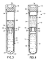
- FIG. 3 is a cross-sectional view of the assembly of FIG. 1 taken along line 2 — 2 thereof, showing the assembly at an intermediate stage of a centrifugation process.
- FIG. 4 is a cross-sectional view of the assembly of FIG. 1 taken along line 2 — 2 thereof, showing the assembly after completion of centrifugation.
- FIG. 5 is a perspective view of the flexible inner container and the filter assembly of the assembly.
- FIG. 6 is a cross-sectional view of the container and filter assembly of FIG. 5 taken along line 6 — 6 thereof.
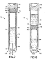
- FIG. 7 is a cross-sectional view of the container and filter assembly of FIG. 5 taken along 6 — 6 thereof, but showing an alternate container assembly.
- FIG. 8 is a cross-sectional view of the container and filter assembly of FIG. 5 taken along 6 — 6 thereof, but showing an alternate container assembly.
- assembly 10 includes an outer container 12 , an inner container 14 , a closure 16 and a filter assembly 18 .
- Outer container 12 is a rigid clear plastic or glass tube having an open top 20 , a closed bottom 22 and a cylindrical sidewall 24 extending between top 20 and bottom 22 .
- Cylindrical sidewall 24 defines an inside diameter “a” as shown in FIG. 1 .
- Inner container 14 is formed from a flexible and collapsible clear plastic material that is substantially impervious to fluid.
- Inner container 14 has an open top end 26 , a closed bottom end 28 and a flexible collapsible sidewall 30 extending therebetween.
- Closure 16 is formed from an elastomeric material and includes an outer skirt 32 dimensioned for sealed telescoped engagement over portions of cylindrical sidewall 24 of outer container 12 adjacent open top 20 thereof. Additionally, closure 16 includes a plug portion 34 dimensioned for sealed engagement within open top 20 of outer container 12 .
- the center region 36 of closure 16 is recessed and defines a resealable septum through which a needle cannula 38 can be inserted. Upon removal of needle cannula 38 , septum portion 36 will reseal itself.
- Filter assembly 18 includes a filter 40 and a filter support 42 .
- Filter 40 is formed from a material that will permit the less dense phase liquid to pass therethrough, while substantially preventing the more dense phase from passing therethrough. Filters with these performance specifications are commercially available and are marketed, for example, by Becton Dickinson as an Auto ISO-filter.
- filter 40 is a substantially thick-walled tubular shape and includes an inner circumferential surface 44 defining an inside diameter b and an outer circumferential surface 46 defining an outside diameter c. Filter 40 further includes a top end 48 and an opposed bottom end 50 .
- Filter support 42 is unitarily molded from a thermoplastic material and includes an outer cylindrical sidewall 52 having an inside diameter which is substantially equal to outside diameter c defined by outer circumferential surface 46 of filter 40 . Additionally, outer cylindrical sidewall 52 defines an outside diameter which is slightly less than inside diameter “a” defined by cylindrical sidewall 24 of outer container 12 . Relative dimensions of the outer cylindrical sidewall 52 of filter support 42 and cylindrical sidewall 24 of outer container 12 enable filter assembly 18 to move slidably within outer container 12 .
- Filter support 42 further includes a generally circular top wall 54 extending substantially continuously across an end of cylindrical sidewall 52 of filter support 42 .
- Top wall 54 is characterized by a pair of slit valves 56 extending arcuately at a location on top wall 54 that registers with top end 48 of filter 40 . Slit valves 56 remain substantially closed in an unbiased condition of top wall 54 . However, in response to fluid forces exerted on top wall 54 , the thermoplastic material of top wall 54 adjacent slit valves 56 will deform sufficiently to permit fluid flow therethrough.
- Top wall 54 is further characterized by a short inner cylindrical wall 58 extending downwardly therefrom and concentrically within outer cylindrical wall 52 . Inner cylindrical wall 58 defines an outside diameter approximately equal to inside diameter b of inner circumferential surface 44 of filter 40 . With this construction, filter 40 is effectively trapped between outer cylindrical wall 52 and inner cylindrical wall 58 .
- Filter support 42 further includes an annular bottom lip 60 extending inwardly from the end of outer cylindrical wall 52 opposite circular top wall 54 .
- Lip 60 functions to retain filter 40 between lip 60 and top wall 54 .
- Lip 60 may initially define a cylindrical extension of outer circumferential wall 52 , and subsequently may be formed inwardly as explained herein.
- Filter assembly 18 is assembled by slidably inserting tubular filter 40 into the end of filter support 42 opposite top wall 54 . Portions of inner container 14 adjacent open top end 26 are positioned adjacent portions of bottom end 50 of filter 40 adjacent outer circumferential surface 46 of filter 40 . The end of outer cylindrical wall 52 of filter support 42 opposite top wall 54 thereof then is deformed inwardly to define lip 60 . As a result, filter 40 is securely retained in filter support 42 and inner container 14 is securely engaged with filter assembly 18 .
- Assembly proceeds by sliding inner container 14 and filter assembly 18 into open top 20 of outer container 12 .
- Container assembly 10 then is enclosed by sealingly mounting closure 16 onto open top 20 of outer container 12 .
- a liquid sample is delivered into inner container 14 by needle 38 that penetrates through resealable septum portion 36 of stopper 16 and through portions of top wall 54 of filter support 42 .
- the liquid sample is blood.
- the sample of blood then is deposited into the inner container 14 , as shown in FIG. 2, and is isolated from the space between inner container 14 and outer container 12 .
- septum portion 36 of closure 16 reseals itself.
- Assembly 10 next is placed in a centrifuge such that top end 20 of outer container 12 is closer than the bottom end 22 to the axis of rotation of the centrifuge.
- the centrifuge than is operated to create centrifugal loading on blood sample 62 .
- the centrifugal loading urges the filter assembly in the direction indicated by arrow “A” toward bottom end 22 of outer container 12 and simultaneously generates a separation of the respective phases of the blood sample 62 in accordance with their densities. More specifically, red blood cells of blood sample 62 move away from the rotational axis of the centrifuge and toward closed bottom end 28 of inner container 14 .
- Assembly 70 includes a substantially rigid clear plastic or glass outer container 72 , a flexible collapsible inner container 74 , a closure 76 and a filter assembly 78 .
- Outer container 72 concludes an open top end 80 , an open bottom end 82 and a rigid cylindrical sidewall 84 extending therebetween.
- Sidewall 84 may define an inside diameter substantially the same as the inside diameter of the sidewall 24 of the first embodiment.
- Inner container 74 includes an open top end 86 , an open bottom end 88 and a flexible sidewall extending therebetween.
- Closure 76 is substantially identical to closure 16 described and illustrated above. Additionally, filter assembly 78 is structurally and functionally very similar to filter assembly 18 described and illustrated above. More particularly, filter assembly 78 includes a filter 90 and a filter support 92 .
- Filter 90 is a substantially solid cylindrical plug, as compared to the tubular filter of the previous embodiment.
- Filter support 92 includes a cylindrical outer sidewall 94 that surrounds filter 90 and a circular top wall 96 that extends across the continuous circular top end of filter 90 .
- Top wall 96 does not include a downwardly depending short cylindrical inner wall comparable to the cylindrical inner wall of the first embodiment. Thus, the circular top end of filter 90 can abut circular top wall 96 of filter support 92 .
- Top wall 96 includes at least one slit valve 98 that is comparable to the slit valves 56 described and illustrated with respect to the first embodiment. However, in view of the continuous solid cylindrical configuration of filter 90 , slit valves 98 may be disposed at any convenient locations on top wall 96 of filter support 92 . Open top end 86 of inner container 74 is securely engaged with filter 90 and filter support 92 substantially as described above.
- Assembly 70 further includes a bottom closure 100 that is securely engaged within the open bottom end 82 of outer container 72 and the open bottom end 82 of the inner container 74 . More particularly, bottom closure 100 is dimensioned to sealingly hold inner and outer container 74 and 72 respectively with one another at their open bottom ends. Bottom closure 100 includes a resealable septum 102 which is structurally and functionally similar to the resealable septum 36 of the top closure 16 described and illustrated above.
- Assembly 70 is used by initially depositing a sample of blood into inner container 72 by passing a needle cannula 38 through septum 102 of bottom closure 100 and placing the blood sample in inner container 74 .
- the assembly then is centrifuged substantially as described above.
- the centrifugation will cause filter assembly 78 to slidably move within outer container 72 and away from top closure 76 .
- the centrifugation will cause red blood cells of the collected blood sample to move toward bottom closure 100 , while serum will be urged toward top closure 76 .
- These centrifugal loads will cause serum to pass through filter 90 and the fluid pressure of the serum will open slit valves 98 such that the serum of the blood sample will move into the space between inner and outer containers 74 and 72 respectively.
- the centrifuge is stopped.
- the removal of the centrifugal load causes slit valves 98 to close, thereby maintaining separation between the serum and the red blood cells.
- Top closure 76 then is removed to access and remove the serum.
- the red blood cells within the inner container then may be accessed for subsequent analysis.
Abstract
A device and method for separating heavier and lighter fractions of a fluid sample. The device includes a flexible collapsible inner container disposed within a substantially rigid outer container. A closure seals the open top end of the outer container. A filter assembly is sealingly mounted to the open top end of the inner container. The filter assembly includes a filter that permits lighter fractions to pass therethrough, while substantially blocking the heavier fractions. The filter assembly further includes a filter support having a slit valve registered with the filter. The slit valve opens in response to fluid pressure created by the lighter fractions for permitting the lighter fractions to flow therethrough. A fluid sample is delivered to the inner container and the device is subjected to centrifugation whereby the centrifugal load causes the filter assembly to move toward the bottom end of the outer container and thereby enable the lighter fraction of the fluid sample to flow through the slit valve and into the space between the inner and outer containers. The slit valve closes upon termination of the centrifugal load such that separation between the heavier and lighter fractions of the fluid sample are maintained.
Description
This application claims the benefit of U.S. provisional application Ser. No. 60/168,819 filed Dec. 3, 1999, the disclosure of which is hereby incorporated by reference.
1. Field of the Invention
This invention relates to a device and method for separating heavier and lighter fractions of a fluid sample. More particularly, this invention relates to a device and method for collecting and transporting fluid samples whereby the device and fluid sample are subjected to centrifugation in order to cause separation of the heavier fraction from the lighter fraction of the fluid sample.
2. Description of Related Art
Diagnostic tests may require separation of a patient's whole blood sample into components, such as serum or plasma, the lighter phase component, and red blood cells, the heavier phase component. Samples of whole blood are typically collected by venipuncture through a cannula or needle attached to a syringe or an evacuated collection tube. Separation of the blood into serum or plasma and red blood cells is then accomplished by rotation of the syringe or tube in a centrifuge. Such arrangements use a barrier for moving into an area adjacent the two phases of the sample being separated to maintain the components separated for subsequent examination of the individual components.
A variety of devices have been used in collection devices to divide the area between the heavier and lighter phases of a fluid sample.
The most widely used device includes thixotropic gel materials such as polyester gels in a tube. The present polyester gel serum separation tubes require special manufacturing equipment to prepare the gel and to fill the tubes. Moreover, the shelf-life of the product is limited in that overtime globules may be released from the gel mass. These globules have a specific gravity that is less than the separated serum and may float in the serum and may clog the measuring instruments, such as the instrument probes used during the clinical examination of the sample collected in the tube. Such clogging can lead to considerable downtime for the instrument to remove the clog.
No commercially available gel is completely chemically inert to all analytes. If certain drugs are present in the blood sample when it is taken, there can be an adverse chemical reaction with the gel interface.
Therefore, a need exists for a separator device that (I) is easily used to separate a blood sample; (ii) is independent of temperature during storage and shipping; (iii) is stable to radiation sterilization; (iv) employs the benefits of a thixotropic gel barrier yet avoids the many disadvantages of placing a gel in contact with the separated blood components; (v) minimizes cross contamination of the heavier and lighter phases of the sample during centrifugation; (vi) minimizes adhesion of the lower and higher density materials against the separator device; (vii) is able to move into position to form a barrier in less time than conventional methods and devices; (viii) is able to provide a clearer specimen with less cell contamination methods and devices; and (ix) can be used with standard sampling equipment.
The present invention is a method and assembly for separating a fluid sample into a higher specific gravity phase and a lower specific gravity phase. Desirably, the assembly of the present invention includes a rigid outer container, a flexible inner container and a filter assembly for providing communication between the inner and outer containers.
The outer container may be a tube having opposed longitudinal ends and a substantially cylindrical sidewall extending therebetween. Both ends of the tube are substantially closed or closeable. For example, one end of the tube may have a permanent closure extending unitarily from the cylindrical sidewall of the tube. The opposed end of the tube may be substantially open, but may receive a needle pierceable resealable closure. Alternatively, both ends of the tube may be open, and both open ends of the tube may be sealed by elastomeric closures. At least one of the closures of the tube may include a needle pierceable resealable septum.
The inner container may be a flexible collapsible tubular bag formed from a transparent plastic material. The inner container is disposed within the outer container, and in a non-collapsed state may extend substantially between the opposed ends of the outer container. However, the inner container, such as the tubular plastic bag, is selectively collapsible toward one end of the outer container.
The filter assembly comprises a filter that is operative to permit blood serum to pass therethrough. However, the filter will substantially prevent the more dense red blood cells from passing therethrough. The filter assembly further includes a filter support in which the filter is securely retained. The filter support may comprise a cylindrical sidewall having opposed longitudinal ends. An end wall may extend across one longitudinal end of the cylindrical sidewall of the filter support. The end wall includes at least one slit valve formed therein. The slit valve is disposed at a location on the end wall that will substantially register with the filter. For example, the filter may define a substantially thick-walled tube retained by the support of the filter assembly. In this embodiment, the slit valve may define arc sections disposed on portions of the end wall that will register with one end of the tubular filter. In other embodiments, the filter may effectively define a continuous cylindrical plug that is securely engaged within the filter support. In this embodiment, the slit valve can take other configurations, such as a short diametrically aligned slit in the circular end wall.
In all embodiments, the filter assembly is dimensioned to be slidably moveable within the outer container. Additionally, the filter assembly and the flexible inner container define a secure fluid tight connection therebetween. For example, a tubular plastic bag defining the flexible inner container may have portions adjacent the open end disposed between the filter and inner surface areas of the filter support.
In use, a fluid sample enters the assembly by needle. The needle penetrates through the resealable closure and is urged into communication with the interior of the flexible inner container. The sample is then directed into the flexible inner container. The assembly is then placed in a centrifuge such that the filter assembly is at a radially inner position relative to the fluid sample within the flexible inner container. The centrifuge then is operated to place a centrifugal load on the assembly. The centrifugal load causes the more dense phase liquid to move outwardly relative to the axis of rotation of the centrifuge, and simultaneously causes the less dense phase liquid to move into locations closer to the axis of rotation of the centrifuge. The centrifugal load also causes the filter assembly to move away from the axis of rotation of the centrifuge. As a result, the less dense phase liquid is urged into the filter. The centrifugal load also causes the less dense phase liquid to open the slit valve sufficiently for the serum to flow out of the flexible inner container and into the space between the inner and outer containers. The outflow of the less dense phase liquid from the inner container causes the walls of the flexible inner container to collapse gradually, thereby decreasing the volume of the inner container. Simultaneously, there is a corresponding increase in the volume between the inner and outer containers as the less dense phase liquid flows through the filter assembly. After sufficient centrifugation, substantially all of the less dense phase liquid will have passed through the filter assembly. However, the filter prevents a flow of the more dense phase liquid therethrough. As a result, the more dense phase liquid is retained within the inner container, while the less dense phase liquid is retained in the space between the inner and outer containers. Additionally, upon termination of the centrifugal load, the less dense phase liquid disposed in the space between the inner and outer containers will not be subjected to any forces that would cause the less dense phase liquid to migrate back across the filter assembly and into the inner container. As a result, the two phases of the fluid sample may be removed separately from their respective containers and analyzed in a laboratory.
The assembly of the present invention is advantageous over existing separation products that use gel. In particular the assembly of the present invention will not interfere with analytes as compared to gels that may interfere with analytes. Another attribute of the present invention is that the assembly of the present invention will not interfere with therapeutic drug monitoring analytes.
Another notable advantage of the present invention is that fluid specimens are not subjected to low density gel residuals that are at times available in products that use gel.
A further attribute of the present invention is that there is no interference with instrument probes.
Another attribute of the present invention is that samples for blood banking tests are more acceptable than when a gel separator is used.
Additionally, the assembly of the present invention does not require any additional steps or treatment by a medical practitioner, whereby a blood or fluid sample is drawn in the standard fashion, using standard sampling equipment.
FIG. 1 is perspective view of the assembly of the present invention.
FIG. 2 is a cross-sectional view of the assembly of FIG. 1 taken along line 2—2 thereof and showing a needle depositing a sample of fluid into the assembly.
FIG. 3 is a cross-sectional view of the assembly of FIG. 1 taken along line 2—2 thereof, showing the assembly at an intermediate stage of a centrifugation process.
FIG. 4 is a cross-sectional view of the assembly of FIG. 1 taken along line 2—2 thereof, showing the assembly after completion of centrifugation.
FIG. 5 is a perspective view of the flexible inner container and the filter assembly of the assembly.
FIG. 6 is a cross-sectional view of the container and filter assembly of FIG. 5 taken along line 6—6 thereof.
FIG. 7 is a cross-sectional view of the container and filter assembly of FIG. 5 taken along 6—6 thereof, but showing an alternate container assembly.
FIG. 8 is a cross-sectional view of the container and filter assembly of FIG. 5 taken along 6—6 thereof, but showing an alternate container assembly.
The present invention is illustrated in FIGS. 1-4 wherein assembly 10 includes an outer container 12, an inner container 14, a closure 16 and a filter assembly 18.
As shown in FIG. 6, filter 40 is a substantially thick-walled tubular shape and includes an inner circumferential surface 44 defining an inside diameter b and an outer circumferential surface 46 defining an outside diameter c. Filter 40 further includes a top end 48 and an opposed bottom end 50.
Assembly proceeds by sliding inner container 14 and filter assembly 18 into open top 20 of outer container 12. Container assembly 10 then is enclosed by sealingly mounting closure 16 onto open top 20 of outer container 12.
As shown in FIG. 2, a liquid sample is delivered into inner container 14 by needle 38 that penetrates through resealable septum portion 36 of stopper 16 and through portions of top wall 54 of filter support 42. For purposes of illustration only, the liquid sample is blood. The sample of blood then is deposited into the inner container 14, as shown in FIG. 2, and is isolated from the space between inner container 14 and outer container 12. Upon removal of needle 38, septum portion 36 of closure 16 reseals itself.
An alternate assembly 70 in accordance with the present invention is shown in FIGS. 7 and 8. Assembly 70 includes a substantially rigid clear plastic or glass outer container 72, a flexible collapsible inner container 74, a closure 76 and a filter assembly 78.
Claims (15)
1. An assembly comprising:
an outer container having a bottom end, an open top end and a substantially rigid sidewall enclosure extending therebetween;
an inner container disposed within said outer container, said inner container having a bottom end in proximity to said bottom end of said outer container, an open top end and
a flexible collapsible sidewall enclosure extending therebetween;
a closure sealingly engaged with said open top end of said outer container for defining a sealed space between said inner and outer containers; and
a filter assembly movably disposed within said outer container and sealingly engaged with said open top of said inner container, said filter assembly comprising a filter that permits less dense phase of a liquid sample to flow therethrough and prevents more dense phase of the liquid sample from flowing therethrough.
2. The assembly of claim 1 , wherein the filter assembly further includes a filter support surrounding portions of said filter externally of said inner container, said filter support including at least one valve that is openable in response to fluid pressure thereon for permitting a flow of said less dense phase liquid through said filter assembly and into a space between said inner and outer containers.
3. The assembly of claim 2 , wherein the valve is a slit valve.
4. The assembly of claim 3 , wherein said filter is substantially tubular and has an inner circumferential surface, an outer circumferential surface, a bottom end and a top end, said bottom end of said filter and said inner circumferential surface thereof being in communication with interior portions of said inner container, said filter support including a cylindrical outer wall surrounding and engaging said outer circumferential surface of said filter, said filter support further having a top wall extending across one end of said cylindrical outer wall of said filter support, said at least one slit valve being substantially registered with said top end of said filter.
5. The assembly of claim 4 , wherein said at least one slit valve comprises a plurality of arcuate slit valves.
6. The assembly of claim 4 , wherein said filter support further comprises an inner cylindrical wall depending from said top wall of said filter support and engaging a portion of said inner circumferential surface of said filter.
7. The assembly of claim 4 , wherein portions of said inner container adjacent said open top thereof are sealingly engaged between said filter and said filter support.
8. The assembly of claim 7 , wherein said filter support further comprises an annular bottom wall extending inwardly from portions of said cylindrical outer wall of said filter support remote from said top wall, said bottom wall of said filter support engaging a portion of said bottom end of said filter for retaining said filter in said filter support.
9. The assembly of claim 8 , wherein portions of said inner container adjacent said open top thereof are sealingly engaged between said bottom end of said filter and said bottom wall of said filter support.
10. The assembly of claim 4 , wherein said outer container is unitarily formed and has a closed bottom, and wherein said inner container is unitarily formed and has a closed bottom.
11. The assembly of claim 4 , wherein said closure and said top wall of said filter support each include a central portion that is pierceable by a needle for depositing a sample of blood in said inner container, said closure being formed from a resealable elastomeric material.
12. The assembly of claim 3 , wherein said filter comprises substantially circular top and bottom ends and a cylindrical outer surface extending therebetween, said filter being substantially continuous between said top and bottom ends and inwardly of said outer circumferential surface, and wherein said filter support comprises a cylindrical outer wall surrounding and engaging said outer cylindrical surface of said filter and a circular top wall substantially abutting said circular top surface of said filter, said at least one slit valve being formed in said top wall of said filter support.
13. The assembly of claim 12 , wherein said filter support further comprises an annular bottom wall extending inwardly from portions of said cylindrical outer wall of said filter support remote from said top wall, said bottom wall of said filter support engaging portions of said bottom surface of said filter adjacent said outer cylindrical surface thereof.
14. The assembly of claim 12 , wherein portions of said inner container adjacent said open top thereof are sealingly engaged between said filter support and said filter.
15. The assembly of claim 12 , wherein said inner and outer containers each have open bottom ends, a needle pierceable closure being sealingly engaged with portions of said inner and outer containers adjacent said open bottom ends thereof, said bottom closure including a resealable septum for permitting passage of a needle cannula therethrough for depositing a sample of blood within said inner container.
Priority Applications (1)
| Application Number | Priority Date | Filing Date | Title |
|---|---|---|---|
| US09/727,162 US6471069B2 (en) | 1999-12-03 | 2000-11-30 | Device for separating components of a fluid sample |
Applications Claiming Priority (2)
| Application Number | Priority Date | Filing Date | Title |
|---|---|---|---|
| US16881999P | 1999-12-03 | 1999-12-03 | |
| US09/727,162 US6471069B2 (en) | 1999-12-03 | 2000-11-30 | Device for separating components of a fluid sample |
Publications (2)
| Publication Number | Publication Date |
|---|---|
| US20020064484A1 US20020064484A1 (en) | 2002-05-30 |
| US6471069B2 true US6471069B2 (en) | 2002-10-29 |
Family
ID=22613063
Family Applications (1)
| Application Number | Title | Priority Date | Filing Date |
|---|---|---|---|
| US09/727,162 Expired - Lifetime US6471069B2 (en) | 1999-12-03 | 2000-11-30 | Device for separating components of a fluid sample |
Country Status (4)
| Country | Link |
|---|---|
| US (1) | US6471069B2 (en) |
| EP (1) | EP1106250B1 (en) |
| JP (1) | JP4429521B2 (en) |
| DE (1) | DE60019240T2 (en) |
Cited By (53)
| Publication number | Priority date | Publication date | Assignee | Title |
|---|---|---|---|---|
| US20020004637A1 (en) * | 2000-07-06 | 2002-01-10 | Masayasu Sentoh | Sample suction apparatus |
| US20020131904A1 (en) * | 1998-12-05 | 2002-09-19 | Becton Dickinson And Company | Device and method for separating components of a fluid sample |
| US20040161788A1 (en) * | 2003-02-05 | 2004-08-19 | Shuqi Chen | Sample processing |
| US20050124073A1 (en) * | 2003-12-09 | 2005-06-09 | Entire Interest | Fat collection and preparation system and method |
| US20070003449A1 (en) * | 2005-06-10 | 2007-01-04 | Mehdi Hatamian | Valve for facilitating and maintaining fluid separation |
| WO2005055814A3 (en) * | 2003-12-09 | 2007-08-02 | Lipose Corp | Fat collection and preparation system and method |
| US20080003564A1 (en) * | 2006-02-14 | 2008-01-03 | Iquum, Inc. | Sample processing |
| US20080017577A1 (en) * | 2006-07-21 | 2008-01-24 | Becton, Dickinson And Company | Membrane-based Double-layer Tube for Sample Collections |
| US20080138251A1 (en) * | 2006-12-08 | 2008-06-12 | Bayer Healthcare Llc | Sample preparation device |
| US20080164223A1 (en) * | 2007-01-05 | 2008-07-10 | Wilson Kelce S | Floating filter holder |
| WO2009136694A2 (en) * | 2008-05-09 | 2009-11-12 | Eum Young Rok | Teflon container for sample decomposition using gas condensation by air cooling |
| US20100093551A1 (en) * | 2008-10-09 | 2010-04-15 | Decision Biomarkers, Inc. | Liquid Transfer and Filter System |
| US20100140182A1 (en) * | 2008-12-04 | 2010-06-10 | Chapman John R | Apparatus and method for separating and isolating components of a biological fluid |
| US20100248215A1 (en) * | 2007-11-20 | 2010-09-30 | Halverson Kurt J | Sample preparation container and method |
| US20100248216A1 (en) * | 2007-11-20 | 2010-09-30 | 3M Innovative Properties Company | Sample preparation container and method |
| US20100255484A1 (en) * | 2007-11-20 | 2010-10-07 | Halverson Kurt J | Sample preparation container and method |
| US20100285520A1 (en) * | 2007-11-20 | 2010-11-11 | Halverson Kurt J | Sample preparation for environmental sampling |
| US8313954B2 (en) | 2009-04-03 | 2012-11-20 | Biomet Biologics, Llc | All-in-one means of separating blood components |
| US8328024B2 (en) | 2007-04-12 | 2012-12-11 | Hanuman, Llc | Buoy suspension fractionation system |
| US8337711B2 (en) | 2008-02-29 | 2012-12-25 | Biomet Biologics, Llc | System and process for separating a material |
| US8394342B2 (en) | 2008-07-21 | 2013-03-12 | Becton, Dickinson And Company | Density phase separation device |
| US8465471B2 (en) | 2009-08-05 | 2013-06-18 | Rocin Laboratories, Inc. | Endoscopically-guided electro-cauterizing power-assisted fat aspiration system for aspirating visceral fat tissue within the abdomen of a patient |
| US8567609B2 (en) | 2006-05-25 | 2013-10-29 | Biomet Biologics, Llc | Apparatus and method for separating and concentrating fluids containing multiple components |
| US8591391B2 (en) | 2010-04-12 | 2013-11-26 | Biomet Biologics, Llc | Method and apparatus for separating a material |
| US8596470B2 (en) | 2007-04-12 | 2013-12-03 | Hanuman, Llc | Buoy fractionation system |
| US8603346B2 (en) | 2002-05-24 | 2013-12-10 | Biomet Biologics, Llc | Apparatus and method for separating and concentrating fluids containing multiple components |
| WO2014025490A1 (en) | 2012-08-10 | 2014-02-13 | Montagu Jean I | Filtering blood |
| US8747781B2 (en) | 2008-07-21 | 2014-06-10 | Becton, Dickinson And Company | Density phase separation device |
| US8783470B2 (en) | 2009-03-06 | 2014-07-22 | Biomet Biologics, Llc | Method and apparatus for producing autologous thrombin |
| US8794452B2 (en) | 2009-05-15 | 2014-08-05 | Becton, Dickinson And Company | Density phase separation device |
| US8808551B2 (en) | 2002-05-24 | 2014-08-19 | Biomet Biologics, Llc | Apparatus and method for separating and concentrating fluids containing multiple components |
| US8950586B2 (en) | 2002-05-03 | 2015-02-10 | Hanuman Llc | Methods and apparatus for isolating platelets from blood |
| US8991239B2 (en) | 2006-05-22 | 2015-03-31 | 3M Innovative Properties Company | System and method for preparing samples |
| US9011800B2 (en) | 2009-07-16 | 2015-04-21 | Biomet Biologics, Llc | Method and apparatus for separating biological materials |
| US9333445B2 (en) | 2008-07-21 | 2016-05-10 | Becton, Dickinson And Company | Density phase separation device |
| US9556243B2 (en) | 2013-03-15 | 2017-01-31 | Biomet Biologies, LLC | Methods for making cytokine compositions from tissues using non-centrifugal methods |
| US9642956B2 (en) | 2012-08-27 | 2017-05-09 | Biomet Biologics, Llc | Apparatus and method for separating and concentrating fluids containing multiple components |
| US9682373B2 (en) | 1999-12-03 | 2017-06-20 | Becton, Dickinson And Company | Device for separating components of a fluid sample |
| US9694359B2 (en) | 2014-11-13 | 2017-07-04 | Becton, Dickinson And Company | Mechanical separator for a biological fluid |
| US9701728B2 (en) | 2008-02-27 | 2017-07-11 | Biomet Biologics, Llc | Methods and compositions for delivering interleukin-1 receptor antagonist |
| US9744274B2 (en) | 2009-08-05 | 2017-08-29 | Rocin Laboratories, Inc. | Tissue sampling, processing and collection device and method of using same |
| US9897589B2 (en) | 2002-05-24 | 2018-02-20 | Biomet Biologics, Llc | Apparatus and method for separating and concentrating fluids containing multiple components |
| US9895418B2 (en) | 2013-03-15 | 2018-02-20 | Biomet Biologics, Llc | Treatment of peripheral vascular disease using protein solutions |
| US9925314B2 (en) | 2009-08-05 | 2018-03-27 | Rocin Laboratories, Inc. | Method of performing intra-abdominal tissue aspiration to ameliorate the metabolic syndrome, or abdominal obesity |
| US9950035B2 (en) | 2013-03-15 | 2018-04-24 | Biomet Biologics, Llc | Methods and non-immunogenic compositions for treating inflammatory disorders |
| US10143725B2 (en) | 2013-03-15 | 2018-12-04 | Biomet Biologics, Llc | Treatment of pain using protein solutions |
| US10195320B2 (en) * | 2012-04-12 | 2019-02-05 | Sisu Global Health, Inc. | Blood filtering component, apparatus, and method |
| US10576130B2 (en) | 2013-03-15 | 2020-03-03 | Biomet Manufacturing, Llc | Treatment of collagen defects using protein solutions |
| USD890359S1 (en) * | 2016-08-19 | 2020-07-14 | Dna Genotek Inc. | False bottom tube with cap and plug |
| US11002646B2 (en) | 2011-06-19 | 2021-05-11 | DNA Genotek, Inc. | Devices, solutions and methods for sample collection |
| US11572581B2 (en) | 2002-06-07 | 2023-02-07 | DNA Genotek, Inc. | Compositions and methods for obtaining nucleic acids from sputum |
| US11697114B2 (en) * | 2015-12-11 | 2023-07-11 | Babson Diagnostics, Inc. | Centrifugation method separating serum or plasma from whole blood using a specimen container having a cap to retain blood cells |
| US11833279B2 (en) | 2021-06-11 | 2023-12-05 | Astaria Global, LLC | System and method for isolating alpha 2M molecules |
Families Citing this family (24)
| Publication number | Priority date | Publication date | Assignee | Title |
|---|---|---|---|---|
| US6780617B2 (en) | 2000-12-29 | 2004-08-24 | Chen & Chen, Llc | Sample processing device and method |
| AU4957699A (en) | 1998-06-24 | 2000-01-10 | Chen & Chen, Llc | Fluid sample testing system |
| US7799521B2 (en) | 1998-06-24 | 2010-09-21 | Chen & Chen, Llc | Thermal cycling |
| AT500247B1 (en) | 2001-03-30 | 2007-06-15 | Greiner Bio One Gmbh | RECEIVING DEVICE, ESPECIALLY FOR BODY FLUIDS, WITH A SEPARATION DEVICE AND SEPARATING DEVICE THEREFOR |
| EP1427531B1 (en) * | 2001-09-11 | 2016-10-19 | Iquum, Inc. | Sample vessels |
| US7700276B2 (en) * | 2003-07-10 | 2010-04-20 | Universite Libre De Bruxelles | Device, kit and method for pulsing biological samples with an agent and stabilising the sample so pulsed |
| US7947450B2 (en) | 2003-07-10 | 2011-05-24 | Universite Libre De Bruxelles | Device, kit and method for pulsing biological samples with an agent and stabilising the sample so pulsed |
| US20050065454A1 (en) * | 2003-09-22 | 2005-03-24 | Becton, Dickinson And Company | Non-evacuated blood collection tube |
| AT500459B1 (en) | 2004-01-23 | 2010-08-15 | Greiner Bio One Gmbh | METHOD FOR ASSEMBLING A CAP WITH A RECEIVING CONTAINER |
| AT414322B (en) * | 2004-11-29 | 2007-03-15 | Greiner Bio One Gmbh | SEPARATING DEVICE, ESPECIALLY FOR BODY FLUIDS, AND RECORDING EQUIPMENT WITH SUCH A SEPARATING DEVICE |
| ES2938924T3 (en) * | 2008-03-05 | 2023-04-17 | Becton Dickinson Co | Capillary action collection device |
| KR101609226B1 (en) | 2008-12-04 | 2016-04-06 | 써모제너시스 코포레이션 | Apparatus and method for separating and isolating components of a biological fluid |
| WO2011116408A1 (en) * | 2010-03-25 | 2011-09-29 | Sdi Limited | Liquid container |
| WO2012003873A1 (en) * | 2010-07-08 | 2012-01-12 | Matthias Zumstein | Device and method for collecting platelet concentrate |
| KR101459109B1 (en) * | 2012-05-21 | 2014-11-12 | 한국과학기술원 | Container for multiple centrifugation and Particle Separation Method Using the Same |
| JP5714063B2 (en) * | 2013-07-16 | 2015-05-07 | サーモジェネシス コーポレーション | Apparatus and method for separating and isolating body fluid components |
| SG11201707461YA (en) * | 2015-03-17 | 2017-10-30 | Mbs Co Ltd | Sample collection and separation device |
| EP3293523B1 (en) | 2016-03-14 | 2020-10-07 | Kobe Bio Robotix Co. Ltd. | Sample container and automatic sample container processing system |
| CN106148176A (en) * | 2016-08-17 | 2016-11-23 | 桂林医学院 | A kind of cell cultivation centrifuge tube |
| CN106353137B (en) * | 2016-08-30 | 2023-10-31 | 徐州憬美新材料科技有限公司 | Liquid taking container assembly and liquid taking method |
| US11602750B2 (en) | 2017-05-30 | 2023-03-14 | Roche Molecular Systems, Inc. | Customizable sample processing device |
| US10906035B2 (en) * | 2017-05-30 | 2021-02-02 | Roche Molecular Systems, Inc. | Modified sample processing device |
| WO2020146575A1 (en) * | 2019-01-09 | 2020-07-16 | Stem Cell Partners, Llc | Collapsible centrifugation vial system and method |
| TW202208062A (en) * | 2020-08-20 | 2022-03-01 | 財桂生物股份有限公司 | Pipette cover and assembling device thereof that comprises a closure part for sealing a pipette container and a fitting notch for detachable connection with a drive device |
Citations (21)
| Publication number | Priority date | Publication date | Assignee | Title |
|---|---|---|---|---|
| US3849072A (en) | 1972-04-25 | 1974-11-19 | Becton Dickinson Co | Plasma separator |
| US4083788A (en) | 1975-11-19 | 1978-04-11 | Ferrara Louis T | Blood serum-isolation device |
| US4088582A (en) | 1976-01-16 | 1978-05-09 | Sherwood Medical Industries Inc. | Blood phase separation means |
| US4131549A (en) | 1977-05-16 | 1978-12-26 | Ferrara Louis T | Serum separation device |
| US4154690A (en) | 1977-03-16 | 1979-05-15 | Uwe Ballies | Device for use in the centrifugal separation of components of a liquid |
| EP0017127A2 (en) | 1979-03-23 | 1980-10-15 | Terumo Corporation | A method for separating blood and a barrier device therefor |
| US4257886A (en) | 1979-01-18 | 1981-03-24 | Becton, Dickinson And Company | Apparatus for the separation of blood components |
| US4364832A (en) | 1981-01-21 | 1982-12-21 | Ballies Uwe W | Separating member in a separating tube for centrifugal separation |
| US4417981A (en) | 1981-05-04 | 1983-11-29 | Becton, Dickinson And Company | Blood phase separator device |
| US4443345A (en) | 1982-06-28 | 1984-04-17 | Wells John R | Serum preparator |
| US4818386A (en) | 1987-10-08 | 1989-04-04 | Becton, Dickinson And Company | Device for separating the components of a liquid sample having higher and lower specific gravities |
| US4853137A (en) | 1985-08-27 | 1989-08-01 | Ersson Nils Olof | Method and device for separating serum/plasma from blood |
| US4877520A (en) | 1987-10-08 | 1989-10-31 | Becton, Dickinson And Company | Device for separating the components of a liquid sample having higher and lower specific gravities |
| US5269927A (en) | 1991-05-29 | 1993-12-14 | Sherwood Medical Company | Separation device for use in blood collection tubes |
| JPH06222055A (en) | 1993-01-22 | 1994-08-12 | Niigata Kako Kk | Component separating member for liquid sample |
| EP0627261A2 (en) | 1993-06-02 | 1994-12-07 | E.I. Du Pont De Nemours And Company | Phase-separation tube |
| EP0638804A1 (en) | 1993-08-13 | 1995-02-15 | Niigata Chemicals And Plastics Co. Ltd | Serum separating device and apparatus for serum separation |
| US5455009A (en) | 1993-09-14 | 1995-10-03 | Becton, Dickinson And Company | Blood collection assembly including clot-accelerating plastic insert |
| US5575778A (en) | 1994-09-21 | 1996-11-19 | B. Braun Melsungen Ag | Blood-taking device |
| US5632905A (en) | 1995-08-07 | 1997-05-27 | Haynes; John L. | Method and apparatus for separating formed and unformed components |
| US6063297A (en) | 1994-12-07 | 2000-05-16 | Plasmaseal Llc | Method and apparatus for making concentrated plasma and/or tissue sealant |
Family Cites Families (5)
| Publication number | Priority date | Publication date | Assignee | Title |
|---|---|---|---|---|
| US3954614A (en) * | 1972-07-31 | 1976-05-04 | Glasrock Products, Inc. | Serum skimmer and filter separation unit |
| US3891553A (en) * | 1974-02-27 | 1975-06-24 | Becton Dickinson Co | Serum and plasma separator {13 {0 constrictionless type |
| US3894950A (en) * | 1974-02-27 | 1975-07-15 | Becton Dickinson Co | Serum separator improvement with stretchable filter diaphragm |
| US3972812A (en) * | 1975-05-08 | 1976-08-03 | Becton, Dickinson And Company | Blood serum separation filter disc |
| US4369117A (en) * | 1980-05-12 | 1983-01-18 | American Hospital Supply Corporation | Serum separating method and apparatus |
-
2000
- 2000-11-30 US US09/727,162 patent/US6471069B2/en not_active Expired - Lifetime
- 2000-12-01 DE DE60019240T patent/DE60019240T2/en not_active Expired - Lifetime
- 2000-12-01 EP EP00125384A patent/EP1106250B1/en not_active Expired - Lifetime
- 2000-12-04 JP JP2000369176A patent/JP4429521B2/en not_active Expired - Lifetime
Patent Citations (21)
| Publication number | Priority date | Publication date | Assignee | Title |
|---|---|---|---|---|
| US3849072A (en) | 1972-04-25 | 1974-11-19 | Becton Dickinson Co | Plasma separator |
| US4083788A (en) | 1975-11-19 | 1978-04-11 | Ferrara Louis T | Blood serum-isolation device |
| US4088582A (en) | 1976-01-16 | 1978-05-09 | Sherwood Medical Industries Inc. | Blood phase separation means |
| US4154690A (en) | 1977-03-16 | 1979-05-15 | Uwe Ballies | Device for use in the centrifugal separation of components of a liquid |
| US4131549A (en) | 1977-05-16 | 1978-12-26 | Ferrara Louis T | Serum separation device |
| US4257886A (en) | 1979-01-18 | 1981-03-24 | Becton, Dickinson And Company | Apparatus for the separation of blood components |
| EP0017127A2 (en) | 1979-03-23 | 1980-10-15 | Terumo Corporation | A method for separating blood and a barrier device therefor |
| US4364832A (en) | 1981-01-21 | 1982-12-21 | Ballies Uwe W | Separating member in a separating tube for centrifugal separation |
| US4417981A (en) | 1981-05-04 | 1983-11-29 | Becton, Dickinson And Company | Blood phase separator device |
| US4443345A (en) | 1982-06-28 | 1984-04-17 | Wells John R | Serum preparator |
| US4853137A (en) | 1985-08-27 | 1989-08-01 | Ersson Nils Olof | Method and device for separating serum/plasma from blood |
| US4818386A (en) | 1987-10-08 | 1989-04-04 | Becton, Dickinson And Company | Device for separating the components of a liquid sample having higher and lower specific gravities |
| US4877520A (en) | 1987-10-08 | 1989-10-31 | Becton, Dickinson And Company | Device for separating the components of a liquid sample having higher and lower specific gravities |
| US5269927A (en) | 1991-05-29 | 1993-12-14 | Sherwood Medical Company | Separation device for use in blood collection tubes |
| JPH06222055A (en) | 1993-01-22 | 1994-08-12 | Niigata Kako Kk | Component separating member for liquid sample |
| EP0627261A2 (en) | 1993-06-02 | 1994-12-07 | E.I. Du Pont De Nemours And Company | Phase-separation tube |
| EP0638804A1 (en) | 1993-08-13 | 1995-02-15 | Niigata Chemicals And Plastics Co. Ltd | Serum separating device and apparatus for serum separation |
| US5455009A (en) | 1993-09-14 | 1995-10-03 | Becton, Dickinson And Company | Blood collection assembly including clot-accelerating plastic insert |
| US5575778A (en) | 1994-09-21 | 1996-11-19 | B. Braun Melsungen Ag | Blood-taking device |
| US6063297A (en) | 1994-12-07 | 2000-05-16 | Plasmaseal Llc | Method and apparatus for making concentrated plasma and/or tissue sealant |
| US5632905A (en) | 1995-08-07 | 1997-05-27 | Haynes; John L. | Method and apparatus for separating formed and unformed components |
Cited By (141)
| Publication number | Priority date | Publication date | Assignee | Title |
|---|---|---|---|---|
| US7153477B2 (en) * | 1998-12-05 | 2006-12-26 | Becton Dickinson And Company | Device and method for separating components of a fluid sample |
| US20020131904A1 (en) * | 1998-12-05 | 2002-09-19 | Becton Dickinson And Company | Device and method for separating components of a fluid sample |
| US20100012598A1 (en) * | 1998-12-05 | 2010-01-21 | Becton, Dickinson And Company | Device and Method for Separating Components of a Fluid Sample |
| US7578975B2 (en) * | 1998-12-05 | 2009-08-25 | Becton, Dickinson And Company | Device and method for separating components of a fluid sample |
| US7972578B2 (en) | 1998-12-05 | 2011-07-05 | Becton, Dickinson And Company | Device and method for separating components of a fluid sample |
| US20060263266A1 (en) * | 1998-12-05 | 2006-11-23 | Becton, Dickinson And Company | Device and method for separating components of a fluid sample |
| US9682373B2 (en) | 1999-12-03 | 2017-06-20 | Becton, Dickinson And Company | Device for separating components of a fluid sample |
| US7867451B2 (en) | 2000-07-06 | 2011-01-11 | Sysmex Corporation | Sample suction apparatus |
| US20050042142A1 (en) * | 2000-07-06 | 2005-02-24 | Sysmex Corporation | Sample suction apparatus |
| US6833113B2 (en) * | 2000-07-06 | 2004-12-21 | Sysmex Corporation | Sample suction apparatus |
| US20020004637A1 (en) * | 2000-07-06 | 2002-01-10 | Masayasu Sentoh | Sample suction apparatus |
| US20080247909A1 (en) * | 2000-07-06 | 2008-10-09 | Masayasu Sentoh | Sample suction apparatus |
| US7381372B2 (en) | 2000-07-06 | 2008-06-03 | Sysmex Corporation | Sample suction apparatus |
| US8950586B2 (en) | 2002-05-03 | 2015-02-10 | Hanuman Llc | Methods and apparatus for isolating platelets from blood |
| US10393728B2 (en) | 2002-05-24 | 2019-08-27 | Biomet Biologics, Llc | Apparatus and method for separating and concentrating fluids containing multiple components |
| US9114334B2 (en) | 2002-05-24 | 2015-08-25 | Biomet Biologics, Llc | Apparatus and method for separating and concentrating fluids containing multiple components |
| US10183042B2 (en) | 2002-05-24 | 2019-01-22 | Biomet Manufacturing, Llc | Apparatus and method for separating and concentrating fluids containing multiple components |
| US8603346B2 (en) | 2002-05-24 | 2013-12-10 | Biomet Biologics, Llc | Apparatus and method for separating and concentrating fluids containing multiple components |
| US9897589B2 (en) | 2002-05-24 | 2018-02-20 | Biomet Biologics, Llc | Apparatus and method for separating and concentrating fluids containing multiple components |
| US8808551B2 (en) | 2002-05-24 | 2014-08-19 | Biomet Biologics, Llc | Apparatus and method for separating and concentrating fluids containing multiple components |
| US11572581B2 (en) | 2002-06-07 | 2023-02-07 | DNA Genotek, Inc. | Compositions and methods for obtaining nucleic acids from sputum |
| US7718421B2 (en) | 2003-02-05 | 2010-05-18 | Iquum, Inc. | Sample processing |
| US9708599B2 (en) | 2003-02-05 | 2017-07-18 | Roche Molecular Systems, Inc. | Sample processing methods |
| US10443050B2 (en) | 2003-02-05 | 2019-10-15 | Roche Molecular Systems, Inc. | Sample processing methods |
| US20040161788A1 (en) * | 2003-02-05 | 2004-08-19 | Shuqi Chen | Sample processing |
| US8936933B2 (en) | 2003-02-05 | 2015-01-20 | IQumm, Inc. | Sample processing methods |
| WO2005055814A3 (en) * | 2003-12-09 | 2007-08-02 | Lipose Corp | Fat collection and preparation system and method |
| AU2004296873B2 (en) * | 2003-12-09 | 2009-10-08 | Lipose Corporation | Fat collection and preparation system and method |
| US7488427B2 (en) | 2003-12-09 | 2009-02-10 | Lipose Corporation | Fat collection and preparation system and method |
| US20080057597A1 (en) * | 2003-12-09 | 2008-03-06 | Freund Robert M | Fat collection and preparation system and method |
| US20050124073A1 (en) * | 2003-12-09 | 2005-06-09 | Entire Interest | Fat collection and preparation system and method |
| US20070003449A1 (en) * | 2005-06-10 | 2007-01-04 | Mehdi Hatamian | Valve for facilitating and maintaining fluid separation |
| US20080003564A1 (en) * | 2006-02-14 | 2008-01-03 | Iquum, Inc. | Sample processing |
| US8991239B2 (en) | 2006-05-22 | 2015-03-31 | 3M Innovative Properties Company | System and method for preparing samples |
| US8567609B2 (en) | 2006-05-25 | 2013-10-29 | Biomet Biologics, Llc | Apparatus and method for separating and concentrating fluids containing multiple components |
| US20080017577A1 (en) * | 2006-07-21 | 2008-01-24 | Becton, Dickinson And Company | Membrane-based Double-layer Tube for Sample Collections |
| US7534397B2 (en) | 2006-12-08 | 2009-05-19 | Nicolae Dumitrescu | Sample preparation device |
| US20080138251A1 (en) * | 2006-12-08 | 2008-06-12 | Bayer Healthcare Llc | Sample preparation device |
| US7767087B2 (en) * | 2007-01-05 | 2010-08-03 | Wilson Kelce S | Floating filter holder |
| US7955501B2 (en) | 2007-01-05 | 2011-06-07 | Kelce Steven Wilson | Floating filter holder |
| US20080164223A1 (en) * | 2007-01-05 | 2008-07-10 | Wilson Kelce S | Floating filter holder |
| US9649579B2 (en) | 2007-04-12 | 2017-05-16 | Hanuman Llc | Buoy suspension fractionation system |
| US8596470B2 (en) | 2007-04-12 | 2013-12-03 | Hanuman, Llc | Buoy fractionation system |
| US8328024B2 (en) | 2007-04-12 | 2012-12-11 | Hanuman, Llc | Buoy suspension fractionation system |
| US9138664B2 (en) | 2007-04-12 | 2015-09-22 | Biomet Biologics, Llc | Buoy fractionation system |
| US8569072B2 (en) | 2007-11-20 | 2013-10-29 | 3M Innovative Properties Company | Sample preparation container and method |
| US20100285520A1 (en) * | 2007-11-20 | 2010-11-11 | Halverson Kurt J | Sample preparation for environmental sampling |
| US20100255484A1 (en) * | 2007-11-20 | 2010-10-07 | Halverson Kurt J | Sample preparation container and method |
| US20100248216A1 (en) * | 2007-11-20 | 2010-09-30 | 3M Innovative Properties Company | Sample preparation container and method |
| US20100248215A1 (en) * | 2007-11-20 | 2010-09-30 | Halverson Kurt J | Sample preparation container and method |
| US8647574B2 (en) | 2007-11-20 | 2014-02-11 | 3M Innovative Properties Company | Sample preparation container and method |
| US8685746B2 (en) | 2007-11-20 | 2014-04-01 | 3M Innovative Properties Company | Sample preparation container and method |
| US8563264B2 (en) | 2007-11-20 | 2013-10-22 | 3M Innovative Properties Company | Sample preparation for environmental sampling |
| US11725031B2 (en) | 2008-02-27 | 2023-08-15 | Biomet Manufacturing, Llc | Methods and compositions for delivering interleukin-1 receptor antagonist |
| US10400017B2 (en) | 2008-02-27 | 2019-09-03 | Biomet Biologics, Llc | Methods and compositions for delivering interleukin-1 receptor antagonist |
| US9701728B2 (en) | 2008-02-27 | 2017-07-11 | Biomet Biologics, Llc | Methods and compositions for delivering interleukin-1 receptor antagonist |
| US8801586B2 (en) * | 2008-02-29 | 2014-08-12 | Biomet Biologics, Llc | System and process for separating a material |
| US9719063B2 (en) | 2008-02-29 | 2017-08-01 | Biomet Biologics, Llc | System and process for separating a material |
| US8337711B2 (en) | 2008-02-29 | 2012-12-25 | Biomet Biologics, Llc | System and process for separating a material |
| GB2473757A (en) * | 2008-05-09 | 2011-03-23 | Young Rok Eum | Teflon container for sample decomposition using gas condensation by air cooling |
| US8513026B2 (en) | 2008-05-09 | 2013-08-20 | Young Rok Eum | Teflon container for sample decomposition using gas condensation by air cooling |
| WO2009136694A2 (en) * | 2008-05-09 | 2009-11-12 | Eum Young Rok | Teflon container for sample decomposition using gas condensation by air cooling |
| KR100933151B1 (en) | 2008-05-09 | 2009-12-21 | 엄영록 | Teflon Sampling Vessel Using Gas Condensation by Air Cooling |
| US20110033949A1 (en) * | 2008-05-09 | 2011-02-10 | Young Rok Eum | Teflon container for sample decomposition using gas condensation by air cooling |
| GB2473757B (en) * | 2008-05-09 | 2013-01-09 | Young Rok Eum | Teflon vessel for sample decomposition using gas condensation by air cooling |
| WO2009136694A3 (en) * | 2008-05-09 | 2009-12-30 | Eum Young Rok | Teflon container for sample decomposition using gas condensation by air cooling |
| CN102006937B (en) * | 2008-05-09 | 2013-09-25 | 严永禄 | Teflon container for sample decomposition using gas condensation by air cooling |
| CN102006937A (en) * | 2008-05-09 | 2011-04-06 | 严永禄 | Teflon container for sample decomposition using gas condensation by air cooling |
| US9333445B2 (en) | 2008-07-21 | 2016-05-10 | Becton, Dickinson And Company | Density phase separation device |
| US9714890B2 (en) | 2008-07-21 | 2017-07-25 | Becton, Dickinson And Company | Density phase separation device |
| US9452427B2 (en) | 2008-07-21 | 2016-09-27 | Becton, Dickinson And Company | Density phase separation device |
| US9700886B2 (en) | 2008-07-21 | 2017-07-11 | Becton, Dickinson And Company | Density phase separation device |
| US9339741B2 (en) | 2008-07-21 | 2016-05-17 | Becton, Dickinson And Company | Density phase separation device |
| US10350591B2 (en) | 2008-07-21 | 2019-07-16 | Becton, Dickinson And Company | Density phase separation device |
| US8747781B2 (en) | 2008-07-21 | 2014-06-10 | Becton, Dickinson And Company | Density phase separation device |
| US8394342B2 (en) | 2008-07-21 | 2013-03-12 | Becton, Dickinson And Company | Density phase separation device |
| US9933344B2 (en) | 2008-07-21 | 2018-04-03 | Becton, Dickinson And Company | Density phase separation device |
| US20100093551A1 (en) * | 2008-10-09 | 2010-04-15 | Decision Biomarkers, Inc. | Liquid Transfer and Filter System |
| US8511479B2 (en) * | 2008-12-04 | 2013-08-20 | Thermogenesis Corp. | Apparatus and method for separating and isolating components of a biological fluid |
| US20100140182A1 (en) * | 2008-12-04 | 2010-06-10 | Chapman John R | Apparatus and method for separating and isolating components of a biological fluid |
| US8506823B2 (en) * | 2008-12-04 | 2013-08-13 | Thermogenesis Corp. | Apparatus and method for separating and isolating components of a biological fluid |
| US9375661B2 (en) | 2008-12-04 | 2016-06-28 | Cesca Therapeutics, Inc. | Apparatus and method for separating and isolating components of a biological fluid |
| US8177072B2 (en) | 2008-12-04 | 2012-05-15 | Thermogenesis Corp. | Apparatus and method for separating and isolating components of a biological fluid |
| US8511480B2 (en) * | 2008-12-04 | 2013-08-20 | Thermogenesis Corp. | Apparatus and method for separating and isolating components of a biological fluid |
| US20120122649A1 (en) * | 2008-12-04 | 2012-05-17 | Chapman John R | Apparatus and method for separating and isolating components of a biological fluid |
| US20120193274A1 (en) * | 2008-12-04 | 2012-08-02 | Chapman John R | Apparatus and method for separating and isolating components of a biological fluid |
| US8783470B2 (en) | 2009-03-06 | 2014-07-22 | Biomet Biologics, Llc | Method and apparatus for producing autologous thrombin |
| US8992862B2 (en) | 2009-04-03 | 2015-03-31 | Biomet Biologics, Llc | All-in-one means of separating blood components |
| US8313954B2 (en) | 2009-04-03 | 2012-11-20 | Biomet Biologics, Llc | All-in-one means of separating blood components |
| US10413898B2 (en) | 2009-05-15 | 2019-09-17 | Becton, Dickinson And Company | Density phase separation device |
| US9802189B2 (en) | 2009-05-15 | 2017-10-31 | Becton, Dickinson And Company | Density phase separation device |
| US11786895B2 (en) | 2009-05-15 | 2023-10-17 | Becton, Dickinson And Company | Density phase separation device |
| US11351535B2 (en) | 2009-05-15 | 2022-06-07 | Becton, Dickinson And Company | Density phase separation device |
| US10807088B2 (en) | 2009-05-15 | 2020-10-20 | Becton, Dickinson And Company | Density phase separation device |
| US10456782B2 (en) | 2009-05-15 | 2019-10-29 | Becton, Dickinson And Company | Density phase separation device |
| US9731290B2 (en) | 2009-05-15 | 2017-08-15 | Becton, Dickinson And Company | Density phase separation device |
| US8794452B2 (en) | 2009-05-15 | 2014-08-05 | Becton, Dickinson And Company | Density phase separation device |
| US8998000B2 (en) | 2009-05-15 | 2015-04-07 | Becton, Dickinson And Company | Density phase separation device |
| US9919308B2 (en) | 2009-05-15 | 2018-03-20 | Becton, Dickinson And Company | Density phase separation device |
| US9919309B2 (en) | 2009-05-15 | 2018-03-20 | Becton, Dickinson And Company | Density phase separation device |
| US10376879B2 (en) | 2009-05-15 | 2019-08-13 | Becton, Dickinson And Company | Density phase separation device |
| US9079123B2 (en) | 2009-05-15 | 2015-07-14 | Becton, Dickinson And Company | Density phase separation device |
| US9364828B2 (en) | 2009-05-15 | 2016-06-14 | Becton, Dickinson And Company | Density phase separation device |
| US10343157B2 (en) | 2009-05-15 | 2019-07-09 | Becton, Dickinson And Company | Density phase separation device |
| US9919307B2 (en) | 2009-05-15 | 2018-03-20 | Becton, Dickinson And Company | Density phase separation device |
| US9011800B2 (en) | 2009-07-16 | 2015-04-21 | Biomet Biologics, Llc | Method and apparatus for separating biological materials |
| US9833279B2 (en) | 2009-08-05 | 2017-12-05 | Rocin Laboratories, Inc. | Twin-cannula tissue aspiration instrument system |
| US9821096B2 (en) | 2009-08-05 | 2017-11-21 | Rocin Laboratories, Inc. | Tissue sampling, processing and injection syringe device and methods of using the same |
| US9744274B2 (en) | 2009-08-05 | 2017-08-29 | Rocin Laboratories, Inc. | Tissue sampling, processing and collection device and method of using same |
| US9757184B2 (en) | 2009-08-05 | 2017-09-12 | Rocin Laboratories, Inc. | In-line fat tissue sampling, processing and collection device |
| US9925314B2 (en) | 2009-08-05 | 2018-03-27 | Rocin Laboratories, Inc. | Method of performing intra-abdominal tissue aspiration to ameliorate the metabolic syndrome, or abdominal obesity |
| US8465471B2 (en) | 2009-08-05 | 2013-06-18 | Rocin Laboratories, Inc. | Endoscopically-guided electro-cauterizing power-assisted fat aspiration system for aspirating visceral fat tissue within the abdomen of a patient |
| US11259862B2 (en) | 2009-08-05 | 2022-03-01 | Rocin Laboratories, Inc. | Coaxial-driven tissue aspiration instrument system |
| US9814810B2 (en) | 2009-08-05 | 2017-11-14 | Rocin Laboratories, Inc. | Tissue sampling, collection, and processing system |
| US8574223B2 (en) | 2009-08-05 | 2013-11-05 | Rocin Laboratories, Inc. | Method of collecting and in situ processing of aspirated fat tissue sampled from a human patient during tissue aspiration operations |
| US9533090B2 (en) | 2010-04-12 | 2017-01-03 | Biomet Biologics, Llc | Method and apparatus for separating a material |
| US8591391B2 (en) | 2010-04-12 | 2013-11-26 | Biomet Biologics, Llc | Method and apparatus for separating a material |
| US9239276B2 (en) | 2011-04-19 | 2016-01-19 | Biomet Biologics, Llc | Apparatus and method for separating and concentrating fluids containing multiple components |
| US11549870B2 (en) | 2011-06-19 | 2023-01-10 | DNA Genotek, Inc. | Cell preserving solution |
| US11592368B2 (en) | 2011-06-19 | 2023-02-28 | DNA Genotek, Inc. | Method for collecting and preserving a biological sample |
| US11002646B2 (en) | 2011-06-19 | 2021-05-11 | DNA Genotek, Inc. | Devices, solutions and methods for sample collection |
| US11536632B2 (en) | 2011-06-19 | 2022-12-27 | DNA Genotek, Inc. | Biological collection system |
| US10195320B2 (en) * | 2012-04-12 | 2019-02-05 | Sisu Global Health, Inc. | Blood filtering component, apparatus, and method |
| US20210252199A1 (en) * | 2012-04-12 | 2021-08-19 | Sisu Global Health, Inc. | Blood filtering component, apparatus, and method |
| US10994063B2 (en) | 2012-04-12 | 2021-05-04 | Sisu Global Health, Inc. | Blood filtering component, apparatus, and method |
| US10531822B2 (en) | 2012-08-10 | 2020-01-14 | Jean I. Montagu | Filtering in pre-evacuated containers |
| US9427707B2 (en) | 2012-08-10 | 2016-08-30 | Jean I. Montagu | Filtering blood |
| WO2014025490A1 (en) | 2012-08-10 | 2014-02-13 | Montagu Jean I | Filtering blood |
| US9642956B2 (en) | 2012-08-27 | 2017-05-09 | Biomet Biologics, Llc | Apparatus and method for separating and concentrating fluids containing multiple components |
| US9556243B2 (en) | 2013-03-15 | 2017-01-31 | Biomet Biologies, LLC | Methods for making cytokine compositions from tissues using non-centrifugal methods |
| US10576130B2 (en) | 2013-03-15 | 2020-03-03 | Biomet Manufacturing, Llc | Treatment of collagen defects using protein solutions |
| US10441634B2 (en) | 2013-03-15 | 2019-10-15 | Biomet Biologics, Llc | Treatment of peripheral vascular disease using protein solutions |
| US9895418B2 (en) | 2013-03-15 | 2018-02-20 | Biomet Biologics, Llc | Treatment of peripheral vascular disease using protein solutions |
| US10208095B2 (en) | 2013-03-15 | 2019-02-19 | Biomet Manufacturing, Llc | Methods for making cytokine compositions from tissues using non-centrifugal methods |
| US10143725B2 (en) | 2013-03-15 | 2018-12-04 | Biomet Biologics, Llc | Treatment of pain using protein solutions |
| US9950035B2 (en) | 2013-03-15 | 2018-04-24 | Biomet Biologics, Llc | Methods and non-immunogenic compositions for treating inflammatory disorders |
| US11957733B2 (en) | 2013-03-15 | 2024-04-16 | Biomet Manufacturing, Llc | Treatment of collagen defects using protein solutions |
| US9694359B2 (en) | 2014-11-13 | 2017-07-04 | Becton, Dickinson And Company | Mechanical separator for a biological fluid |
| US11697114B2 (en) * | 2015-12-11 | 2023-07-11 | Babson Diagnostics, Inc. | Centrifugation method separating serum or plasma from whole blood using a specimen container having a cap to retain blood cells |
| USD890359S1 (en) * | 2016-08-19 | 2020-07-14 | Dna Genotek Inc. | False bottom tube with cap and plug |
| US11833279B2 (en) | 2021-06-11 | 2023-12-05 | Astaria Global, LLC | System and method for isolating alpha 2M molecules |
Also Published As
| Publication number | Publication date |
|---|---|
| US20020064484A1 (en) | 2002-05-30 |
| DE60019240D1 (en) | 2005-05-12 |
| EP1106250B1 (en) | 2005-04-06 |
| EP1106250A2 (en) | 2001-06-13 |
| JP2001235466A (en) | 2001-08-31 |
| JP4429521B2 (en) | 2010-03-10 |
| DE60019240T2 (en) | 2006-02-16 |
| EP1106250A3 (en) | 2003-11-05 |
Similar Documents
| Publication | Publication Date | Title |
|---|---|---|
| US6471069B2 (en) | Device for separating components of a fluid sample | |
| US7972578B2 (en) | Device and method for separating components of a fluid sample | |
| EP1014088B1 (en) | Device and method for separating components of a fluid sample | |
| US6793892B1 (en) | Device and method for separating components of a fluid sample | |
| US6803022B2 (en) | Device and method for separating components of a fluid sample | |
| JP4883826B2 (en) | Container for separating fluid sample components | |
| JP4306902B2 (en) | Assembly and method for component separation of fluid samples | |
| EP1005909B1 (en) | Centrifuge tube with round separation element, liner and cap | |
| JP5385383B2 (en) | Density phase separator | |
| CN113751095B (en) | Sample container and method for separating serum or plasma from whole blood | |
| AU4256993A (en) | Phase-separation tube | |
| WO1993022673A1 (en) | Flow restrictor-separation device | |
| US5132232A (en) | Method and apparatus for preparation of liquids for examination | |
| EP2326422B1 (en) | Density phase separation device | |
| EP1192996B1 (en) | Device and method for separating components of a fluid sample | |
| AU3709002A (en) | Evacuated tube and method for microscopy examination of urine sediment chemistry and microbiological assays |
Legal Events
| Date | Code | Title | Description |
|---|---|---|---|
| AS | Assignment |
Owner name: BECTON DICKINSON AND COMPANY, NEW JERSEY Free format text: ASSIGNMENT OF ASSIGNORS INTEREST;ASSIGNORS:LIN, FU-CHUNG;DICESARE, PAUL;RADZIUNAS, JEFFREY;REEL/FRAME:011650/0630;SIGNING DATES FROM 20010125 TO 20010217 |
|
| STCF | Information on status: patent grant |
Free format text: PATENTED CASE |
|
| FPAY | Fee payment |
Year of fee payment: 4 |
|
| FPAY | Fee payment |
Year of fee payment: 8 |
|
| FPAY | Fee payment |
Year of fee payment: 12 |