US6464945B1 - Non-thermal plasma exhaust NOx reactor - Google Patents
Non-thermal plasma exhaust NOx reactor Download PDFInfo
- Publication number
- US6464945B1 US6464945B1 US09/465,073 US46507399A US6464945B1 US 6464945 B1 US6464945 B1 US 6464945B1 US 46507399 A US46507399 A US 46507399A US 6464945 B1 US6464945 B1 US 6464945B1
- Authority
- US
- United States
- Prior art keywords
- electrode
- electrodes
- spacers
- plates
- reactor
- Prior art date
- Legal status (The legal status is an assumption and is not a legal conclusion. Google has not performed a legal analysis and makes no representation as to the accuracy of the status listed.)
- Expired - Fee Related
Links
Images


Classifications
-
- F—MECHANICAL ENGINEERING; LIGHTING; HEATING; WEAPONS; BLASTING
- F01—MACHINES OR ENGINES IN GENERAL; ENGINE PLANTS IN GENERAL; STEAM ENGINES
- F01N—GAS-FLOW SILENCERS OR EXHAUST APPARATUS FOR MACHINES OR ENGINES IN GENERAL; GAS-FLOW SILENCERS OR EXHAUST APPARATUS FOR INTERNAL COMBUSTION ENGINES
- F01N3/00—Exhaust or silencing apparatus having means for purifying, rendering innocuous, or otherwise treating exhaust
- F01N3/08—Exhaust or silencing apparatus having means for purifying, rendering innocuous, or otherwise treating exhaust for rendering innocuous
- F01N3/0892—Electric or magnetic treatment, e.g. dissociation of noxious components
-
- B—PERFORMING OPERATIONS; TRANSPORTING
- B01—PHYSICAL OR CHEMICAL PROCESSES OR APPARATUS IN GENERAL
- B01D—SEPARATION
- B01D53/00—Separation of gases or vapours; Recovering vapours of volatile solvents from gases; Chemical or biological purification of waste gases, e.g. engine exhaust gases, smoke, fumes, flue gases, aerosols
- B01D53/32—Separation of gases or vapours; Recovering vapours of volatile solvents from gases; Chemical or biological purification of waste gases, e.g. engine exhaust gases, smoke, fumes, flue gases, aerosols by electrical effects other than those provided for in group B01D61/00
-
- B—PERFORMING OPERATIONS; TRANSPORTING
- B01—PHYSICAL OR CHEMICAL PROCESSES OR APPARATUS IN GENERAL
- B01D—SEPARATION
- B01D53/00—Separation of gases or vapours; Recovering vapours of volatile solvents from gases; Chemical or biological purification of waste gases, e.g. engine exhaust gases, smoke, fumes, flue gases, aerosols
- B01D53/34—Chemical or biological purification of waste gases
- B01D53/46—Removing components of defined structure
- B01D53/54—Nitrogen compounds
- B01D53/56—Nitrogen oxides
-
- B—PERFORMING OPERATIONS; TRANSPORTING
- B01—PHYSICAL OR CHEMICAL PROCESSES OR APPARATUS IN GENERAL
- B01D—SEPARATION
- B01D53/00—Separation of gases or vapours; Recovering vapours of volatile solvents from gases; Chemical or biological purification of waste gases, e.g. engine exhaust gases, smoke, fumes, flue gases, aerosols
- B01D53/34—Chemical or biological purification of waste gases
- B01D53/74—General processes for purification of waste gases; Apparatus or devices specially adapted therefor
- B01D53/86—Catalytic processes
- B01D53/8621—Removing nitrogen compounds
- B01D53/8625—Nitrogen oxides
- B01D53/8631—Processes characterised by a specific device
-
- F—MECHANICAL ENGINEERING; LIGHTING; HEATING; WEAPONS; BLASTING
- F01—MACHINES OR ENGINES IN GENERAL; ENGINE PLANTS IN GENERAL; STEAM ENGINES
- F01N—GAS-FLOW SILENCERS OR EXHAUST APPARATUS FOR MACHINES OR ENGINES IN GENERAL; GAS-FLOW SILENCERS OR EXHAUST APPARATUS FOR INTERNAL COMBUSTION ENGINES
- F01N13/00—Exhaust or silencing apparatus characterised by constructional features ; Exhaust or silencing apparatus, or parts thereof, having pertinent characteristics not provided for in, or of interest apart from, groups F01N1/00 - F01N5/00, F01N9/00, F01N11/00
- F01N13/009—Exhaust or silencing apparatus characterised by constructional features ; Exhaust or silencing apparatus, or parts thereof, having pertinent characteristics not provided for in, or of interest apart from, groups F01N1/00 - F01N5/00, F01N9/00, F01N11/00 having two or more separate purifying devices arranged in series
-
- F—MECHANICAL ENGINEERING; LIGHTING; HEATING; WEAPONS; BLASTING
- F01—MACHINES OR ENGINES IN GENERAL; ENGINE PLANTS IN GENERAL; STEAM ENGINES
- F01N—GAS-FLOW SILENCERS OR EXHAUST APPARATUS FOR MACHINES OR ENGINES IN GENERAL; GAS-FLOW SILENCERS OR EXHAUST APPARATUS FOR INTERNAL COMBUSTION ENGINES
- F01N3/00—Exhaust or silencing apparatus having means for purifying, rendering innocuous, or otherwise treating exhaust
- F01N3/08—Exhaust or silencing apparatus having means for purifying, rendering innocuous, or otherwise treating exhaust for rendering innocuous
- F01N3/10—Exhaust or silencing apparatus having means for purifying, rendering innocuous, or otherwise treating exhaust for rendering innocuous by thermal or catalytic conversion of noxious components of exhaust
- F01N3/24—Exhaust or silencing apparatus having means for purifying, rendering innocuous, or otherwise treating exhaust for rendering innocuous by thermal or catalytic conversion of noxious components of exhaust characterised by constructional aspects of converting apparatus
- F01N3/28—Construction of catalytic reactors
- F01N3/2882—Catalytic reactors combined or associated with other devices, e.g. exhaust silencers or other exhaust purification devices
Definitions
- This invention relates to reactors for chemical reduction of nitrogen oxide (NOx) emissions in the exhaust gases of automotive engines, particularly diesel and other engines operating with lean air fuel mixtures that produce relatively high emission of NOx. More particularly, the invention pertains to an improved non-thermal plasma reactor and system for use with diesel engines and the like.
- NOx nitrogen oxide
- non-thermal plasma generated in a packed bed reactor has been shown to be effective in reducing nitric oxides (NOx) produced by power plants and standby generators. These units usually have a reducing agent, such as urea, to enhance the conversion efficiency.
- the packed bed reactor consists essentially of a high voltage center electrode inserted into a cylinder of dielectric material, usually a form of glass or quartz.
- An outside or ground electrode is formed by a coating of metal in various forms, including tape, flame spray, mesh, etc.
- the space between the center electrode and the inside diameter of the dielectric tube is filled or packed with small diameter glass beads.
- high voltage alternating current is applied to the center electrode, the surfaces of the beads go into corona, producing a highly reactive and selective surface for inducing the desired reaction in the gas.
- a reactor for use with diesel engines and other engines operating with lean air fuel mixtures is disclosed in commonly assigned U.S. patent application Ser. No. 09/268,496 entitled “Non-thermal Plasma Exhaust NOx Reactor.”
- a reactor element comprising high dielectric, nonporous, high temperature insulating means defining a group of relatively thin stacked cells forming gas passages and separated by the insulating means.
- Alternate ground and charge carrying electrodes in the insulating means on opposite sides of the cells are disposed close to, but electrically insulated from, the cells by the insulating means.
- the electrodes may be silver or platinum material coated onto alumina plates.
- Conductive ink is sandwiched between two thin nonporous alumina plates or other suitable insulating plates to prevent arcing while providing a stable electrode spacing for a uniform electric field
- the present invention provides a monolithic non-thermal plasma reactor (MPR) in which the electrodes may be silver or platinum material coated onto alumina in a pattern that establishes a separation between the electrodes and the connectors of alternate electrodes suitable to prevent voltage leakage.
- Conductive ink is sandwiched between two thin nonporous alumina plates or other suitable insulating plates. This prevents arcing while providing stable electrode spacing needed for a uniform electric field.
- Opposite polarity plates are retained by a dielectric structure, such as a honeycomb extrudate common in today's automotive catalytic converters.
- the extrudate may be coated or can be made of a catalytic material whose structure and chemical composition provide active sites for NOx reduction.
- a downstream catalytic converter may be provided in the system to complete the conversion of NOx to nitrogen and oxygen. The use of the catalyst significantly reduces the power required to complete the conversion of NOx.
- each of the parallel plate pairs forms a cell.
- These cells are stacked in order to subject the exhaust gases to as much catalyst surface in plasma as is possible within a minimal volume.
- lower voltages can be used to create a corona. This minimizes the extraordinary safeguards and barriers needed to contain very high (15,000 plus) voltages of the packed bed reactors, proving a simpler and lower cost electrical delivery system.
- electrode coated plates may be made by the use of ceramic inks and printing processes which provides the simplicity of making connections and conductors through conventional screening processes. This eliminates the need for wires and connectors and their associated assembly complexity and unreliability.
- FIG. 1 is a schematic diagram showing a non-thermal plasma (NTP) system including a non-thermal plasma reactor of the invention for the conversion of NOx in an automotive vehicle;
- NTP non-thermal plasma
- FIG. 2A is a plan view of a single alumina plate showing an electrode coated in accordance with prior electrode design and FIG. 2B is a plan view of a single alumina plate showing an electrode in accordance with a preferred embodiment of the present invention
- FIG. 3 is an exploded pictorial view showing the construction of a single cell of an experimental NTP reactor
- FIG. 4 is a plan view of a single alumina plate having electrodes coated on one surface, in a pattern that spaces the electrode and connector at a distance suitable to prevent arc over, for reaction of NOx in adjacent cells of an improved reactor element;
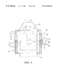
- FIG. 5 is a cross-sectional view through an exemplary reactor assembly having a plurality of stacked cells including insulating plates, spacers and electrode carrying plates as shown in FIG. 4;
- FIG. 6 is a fragmentary cross-sectional view from the plane of the line 5 — 5 of FIG. 5;
- FIG. 7 is a fragmentary cross-sectional view, from the plane of the line 6 — 6 of FIG. 5;
- FIG. 8 is a pictorial view of a monolithic reactor element of the type used in the reactor assembly of FIG. 5 and including stacked plates, insulators and spacers.
- numeral 10 generally indicates an exhaust treatment system for an automotive vehicle having a direct injection diesel engine 12 , or another engine operating with lean combustion, and including a non-thermal plasma reactor 14 formed in accordance with the invention.
- Reactor 14 is connected with a controller 16 that is supplied with electrical energy from a source 18 and provides high voltage, high frequency AC power to the reactor 14 .
- the diesel engine exhaust carries emissions of nitrogen oxides, hydrocarbons, nitrogen, oxygen, water, carbon monoxide, and carbon dioxide to the reactor 14 .
- a non-thermal plasma developed in the reactor by the applied AC voltage converts the emissions to nitrogen dioxide, metastables, partially oxidized hydrocarbons, oxygen, water, nitrogen, carbon monoxide, and carbon dioxide from the reactor.
- These emissions are passed to a catalytic converter 20 , which completes the partial reactions to result primarily in nitrogen, water, carbon dioxide and oxygen. Conversion of the nitrogen oxides, in the diesel engine exhaust, depends greatly on the efficiency of the reaction in the NTP reactor 14 , which is constructed in accordance with the teachings of the present invention.
- Cell 22 includes a first alumina plate 24 having printed on one side thereof a generally rectangular silver electrode 26 having a portion defining an inwardly curved hollow 29 and having a narrow connector 27 extending to one edge 28 of the insulating alumina plate 24 . Hollow 29 spaces the electrode 26 at a distance from connector 37 suitable to prevent arc over.
- a pair of alumina spacers 30 engage the plate 24 .
- One spacer extends along the right edge 28 of the plate, and the other spacer 30 . extends along an opposite left edge 32 of the plate 24 .
- the lower sides of the spacers 30 are engaged by a plain alumina plate 34 which is, in turn, engaged on its opposite lower side by a printed plate 36 having printed on its upper surface a connector 37 to an electrode 38 of silver or the like having a portion defining a curved hollow 33 .
- the narrow connector 37 connects the electrode 38 with the edge 32 of the lower plate that is opposite to the edge 28 to which the electrode 26 of the plate 24 is connected.
- the corners of electrodes 26 , 38 are rounded to avoid creating focal points of voltage field lines that could concentrate energy and break down the insulation so that current could pass therethrough.
- each cell 22 is formed from the stack of plates 24 , 34 , and 36 , and spacers 30 between plates 24 and 34 provide a passage 39 through the cell between the spacers 30 . having a height equal to the thickness of the spacers 30 which, in the experimental embodiment shown, is about 1.5 mm.
- exhaust gas is passed through the passage 39 between the spacers 30 , while a high voltage alternating current is applied to the electrode 26 .
- Electrode 38 of the lower plate is grounded, so that an alternating voltage is applied between the electrodes 26 , 38 and is imposed upon the exhaust gas passing through the passage in the cell.
- the passage 39 is insulated from both electrodes by the high dielectric alumina plates.
- Plate 24 separates the charged electrode 36 from the passage 39 that is on the other, noncoated, side of plate 34 .
- Electrode 38 is insulated from the passage 39 by the uncoated plate or plain alumina plate 34 that is stacked between the coated electrode 38 and the passage 39 .
- the electrodes 26 and 38 arc extended through connectors 27 , 37 to opposite edges 28 , 32 of their respective plates where they may be electrically contacted by a conductor, for example, to charge electrode 26 with a high AC voltage and to ground electrode 38 , as is required for operation of the reactor cell.
- the connectors are made narrow to minimize power loss from the useless formation of plasma outside of the passages 39 and to reduce the precious metal content of the plates.
- the present electrodes are patterned having a portion defining an inwardly curved hollow 29 so as to provide a distance between the connector 37 and the electrode 26 sufficient to prevent arc over without diminishing performance.
- FICS. 2 A and 2 B provide a view of an electrode 26 a having connectors 27 A and 37 A in accordance with a previous design and electrode 26 of the present embodiment. As shown in FIG. 2B, the present invention provides the advantage of increased spacing between electrode 26 and connector 37 , thus reducing the opportunity for are over.
- Alternate electrode patterns sufficient to provide a distance suitable to prevent arc over may be employed, as desired, and are considered within the scope of the present invention. Previously, are overs were known to occur at about 5 k VAC rms (voltage alternating current root mean square). The present system eliminates arc overs at least until about 7 k VAC rms.
- plate 24 actually becomes the lower plate of the next cell above that shown.
- the new cell is, in turn, completed by an uncoated plate 34 laid above plate 24 , then a pair of spacers 30 and another grounded conductor plate 36 , 1 placed on top of the spacers to form the second cell.
- a stack of cells is created having alternate charged and grounded electrode plates to form a reactor element with a plurality of gas passages extending therethrough for exposure of the exhaust passages to the electrically created non-thermal plasma for assisting the reduction of NOx in the exhaust gases.
- Conductor 41 includes, in series, a connecting section 42 extending to one edge 44 of the plate 40 , a first electrode 46 connecting with section 42 and extending longitudinally along a large part of the right hand portion of the plate, intermediate sections 48 extending across the center of the plate at spaced locations and connecting with a second electrode 50 extending longitudinally along a large part of the left hand portion of the plate, and having an inwardly curved hollow 51 .
- Plate 40 is thus comprised of a high dielectric nonporous insulating material, in this case alumina, with a pair of dual large electrodes 46 , 50 painted on one surface in a pattern effective to prevent arc over and interconnected through a connecting section 42 with an external conductor, not shown, for electrically connecting the plate to a power source or to ground.
- the corners of the electrodes are curved and the widths of connecting and intermediate sections are minimized for the reasons discussed with regard to the FIG. 3 embodiment.
- FIGS. 5-7 there is shown a reactor element 52 formed by a stack of dual cells made with electrode plates 40 , as well as with plain plates 54 and spacers 56 . Note that, as assembled, the reactor cells form dual rows of vertically aligned passages 60 , each of which is disposed between a pair of electrodes, of which one is charged with high AC voltage and the other is grounded.
- each passage 60 is insulated from the nearest electrode by the thickness of one of the plates, either a plain plate 54 or the thickness of an electrode carrying plate 40 having its electrode painted on the opposite side of the plate from the associated passage.
- the plates and spacers are stacked in the order of: first, a plain plate 54 on top; second, a charged electrode plate 40 R with its conductor 41 on the top of the plate; third, three laterally spaced spacers 56 , including two along opposite edges 64 , 62 of the plates, and one spacer 56 centered between the other two to separate the passage 60 into two laterally adjacent groups or rows; fourth, another plain plate 54 ; and fifth, another electrode carrying plate 40 L having its conductor 41 painted on the top side of the plate and insulated from the passage above by the plain plate stacked above plate 40 L.
- the plates 40 R and 40 L are identical except as to the position or orientation of the plates 40 R and 40 L in the stack of plates making up the reactor element 52 .
- the plates 40 R are positioned so that their conductors 41 connect through sections 42 with the right hand edge 62 (see FIG. 5) of the element 52
- the alternate plates 40 L are positioned so that their conductors 41 extend through sections 42 to the left hand edge 64 of the reactor element 52 .
- the alternate plates 40 R, 40 L are identical plates 40 that differ only in that they are positioned so that the plates identified as 40 R have their connecting sections extending to the right hand edge 62 while the other plates 40 L having their connecting sections extending to the left hand edge 64 of the reactor element.
- FIGS. 5 and 6 illustrate that the left hand edge 64 of the reactor element includes a vertical conductor 66 which is painted or otherwise applied to the stack of plates making up the reactor element. Conductor 66 extends vertically into electrical contact with the connecting sections 42 of all of the left hand extending plates 40 L in the stack. In like manner, a similar vertical conductor 68 is applied along the right hand edge 62 of the reactor element 52 and is in electrical contact with all of the right hand edge extending plates 40 R.
- the individual electrodes 46 , 50 shown in the figures are generally aligned with the associated passages 60 and extend over a substantial portion of their length, but, except for their points of connection with the outer edges of the reactor element and with the other electrode 46 , they do not extend into the areas occupied by the spacers 56 .
- the pattern of the conductors 41 painted on the various plates makes efficient use of the conductive material by applying it only where needed to form electrodes that energize the various gas passages 60 or to conduct electrical charges to and between the electrodes 46 , 50 formed on the plate.
- a reactor assembly 70 including a high temperature housing 72 enclosing a dielectric mat 74 electrically insulating and forming a shock mount supporting, within the housing, a reactor element 52 as illustrated in FIG. 5 .
- the housing 72 is preferably provided with inlet and outlet cones 76 , 78 , respectively, for connecting the housing 72 in a vehicle exhaust system and directing the exhaust gases through the passages 60 within the reactor element 52 .
- the housing 72 is provided with a threaded boss 80 in which is mounted an insulated connector 82 having an internal conductor 84 that connects with a spring 86 which in turn contacts the vertical conductor 68 extending vertically along the right hand side or edge 62 of the reactor element 52 .
- Conductor 68 connects through sections 42 of conductors 41 of each plate 40 R with the electrodes 46 , 50 on each plate.
- the alternate plates 40 L have their conductors 41 extending through connecting sections 42 into contact with the vertical conductor 66 extending along the left hand side of the reactor element 52 .
- Conductor 66 is engaged by a spring 88 which extends between the conductor 66 and an outer portion 90 of the housing 72 to ground the conductors 41 of plates 40 L to the housing, which is in use grounded to the electrical ground of the associated vehicle in which it is installed.
- exhaust flow passes through the reactor assembly 70 from the cone 76 through the internal passages 60 and out through the cone 78 to the following catalytic converter, the operation being as described in connection with the system shown in FIG. 1 .
- any suitable materials may be used which have the properties required to carry out the desired functions.
- the passages through the element and the associated insulating plates are made thin so that the distance between the electrodes above and below each passage are made small. This allows the development of an effective level of non-thermal plasma with voltages reduced to a range that can be provided in a vehicle mounted reactor assembly.
- the insulating plates must prevent the passage of electric current through the passages which would cause an arc, so material with a high dielectric strength is needed. Thus, high density alumina is preferred, but other insulating materials may also be suitable.
- Conductive silver or platinum ink baked onto the insulating plates is preferred for conductors and electrodes because it applies as a thin layer and avoids a need for separate wires or connectors. However, other forms of conductors could be used, if desired.
- the electrodes are coated in a pattern that spaces the electrode and connector at a distance suitable to prevent are over.
- the preferred embodiment described herein provides an electrode pattern of generally rectangular shape having an inwardly curved hollow (i.e., notch or cutaway portion) at the end opposite the connector end.
- Various alternate patterns may of course be employed, if desired, to achieve the present optimum electrode-connector spacing, and are considered within the scope of the present invention.
- the dielectric mat surrounding the element in a reactor assembly may be of ceramic fiber paper, expandable mica or any suitable material with a high dielectric strength and strength under exhaust reactor gas temperatures.
Abstract
An NOx reducing exhaust treatment system includes a non-thermal plasma reactor assembly which initiates NOx reduction reactions that are completed by a catalytic converter downstream of the reactor in the system. The reactor assembly includes a monolithic reactor element formed of insulating plates and spacers made of high dielectric material, such as alumina. Some of the plates carry electrodes and connecting conductors which may be painted on with conductive ink and baked on as a surface coating. The electrodes are patterned to provide a distance between the electrodes and the connectors of alternate electrodes that is sufficient to prevent arc over. The plates and spacers form a plurality of thin gas passages each lying between a pair of electrodes, one to be charged with an AC voltage and the other grounded to impress the alternating voltage across each passage. The electrodes are insulated from the passages by the thin insulating plates forming the passages so that no current flows between the electrodes. Instead, the voltage creates a non-thermal plasma in the passages that increases the activity of electrons in the exhaust gases and initiates breakdown of the NOx and other reaction products in the gases. The reactions are then completed in a downstream catalytic converter, resulting in reduced emissions of NOx as well as other controlled emissions in the treated exhaust gases.
Description
The present application is a continuation-in-part of U.S. patent application Ser. No. 09/268,496 filed Mar. 11, 1999 for “Non-thermal Plasma Exhaust NOx Reactor,” which is hereby incorporated by reference herein in its entirety.
This invention relates to reactors for chemical reduction of nitrogen oxide (NOx) emissions in the exhaust gases of automotive engines, particularly diesel and other engines operating with lean air fuel mixtures that produce relatively high emission of NOx. More particularly, the invention pertains to an improved non-thermal plasma reactor and system for use with diesel engines and the like.
In recent years, non-thermal plasma generated in a packed bed reactor has been shown to be effective in reducing nitric oxides (NOx) produced by power plants and standby generators. These units usually have a reducing agent, such as urea, to enhance the conversion efficiency. The packed bed reactor consists essentially of a high voltage center electrode inserted into a cylinder of dielectric material, usually a form of glass or quartz.
An outside or ground electrode is formed by a coating of metal in various forms, including tape, flame spray, mesh, etc. The space between the center electrode and the inside diameter of the dielectric tube is filled or packed with small diameter glass beads. When high voltage alternating current is applied to the center electrode, the surfaces of the beads go into corona, producing a highly reactive and selective surface for inducing the desired reaction in the gas.
Unfortunately, the packed bed design with its loose beads and glass dielectric is impractical for use in the conditions found in a mobile emitter, such as a car or truck. The vibration and wide temperature swings of the vehicle system would damage the packed bed and the necessary temperature and vibration isolation needed to make it survive would not be cost effective.
A reactor for use with diesel engines and other engines operating with lean air fuel mixtures is disclosed in commonly assigned U.S. patent application Ser. No. 09/268,496 entitled “Non-thermal Plasma Exhaust NOx Reactor.” Disclosed therein is a reactor element comprising high dielectric, nonporous, high temperature insulating means defining a group of relatively thin stacked cells forming gas passages and separated by the insulating means. Alternate ground and charge carrying electrodes in the insulating means on opposite sides of the cells are disposed close to, but electrically insulated from, the cells by the insulating means. The electrodes may be silver or platinum material coated onto alumina plates. Conductive ink is sandwiched between two thin nonporous alumina plates or other suitable insulating plates to prevent arcing while providing a stable electrode spacing for a uniform electric field
There remains a need in the art to minimize the potential failure condition whereby high voltage could leak away from the reactor due to the short distance between the electrode and the connector. There further remains a need for an improved reactor that can offer the structural integrity of current automotive catalysts while providing improved high voltage control.
The present invention provides a monolithic non-thermal plasma reactor (MPR) in which the electrodes may be silver or platinum material coated onto alumina in a pattern that establishes a separation between the electrodes and the connectors of alternate electrodes suitable to prevent voltage leakage. Conductive ink is sandwiched between two thin nonporous alumina plates or other suitable insulating plates. This prevents arcing while providing stable electrode spacing needed for a uniform electric field.
Opposite polarity plates are retained by a dielectric structure, such as a honeycomb extrudate common in today's automotive catalytic converters. The extrudate may be coated or can be made of a catalytic material whose structure and chemical composition provide active sites for NOx reduction. Alternatively, a downstream catalytic converter may be provided in the system to complete the conversion of NOx to nitrogen and oxygen. The use of the catalyst significantly reduces the power required to complete the conversion of NOx.
In the MPR, each of the parallel plate pairs forms a cell. These cells are stacked in order to subject the exhaust gases to as much catalyst surface in plasma as is possible within a minimal volume. By reducing the electrode spacing of the cells, lower voltages can be used to create a corona. This minimizes the extraordinary safeguards and barriers needed to contain very high (15,000 plus) voltages of the packed bed reactors, proving a simpler and lower cost electrical delivery system.
The use of electrode coated plates may be made by the use of ceramic inks and printing processes which provides the simplicity of making connections and conductors through conventional screening processes. This eliminates the need for wires and connectors and their associated assembly complexity and unreliability.
These and other features and advantages of the invention will be more fully understood from the following description of certain specific embodiments of the invention taken together with the accompanying drawings.
In the drawings:
FIG. 1 is a schematic diagram showing a non-thermal plasma (NTP) system including a non-thermal plasma reactor of the invention for the conversion of NOx in an automotive vehicle;
FIG. 2A is a plan view of a single alumina plate showing an electrode coated in accordance with prior electrode design and FIG. 2B is a plan view of a single alumina plate showing an electrode in accordance with a preferred embodiment of the present invention;
FIG. 3 is an exploded pictorial view showing the construction of a single cell of an experimental NTP reactor;
FIG. 4 is a plan view of a single alumina plate having electrodes coated on one surface, in a pattern that spaces the electrode and connector at a distance suitable to prevent arc over, for reaction of NOx in adjacent cells of an improved reactor element;
FIG. 5 is a cross-sectional view through an exemplary reactor assembly having a plurality of stacked cells including insulating plates, spacers and electrode carrying plates as shown in FIG. 4;
FIG. 6 is a fragmentary cross-sectional view from the plane of the line 5—5 of FIG. 5;
FIG. 7 is a fragmentary cross-sectional view, from the plane of the line 6—6 of FIG. 5; and
FIG. 8 is a pictorial view of a monolithic reactor element of the type used in the reactor assembly of FIG. 5 and including stacked plates, insulators and spacers.
Referring first to FIG. 1 of the drawings in detail, numeral 10 generally indicates an exhaust treatment system for an automotive vehicle having a direct injection diesel engine 12, or another engine operating with lean combustion, and including a non-thermal plasma reactor 14 formed in accordance with the invention.
Referring now to FIG. 3, there is shown in exploded form a single cell 22 of an experimental form of a NTP reactor element which was successfully tested, demonstrating a conversion efficiency for NOx in excess of fifty percent. Cell 22 includes a first alumina plate 24 having printed on one side thereof a generally rectangular silver electrode 26 having a portion defining an inwardly curved hollow 29 and having a narrow connector 27 extending to one edge 28 of the insulating alumina plate 24. Hollow 29 spaces the electrode 26 at a distance from connector 37 suitable to prevent arc over.
Below the alumina plate 24 on the unprinted side thereof, a pair of alumina spacers 30 engage the plate 24. One spacer extends along the right edge 28 of the plate, and the other spacer 30. extends along an opposite left edge 32 of the plate 24. The lower sides of the spacers 30 are engaged by a plain alumina plate 34 which is, in turn, engaged on its opposite lower side by a printed plate 36 having printed on its upper surface a connector 37 to an electrode 38 of silver or the like having a portion defining a curved hollow 33. The narrow connector 37 connects the electrode 38 with the edge 32 of the lower plate that is opposite to the edge 28 to which the electrode 26 of the plate 24 is connected. The corners of electrodes 26, 38 are rounded to avoid creating focal points of voltage field lines that could concentrate energy and break down the insulation so that current could pass therethrough.
In assembly, each cell 22 is formed from the stack of plates 24, 34, and 36, and spacers 30 between plates 24 and 34 provide a passage 39 through the cell between the spacers 30. having a height equal to the thickness of the spacers 30 which, in the experimental embodiment shown, is about 1.5 mm.
In operation of the cell in a stack of similar cells, exhaust gas is passed through the passage 39 between the spacers 30, while a high voltage alternating current is applied to the electrode 26. Electrode 38 of the lower plate is grounded, so that an alternating voltage is applied between the electrodes 26, 38 and is imposed upon the exhaust gas passing through the passage in the cell. The passage 39 is insulated from both electrodes by the high dielectric alumina plates. Plate 24 separates the charged electrode 36 from the passage 39 that is on the other, noncoated, side of plate 34. Electrode 38 is insulated from the passage 39 by the uncoated plate or plain alumina plate 34 that is stacked between the coated electrode 38 and the passage 39. This insulation prevents any flow of electricity between the electrodes 26, 38 and thus prevents an actual arc from passing, between the electrodes, Thus, there is no current flow and the exhaust gas is not heated by the plasma reaction within the passage. However, the alternating voltage impressed upon the passage does provide electric energy which increases the activity of electrons in the exhaust gas within the passage and thus initiates the chemical reactions which begin the reduction of NO to nitrogen and oxygen. The electrodes 26 and 38 arc extended through connectors 27, 37 to opposite edges 28, 32 of their respective plates where they may be electrically contacted by a conductor, for example, to charge electrode 26 with a high AC voltage and to ground electrode 38, as is required for operation of the reactor cell. The connectors are made narrow to minimize power loss from the useless formation of plasma outside of the passages 39 and to reduce the precious metal content of the plates.
When too short a distance is provided between the electrodes and the connectors, a potential failure condition is presented where high voltage could leak away from the reactor. The present electrodes are patterned having a portion defining an inwardly curved hollow 29 so as to provide a distance between the connector 37 and the electrode 26 sufficient to prevent arc over without diminishing performance. FICS. 2A and 2B provide a view of an electrode 26 a having connectors 27A and 37A in accordance with a previous design and electrode 26 of the present embodiment. As shown in FIG. 2B, the present invention provides the advantage of increased spacing between electrode 26 and connector 37, thus reducing the opportunity for are over. Alternate electrode patterns sufficient to provide a distance suitable to prevent arc over may be employed, as desired, and are considered within the scope of the present invention. Previously, are overs were known to occur at about 5 k VAC rms (voltage alternating current root mean square). The present system eliminates arc overs at least until about 7 k VAC rms.
In constructing a stack of cells to provide a reactor element, plate 24 actually becomes the lower plate of the next cell above that shown. The new cell is, in turn, completed by an uncoated plate 34 laid above plate 24, then a pair of spacers 30 and another grounded conductor plate 36, 1placed on top of the spacers to form the second cell. In this manner, a stack of cells is created having alternate charged and grounded electrode plates to form a reactor element with a plurality of gas passages extending therethrough for exposure of the exhaust passages to the electrically created non-thermal plasma for assisting the reduction of NOx in the exhaust gases.
Referring now to FIG. 4, there is shown another embodiment of alumina plate 40 having painted on the near side thereof a conductor 41. such as silver or platinum. Conductor 41 includes, in series, a connecting section 42 extending to one edge 44 of the plate 40, a first electrode 46 connecting with section 42 and extending longitudinally along a large part of the right hand portion of the plate, intermediate sections 48 extending across the center of the plate at spaced locations and connecting with a second electrode 50 extending longitudinally along a large part of the left hand portion of the plate, and having an inwardly curved hollow 51. Plate 40 is thus comprised of a high dielectric nonporous insulating material, in this case alumina, with a pair of dual large electrodes 46, 50 painted on one surface in a pattern effective to prevent arc over and interconnected through a connecting section 42 with an external conductor, not shown, for electrically connecting the plate to a power source or to ground. The corners of the electrodes are curved and the widths of connecting and intermediate sections are minimized for the reasons discussed with regard to the FIG. 3 embodiment.
Referring now to FIGS. 5-7, there is shown a reactor element 52 formed by a stack of dual cells made with electrode plates 40, as well as with plain plates 54 and spacers 56. Note that, as assembled, the reactor cells form dual rows of vertically aligned passages 60, each of which is disposed between a pair of electrodes, of which one is charged with high AC voltage and the other is grounded.
As before, each passage 60 is insulated from the nearest electrode by the thickness of one of the plates, either a plain plate 54 or the thickness of an electrode carrying plate 40 having its electrode painted on the opposite side of the plate from the associated passage. The plates and spacers are stacked in the order of: first, a plain plate 54 on top; second, a charged electrode plate 40R with its conductor 41 on the top of the plate; third, three laterally spaced spacers 56, including two along opposite edges 64, 62 of the plates, and one spacer 56 centered between the other two to separate the passage 60 into two laterally adjacent groups or rows; fourth, another plain plate 54; and fifth, another electrode carrying plate 40L having its conductor 41 painted on the top side of the plate and insulated from the passage above by the plain plate stacked above plate 40L.
As is best illustrated in FIGS. 6 and 7, the plates 40R and 40L are identical except as to the position or orientation of the plates 40R and 40L in the stack of plates making up the reactor element 52. As is apparent from the enlarged cross section of FIG. 6, the plates 40R are positioned so that their conductors 41 connect through sections 42 with the right hand edge 62 (see FIG. 5) of the element 52, while the alternate plates 40L are positioned so that their conductors 41 extend through sections 42 to the left hand edge 64 of the reactor element 52. Thus, the alternate plates 40R, 40L are identical plates 40 that differ only in that they are positioned so that the plates identified as 40R have their connecting sections extending to the right hand edge 62 while the other plates 40L having their connecting sections extending to the left hand edge 64 of the reactor element.
FIGS. 5 and 6 illustrate that the left hand edge 64 of the reactor element includes a vertical conductor 66 which is painted or otherwise applied to the stack of plates making up the reactor element. Conductor 66 extends vertically into electrical contact with the connecting sections 42 of all of the left hand extending plates 40L in the stack. In like manner, a similar vertical conductor 68 is applied along the right hand edge 62 of the reactor element 52 and is in electrical contact with all of the right hand edge extending plates 40R.
From FIGS. 6 and 7, it is observed that the individual electrodes 46, 50 shown in the figures, are generally aligned with the associated passages 60 and extend over a substantial portion of their length, but, except for their points of connection with the outer edges of the reactor element and with the other electrode 46, they do not extend into the areas occupied by the spacers 56. Thus, the pattern of the conductors 41 painted on the various plates makes efficient use of the conductive material by applying it only where needed to form electrodes that energize the various gas passages 60 or to conduct electrical charges to and between the electrodes 46, 50 formed on the plate.
Referring now to FIG. 8 of the drawings, there is shown a reactor assembly 70 including a high temperature housing 72 enclosing a dielectric mat 74 electrically insulating and forming a shock mount supporting, within the housing, a reactor element 52 as illustrated in FIG. 5. The housing 72 is preferably provided with inlet and outlet cones 76, 78, respectively, for connecting the housing 72 in a vehicle exhaust system and directing the exhaust gases through the passages 60 within the reactor element 52.
To provide the needed high voltage AC power to the plates 40R of the element 52, the housing 72 is provided with a threaded boss 80 in which is mounted an insulated connector 82 having an internal conductor 84 that connects with a spring 86 which in turn contacts the vertical conductor 68 extending vertically along the right hand side or edge 62 of the reactor element 52. Conductor 68 connects through sections 42 of conductors 41 of each plate 40R with the electrodes 46, 50 on each plate. In turn, the alternate plates 40L have their conductors 41 extending through connecting sections 42 into contact with the vertical conductor 66 extending along the left hand side of the reactor element 52. Conductor 66 is engaged by a spring 88 which extends between the conductor 66 and an outer portion 90 of the housing 72 to ground the conductors 41 of plates 40L to the housing, which is in use grounded to the electrical ground of the associated vehicle in which it is installed.
In operation, exhaust flow passes through the reactor assembly 70 from the cone 76 through the internal passages 60 and out through the cone 78 to the following catalytic converter, the operation being as described in connection with the system shown in FIG. 1.
In making a reactor element according to the invention, any suitable materials may be used which have the properties required to carry out the desired functions. The passages through the element and the associated insulating plates are made thin so that the distance between the electrodes above and below each passage are made small. This allows the development of an effective level of non-thermal plasma with voltages reduced to a range that can be provided in a vehicle mounted reactor assembly. The insulating plates must prevent the passage of electric current through the passages which would cause an arc, so material with a high dielectric strength is needed. Thus, high density alumina is preferred, but other insulating materials may also be suitable. Conductive silver or platinum ink baked onto the insulating plates is preferred for conductors and electrodes because it applies as a thin layer and avoids a need for separate wires or connectors. However, other forms of conductors could be used, if desired. The electrodes are coated in a pattern that spaces the electrode and connector at a distance suitable to prevent are over. The preferred embodiment described herein provides an electrode pattern of generally rectangular shape having an inwardly curved hollow (i.e., notch or cutaway portion) at the end opposite the connector end. Various alternate patterns may of course be employed, if desired, to achieve the present optimum electrode-connector spacing, and are considered within the scope of the present invention. Also, the dielectric mat surrounding the element in a reactor assembly may be of ceramic fiber paper, expandable mica or any suitable material with a high dielectric strength and strength under exhaust reactor gas temperatures.
While the invention has been described by reference to certain preferred embodiments, it should be understood that numerous changes could be made within the spirit and scope of the inventive concepts described. Accordingly, it is intended that the invention not be limited to the disclosed embodiments, but that it have the full scope permitted by the language of the following claims.
Claims (12)
1. A non-thermal plasma reactor element comprising a multi-cell stack, individual cells in said stack comprising:
a pair of first and second electrode plates each comprising a high dielectric insulating plate having a printed side and a non-printed side;
said printed side of said electrode plates including an electrode and a connector extending to one edge of said electrode plate, said connector being narrow relative to said electrode;
wherein said electrode plates are oriented such that said connector of said first electrode plate extends to a first edge of said cell and said connector of said second electrode plate extends to a second edge of said cell opposite said first edge, forming alternate ground and charge carrying electrodes;
said electrodes defining a pattern sufficient to establish a separation between said electrodes and connectors of alternate electrodes suitable to inhibit voltage leakage;
a pair of spacers, wherein upper surfaces of said spacers engage said non-printed side of said first electrode plate and lower surfaces of said spacers engage a non-printed high dielectric insulating plate disposed between said pair of spacers and said second electrode plate;
wherein said spacers form an exhaust gas passage between said first electrode plate and said non-printed insulating plate.
2. The element of claim 1 , wherein said insulating plates comprise alumina.
3. The element of claim 1 , wherein said electrodes have rounded corners.
4. The element of claim 1 , wherein said spacers and said insulating plates are configured to be as thin as possible to minimize the distance between said first and second electrode plates while still preventing passage of electric current through said exhaust gas passages.
5. The element of claim 1 , wherein a first spacer of said pair of spacers extends along a right edge of said first electrode plate and a second spacer of said pair of spacers extends along an opposite left edge of said first electrode plate.
6. The element of claim 1 , further comprising:
a third spacer disposed between said pair of spacers to provide two laterally adjacent groups of vertically aligned exhaust gas passages.
7. The element of claim 1 , wherein said printed side of said insulating plates comprises dual electrodes;
said dual electrodes including, in series, a first electrode having a connector extending to one edge of said insulating plate, a second electrode, and at least one intermediate section connecting said first electrode to said second electrode.
8. The element of claim 7 , wherein said dual electrodes have rounded corners.
9. The element of claim 7 , wherein said at least one intermediate section is narrow relative to said first and second electrodes.
10. The element of claim 7 , further comprising:
a third spacer disposed between said pair of spacers to provide two laterally adjacent groups of vertically aligned exhaust gas passages.
11. A non-thermal plasma reactor assembly containing the reactor element as in claim 1 and including:
a high temperature housing surrounding said reactor element and spaced therefrom by a dielectric mat supporting the element in said housing;
an insulated conductor connecting said charge carrying electrodes to an alternating voltage source;
an grounded conductor connecting said ground electrodes to ground; and
means for directing exhaust gas through said exhaust gas passages.
12. A reactor element as in claim 1 , wherein said electrode pattern comprises an inwardly curved un-printed hollow portion disposed at an edge of said electrode of said first electrode plate opposite said connector of said first electrode plate, whereby said hollow provides a separation between said electrode of said first electrode plate and said connector of said second electrode plate sufficient to prevent arc over without diminishing performance.
Priority Applications (1)
| Application Number | Priority Date | Filing Date | Title |
|---|---|---|---|
| US09/465,073 US6464945B1 (en) | 1999-03-11 | 1999-12-16 | Non-thermal plasma exhaust NOx reactor |
Applications Claiming Priority (2)
| Application Number | Priority Date | Filing Date | Title |
|---|---|---|---|
| US26849699A | 1999-03-11 | 1999-03-11 | |
| US09/465,073 US6464945B1 (en) | 1999-03-11 | 1999-12-16 | Non-thermal plasma exhaust NOx reactor |
Related Parent Applications (1)
| Application Number | Title | Priority Date | Filing Date |
|---|---|---|---|
| US26849699A Continuation-In-Part | 1999-03-11 | 1999-03-11 |
Publications (1)
| Publication Number | Publication Date |
|---|---|
| US6464945B1 true US6464945B1 (en) | 2002-10-15 |
Family
ID=23023267
Family Applications (1)
| Application Number | Title | Priority Date | Filing Date |
|---|---|---|---|
| US09/465,073 Expired - Fee Related US6464945B1 (en) | 1999-03-11 | 1999-12-16 | Non-thermal plasma exhaust NOx reactor |
Country Status (1)
| Country | Link |
|---|---|
| US (1) | US6464945B1 (en) |
Cited By (57)
| Publication number | Priority date | Publication date | Assignee | Title |
|---|---|---|---|---|
| US20010016179A1 (en) * | 1999-06-29 | 2001-08-23 | Delphi Technologies, Inc. | Design and method of manufacturing a plasma reactor for treating auto emissions - stacked shapes |
| US20020068025A1 (en) * | 2000-12-04 | 2002-06-06 | Foster Michael Ralph | Catalytic converter |
| US20020071791A1 (en) * | 2000-12-13 | 2002-06-13 | Foster Michael Ralph | Catalytic converter |
| US20020070127A1 (en) * | 2000-12-12 | 2002-06-13 | Young-Hoon Song | Catalyst reactor for processing hazardous gas using non-thermal plasma and dielectric heat and method threreof |
| US20020076363A1 (en) * | 2000-12-18 | 2002-06-20 | Nelson David Emil | Scaleable inter-digitized tine non-thermal plasma reactor |
| US20020076362A1 (en) * | 2000-12-15 | 2002-06-20 | Hardesty Jeffrey B. | Exhaust manifold with catalytic converter shell tube |
| US20020073697A1 (en) * | 2000-12-15 | 2002-06-20 | Jankowski Paul E. | Variable flow regulator for use with catalytic converters |
| US20020081244A1 (en) * | 2000-12-21 | 2002-06-27 | Roth Gregory Thomas | Integrated catalytic converter and flexible endcone assembly |
| US20020081242A1 (en) * | 2000-12-21 | 2002-06-27 | Labarge William J. | NOx control |
| US20020111266A1 (en) * | 2000-12-15 | 2002-08-15 | Labarge William J. | Nitrogen oxide catalyst |
| US20020131918A1 (en) * | 2000-11-16 | 2002-09-19 | Nelson David Emil | Edge-connected non-thermal plasma exhaust after-treatment device |
| US20020134666A1 (en) * | 2000-12-19 | 2002-09-26 | Hemingway Mark David | Non-thermal plasma reactor for lower power consumption |
| US20020168304A1 (en) * | 2001-05-09 | 2002-11-14 | Boehnke John C. | Devices for managing housing expansion in exhaust emission control devices |
| US20020172626A1 (en) * | 2001-05-21 | 2002-11-21 | Lesher Eric J. | Gas treatment device and system, and method for making the same |
| US20020174938A1 (en) * | 2001-04-25 | 2002-11-28 | Bob Xiaobin Li | Laminated co-fired sandwiched element for non-thermal plasma reactor |
| US20020192127A1 (en) * | 2001-06-14 | 2002-12-19 | Li Robert X. | Apparatus and method for retention of non-thermal plasma reactor |
| US20020192130A1 (en) * | 2001-06-14 | 2002-12-19 | Foster Michael R. | Apparatus and method for mat protection of non-thermal plasma reactor |
| US20030007907A1 (en) * | 2001-04-02 | 2003-01-09 | Nelson David Emil | Non-thermal plasma reactor substrate design-E-shape with low loss electrode pattern |
| US20030010017A1 (en) * | 2001-07-12 | 2003-01-16 | Myers Stephen J. | Catalytic converter with integral oxygen sensor |
| US20030030374A1 (en) * | 2001-08-03 | 2003-02-13 | Deepak Pai | Dielectric barrier discharge plasma reactor cell |
| US20030140495A1 (en) * | 2002-01-31 | 2003-07-31 | Hardesty Jeffrey B. | Exhaust emission control device manufacturing method |
| US20030150709A1 (en) * | 2002-02-14 | 2003-08-14 | Labarge William J. | Non-thermal plasma reactor gas treatment system |
| US20030180199A1 (en) * | 2002-03-19 | 2003-09-25 | Yone-Seung Kim | Plasma reactor, production method thereof, and emission control apparatus of a vehicle |
| US20030180197A1 (en) * | 2002-02-06 | 2003-09-25 | Nunan John G. | Catalyst, an exhaust emission control device and a method of using the same |
| US20040052697A1 (en) * | 2002-09-18 | 2004-03-18 | Mcintosh Loel E. | Catalytic converter |
| US20040052699A1 (en) * | 2002-09-16 | 2004-03-18 | Michel Molinier | Exhaust treatment device |
| US20040086440A1 (en) * | 2002-10-31 | 2004-05-06 | Labarge William J. | Gas treatment device, methods for making and using the same, and a vehicle exhaust system |
| US20040093853A1 (en) * | 2002-11-08 | 2004-05-20 | Hemingway Mark D. | System and method for using nonthermal plasma reactors |
| WO2004054703A1 (en) * | 2002-12-13 | 2004-07-01 | Blue Planet Co., Ltd. | Plasma reactor and electrode plate used in the same |
| US6773681B1 (en) | 2000-08-03 | 2004-08-10 | Delphi Technologies, Inc. | Weldless flanged catalytic converters |
| US20040156759A1 (en) * | 2003-02-06 | 2004-08-12 | Foster Michael R. | Exhaust emission control device and system having reduced flow restriction |
| US6797241B2 (en) | 2000-12-20 | 2004-09-28 | Delphi Technologies, Inc. | Non-thermal plasma reactor having individually retained positive and negative reactor plates |
| US20040191132A1 (en) * | 2003-03-24 | 2004-09-30 | Desousa Egas | End cone assembly, exhaust emission control device and method of making thereof |
| US20040188238A1 (en) * | 2003-03-28 | 2004-09-30 | Hemingway Mark David | System and method for concurrent particulate and NOx control |
| US20040200209A1 (en) * | 2003-04-14 | 2004-10-14 | Kirwan John E. | Emissions reduction system and method |
| US20040208804A1 (en) * | 2001-08-25 | 2004-10-21 | Hall Stephen Ivor | Non-thermal plasma reactor |
| US20040258583A1 (en) * | 2003-06-18 | 2004-12-23 | Hardesty Jeffrey B. | Apparatus and method for manufacturing a catalytic converter |
| US20040259731A1 (en) * | 2003-06-19 | 2004-12-23 | Yan Jiyang | Methods for making a catalytic element, the catalytic element made therefrom, and catalyzed particulate filters |
| US20050030835A1 (en) * | 2003-08-08 | 2005-02-10 | John Dutkiewicz | Apparatus and method for displaying time and randomly-selected text information |
| DE10337901A1 (en) * | 2003-08-18 | 2005-03-24 | Audi Ag | Ammonia synthesis from hydrocarbons and air, especially for use in purifying combustion engine exhaust gases, by conversion to reformate gas followed by plasma-catalyzed reaction |
| US6878030B1 (en) | 1999-06-29 | 2005-04-12 | Delphi Technologies, Inc. | Plasma reactor for treating auto emissions—durable and low cost—curved shapes |
| US20050079112A1 (en) * | 2003-10-09 | 2005-04-14 | Li Bob Xiaobin | Surface discharge non-thermal plasma reactor and method |
| US20050138916A1 (en) * | 2003-12-29 | 2005-06-30 | Bonadies Joseph V. | Exhaust system and methods of reducing contaminants in an exhaust stream |
| US6916449B2 (en) | 2001-11-06 | 2005-07-12 | Delphi Technologies, Inc. | Exhaust treatment device and process for forming the same |
| US6919051B1 (en) | 1999-08-03 | 2005-07-19 | Delphi Technologies, Inc. | Low profile, integrated catalytic converter and flexible coupling assembly |
| US20050178107A1 (en) * | 2004-02-13 | 2005-08-18 | Rahul Mital | Plasma fuel converter NOx adsorber system for exhaust aftertreatment |
| US6946793B1 (en) | 1999-06-29 | 2005-09-20 | Delphi Technologies, Inc. | Plasma reactor design for treating auto emissions—durable and low cost |
| WO2005120684A1 (en) * | 2004-06-08 | 2005-12-22 | Korea Institute Of Machinery And Materials | Non-thermal plasma reactor for low pressure drop and low specific energy density |
| US20060075743A1 (en) * | 2003-12-29 | 2006-04-13 | Li Bob X | Exhaust treatment systems and methods for using the same |
| WO2006070838A1 (en) | 2004-12-27 | 2006-07-06 | Ngk Insulators, Ltd. | Plasma generating electrode and plasma reactor |
| US20060156985A1 (en) * | 2003-06-27 | 2006-07-20 | Yukio Miyairi | Apparatus for method of treating exhaust gas |
| US20060257299A1 (en) * | 2005-05-14 | 2006-11-16 | Lanz Douglas P | Apparatus and method for destroying volatile organic compounds and/or halogenic volatile organic compounds that may be odorous and/or organic particulate contaminants in commercial and industrial air and/or gas emissions |
| US20070160510A1 (en) * | 2001-07-12 | 2007-07-12 | Schultz Eric C | Gas sensor mounting boss and method of making |
| WO2008032934A1 (en) * | 2006-09-14 | 2008-03-20 | Cmtech Co., Ltd | Plasma reactor |
| US20100294653A1 (en) * | 2006-06-16 | 2010-11-25 | Randolf Kiefer | Device for electrochemical water preparation |
| US20150343380A1 (en) * | 2014-05-28 | 2015-12-03 | Edward Allen Zdunek | CO2 modification |
| WO2017150414A1 (en) | 2016-03-01 | 2017-09-08 | 日本特殊陶業株式会社 | Plasma reactor |
Citations (5)
| Publication number | Priority date | Publication date | Assignee | Title |
|---|---|---|---|---|
| US4152603A (en) * | 1976-10-06 | 1979-05-01 | Pavel Imris | Device for the production of ozone |
| US4842829A (en) * | 1985-11-19 | 1989-06-27 | Tohkai Kogyo Co., Ltd. | Deodorizing apparatus |
| US5236672A (en) * | 1991-12-18 | 1993-08-17 | The United States Of America As Represented By The United States Environmental Protection Agency | Corona destruction of volatile organic compounds and toxics |
| US5942195A (en) * | 1998-02-23 | 1999-08-24 | General Motors Corporation | Catalytic plasma exhaust converter |
| US6130182A (en) * | 1997-07-25 | 2000-10-10 | International Business Machines Corporation | Dielectric catalyst structures |
-
1999
- 1999-12-16 US US09/465,073 patent/US6464945B1/en not_active Expired - Fee Related
Patent Citations (5)
| Publication number | Priority date | Publication date | Assignee | Title |
|---|---|---|---|---|
| US4152603A (en) * | 1976-10-06 | 1979-05-01 | Pavel Imris | Device for the production of ozone |
| US4842829A (en) * | 1985-11-19 | 1989-06-27 | Tohkai Kogyo Co., Ltd. | Deodorizing apparatus |
| US5236672A (en) * | 1991-12-18 | 1993-08-17 | The United States Of America As Represented By The United States Environmental Protection Agency | Corona destruction of volatile organic compounds and toxics |
| US6130182A (en) * | 1997-07-25 | 2000-10-10 | International Business Machines Corporation | Dielectric catalyst structures |
| US5942195A (en) * | 1998-02-23 | 1999-08-24 | General Motors Corporation | Catalytic plasma exhaust converter |
Cited By (101)
| Publication number | Priority date | Publication date | Assignee | Title |
|---|---|---|---|---|
| US20010016179A1 (en) * | 1999-06-29 | 2001-08-23 | Delphi Technologies, Inc. | Design and method of manufacturing a plasma reactor for treating auto emissions - stacked shapes |
| US6946793B1 (en) | 1999-06-29 | 2005-09-20 | Delphi Technologies, Inc. | Plasma reactor design for treating auto emissions—durable and low cost |
| US6878348B2 (en) | 1999-06-29 | 2005-04-12 | Delphi Technologies, Inc. | Design and method of manufacturing a plasma reactor for treating auto emissions-stacked shapes |
| US6878030B1 (en) | 1999-06-29 | 2005-04-12 | Delphi Technologies, Inc. | Plasma reactor for treating auto emissions—durable and low cost—curved shapes |
| US6919051B1 (en) | 1999-08-03 | 2005-07-19 | Delphi Technologies, Inc. | Low profile, integrated catalytic converter and flexible coupling assembly |
| US6773681B1 (en) | 2000-08-03 | 2004-08-10 | Delphi Technologies, Inc. | Weldless flanged catalytic converters |
| US20020131918A1 (en) * | 2000-11-16 | 2002-09-19 | Nelson David Emil | Edge-connected non-thermal plasma exhaust after-treatment device |
| US6887440B2 (en) | 2000-11-16 | 2005-05-03 | Delphi Technologies, Inc. | Edge-connected non-thermal plasma exhaust after-treatment device |
| US20020068025A1 (en) * | 2000-12-04 | 2002-06-06 | Foster Michael Ralph | Catalytic converter |
| US6919052B2 (en) | 2000-12-04 | 2005-07-19 | Delphi Technologies, Inc. | Catalytic converter |
| US20020070127A1 (en) * | 2000-12-12 | 2002-06-13 | Young-Hoon Song | Catalyst reactor for processing hazardous gas using non-thermal plasma and dielectric heat and method threreof |
| US20020071791A1 (en) * | 2000-12-13 | 2002-06-13 | Foster Michael Ralph | Catalytic converter |
| US7093425B2 (en) | 2000-12-15 | 2006-08-22 | Delphi Technologies, Inc. | Variable flow regulator for use with catalytic converters |
| US20050160719A1 (en) * | 2000-12-15 | 2005-07-28 | Delphi Technologies, Inc. | Variable flow regulator for use with catalytic converters |
| US7241426B2 (en) | 2000-12-15 | 2007-07-10 | Delphi Technologies, Inc. | Exhaust manifold with catalytic converter shell tube |
| US20020073697A1 (en) * | 2000-12-15 | 2002-06-20 | Jankowski Paul E. | Variable flow regulator for use with catalytic converters |
| US20020111266A1 (en) * | 2000-12-15 | 2002-08-15 | Labarge William J. | Nitrogen oxide catalyst |
| US6887439B2 (en) | 2000-12-15 | 2005-05-03 | Delphi Technologies, Inc. | Variable flow regulator for use with catalytic converters |
| US20020076362A1 (en) * | 2000-12-15 | 2002-06-20 | Hardesty Jeffrey B. | Exhaust manifold with catalytic converter shell tube |
| US20020076363A1 (en) * | 2000-12-18 | 2002-06-20 | Nelson David Emil | Scaleable inter-digitized tine non-thermal plasma reactor |
| US6800256B2 (en) | 2000-12-18 | 2004-10-05 | Delphi Technologies, Inc. | Scaleable inter-digitized tine non-thermal plasma reactor |
| US20020134666A1 (en) * | 2000-12-19 | 2002-09-26 | Hemingway Mark David | Non-thermal plasma reactor for lower power consumption |
| US6835358B2 (en) | 2000-12-19 | 2004-12-28 | Delphi Technologies, Inc. | Non-thermal plasma reactor for lower power consumption |
| US6797241B2 (en) | 2000-12-20 | 2004-09-28 | Delphi Technologies, Inc. | Non-thermal plasma reactor having individually retained positive and negative reactor plates |
| US20020081242A1 (en) * | 2000-12-21 | 2002-06-27 | Labarge William J. | NOx control |
| US6824745B2 (en) | 2000-12-21 | 2004-11-30 | Delphi Technologies, Inc. | Integrated catalytic converter and flexible endcone assembly |
| US20050036927A1 (en) * | 2000-12-21 | 2005-02-17 | Delphi Technologies, Inc. | Integrated catalytic converter and flexible endcone assembly |
| US20020081244A1 (en) * | 2000-12-21 | 2002-06-27 | Roth Gregory Thomas | Integrated catalytic converter and flexible endcone assembly |
| US6887438B2 (en) | 2000-12-21 | 2005-05-03 | Delphi Technologies, Inc. | NOx control |
| US20030007907A1 (en) * | 2001-04-02 | 2003-01-09 | Nelson David Emil | Non-thermal plasma reactor substrate design-E-shape with low loss electrode pattern |
| US6821493B2 (en) | 2001-04-02 | 2004-11-23 | Delphi Technologies, Inc. | Non-thermal plasma reactor substrate design-E-shape with low loss electrode pattern |
| US6979892B2 (en) * | 2001-04-25 | 2005-12-27 | Delphi Technologies, Inc. | Laminated co-fired sandwiched element for non-thermal plasma reactor |
| US20020174938A1 (en) * | 2001-04-25 | 2002-11-28 | Bob Xiaobin Li | Laminated co-fired sandwiched element for non-thermal plasma reactor |
| US20020168304A1 (en) * | 2001-05-09 | 2002-11-14 | Boehnke John C. | Devices for managing housing expansion in exhaust emission control devices |
| US7179431B2 (en) | 2001-05-21 | 2007-02-20 | Delphi Technologies, Inc. | Gas treatment device and system, and method for making the same |
| US20020172626A1 (en) * | 2001-05-21 | 2002-11-21 | Lesher Eric J. | Gas treatment device and system, and method for making the same |
| US7078000B2 (en) | 2001-06-14 | 2006-07-18 | Delphi Technologies, Inc. | Apparatus and method for mat protection of non-thermal plasma reactor |
| US20020192127A1 (en) * | 2001-06-14 | 2002-12-19 | Li Robert X. | Apparatus and method for retention of non-thermal plasma reactor |
| US20020192130A1 (en) * | 2001-06-14 | 2002-12-19 | Foster Michael R. | Apparatus and method for mat protection of non-thermal plasma reactor |
| US6893617B2 (en) | 2001-06-14 | 2005-05-17 | Delphi Technologies, Inc. | Apparatus and method for retention of non-thermal plasma reactor |
| US7279140B2 (en) | 2001-07-12 | 2007-10-09 | Delphi Technologies, Inc. | Catalytic converter with integral oxygen sensor |
| US20070160510A1 (en) * | 2001-07-12 | 2007-07-12 | Schultz Eric C | Gas sensor mounting boss and method of making |
| US20030010017A1 (en) * | 2001-07-12 | 2003-01-16 | Myers Stephen J. | Catalytic converter with integral oxygen sensor |
| US8110152B2 (en) | 2001-07-12 | 2012-02-07 | Katcon Global S.A. | Gas sensor mounting boss and method of making |
| US20030030374A1 (en) * | 2001-08-03 | 2003-02-13 | Deepak Pai | Dielectric barrier discharge plasma reactor cell |
| US20040208804A1 (en) * | 2001-08-25 | 2004-10-21 | Hall Stephen Ivor | Non-thermal plasma reactor |
| US6916449B2 (en) | 2001-11-06 | 2005-07-12 | Delphi Technologies, Inc. | Exhaust treatment device and process for forming the same |
| US20030140495A1 (en) * | 2002-01-31 | 2003-07-31 | Hardesty Jeffrey B. | Exhaust emission control device manufacturing method |
| US7047641B2 (en) | 2002-01-31 | 2006-05-23 | Delphi Technologies, Inc. | Exhaust emission control device manufacturing method |
| US7041622B2 (en) | 2002-02-06 | 2006-05-09 | Delphi Technologies, Inc. | Catalyst, an exhaust emission control device and a method of using the same |
| US20030180197A1 (en) * | 2002-02-06 | 2003-09-25 | Nunan John G. | Catalyst, an exhaust emission control device and a method of using the same |
| US20030150709A1 (en) * | 2002-02-14 | 2003-08-14 | Labarge William J. | Non-thermal plasma reactor gas treatment system |
| US6852200B2 (en) | 2002-02-14 | 2005-02-08 | Delphi Technologies, Inc. | Non-thermal plasma reactor gas treatment system |
| US7211227B2 (en) * | 2002-03-19 | 2007-05-01 | Hyundai Motor Company | Plasma reactor, production method thereof, and emission control apparatus of a vehicle |
| US20030180199A1 (en) * | 2002-03-19 | 2003-09-25 | Yone-Seung Kim | Plasma reactor, production method thereof, and emission control apparatus of a vehicle |
| US7189375B2 (en) | 2002-09-16 | 2007-03-13 | Delphi Technologies, Inc. | Exhaust treatment device |
| US20040052699A1 (en) * | 2002-09-16 | 2004-03-18 | Michel Molinier | Exhaust treatment device |
| US20040052697A1 (en) * | 2002-09-18 | 2004-03-18 | Mcintosh Loel E. | Catalytic converter |
| US7094730B2 (en) | 2002-10-31 | 2006-08-22 | Delphi Technologies, Inc. | Gas treatment device, methods for making and using the same, and a vehicle exhaust system |
| US20040086440A1 (en) * | 2002-10-31 | 2004-05-06 | Labarge William J. | Gas treatment device, methods for making and using the same, and a vehicle exhaust system |
| US20040093853A1 (en) * | 2002-11-08 | 2004-05-20 | Hemingway Mark D. | System and method for using nonthermal plasma reactors |
| WO2004054703A1 (en) * | 2002-12-13 | 2004-07-01 | Blue Planet Co., Ltd. | Plasma reactor and electrode plate used in the same |
| US20060115391A1 (en) * | 2002-12-13 | 2006-06-01 | Kim Kyung W | Plasma reactor and and electrode plate used tin the same |
| US20040156759A1 (en) * | 2003-02-06 | 2004-08-12 | Foster Michael R. | Exhaust emission control device and system having reduced flow restriction |
| US7332137B2 (en) | 2003-03-24 | 2008-02-19 | Delphi Technologies, Inc. | End cone assembly, exhaust emission control device and method of making thereof |
| US20040191132A1 (en) * | 2003-03-24 | 2004-09-30 | Desousa Egas | End cone assembly, exhaust emission control device and method of making thereof |
| US20040188238A1 (en) * | 2003-03-28 | 2004-09-30 | Hemingway Mark David | System and method for concurrent particulate and NOx control |
| US20040200209A1 (en) * | 2003-04-14 | 2004-10-14 | Kirwan John E. | Emissions reduction system and method |
| US20040258583A1 (en) * | 2003-06-18 | 2004-12-23 | Hardesty Jeffrey B. | Apparatus and method for manufacturing a catalytic converter |
| US7462332B2 (en) | 2003-06-18 | 2008-12-09 | Delphi Technologies, Inc. | Apparatus and method for manufacturing a catalytic converter |
| US20070271786A1 (en) * | 2003-06-18 | 2007-11-29 | Delphi Technologies, Inc. | Apparatus and method for manufacturing a catalytic converter |
| US20040259731A1 (en) * | 2003-06-19 | 2004-12-23 | Yan Jiyang | Methods for making a catalytic element, the catalytic element made therefrom, and catalyzed particulate filters |
| US7465690B2 (en) | 2003-06-19 | 2008-12-16 | Umicore Ag & Co. Kg | Methods for making a catalytic element, the catalytic element made therefrom, and catalyzed particulate filters |
| US7700051B2 (en) * | 2003-06-27 | 2010-04-20 | Ngk Insulators, Ltd. | Apparatus and method of treating exhaust gas |
| US20060156985A1 (en) * | 2003-06-27 | 2006-07-20 | Yukio Miyairi | Apparatus for method of treating exhaust gas |
| US20050030835A1 (en) * | 2003-08-08 | 2005-02-10 | John Dutkiewicz | Apparatus and method for displaying time and randomly-selected text information |
| DE10337901A1 (en) * | 2003-08-18 | 2005-03-24 | Audi Ag | Ammonia synthesis from hydrocarbons and air, especially for use in purifying combustion engine exhaust gases, by conversion to reformate gas followed by plasma-catalyzed reaction |
| US20050079112A1 (en) * | 2003-10-09 | 2005-04-14 | Li Bob Xiaobin | Surface discharge non-thermal plasma reactor and method |
| US7188469B2 (en) | 2003-12-29 | 2007-03-13 | Delphi Technologies, Inc. | Exhaust system and methods of reducing contaminants in an exhaust stream |
| US20060075743A1 (en) * | 2003-12-29 | 2006-04-13 | Li Bob X | Exhaust treatment systems and methods for using the same |
| US7240484B2 (en) | 2003-12-29 | 2007-07-10 | Delphi Technologies, Inc. | Exhaust treatment systems and methods for using the same |
| US20050138916A1 (en) * | 2003-12-29 | 2005-06-30 | Bonadies Joseph V. | Exhaust system and methods of reducing contaminants in an exhaust stream |
| US20050178107A1 (en) * | 2004-02-13 | 2005-08-18 | Rahul Mital | Plasma fuel converter NOx adsorber system for exhaust aftertreatment |
| US7377101B2 (en) | 2004-02-13 | 2008-05-27 | Fleetguard, Inc. | Plasma fuel converter NOx adsorber system for exhaust aftertreatment |
| WO2005120684A1 (en) * | 2004-06-08 | 2005-12-22 | Korea Institute Of Machinery And Materials | Non-thermal plasma reactor for low pressure drop and low specific energy density |
| US20070247076A1 (en) * | 2004-12-27 | 2007-10-25 | Ngk Insulators, Ltd. | Plasma generating electrode and plasma reactor |
| EP1835789A1 (en) * | 2004-12-27 | 2007-09-19 | Ngk Insulators, Ltd. | Plasma generating electrode and plasma reactor |
| EP1835789A4 (en) * | 2004-12-27 | 2010-02-24 | Ngk Insulators Ltd | Plasma generating electrode and plasma reactor |
| WO2006070838A1 (en) | 2004-12-27 | 2006-07-06 | Ngk Insulators, Ltd. | Plasma generating electrode and plasma reactor |
| US20060257299A1 (en) * | 2005-05-14 | 2006-11-16 | Lanz Douglas P | Apparatus and method for destroying volatile organic compounds and/or halogenic volatile organic compounds that may be odorous and/or organic particulate contaminants in commercial and industrial air and/or gas emissions |
| US8105546B2 (en) * | 2005-05-14 | 2012-01-31 | Air Phaser Environmental Ltd. | Apparatus and method for destroying volatile organic compounds and/or halogenic volatile organic compounds that may be odorous and/or organic particulate contaminants in commercial and industrial air and/or gas emissions |
| US20100294653A1 (en) * | 2006-06-16 | 2010-11-25 | Randolf Kiefer | Device for electrochemical water preparation |
| US20100192542A1 (en) * | 2006-09-14 | 2010-08-05 | Hung Sik Min | Plasma Reactor |
| EP2069047A4 (en) * | 2006-09-14 | 2011-09-14 | Cmtech Co Ltd | Plasma reactor |
| EP2069047A1 (en) * | 2006-09-14 | 2009-06-17 | Cmtech Co., Ltd | Plasma reactor |
| WO2008032934A1 (en) * | 2006-09-14 | 2008-03-20 | Cmtech Co., Ltd | Plasma reactor |
| US8128884B2 (en) * | 2006-09-14 | 2012-03-06 | Cmtech Co., Ltd. | Plasma reactor |
| US20150343380A1 (en) * | 2014-05-28 | 2015-12-03 | Edward Allen Zdunek | CO2 modification |
| WO2017150414A1 (en) | 2016-03-01 | 2017-09-08 | 日本特殊陶業株式会社 | Plasma reactor |
| US20190055869A1 (en) * | 2016-03-01 | 2019-02-21 | Ngk Spark Plug Co., Ltd. | Plasma reactor |
| US10450916B2 (en) * | 2016-03-01 | 2019-10-22 | Ngk Spark Plug Co., Ltd. | Plasma reactor |
Similar Documents
| Publication | Publication Date | Title |
|---|---|---|
| US6464945B1 (en) | Non-thermal plasma exhaust NOx reactor | |
| US6338827B1 (en) | Stacked shape plasma reactor design for treating auto emissions | |
| US6537507B2 (en) | Non-thermal plasma reactor design and single structural dielectric barrier | |
| US6423190B2 (en) | Pulse density modulation for uniform barrier discharge in a nonthermal plasma reactor | |
| EP0553942B1 (en) | Core for a catalytic converter | |
| US6354903B1 (en) | Method of manufacture of a plasma reactor with curved shape for treating auto emissions | |
| EP1219340B1 (en) | Non-thermal plasma reactor for lower power consumption | |
| US8128884B2 (en) | Plasma reactor | |
| US7163663B2 (en) | Reactor for plasma assisted treatment of gaseous | |
| US7211227B2 (en) | Plasma reactor, production method thereof, and emission control apparatus of a vehicle | |
| EP0419906A1 (en) | Core element and core for electrically heatable catalytic converter | |
| JPS59136555A (en) | Ionizing device for internal combustion engine | |
| JPH05212293A (en) | Electrically heatable core for catalytic converter | |
| EP0735797B1 (en) | Electrically heatable honeycomb body | |
| EP1058577B1 (en) | A component for gas treatment | |
| US6692704B2 (en) | Non-thermal plasma reactor and method-structural conductor | |
| KR20020001736A (en) | Reactor for plasma assisted gas processing | |
| US6821493B2 (en) | Non-thermal plasma reactor substrate design-E-shape with low loss electrode pattern | |
| US20020131918A1 (en) | Edge-connected non-thermal plasma exhaust after-treatment device | |
| US6800256B2 (en) | Scaleable inter-digitized tine non-thermal plasma reactor | |
| AU669369B2 (en) | Core for catalytic converter | |
| US6946793B1 (en) | Plasma reactor design for treating auto emissions—durable and low cost | |
| US20040057880A1 (en) | Plasma reactor, method for its manufacture and a device for treating exhaust gases in internal combustion engines using the plasma reactor | |
| US6838058B2 (en) | Structural carrier non-thermal plasma reactor | |
| JP2002129947A (en) | Exhaust emission purifying device for internal combustion engine |
Legal Events
| Date | Code | Title | Description |
|---|---|---|---|
| AS | Assignment |
Owner name: DELPHI TECHNOLOGIES, INC., MICHIGAN Free format text: ASSIGNMENT OF ASSIGNORS INTEREST;ASSIGNOR:HEMINGWAY, MARK DAVID;REEL/FRAME:010914/0073 Effective date: 20000511 |
|
| FPAY | Fee payment |
Year of fee payment: 4 |
|
| REMI | Maintenance fee reminder mailed | ||
| LAPS | Lapse for failure to pay maintenance fees | ||
| STCH | Information on status: patent discontinuation |
Free format text: PATENT EXPIRED DUE TO NONPAYMENT OF MAINTENANCE FEES UNDER 37 CFR 1.362 |
|
| FP | Expired due to failure to pay maintenance fee |
Effective date: 20101015 |