US6441377B1 - System for exchanging and storing collimators for medical imaging devices - Google Patents
System for exchanging and storing collimators for medical imaging devices Download PDFInfo
- Publication number
- US6441377B1 US6441377B1 US09/448,567 US44856799A US6441377B1 US 6441377 B1 US6441377 B1 US 6441377B1 US 44856799 A US44856799 A US 44856799A US 6441377 B1 US6441377 B1 US 6441377B1
- Authority
- US
- United States
- Prior art keywords
- collimator
- arm
- collimators
- docking
- planar
- Prior art date
- Legal status (The legal status is an assumption and is not a legal conclusion. Google has not performed a legal analysis and makes no representation as to the accuracy of the status listed.)
- Expired - Fee Related
Links
- 238000002059 diagnostic imaging Methods 0.000 title abstract description 4
- 238000003032 molecular docking Methods 0.000 claims abstract description 38
- 238000003384 imaging method Methods 0.000 claims description 17
- 239000000969 carrier Substances 0.000 claims description 15
- 238000007373 indentation Methods 0.000 claims description 15
- 238000012546 transfer Methods 0.000 claims description 11
- 238000000034 method Methods 0.000 claims description 8
- 230000005855 radiation Effects 0.000 claims description 8
- 230000005355 Hall effect Effects 0.000 claims description 4
- 238000009206 nuclear medicine Methods 0.000 claims description 3
- 230000005251 gamma ray Effects 0.000 description 3
- 230000013011 mating Effects 0.000 description 2
- 238000007796 conventional method Methods 0.000 description 1
- 238000002955 isolation Methods 0.000 description 1
- 238000012986 modification Methods 0.000 description 1
- 230000004048 modification Effects 0.000 description 1
- 238000012552 review Methods 0.000 description 1
- 238000000926 separation method Methods 0.000 description 1
- 125000006850 spacer group Chemical group 0.000 description 1
Images


Classifications
-
- G—PHYSICS
- G21—NUCLEAR PHYSICS; NUCLEAR ENGINEERING
- G21K—TECHNIQUES FOR HANDLING PARTICLES OR IONISING RADIATION NOT OTHERWISE PROVIDED FOR; IRRADIATION DEVICES; GAMMA RAY OR X-RAY MICROSCOPES
- G21K1/00—Arrangements for handling particles or ionising radiation, e.g. focusing or moderating
- G21K1/02—Arrangements for handling particles or ionising radiation, e.g. focusing or moderating using diaphragms, collimators
-
- A—HUMAN NECESSITIES
- A61—MEDICAL OR VETERINARY SCIENCE; HYGIENE
- A61B—DIAGNOSIS; SURGERY; IDENTIFICATION
- A61B6/00—Apparatus for radiation diagnosis, e.g. combined with radiation therapy equipment
- A61B6/06—Diaphragms
-
- A—HUMAN NECESSITIES
- A61—MEDICAL OR VETERINARY SCIENCE; HYGIENE
- A61B—DIAGNOSIS; SURGERY; IDENTIFICATION
- A61B6/00—Apparatus for radiation diagnosis, e.g. combined with radiation therapy equipment
- A61B6/42—Apparatus for radiation diagnosis, e.g. combined with radiation therapy equipment with arrangements for detecting radiation specially adapted for radiation diagnosis
- A61B6/4208—Apparatus for radiation diagnosis, e.g. combined with radiation therapy equipment with arrangements for detecting radiation specially adapted for radiation diagnosis characterised by using a particular type of detector
- A61B6/4258—Apparatus for radiation diagnosis, e.g. combined with radiation therapy equipment with arrangements for detecting radiation specially adapted for radiation diagnosis characterised by using a particular type of detector for detecting non x-ray radiation, e.g. gamma radiation
Definitions
- the present invention relates generally to medical imaging systems, and more specifically to collimator exchange and storage systems for nuclear medicine imaging devices.
- Conventional nuclear medicine imaging systems include one or more gamma ray detectors supported by a gantry.
- the gantry may provide mechanical movement of the detectors such that the detectors can be positioned in different orientations around a patient's body. This allows image data to be acquired from varying angles around the patient.
- Some gamma ray imaging systems use the principle of absorptive collimation to form images.
- Collimators used in absorptive collimation project an image of the source onto a detector by allowing only the gamma rays traveling in certain directions to reach the detector.
- a collimator is mounted to the imaging surface of a detector to selectively filter radiation reaching the imaging surface.
- Different types of collimators can be used to generate images of varying quality and size.
- certain types of collimators are better suited for particular imaging studies. When different collimators are used during an imaging session or between imaging sessions, the collimators need to be substituted for one another because each detector is paired with only one collimator at a time.
- Exchanging collimators using conventional techniques and systems can be inconvenient and potentially dangerous due to the size and weight of the collimators.
- Many existing systems do not allow a patient to remain on the imaging table while an exchange is performed. Thus, in many existing systems, the patient must be moved off the imaging table when collimators need to be exchanged. However, repeatedly moving the patient to and from the imaging table whenever a collimator exchange is to be made can be time-consuming and harmful to the patient if the patient is in poor physical condition.
- many existing collimator exchange systems use carts which are heavily weighted when loaded, making it difficult for the operator to maneuver the carts into position. Such carts also occupy valuable floor space when in use or in storage.
- a desirable collimator exchange system would allow more imaging sessions to be performed while allowing the patient to remain on the imaging table and not wait any longer than necessary.
- a desirable collimator exchange system would also conserve floor space.
- the present invention provides an apparatus for exchanging collimators.
- the apparatus includes a first frame having a first receptacle and a second frame having a first docking member.
- a collimator can be attached to and removed from the first receptacle.
- the first docking member can be positioned adjacent to the first receptacle such that the first docking member can contact the collimator to remove the collimator from the first receptacle.
- the collimator is coupled to the first docking member while the collimator is removed from the first receptacle.
- the apparatus for exchanging collimators includes first and second transfer members which are movably coupled to a housing, and a rotatable delivery arm having a first collimator coupled to a first side and a second collimator coupled to a second side.
- the delivery arm rotates from a first position to a second position when one or both of the collimators are to be transferred to the transfer members.
- the transfer members are located adjacent to the collimators to be transferred.
- the transfer members can concurrently uncouple the first and second collimators from the delivery arm when the delivery arm is in the second position.
- the delivery arm stores the collimators in a vertical plane, such as adjacent to a wall, to reduce the amount of occupied floor space.
- the delivery arm can be manually or automatically operated.
- FIG. 1 shows a collimator exchanger in conjunction with a gantry system in accordance with the teachings of the present invention.
- FIG. 2A shows a collimator exchanger in accordance with the teachings of the present invention.
- FIG. 2B shows a side view of a collimator carrier used in the exchanger shown in FIG. 2 A.
- FIG. 3 shows a radiation detector and a collimator in exchange positions in accordance with the teachings of the present invention.
- FIG. 4A shows a side view of a detector and a collimator in exchange positions in accordance with the teachings of the present invention.
- FIGS. 4B-4C show side views of a detector and collimator after an exchange has been made in accordance with the teachings of the present invention.
- FIGS. 5A-5C show another collimator exchanger in accordance with the teachings of the present invention.
- FIGS. 5D-5E show close-up views of the collimator exchanger shown in FIGS. 5A-5C.
- FIG. 6 shows yet another collimator exchanger in accordance with the teachings of the present invention.
- FIGS. 7A-7D show the collimator exchanger shown in FIG. 6 in different positions as the exchanger moves to an exchange position in accordance with the teachings of the present invention.
- a system for exchanging collimator includes a delivery gate having a first receptacle and a positioning arm having a first docking member.
- a first collimator such as those used in absorptive collimation, can be attached to and removed from the first receptacle.
- the delivery gate is moved to an exchange area, the first docking member can be positioned adjacent to the first receptacle such that the first docking member can engage the first collimator to remove the first collimator from the first receptacle.
- the first collimator is secured to the first docking member while the first collimator is removed from the first receptacle.
- the first collimator provided by the delivery gate is transferred from the first receptacle to the first docking member.
- a second collimator can be attached to and removed from a second receptacle on the delivery gate.
- the delivery gate moves back to the exchange area to allow the positioning arm to move the first docking member adjacent to the first receptacle such that the first collimator can be transferred from the first docking member back to the first receptacle.
- the first docking member is free to engage the second collimator in a manner similar to that previously described with respect to the first collimator.
- the delivery gate of the present invention is capable of maintaining a thin profile to conserve space while an imaging session is being conducted. This permits less obtrusive storage of collimators.
- the thin profile capability also allows the delivery gate to be located near the positioning arm to reduce the time needed for an exchange. Furthermore, because different collimators can be carried by the delivery gate, multiple exchanges can be made using the same gate to reduce the time needed for all exchanges.
- the present invention also allows a patient to remain on the examination table during an exchange because the exchange area is located away from the patient. This particularly benefits fragile patients whose conditions would be exacerbated if they had to repeatedly move on and off the imaging table.
- FIG. 1 shows one embodiment of a collimator exchanger in conjunction with a gantry system.
- a gantry 100 is supported by legs 102 a - 102 d which rest on a level surface 103 , such as a floor.
- Gantry 100 includes a pair of positioning arms 104 a and 104 b slidably coupled to connecting arms 106 a and 106 b , respectively, which are coupled to housings 108 a and 108 b , respectively.
- Housings 108 a and 108 b are supported by guide rails 110 a and 110 b .
- Motors 112 a and 112 b independently drive housings 108 a and 108 b , respectively, along guide rails 110 a and 110 b .
- Positioning arms 104 a and 104 b are coupled to support frames 107 a and 107 b , respectively, which contain radiation detectors 105 a and 105 b , respectively.
- Support frames 107 a and 107 b can be rotated within positioning arms 104 a and 104 b , respectively, around the X-axis.
- the collimator exchanger shown in FIG. 1 includes two gates 114 and 116 .
- Gate 114 is shown in a home or closed position, and gate 116 is shown in an exchange or open position.
- An actuator 122 coupled to gate 116 controls the movement of gate 116 between its home position and its exchange position.
- Collimator carriers 120 are coupled to support blocks 121 which are fixed to gate 116 and gate 114 .
- Each carrier 120 houses a collimator 118 that can be paired with detectors 105 a and 105 b to conduct an imaging session.
- a gate When a gate is in its exchange position, it is oriented such that the face of a detector can be located substantially parallel to the face of a collimator.
- each carrier can house a different collimator.
- carriers that are adjacent to each other on opposite sides of a gate can house identical collimators.
- collimators 118 are exchanged from carriers 120 to frames 107 a and 107 b to pair with detectors 105 a and 105 b when different images of the patient are required. Before a new collimator is paired with a detector, a presently paired collimator is unpaired from the detector and moved back to its carrier.
- the exchanger is affixed to a wall 124 adjacent to gantry 100 .
- the locations of collimators 118 when gates 116 and 114 are in their exchange positions are known by control software which dictates the positioning of detectors 105 a and 105 b .
- the control software moves detectors 105 a and 105 b to positions determined by the known locations of collimators 118 .
- This provides automation of the actual collimator exchange upon an operator's selection of a desired collimator to be exchanged.
- the positioning of detectors 105 a and 105 b can be operator controlled or a combination of both operator and software controlled.
- FIG. 2A shows in isolation a collimator exchanger similar to that shown in FIG. 1 .
- Gate 116 is hinged to post 150 via hinge joints 132 a and 132 b .
- Gate 114 is similarly hinged to post 150 .
- Actuator arms 134 a and 134 b coupled to gate 116 are driven by a linear actuator drive motor 130 , which typically works in conjunction with a ramp up and down circuit.
- Gate 114 is coupled to another pair of actuator arms, similar to actuator arms 134 a and 134 b , which are also driven by a linear actuator drive motor (not shown), similar to motor 130 .
- the movement of gates 114 and 116 is controlled by switches (not shown) on each gate 114 and 116 that turn on or off the respective motors.
- switches not shown
- gates 114 and 116 can be moved independently.
- Control software may prevent gates 114 and 116 from moving to their exchange positions at the same time.
- carriers 120 are shown without collimators.
- the number of carriers 120 on gates 114 and 116 may vary depending on the size of gates 114 and 116 and/or the number of desired exchanges, among other factors.
- FIG. 2B shows a side view of one carrier 120 and gate 116 .
- Carrier 120 is coupled to support blocks 142 a and 142 b by pivot pins 144 a and 144 b , respectively.
- Support blocks 142 a and 142 b are attached to gate 116 .
- Spacers 146 a and 146 b provide separation between carrier 120 and support blocks 142 a and 142 b .
- the back surface of carrier 120 is also separated from gate 116 by gap 148 .
- Pivot pins 144 a and 144 b and gap 148 allow carrier 120 to rotate slightly to assist in aligning with detectors 105 a and 105 b when collimator 118 is to be exchanged. The rotational aligning of carrier 120 is helpful but not necessary to the present invention.
- carrier 120 can be directly coupled to gate 116 or integrally formed with gate 116 .
- FIG. 3 shows a radiation detector 205 within a support frame 207 , and a collimator 218 in exchange positions.
- a carrier 220 houses collimator 218 .
- Deflectable latches 222 (only one shown) coupled to edges 223 and 225 of carrier 220 help prevent collimator 218 from falling out of carrier 220 .
- the deflectable latches are spring loaded and have angled edges to more easily permit forcible deflection.
- Collimator 218 is also held in place within carrier 220 by lower pins 228 (only one shown) on carrier 220 mating with lower receptors 226 (only one shown) extending from opposite edges of collimator 218 .
- a gap 240 exists between the top edge of collimator 218 and the inner top edge of carrier 220 to provide clearance for the exchange of collimator 218 between carrier 220 and frame 207 .
- Pins 228 extend in the Z-direction from tabs 227 (only one shown) coupled to edges 223 and 225 of carrier 220 .
- Tabs 227 can be welded to, adhesively affixed to, or screwed onto edges 223 and 225 .
- Receptors 226 can be similarly coupled to collimator 218 .
- Upper receptors 224 coupled to opposite edges of collimator 218 are adapted to receive pins 234 (only one shown) extending from frame 207 .
- Pins 234 mate with receptors 224 when collimator 218 is to be exchanged from carrier 220 to frame 207 .
- Pins 230 also mate with receptors 226 to help secure collimator 218 to detector 205 .
- pins 230 are driven downward by linear motors 231 (only one shown) to effectively engage pins 230 with receptors 226 . It should be noted that the pins and receptors mate with each other in a male-female connection, as shown in later figures.
- the pins have embedded Hall effect sensors and the corresponding targets are located on the receptors that mate with the pins.
- Hall effect sensors at point 232 on pins 230 signal the position of pins 230 when they are not engaged with receptors 226 .
- Hall effect sensors embedded in the lower portion of pins 230 signal the engaged position of pins 230 .
- detector 205 is moved away from carrier 220 in the Y-direction such that collimator 218 deflects latches 222 and is removed from carrier 220 .
- the sensors are embedded in the receptors and the corresponding targets are located on the pins.
- FIGS. 4A-4C show side views of a radiation detector 305 within a support frame 307 , and a collimator 318 in exchange positions. It should be noted that collimator 318 is shown without a carrier.
- a positioning arm 300 extending from a gantry (not shown) is coupled to frame 307 . Arm 300 is capable of movement along the Y and Z axes, as previously described with reference to FIG. 1, such that detector 305 and frame 307 can be moved to and from their exchange positions next to collimator 318 .
- a pin 334 extends from a top surface of a tab 335 of frame 307 .
- a tab 324 extending from an edge of collimator 318 has an indentation 325 that is deep enough to provide a secure fit between pin 334 and indentation 325 when pin 334 is engaged with indentation 325 .
- a movable pin 330 extends through a through hole in a tab 331 of frame 307 . In one embodiment of the present invention, the movement of pin 330 is controlled by a linear motor 340 .
- a tab 326 extending from an edge of collimator 318 has an indentation 328 that is deep enough to provide a secure fit between pin 330 and indentation 328 when pin 330 is engaged with indentation 328 .
- Tab 326 also has an indentation 327 for engaging a pin on a carrier when collimator 318 is held within the carrier.
- arm 300 positions frame 307 adjacent to collimator 318 such that pin 334 is located just below tab 324 . It should be noted that during this time pin 300 is raised to avoid hitting tab 326 and to allow frame 307 to be moved into its exchange position. Once pin 334 is just below tab 324 and aligned with indentation 325 , arm 300 moves up in the Z-direction to engage pin 334 with indentation 325 . Once pin 334 is engaged with indentation 325 , pin 330 is moved down by motor 340 to engage indentation 328 .
- arm 300 moves along the Z-axis and Y-axis to disengage collimator 318 from its carrier. It should be noted that the mating of the pins and indentations is typically facilitated with sensors as previously described with reference to FIG. 3 .
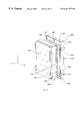
- FIGS. 5A-5E show another embodiment of a collimator exchanger according to the present invention.
- Gates 414 and 416 are attached to support column 450 by hinge joints 422 a and 422 b . Both gates 414 and 416 are coupled to a fixed gear 430 attached to post 450 .
- Gates 414 and 416 each have collimator trays 420 arranged back-to-back to allow two collimator exchanges to be performed concurrently.
- FIG. 5A gate 414 is shown in its home or closed position, and gate 416 is shown in its exchange or open position.
- FIG. 5B gates 414 and 416 are both shown in their home positions.
- gates 414 and 416 When gates 414 and 416 are both in their home positions, the exchanger maintains a thin profile that reduces the area occupied by the exchanger.
- FIG. 5C gates 414 and 416 are shown without top covers 414 a and 416 a , respectively. Detail A is shown in FIG. 5 D.
- worm gear motors 432 and 434 Housed within top covers 414 a and 416 a are worm gear motors 432 and 434 attached to arms 433 and 435 , respectively, of gates 414 and 416 , respectively.
- Worm gear motors 432 and 434 are each coupled to fixed gear 430 to independently rotate their respective gates between their home and exchange positions. As shown in FIG.
- a latch 440 extends out from a top edge of each tray 420 to prevent a collimator from falling out of tray 420 .
- Pins 428 on tabs 427 engage lower receiving holes in collimator tabs (see FIG. 4C, for example) to further secure a collimator in tray 420 .
- FIG. 6 shows yet another embodiment of a collimator exchanger according to the present invention.
- a gate 516 is coupled to a top main track 502 a and a bottom main track 502 b to allow gate 516 to slide along tracks 502 a and 502 b .
- Collimator carriers 520 are coupled to gate 516 and house collimators 518 , such as those used in conjunction with gamma ray detectors.
- Pins 506 extending from top and bottom edges of gate 516 engage guide tracks 504 a and 504 b which are hinged are one of their ends to tracks 502 a and 502 b , respectively, at fixed points.
- Guide tracks 504 a and 504 b help rotate gate 516 between its home position and its exchange position as shown in FIGS. 7A-7D.
- FIG. 7A shows gate 516 slightly offset from its home position.
- Guide track 504 a is substantially parallel to main track 502 a when gate 516 is in its home position.
- FIGS. 7B and 7C show gate 516 sliding along main track 502 a while also rotating in a direction opposite to the rotation of guide track 504 a .
- Guide track 504 a helps rotate gate 516 by guiding pin 506 as gate 516 is also sliding along main track 502 a .
- FIG. 7D gate 516 is shown in its exchange position, in which gate 516 is substantially perpendicular to main track 502 a.
- the gates have been described as rotating between their home and exchange positions. However, it is appreciated that the gates can be moved between their home and exchange positions with purely translational movement. For example, the gates could slide in and out of a slot in a wall adjacent to the gantry.
Abstract
Description
Claims (28)
Priority Applications (1)
| Application Number | Priority Date | Filing Date | Title |
|---|---|---|---|
| US09/448,567 US6441377B1 (en) | 1999-11-23 | 1999-11-23 | System for exchanging and storing collimators for medical imaging devices |
Applications Claiming Priority (1)
| Application Number | Priority Date | Filing Date | Title |
|---|---|---|---|
| US09/448,567 US6441377B1 (en) | 1999-11-23 | 1999-11-23 | System for exchanging and storing collimators for medical imaging devices |
Publications (1)
| Publication Number | Publication Date |
|---|---|
| US6441377B1 true US6441377B1 (en) | 2002-08-27 |
Family
ID=23780828
Family Applications (1)
| Application Number | Title | Priority Date | Filing Date |
|---|---|---|---|
| US09/448,567 Expired - Fee Related US6441377B1 (en) | 1999-11-23 | 1999-11-23 | System for exchanging and storing collimators for medical imaging devices |
Country Status (1)
| Country | Link |
|---|---|
| US (1) | US6441377B1 (en) |
Cited By (7)
| Publication number | Priority date | Publication date | Assignee | Title |
|---|---|---|---|---|
| US20030230723A1 (en) * | 2002-06-12 | 2003-12-18 | Koninklijke Philips Electronics N.V. | Gamma camera workflow automation |
| US20080107239A1 (en) * | 2006-11-03 | 2008-05-08 | Sohail Sayeh | Collimator changer |
| US20080224051A1 (en) * | 2007-03-14 | 2008-09-18 | Digirad Corporation | Multi-axis moveable gantry gamma camera |
| US20100193698A1 (en) * | 2005-05-16 | 2010-08-05 | Koninklijke Philips Electronics N. V. | Gantry mounted patient table and exchanger for medical imaging |
| CN103489496A (en) * | 2013-09-10 | 2014-01-01 | 沈阳东软医疗系统有限公司 | X-ray collimating device for CT machine |
| EP2716328A1 (en) * | 2012-10-08 | 2014-04-09 | ELEKTA AB (publ.) | Apparatus and methods for fitting attachments |
| CN108079444A (en) * | 2018-01-12 | 2018-05-29 | 广东东阳光药业有限公司 | Collimator changer and its application method |
Citations (4)
| Publication number | Priority date | Publication date | Assignee | Title |
|---|---|---|---|---|
| US3982133A (en) * | 1972-11-15 | 1976-09-21 | G. D. Searle & Co. | Collimator changer for scintillation camera |
| US4109155A (en) * | 1973-01-16 | 1978-08-22 | Siemens Aktiengesellschaft | Gamma camera |
| US4663531A (en) * | 1984-02-09 | 1987-05-05 | Kabushiki Kaisha Toshiba | Mechanism to mount a collimator to a radiation detector of a nuclear medicine diagnostic apparatus |
| US5519223A (en) * | 1994-03-03 | 1996-05-21 | Adac Laboratories, Inc. | Apparatus and method for automated collimator exchange |
-
1999
- 1999-11-23 US US09/448,567 patent/US6441377B1/en not_active Expired - Fee Related
Patent Citations (4)
| Publication number | Priority date | Publication date | Assignee | Title |
|---|---|---|---|---|
| US3982133A (en) * | 1972-11-15 | 1976-09-21 | G. D. Searle & Co. | Collimator changer for scintillation camera |
| US4109155A (en) * | 1973-01-16 | 1978-08-22 | Siemens Aktiengesellschaft | Gamma camera |
| US4663531A (en) * | 1984-02-09 | 1987-05-05 | Kabushiki Kaisha Toshiba | Mechanism to mount a collimator to a radiation detector of a nuclear medicine diagnostic apparatus |
| US5519223A (en) * | 1994-03-03 | 1996-05-21 | Adac Laboratories, Inc. | Apparatus and method for automated collimator exchange |
Cited By (16)
| Publication number | Priority date | Publication date | Assignee | Title |
|---|---|---|---|---|
| US6906328B2 (en) * | 2002-06-12 | 2005-06-14 | Koninklijke Philips Electronics N.V. | Gamma camera workflow automation |
| US20030230723A1 (en) * | 2002-06-12 | 2003-12-18 | Koninklijke Philips Electronics N.V. | Gamma camera workflow automation |
| US20100193698A1 (en) * | 2005-05-16 | 2010-08-05 | Koninklijke Philips Electronics N. V. | Gantry mounted patient table and exchanger for medical imaging |
| US8822934B2 (en) | 2006-11-03 | 2014-09-02 | Accuray Incorporated | Collimator changer |
| US20080107239A1 (en) * | 2006-11-03 | 2008-05-08 | Sohail Sayeh | Collimator changer |
| WO2008063303A2 (en) * | 2006-11-03 | 2008-05-29 | Accuray Incorporated | Collimator changer |
| WO2008063303A3 (en) * | 2006-11-03 | 2008-10-09 | Accuray Inc | Collimator changer |
| CN101548201B (en) * | 2006-11-03 | 2012-06-06 | 艾可瑞公司 | Collimator changer |
| US20080224051A1 (en) * | 2007-03-14 | 2008-09-18 | Digirad Corporation | Multi-axis moveable gantry gamma camera |
| US9066669B2 (en) | 2012-10-08 | 2015-06-30 | Elekta Ab (Publ) | Apparatus and methods for fitting attachments |
| EP2716328A1 (en) * | 2012-10-08 | 2014-04-09 | ELEKTA AB (publ.) | Apparatus and methods for fitting attachments |
| US20150071411A1 (en) * | 2013-09-10 | 2015-03-12 | Shenyang Neusoft Medical Systems Co., Ltd. | X-ray collimator for ct system |
| CN103489496A (en) * | 2013-09-10 | 2014-01-01 | 沈阳东软医疗系统有限公司 | X-ray collimating device for CT machine |
| US9138196B2 (en) * | 2013-09-10 | 2015-09-22 | Shenyang Neusoft Medical Systems Co., Ltd. | X-ray collimator for CT system |
| CN103489496B (en) * | 2013-09-10 | 2016-01-27 | 沈阳东软医疗系统有限公司 | A kind of CT machine X ray collimator apparatus |
| CN108079444A (en) * | 2018-01-12 | 2018-05-29 | 广东东阳光药业有限公司 | Collimator changer and its application method |
Similar Documents
| Publication | Publication Date | Title |
|---|---|---|
| CN111207282B (en) | Method and system for pivotable tablet computer stand | |
| JP2559828B2 (en) | Connection structure of system components | |
| JP5517855B2 (en) | X-ray equipment | |
| EP0499253B1 (en) | Scintillation camera | |
| US4645933A (en) | Emissive computed tomography | |
| US20190125284A1 (en) | Radiological imaging device with improved maneuverability | |
| EP0194728B1 (en) | Collimator exchanging system | |
| US6776527B1 (en) | Patient table docking system and method for tomography scanners | |
| US20180340951A1 (en) | Transport device having a tilted driving surface | |
| US20040105187A1 (en) | Magazine-Based Data Cartridge Library | |
| US6441377B1 (en) | System for exchanging and storing collimators for medical imaging devices | |
| US20040264042A1 (en) | Magazine-Based Data Cartridge Library | |
| US20040264040A1 (en) | Magazine-Based Data Cartridge Library | |
| US20040264037A1 (en) | Magazine-Based Data Cartridge Library | |
| US5519223A (en) | Apparatus and method for automated collimator exchange | |
| JPH08160051A (en) | Analyzer having plurality of vertically arranged incubators | |
| US20100193698A1 (en) | Gantry mounted patient table and exchanger for medical imaging | |
| EP0391259B1 (en) | Scintillation camera | |
| IL98815A (en) | Scintillation camera gantry supporting a plurality of detector heads between two parallel plates | |
| US6590214B1 (en) | Collimator exchange system | |
| EP2643844A1 (en) | Combination computed and direct radiography system and method | |
| JP2019530484A (en) | Robot and robot assembly for patient positioning | |
| CN109157234B (en) | Collimator vehicle with mounting structure and driving control method thereof | |
| US20080224051A1 (en) | Multi-axis moveable gantry gamma camera | |
| EP1306053A2 (en) | Versatile radiography system |
Legal Events
| Date | Code | Title | Description |
|---|---|---|---|
| AS | Assignment |
Owner name: ADAC LABORATORIES, CALIFORNIA Free format text: ASSIGNMENT OF ASSIGNORS INTEREST;ASSIGNORS:HUG, PAUL;HASSAN, RIZWAN;KARMALAWY, MOATAZ;REEL/FRAME:010423/0286 Effective date: 19991122 |
|
| AS | Assignment |
Owner name: KONINKLIJKE PHILIPS ELECTRONICS N.V., NETHERLANDS Free format text: ASSIGNMENT OF ASSIGNORS INTEREST;ASSIGNOR:PHILIPS MEDICAL SYSTEMS (CLEVELAND), INC.;REEL/FRAME:013113/0189 Effective date: 20020711 |
|
| AS | Assignment |
Owner name: KONINKLIJKE PHILIPS ELECTRONICS N. V., NETHERLANDS Free format text: ASSIGNMENT OF ASSIGNORS INTEREST;ASSIGNOR:ADAC LABORATORIES, INC.;REEL/FRAME:013475/0449 Effective date: 20020923 |
|
| FPAY | Fee payment |
Year of fee payment: 4 |
|
| REMI | Maintenance fee reminder mailed | ||
| LAPS | Lapse for failure to pay maintenance fees | ||
| STCH | Information on status: patent discontinuation |
Free format text: PATENT EXPIRED DUE TO NONPAYMENT OF MAINTENANCE FEES UNDER 37 CFR 1.362 |
|
| FP | Lapsed due to failure to pay maintenance fee |
Effective date: 20100827 |