US6388543B1 - System for eight-phase 45° polyphase filter with amplitude matching - Google Patents
System for eight-phase 45° polyphase filter with amplitude matching Download PDFInfo
- Publication number
- US6388543B1 US6388543B1 US09/666,501 US66650100A US6388543B1 US 6388543 B1 US6388543 B1 US 6388543B1 US 66650100 A US66650100 A US 66650100A US 6388543 B1 US6388543 B1 US 6388543B1
- Authority
- US
- United States
- Prior art keywords
- phase
- signals
- resistors
- capacitors
- product
- Prior art date
- Legal status (The legal status is an assumption and is not a legal conclusion. Google has not performed a legal analysis and makes no representation as to the accuracy of the status listed.)
- Expired - Lifetime
Links
- 239000003990 capacitor Substances 0.000 claims description 34
- 238000000034 method Methods 0.000 claims description 14
- 238000010586 diagram Methods 0.000 description 17
- 238000013459 approach Methods 0.000 description 3
- 230000007423 decrease Effects 0.000 description 3
- 238000006243 chemical reaction Methods 0.000 description 1
- 230000000295 complement effect Effects 0.000 description 1
Images
Classifications
-
- H—ELECTRICITY
- H03—ELECTRONIC CIRCUITRY
- H03H—IMPEDANCE NETWORKS, e.g. RESONANT CIRCUITS; RESONATORS
- H03H7/00—Multiple-port networks comprising only passive electrical elements as network components
- H03H7/18—Networks for phase shifting
- H03H7/21—Networks for phase shifting providing two or more phase shifted output signals, e.g. n-phase output
Definitions
- This invention relates to polyphase filters and, more specifically, to an eight-phase 45° polyphase filter with amplitude matching.
- Certain radio receiver architectures require that signals be phase split equally into eight separate phases with constant 45° phase splits between them.
- direct conversion receivers and subharmonic frequency translators for use in such receivers may have such requirements.
- preprocessors for improving the switching characteristics of a local oscillator input to such frequency translators may also have these requirements.
- phase splits are through the use of passive RC filters, that are commonly called polyphase filters.
- passive RC filters that are commonly called polyphase filters.
- the voltage across the capacitor will lag the current, and the voltage across the resistor, by 90°.
- the two inputs are 180° out of phase with each other and four outputs are available, each of which has a phase angle difference of 90° relative to the next output.
- the phase angle of an output voltage relative to an input voltage can be achieved for a particular frequency.
- the inputs of two differential RC phase splitters can be connected.
- the resistor and capacitor values of the two phase splitters can be selected so that there is a 45° phase angle difference between an output of the first phase splitter and a corresponding output of the second phase splitter at a particular frequency.
- the result is eight outputs with 45° phase splits between them at a particular frequency.
- the four outputs that are available from a differential RC phase splitter can be amplitude matched at a particular frequency by selection of appropriate resistor and capacitor values.
- the resistor and capacitor values cannot, in general, be selected to achieve both amplitude matching and a particular phase difference relative to the input.
- a full eight-phase 45° split is achieved by tying together the inputs of two offset four-phase 90° phase splitters.
- the resistor and capacitor values are selected to obtain the 45° phase angle difference between corresponding outputs of the two offset phase splitters.
- Amplitude matching is achieved by obtaining the inputs for that stage of the polyphase filter from an additional single four-phase 90° phase splitter, whose resistor and capacitor values are selected to achieve amplitude matching.
- the additional phase splitter can distribute power evenly among the four inputs of the two offset phase splitters, so as to cancel out an uneven power distribution which otherwise would occur between the outputs of the two offset phase splitters.
- FIG. 1 is a circuit diagram of an RC series circuit with a sinusoidal voltage source.
- FIG. 2 is a phasor diagram of voltages in FIG. 1 .
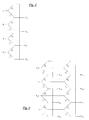
- FIG. 3 is a circuit diagram of a two-phase 90° polyphase filter.
- FIG. 4 is a circuit diagram of a four-phase 90° polyphase filter with two inputs.
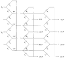
- FIG. 5 is a circuit diagram of an eight-phase 45° polyphase filter with two inputs.
- FIG. 6 is a circuit diagram of an eight-phase 45° polyphase filter with four inputs.
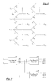
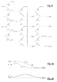
- FIG. 7 is a block diagram illustrating an example of phase-splitting to achieve an eight-phase 45° phase split with amplitude matching.
- FIG. 8 is a circuit diagram of an eight-phase 45° polyphase filter with two inputs.
- FIG. 9 a is a graph representing phase angle (between an output and an input) versus frequency.
- FIG. 9 b is a graph representing the difference between the phase angles of two outputs versus frequency.
- FIG. 1 is a circuit diagram, for discussion purposes, of a prior art RC series circuit with a sinusoidal voltage source V i (bolding indicates a phasor) driving a current I through resistor R and capacitor C.
- FIG. 2 is a phasor diagram of voltages in FIG. 1 .
- the voltage across resistor R is IR
- the voltage across capacitor C is I(1/j ⁇ C).
- V i IR+I(1/j ⁇ C).
- the voltage across R, IR always leads V i by a phase angle ⁇
- the voltage across C, I(1/j ⁇ C) always lags IR by 90°.
- the phase angle ⁇ arctan(1/ ⁇ RC).
- FIG. 3 is a circuit diagram, for discussion purposes, of a two-phase 90° polyphase filter. (“Polyphase filter” and “phase splitter” are used interchangeably.)
- Polyphase filter and “phase splitter” are used interchangeably.
- V i V i1 ⁇ V a
- V 1 and V 2 are 90° out of phase with respect to each other, regardless of the frequency, the value of R, or the value of C.
- the phase angles of V 1 and V 2 with respect to V i are ⁇ 45° and +45°, respectively.
- Each side of FIG. 3 is effectively an RC series circuit as in FIG. 1 .
- the circuit of FIG. 4 is a combination of two circuits like the circuit of FIG. 3 . Consequently, V o1 lags V o2 by 90°, and they straddle V i1 with respect to phase angle. Similarly, V o3 lags V o4 by 90°, and they straddle V i2 with respect to phase angle.
- FIG. 5 is a circuit diagram of a differential eight-phase 45° polyphase filter. It is a combination of two circuits like the circuit of FIG. 4, with the respective inputs of the two circuits connected and the respective virtual grounds of the two circuits connected. Inputs V i1 and V i2 are of equal amplitude and 180° out of phase with each other. Each of outputs V o11 , V o12 , V o13 and V o14 is 90° out of phase with the next output and, similarly, each of outputs V o21 , V o22 , V o23 and V o24 is 90° out of phase with the next output.
- the phase angle of an output voltage relative to an input voltage can be achieved for a particular frequency, by selection of the resistor and capacitor values.
- the values of R 1 C 1 and R 2 C 2 can be chosen so that V o21 , V o22 , V o23 and V o24 lead V o11 , V o12 , V o13 and V o14 , respectively, by 45° for a particular frequency (for an unloaded filter).
- the phase angles of V 011 , V o21 , V o12 , V o22 , V o13 , V o23 , V o14 and V o24 are 22.5°, 67.5°, 112.5°, 157.5°, 202.5°, 247.5°, 292.5° and 337.5°, respectively, with respect to V i1 for an unloaded filter.
- FIG. 6 is a circuit diagram similar to FIG. 5, but there are four inputs V i1 , V i2 , V i3 and V i4 .
- the intermediate points which were virtual grounds in FIG. 5 are additional voltage inputs in FIG. 6 .
- FIG. 6 In the circuit of FIG.
- V 012 V i2 ⁇ j ⁇ ⁇ ⁇ ⁇ ⁇ R 1 ⁇ C 1 1 + j ⁇ ⁇ ⁇ ⁇ R 1 ⁇ C 1 + V i3 ⁇ 1 1 + j ⁇ ⁇ ⁇ ⁇ ⁇ R 1 ⁇ C 1
- V o13 V i3 ⁇ j ⁇ ⁇ ⁇ ⁇ ⁇ R 1 ⁇ C 1 1 + j ⁇ ⁇ ⁇ ⁇ R 1 ⁇ C 1 + V i4 ⁇ 1 1 + j ⁇ ⁇ ⁇ ⁇ R 1 ⁇ C 1
- V 014 V i4 ⁇ j ⁇ ⁇ ⁇ ⁇ ⁇ R 1 ⁇ C 1 1 + j ⁇ ⁇ ⁇ ⁇ R 1 ⁇ C 1 + V i1 ⁇ 1 1 + j ⁇ ⁇ ⁇ ⁇ ⁇ R 1 ⁇ C 1 V 02
- Each output has a contribution from two inputs.
- the transfer functions applied to the two inputs have the same denominator, and the numerator of one transfer function is entirely “real” and the numerator of the other transfer function is entirely “imaginary.”
- V i2 leads V i1 by 90°
- each of those inputs will add in-phase for V o11 and each of those inputs will add in-phase for V o21 .
- each input leads the preceding input by 90°, then the two inputs to each output will add in-phase.
- each of the inputs V i1 , V i2 , V i3 and V i4 has the same amplitude
- V i2 jV i1 ,
- Each of outputs V o11 , V o12 , V o13 and V o14 will have the same amplitude, and each of outputs V o21 , V o22 , V o23 and V o24 will have the same amplitude.
- V o11 the ratio of V o11 , to V o21 is ( 1 + ⁇ ⁇ ⁇ R 1 ⁇ C 1 ) + j ⁇ ( 1 + ⁇ ⁇ ⁇ R 2 ⁇ C 2 ) ( 1 + ⁇ ⁇ ⁇ R 2 ⁇ C 2 ) + j ⁇ ( 1 + ⁇ ⁇ ⁇ R 1 ⁇ C 1 )
- each of outputs V o11 , V o12 , V o13 and V o14 will lead the previous output by 90°
- each of the inputs V i1 , V i2 , V i3 and V i4 has the same amplitude and leads the preceding input by 90°.
- R 1 ⁇ C 1 R 2 ⁇ C 2 ⁇ 5.7
- phase angles of V o11 , V o21 , V o12 , V o22 , V o13 , V o23 , V o14 and V o24 will be 22.5°, 67.5°, 112.5°, 157.5°, 202.5°, 247.5°, 292.5° and 337.5°, respectively, with respect to (V i1 ⁇ V i2 ).
- This would be the eight-phase 45° phase splitting with amplitude matching which is sought. Since (V i1 ⁇ V i2 ) (1 ⁇ j)V i1 , (V i1 ⁇ V i2 ) lags V i1 by 45°.
- FIG. 7 is a block diagram illustrating an example of phase-splitting to achieve an eight-phase 45° phase split with amplitude matching.
- Two signals V i1 and V i2 of equal amplitude and 180° out of phase with each other, can be split (12) to four intermediate signals of equal amplitude, each one of which is 90° out of phase with the next one of the four signals.
- the second input, V i2 can already be available in some embodiments and, in other embodiments, can readily be obtained by inverting V i1 as is well known in the art.
- the amplitude matching of the resulting four intermediate signals can be achieved for a particular frequency by appropriate selection of component values in a four-phase 90° polyphase filter.
- the amplitude-matched point can result in the four intermediate signals having phase angles of 45°, 135°, 225°, and 315° with respect to V i1 in FIG. 7 . This was explained regarding the circuit illustrated in FIG. 4 .
- the four intermediate signals can be converted ( 14 ) to a first group of four output signals, each one of which is 90° out of phase with the next one.
- the four intermediate signals also can be converted (16) to a second group of four output signals, each one of which is 90° out of phase with the next one.
- the first and second groups of output signals in FIG. 7 can be offset from each other, respectively, by 45°. This was explained regarding the circuit illustrated in FIG. 5 . For an unloaded filter, in one embodiment, this can be achieved for a particular frequency by appropriate selection of component values in two four-phase 90° polyphase filters with the same input signals.
- FIG. 8 is a circuit diagram of a differential eight-phase 45° polyphase filter, implementing the block diagram of FIG. 7 .
- Inputs V i1 and V i2 are of equal amplitude and 180° out of phase with each other.
- the first stage is similar to the circuit of FIG. 4 .
- ⁇ 1 R 3 ⁇ C 3 ,
- the four outputs of the first stage i.e., the intermediate signals which are inputs to the second stage
- the first stage outputs will have phase angles of 45°, 135°, 225° and 315° with respect to V i1 .
- the second stage of the circuit of FIG. 8 is similar to the circuit of FIG. 6 .
- ⁇ 1 R 3 ⁇ C 3
- R 1 ⁇ C 1 ⁇ R 2 ⁇ C 2 1 ⁇ 2
- ⁇ ⁇ R 1 ⁇ C 1 R 2 ⁇ C 2 ⁇ 5.7
- the second stage outputs will be 45° phase-split and amplitude matched. They will have phase angles of 22.5°, 67.5°, 112.5°, 157.5°, 202.5°, 247.5°, 292.5° and 337.5° with respect to V i1 .
- FIG. 9 a is an illustration representing a plot of phase angle ⁇ (between an output and an input in the circuit of FIG. 8) versus log ⁇ .
- a phase angle ⁇ arctan(1/ ⁇ RC).
- the phase angle ⁇ approaches 90° asymptotically as 1/ ⁇ RC increases and is effectively a constant 90° when ⁇ is less than about an order of magnitude less than 1/RC.
- the phase angle ⁇ approaches 0° asymptotically as 1/ ⁇ RC decreases and is effectively a constant 0° when ⁇ is more than about an order of magnitude more than 1/RC.
- FIG. 9 a is an illustration of two plots, ⁇ 1 and ⁇ 2 , representing the phase angle for two different values of RC, R 1 C 1 and R 2 C 2 , respectively.
- R 1 C 1 (K)(R 2 C 2 ) where K is a constant
- log((1/K) ⁇ ) log ⁇ +log (1/K)
- log (1/K) is a constant
- the plot representing ⁇ 1 is just a translation along the log ⁇ axis of the plot representing ⁇ 2 .
- FIG. 9 b is an illustration representing a plot of the difference in phase angle ⁇ between ⁇ 2 and ⁇ 1 in FIG. 9 a versus log ⁇ . If R 1 ⁇ C 1 R 2 ⁇ C 2 ⁇ 5.7 ,
- ⁇ 1 will be 22.5° when ⁇ 2 is 67.5°. This was explained regarding the circuit illustrated in FIG. 5 . In that case, ⁇ would peak at that point and would equal 45°. As ⁇ changes in either direction from that point, one of the two phase angles ( ⁇ 1 or ⁇ 2 ) will move closer to 45° and the other will move further away. For a given change in ⁇ , the phase angle getting closer to 45° will increase (or decrease) more than the other phase angle, and ⁇ will decrease as represented in FIG. 9 b.
- ⁇ remains relatively flat over a wide band (approximately the desired operating frequency ⁇ 50%).
- a circuit such as in FIG. 5 would have a severe amplitude mismatch at its output as a consequence of the offset nature of the two RC constants.
- the addition of the first stage, as in the example of FIG. 8 permits the eight-phase 45° split with amplitude matching. The first stage distributes power evenly among the four inputs to the second stage, cancelling out the uneven distribution which would occur otherwise in the second stage.
- circuits discussed above were analyzed in a voltage mode, but the same principles apply to current mode signals. Using current inputs and outputs would result in the same phase splitting and amplitude matching.
Abstract
Description


Claims (21)
Priority Applications (6)
| Application Number | Priority Date | Filing Date | Title |
|---|---|---|---|
| US09/666,501 US6388543B1 (en) | 2000-09-18 | 2000-09-18 | System for eight-phase 45° polyphase filter with amplitude matching |
| CNB018189881A CN100373788C (en) | 2000-09-18 | 2001-09-10 | Polyphase filter and method for signal phase seperation |
| EP01969015.5A EP1323237B1 (en) | 2000-09-18 | 2001-09-10 | System for eight-phase 45° polyphase filter with amplitude matching |
| KR1020037003894A KR100800235B1 (en) | 2000-09-18 | 2001-09-10 | System for eight-phase 45° polyphase filter with amplitude matching |
| JP2002527071A JP4740408B2 (en) | 2000-09-18 | 2001-09-10 | 8-phase 45 ° polyphase filter system with amplitude matching |
| PCT/US2001/042114 WO2002023749A1 (en) | 2000-09-18 | 2001-09-10 | System for eight-phase 45° polyphase filter with amplitude matching |
Applications Claiming Priority (1)
| Application Number | Priority Date | Filing Date | Title |
|---|---|---|---|
| US09/666,501 US6388543B1 (en) | 2000-09-18 | 2000-09-18 | System for eight-phase 45° polyphase filter with amplitude matching |
Publications (1)
| Publication Number | Publication Date |
|---|---|
| US6388543B1 true US6388543B1 (en) | 2002-05-14 |
Family
ID=24674336
Family Applications (1)
| Application Number | Title | Priority Date | Filing Date |
|---|---|---|---|
| US09/666,501 Expired - Lifetime US6388543B1 (en) | 2000-09-18 | 2000-09-18 | System for eight-phase 45° polyphase filter with amplitude matching |
Country Status (6)
| Country | Link |
|---|---|
| US (1) | US6388543B1 (en) |
| EP (1) | EP1323237B1 (en) |
| JP (1) | JP4740408B2 (en) |
| KR (1) | KR100800235B1 (en) |
| CN (1) | CN100373788C (en) |
| WO (1) | WO2002023749A1 (en) |
Cited By (11)
| Publication number | Priority date | Publication date | Assignee | Title |
|---|---|---|---|---|
| US20050141165A1 (en) * | 2002-04-11 | 2005-06-30 | Koninklijke Philips Electronics N.C. | Polyphase filter with integrators |
| US20050174196A1 (en) * | 2004-02-10 | 2005-08-11 | Tony Yang | Symmetrical polyphase network |
| US20050175132A1 (en) * | 2004-02-10 | 2005-08-11 | Tony Yang | Super harmonic filter and method of filtering frequency components from a signal |
| US20050175130A1 (en) * | 2004-02-10 | 2005-08-11 | Tony Yang | Current mode image rejection mixer and method thereof |
| US20060170507A1 (en) * | 2005-02-01 | 2006-08-03 | Samsung Electronics Co., Ltd. | Quadrature signal generator for tuning phases of all of four generated quadrature signals |
| US20060252396A1 (en) * | 2005-05-09 | 2006-11-09 | Dspg Ltd. | Phase generator using polyphase architecture |
| US20080012660A1 (en) * | 2006-07-12 | 2008-01-17 | Fujitsu Limited | Phase shifter circuit with proper broadband performance |
| US7332976B1 (en) * | 2005-02-04 | 2008-02-19 | Cypress Semiconductor Corporation | Poly-phase frequency synthesis oscillator |
| US20100178890A1 (en) * | 2007-03-29 | 2010-07-15 | Panasonic Corporation | Receiving device and electronic equipment using the same |
| US20110092169A1 (en) * | 2009-10-19 | 2011-04-21 | Qualcomm Incorporated | Lr polyphase filter |
| US20120274415A1 (en) * | 2011-04-28 | 2012-11-01 | Toyon Research Corporation | Wide bandwidth integrated 2x4 rf divider |
Families Citing this family (3)
| Publication number | Priority date | Publication date | Assignee | Title |
|---|---|---|---|---|
| JP4818809B2 (en) * | 2006-05-22 | 2011-11-16 | 三菱電機株式会社 | Polyphase filter circuit, image rejection mixer, and quadrature modulator |
| JP4836868B2 (en) * | 2007-05-29 | 2011-12-14 | 三菱電機株式会社 | Microwave phase shifter, image rejection mixer and quadrature modulator |
| US10119285B2 (en) | 2017-01-20 | 2018-11-06 | The Wave Pool Company, LLC | Systems and methods for generating waves |
Citations (10)
| Publication number | Priority date | Publication date | Assignee | Title |
|---|---|---|---|---|
| US3559042A (en) * | 1968-06-07 | 1971-01-26 | Int Standard Electric Corp | Polyphase symmetrical network |
| US3618133A (en) * | 1968-06-07 | 1971-11-02 | Int Standard Electric Corp | Symmetrical polyphase networks utilizing constant reactances |
| US4123712A (en) * | 1977-04-22 | 1978-10-31 | Northern Telecom Limited | Symmetrical polyphase network |
| US4326109A (en) * | 1980-04-11 | 1982-04-20 | Northern Telecom Limited | Apparatus for coupling a two-way transmission path to a one-way transmitting path and a one-way receiving path |
| US4647843A (en) * | 1984-02-16 | 1987-03-03 | Northern Telecom Limited | Trimming resistances in symmetrical polyphase networks |
| US4893035A (en) * | 1988-07-18 | 1990-01-09 | Hittite Microwave Corporation | Cascaded low pass/high pass filter phase shifter system |
| US5084686A (en) | 1989-12-29 | 1992-01-28 | Samsung Electronics Co., Ltd. | Phase splitter |
| US5608796A (en) | 1995-02-10 | 1997-03-04 | Lucent Technologies Inc. | Balanced phase splitting circuit |
| US5715529A (en) | 1992-06-26 | 1998-02-03 | U.S. Philips Corporation | FM receiver including a phase-quadrature polyphase if filter |
| US6031739A (en) | 1998-08-12 | 2000-02-29 | Lucent Technologies Inc. | Two-stage, three-phase split boost converter with reduced total harmonic distortion |
Family Cites Families (7)
| Publication number | Priority date | Publication date | Assignee | Title |
|---|---|---|---|---|
| US3530365A (en) * | 1967-09-27 | 1970-09-22 | James A Peugh | Phase shifting network for producing a phase of any value from 0 to 360 |
| DE3105436A1 (en) * | 1981-02-14 | 1982-10-07 | Robert Bosch Gmbh, 7000 Stuttgart | Circuit for splitting the signal of a PAL chrominance signal |
| JPH05191129A (en) * | 1992-01-13 | 1993-07-30 | Nippon Telegr & Teleph Corp <Ntt> | Tilt beam antenna |
| JP3181124B2 (en) * | 1992-12-28 | 2001-07-03 | 株式会社エヌ・ティ・ティ・ドコモ | Directional antenna |
| JP2729150B2 (en) * | 1994-08-19 | 1998-03-18 | 日本電気航空宇宙システム株式会社 | Polyphase circuit type phase shifter |
| JPH11298293A (en) * | 1998-04-16 | 1999-10-29 | Asahi Chem Ind Co Ltd | Phase shift circuit |
| JP3314726B2 (en) * | 1998-07-17 | 2002-08-12 | 日本電気株式会社 | Phase shift circuit, phase shift circuit using the same, oscillation circuit, and image rejection mixer |
-
2000
- 2000-09-18 US US09/666,501 patent/US6388543B1/en not_active Expired - Lifetime
-
2001
- 2001-09-10 JP JP2002527071A patent/JP4740408B2/en not_active Expired - Lifetime
- 2001-09-10 EP EP01969015.5A patent/EP1323237B1/en not_active Expired - Lifetime
- 2001-09-10 CN CNB018189881A patent/CN100373788C/en not_active Expired - Lifetime
- 2001-09-10 KR KR1020037003894A patent/KR100800235B1/en active IP Right Grant
- 2001-09-10 WO PCT/US2001/042114 patent/WO2002023749A1/en active Application Filing
Patent Citations (10)
| Publication number | Priority date | Publication date | Assignee | Title |
|---|---|---|---|---|
| US3559042A (en) * | 1968-06-07 | 1971-01-26 | Int Standard Electric Corp | Polyphase symmetrical network |
| US3618133A (en) * | 1968-06-07 | 1971-11-02 | Int Standard Electric Corp | Symmetrical polyphase networks utilizing constant reactances |
| US4123712A (en) * | 1977-04-22 | 1978-10-31 | Northern Telecom Limited | Symmetrical polyphase network |
| US4326109A (en) * | 1980-04-11 | 1982-04-20 | Northern Telecom Limited | Apparatus for coupling a two-way transmission path to a one-way transmitting path and a one-way receiving path |
| US4647843A (en) * | 1984-02-16 | 1987-03-03 | Northern Telecom Limited | Trimming resistances in symmetrical polyphase networks |
| US4893035A (en) * | 1988-07-18 | 1990-01-09 | Hittite Microwave Corporation | Cascaded low pass/high pass filter phase shifter system |
| US5084686A (en) | 1989-12-29 | 1992-01-28 | Samsung Electronics Co., Ltd. | Phase splitter |
| US5715529A (en) | 1992-06-26 | 1998-02-03 | U.S. Philips Corporation | FM receiver including a phase-quadrature polyphase if filter |
| US5608796A (en) | 1995-02-10 | 1997-03-04 | Lucent Technologies Inc. | Balanced phase splitting circuit |
| US6031739A (en) | 1998-08-12 | 2000-02-29 | Lucent Technologies Inc. | Two-stage, three-phase split boost converter with reduced total harmonic distortion |
Cited By (19)
| Publication number | Priority date | Publication date | Assignee | Title |
|---|---|---|---|---|
| US7375582B2 (en) * | 2002-04-11 | 2008-05-20 | Nxp B.V. | Polyphase filter with integrators |
| US20050141165A1 (en) * | 2002-04-11 | 2005-06-30 | Koninklijke Philips Electronics N.C. | Polyphase filter with integrators |
| US20050174196A1 (en) * | 2004-02-10 | 2005-08-11 | Tony Yang | Symmetrical polyphase network |
| US20050175132A1 (en) * | 2004-02-10 | 2005-08-11 | Tony Yang | Super harmonic filter and method of filtering frequency components from a signal |
| US20050175130A1 (en) * | 2004-02-10 | 2005-08-11 | Tony Yang | Current mode image rejection mixer and method thereof |
| US7078986B2 (en) * | 2004-02-10 | 2006-07-18 | Wionics Research | Symmetrical polyphase network |
| US7558351B2 (en) | 2004-02-10 | 2009-07-07 | Wionics Research | Super harmonic filter and method of filtering frequency components from a signal |
| US20060170507A1 (en) * | 2005-02-01 | 2006-08-03 | Samsung Electronics Co., Ltd. | Quadrature signal generator for tuning phases of all of four generated quadrature signals |
| US7397317B2 (en) * | 2005-02-01 | 2008-07-08 | Samsung Electronics Co., Ltd. | Quadrature signal generator for tuning phases of all of four generated quadrature signals |
| US7332976B1 (en) * | 2005-02-04 | 2008-02-19 | Cypress Semiconductor Corporation | Poly-phase frequency synthesis oscillator |
| US20060252396A1 (en) * | 2005-05-09 | 2006-11-09 | Dspg Ltd. | Phase generator using polyphase architecture |
| US20080012660A1 (en) * | 2006-07-12 | 2008-01-17 | Fujitsu Limited | Phase shifter circuit with proper broadband performance |
| US7633358B2 (en) * | 2006-07-12 | 2009-12-15 | Fujitsu Limited | Phase shifter circuit with proper broadband performance |
| US20100178890A1 (en) * | 2007-03-29 | 2010-07-15 | Panasonic Corporation | Receiving device and electronic equipment using the same |
| US8244197B2 (en) * | 2007-03-29 | 2012-08-14 | Panasonic Corporation | Receiving device and electronic equipment using the same |
| US20110092169A1 (en) * | 2009-10-19 | 2011-04-21 | Qualcomm Incorporated | Lr polyphase filter |
| US8412141B2 (en) | 2009-10-19 | 2013-04-02 | Qualcomm Incorporated | LR polyphase filter |
| US20120274415A1 (en) * | 2011-04-28 | 2012-11-01 | Toyon Research Corporation | Wide bandwidth integrated 2x4 rf divider |
| US9007143B2 (en) * | 2011-04-28 | 2015-04-14 | Toyon Research Corporation | Wide bandwidth integrated 2X4 RF divider |
Also Published As
| Publication number | Publication date |
|---|---|
| CN100373788C (en) | 2008-03-05 |
| JP2004524716A (en) | 2004-08-12 |
| EP1323237B1 (en) | 2018-11-14 |
| EP1323237A4 (en) | 2004-12-22 |
| KR20040005821A (en) | 2004-01-16 |
| JP4740408B2 (en) | 2011-08-03 |
| WO2002023749A1 (en) | 2002-03-21 |
| CN1475050A (en) | 2004-02-11 |
| EP1323237A1 (en) | 2003-07-02 |
| KR100800235B1 (en) | 2008-02-01 |
Similar Documents
| Publication | Publication Date | Title |
|---|---|---|
| US6388543B1 (en) | System for eight-phase 45° polyphase filter with amplitude matching | |
| RU2115222C1 (en) | Phase-angle corrector for power amplifier feedback circuit (options) | |
| US3681697A (en) | Wideband image terminated mixer | |
| US4908532A (en) | Quadrature signals generator | |
| EP1236285B1 (en) | Receiver circuit | |
| JPH0856117A (en) | Integrated microwave tuning detector | |
| US2984799A (en) | Broadband-phase r.-c. network | |
| US6321076B1 (en) | 90° phase shifter and image rejection mixer | |
| US20010013807A1 (en) | Polyphase filter | |
| JPS5855696B2 (en) | AM/FM frequency discriminator | |
| US3943467A (en) | Amplitude limiter circuit | |
| RU2127949C1 (en) | Normalization circuit to prevent divergence of normalizing voltage in communication network used for separation mode in digital system of superhigh-frequency range | |
| EP1423910A2 (en) | Receiver | |
| US2755378A (en) | Stabilized discriminator | |
| US6388605B1 (en) | Circuit for generating and/or detecting a radar signal | |
| EP1064720B1 (en) | Demodulator circuits | |
| US10566929B2 (en) | Triple-push type voltage-controlled oscillator | |
| JPS6231857B2 (en) | ||
| GB863585A (en) | Improvements in or relating to tunable discriminator circuits | |
| JPH0244402B2 (en) | FFVHENKANKAIRO | |
| RU2568389C1 (en) | Method of amplification and demodulation of frequency-modulated signals and device for its implementation | |
| JPS61296802A (en) | Fm demodulation circuit | |
| EP0957573A1 (en) | Five-port junction device | |
| JPH0590841A (en) | Modulator | |
| SU708494A1 (en) | Sensor of active components of resistance and cunductivity |
Legal Events
| Date | Code | Title | Description |
|---|---|---|---|
| AS | Assignment |
Owner name: CONEXANT SYSTEMS, INC., CALIFORNIA Free format text: ASSIGNMENT OF ASSIGNORS INTEREST;ASSIGNORS:MOLNAR, ALYOSHA C.;MAGOON, RAHUL;REEL/FRAME:011112/0401;SIGNING DATES FROM 20000911 TO 20000912 |
|
| STCF | Information on status: patent grant |
Free format text: PATENTED CASE |
|
| AS | Assignment |
Owner name: CONEXANT SYSTEMS, INC., CALIFORNIA Free format text: SECURITY INTEREST;ASSIGNOR:ALPHA INDUSTRIES, INC.;REEL/FRAME:013240/0860 Effective date: 20020625 |
|
| CC | Certificate of correction | ||
| AS | Assignment |
Owner name: WASHINGTON SUB, INC., CALIFORNIA Free format text: ASSIGNMENT OF ASSIGNORS INTEREST;ASSIGNOR:CONEXANT SYSTEMS, INC.;REEL/FRAME:013634/0157 Effective date: 20020625 |
|
| AS | Assignment |
Owner name: ALPHA INDUSTRIES, INC., MASSACHUSETTS Free format text: MERGER;ASSIGNOR:WASHINGTON SUB, INC.;REEL/FRAME:013645/0570 Effective date: 20020625 |
|
| AS | Assignment |
Owner name: SKYWORKS SOLUTIONS, INC., CALIFORNIA Free format text: MERGER;ASSIGNOR:ALPHA INDUSTRIES, INC.;REEL/FRAME:013645/0599 Effective date: 20020625 |
|
| AS | Assignment |
Owner name: ALPHA INDUSTRIES, INC., MASSACHUSETTS Free format text: RELEASE AND RECONVEYANCE/SECURITY INTEREST;ASSIGNOR:CONEXANT SYSTEMS, INC.;REEL/FRAME:014580/0880 Effective date: 20030307 |
|
| FPAY | Fee payment |
Year of fee payment: 4 |
|
| FEPP | Fee payment procedure |
Free format text: PAYER NUMBER DE-ASSIGNED (ORIGINAL EVENT CODE: RMPN); ENTITY STATUS OF PATENT OWNER: LARGE ENTITY Free format text: PAYOR NUMBER ASSIGNED (ORIGINAL EVENT CODE: ASPN); ENTITY STATUS OF PATENT OWNER: LARGE ENTITY |
|
| FPAY | Fee payment |
Year of fee payment: 8 |
|
| FPAY | Fee payment |
Year of fee payment: 12 |