US6374266B1 - Method and apparatus for storing information in a data processing system - Google Patents
Method and apparatus for storing information in a data processing system Download PDFInfo
- Publication number
- US6374266B1 US6374266B1 US09/360,852 US36085299A US6374266B1 US 6374266 B1 US6374266 B1 US 6374266B1 US 36085299 A US36085299 A US 36085299A US 6374266 B1 US6374266 B1 US 6374266B1
- Authority
- US
- United States
- Prior art keywords
- data
- repository
- unit
- hash value
- suspense
- Prior art date
- Legal status (The legal status is an assumption and is not a legal conclusion. Google has not performed a legal analysis and makes no representation as to the accuracy of the status listed.)
- Expired - Lifetime
Links
- 238000000034 method Methods 0.000 title claims abstract description 186
- 238000012545 processing Methods 0.000 title claims description 19
- 238000013479 data entry Methods 0.000 claims abstract description 3
- 230000007246 mechanism Effects 0.000 claims description 53
- 239000000872 buffer Substances 0.000 claims description 47
- 238000011010 flushing procedure Methods 0.000 claims description 39
- 238000013144 data compression Methods 0.000 claims description 34
- 230000008569 process Effects 0.000 description 40
- 238000007906 compression Methods 0.000 description 38
- 230000006835 compression Effects 0.000 description 38
- 238000007726 management method Methods 0.000 description 20
- 230000006870 function Effects 0.000 description 18
- 238000010586 diagram Methods 0.000 description 15
- 230000008520 organization Effects 0.000 description 14
- 238000011989 factory acceptance test Methods 0.000 description 10
- 238000012949 factory acceptance testing Methods 0.000 description 10
- 239000003925 fat Substances 0.000 description 10
- 238000013468 resource allocation Methods 0.000 description 9
- 238000012986 modification Methods 0.000 description 8
- 230000004048 modification Effects 0.000 description 8
- 230000008901 benefit Effects 0.000 description 7
- 238000003780 insertion Methods 0.000 description 5
- 230000037431 insertion Effects 0.000 description 5
- 238000013507 mapping Methods 0.000 description 4
- 238000005457 optimization Methods 0.000 description 4
- 238000013519 translation Methods 0.000 description 4
- 230000003466 anti-cipated effect Effects 0.000 description 3
- 238000013500 data storage Methods 0.000 description 3
- 230000001419 dependent effect Effects 0.000 description 3
- 230000006872 improvement Effects 0.000 description 3
- 238000012423 maintenance Methods 0.000 description 3
- 230000003287 optical effect Effects 0.000 description 3
- 101000880310 Homo sapiens SH3 and cysteine-rich domain-containing protein Proteins 0.000 description 2
- 102100037646 SH3 and cysteine-rich domain-containing protein Human genes 0.000 description 2
- 230000006978 adaptation Effects 0.000 description 2
- 238000006243 chemical reaction Methods 0.000 description 2
- 230000008030 elimination Effects 0.000 description 2
- 238000003379 elimination reaction Methods 0.000 description 2
- 239000012464 large buffer Substances 0.000 description 2
- 239000000203 mixture Substances 0.000 description 2
- 238000003491 array Methods 0.000 description 1
- 230000015556 catabolic process Effects 0.000 description 1
- 230000008859 change Effects 0.000 description 1
- 238000004891 communication Methods 0.000 description 1
- 238000007796 conventional method Methods 0.000 description 1
- 230000001186 cumulative effect Effects 0.000 description 1
- 230000006837 decompression Effects 0.000 description 1
- 230000007423 decrease Effects 0.000 description 1
- 230000002950 deficient Effects 0.000 description 1
- 238000006731 degradation reaction Methods 0.000 description 1
- 238000013461 design Methods 0.000 description 1
- 230000000694 effects Effects 0.000 description 1
- 238000009434 installation Methods 0.000 description 1
- 238000005192 partition Methods 0.000 description 1
- 230000000737 periodic effect Effects 0.000 description 1
- 238000011084 recovery Methods 0.000 description 1
- 230000008929 regeneration Effects 0.000 description 1
- 238000011069 regeneration method Methods 0.000 description 1
- 230000008439 repair process Effects 0.000 description 1
- 230000000717 retained effect Effects 0.000 description 1
- 230000002441 reversible effect Effects 0.000 description 1
- 238000012552 review Methods 0.000 description 1
Images


Classifications
-
- G—PHYSICS
- G06—COMPUTING; CALCULATING OR COUNTING
- G06F—ELECTRIC DIGITAL DATA PROCESSING
- G06F11/00—Error detection; Error correction; Monitoring
- G06F11/07—Responding to the occurrence of a fault, e.g. fault tolerance
- G06F11/14—Error detection or correction of the data by redundancy in operation
- G06F11/1402—Saving, restoring, recovering or retrying
- G06F11/1446—Point-in-time backing up or restoration of persistent data
- G06F11/1448—Management of the data involved in backup or backup restore
- G06F11/1453—Management of the data involved in backup or backup restore using de-duplication of the data
-
- G—PHYSICS
- G06—COMPUTING; CALCULATING OR COUNTING
- G06F—ELECTRIC DIGITAL DATA PROCESSING
- G06F16/00—Information retrieval; Database structures therefor; File system structures therefor
- G06F16/10—File systems; File servers
- G06F16/17—Details of further file system functions
- G06F16/174—Redundancy elimination performed by the file system
- G06F16/1748—De-duplication implemented within the file system, e.g. based on file segments
-
- Y—GENERAL TAGGING OF NEW TECHNOLOGICAL DEVELOPMENTS; GENERAL TAGGING OF CROSS-SECTIONAL TECHNOLOGIES SPANNING OVER SEVERAL SECTIONS OF THE IPC; TECHNICAL SUBJECTS COVERED BY FORMER USPC CROSS-REFERENCE ART COLLECTIONS [XRACs] AND DIGESTS
- Y10—TECHNICAL SUBJECTS COVERED BY FORMER USPC
- Y10S—TECHNICAL SUBJECTS COVERED BY FORMER USPC CROSS-REFERENCE ART COLLECTIONS [XRACs] AND DIGESTS
- Y10S707/00—Data processing: database and file management or data structures
- Y10S707/99951—File or database maintenance
- Y10S707/99952—Coherency, e.g. same view to multiple users
- Y10S707/99955—Archiving or backup
Definitions
- the present invention relates to a method for storing information in a data processing system and, in particular, to a method for compressing and storing information in a data processing system.
- a recurring problem in computer based data processing systems is the storing of information, such as data files, application programs and operating system programs, particularly as the size and number of program and data files continues to increase.
- This problem occurs in single user/single processor systems as well as in multi-user/multi-processor systems and in multi-processor networked systems and may occur, for example, in the normal operation of a system when the volume of data and programs to be stored in the system exceeds the storage capacity of the system.
- the problem occurs more commonly, however, in generating and storing “backup” or archival copies of a system's program and data files.
- the backup copies are typically stored in either a portion of the system's storage space or in a separate backup storage medium, either of which may, for practical considerations, have a storage capacity smaller than that of the system, so that the volume of information to be stored may exceed the capacity of the backup storage space.
- this problem occurs commonly in single user systems, and is even more severe in multi-user/multi-processors systems and in networked systems because of the volume of data generated by multiple users and because such systems typically contain multiple copies of application programs and operating system programs, which are frequently very large.
- the problem may be alleviated by the use of “chapterized” backup systems which make periodic copies of all data files, and often the program files, on a system such that the exact state of the system at any given time can be regenerated from the appropriate backup chapter.
- “chapterized” backup systems which make periodic copies of all data files, and often the program files, on a system such that the exact state of the system at any given time can be regenerated from the appropriate backup chapter.
- the sector copy method for making backup copies of files on disk drives merely copies the contents of a disk drive, sector by sector, into another storage medium, such as another disk drive or a tape drive. This method therefore not only does not reduce the volume of data to be stored, but, because the copying is on the basis of disk drive sectors, does not permit the stored information to be accessed and restored on the basis of files and directories.
- the prior art has therefore evolved and offered a number of “data compression” schemes for dealing with this problem by reducing the volume of the data or program files to be stored while retaining the information contained in those files.
- These schemes have generally used either of two basic classes or groups of data compression methods.
- the first group of methods which may be referred to as intra-file methods, searches within individual bodies of streams of data to eliminate or reduce redundant data within each individual file.
- the second group of methods which may be referred to as inter-file methods, searches across streams or bodies of data to eliminate or reduce redundancy between files in a system as entities, that is, to eliminate files that are duplicates of one another.
- the prior art can also be classified as including intra-file methods such as PKZIP, ARC, and LHZ, inter-file methods based on file and directory names such as TAPEDISK's TAPEDISK® system, and inter-file methods based on file content such as the STAC, Inc. REPLICA® system.
- intra-file methods such as PKZIP, ARC, and LHZ
- inter-file methods based on file and directory names such as TAPEDISK's TAPEDISK® system
- inter-file methods based on file content such as the STAC, Inc. REPLICA® system.
- the intra-file methods recognize that the form in which data is expressed in a file typically uses more information bits than are actually required to distinguish between one element of data and another, and that the data can be reduced in volume by an encoding method that reduces the proportion of unnecessary or redundant data bits.
- text is frequently expressed in ASCII or EBCDIC code, which uses character codes of a uniform size, typically seven or eight bits, to express the different characters or symbols of the text.
- ASCII or EBCDIC code which uses character codes of a uniform size, typically seven or eight bits, to express the different characters or symbols of the text.
- some text compression methods recognize that certain characters or symbols or combinations or sequences of characters of symbols occur more frequently than others, and assign shorter codes to represent more frequently occurring characters or combinations of characters and use longer codes only for rarer characters or combinations of characters.
- Intra-file methods generally make use of a so-called “dictionary”.
- the dictionary contains a mapping between a short sequence of bits and a long sequence of bits. Upon decompression, for each different short sequence of bits, the short sequence is looked up in the dictionary and the corresponding longer sequence of bits is substituted.
- Intra-file methods are widely used and are often implemented as computer system utility programs, such as PKZIP, and certain systems, such as certain versions of Microsoft Windows, have included zip-like compression programs as operating system utilities wherein a user may partition a section of a disk drive as an area to read, write and store compressed files.
- PKZIP computer system utility programs
- certain systems such as certain versions of Microsoft Windows
- zip-like compression programs as operating system utilities wherein a user may partition a section of a disk drive as an area to read, write and store compressed files.
- intra-file methods such as zip compression
- intra-file methods do not address many of the problems of data storage, and are at best only a partial solution to this problem.
- intra-file methods such as zip compression often provide little compression with files such as graphics files wherein the proportion of redundant bits is much less than in text type files.
- intra-file methods of compression inherently depend upon the internal relationships, such as redundancy, between the data elements of a file to compress or reconstruct files.
- intra-file methods generally cannot detect or reduce redundancy in the data between two or more files because the size of the dictionary becomes so large as to not be practical to use and are therefore generally limited to operating on files individually, so that these methods cannot detect and eliminate redundancy even between files that are literal duplicates of one another and cannot reduce the number of files to be stored.
- identifying duplicate copies of a given file there are two primary methods for identifying duplicate copies of a given file. The first is by examination of external designators, such as file name, version number, creation/modification date and size, and the second is by examination and comparison of the actual contents of the files. Identification of duplicate copies of files by examination of external designators, however, may not identify duplicate copies of files or may misidentify files as duplicates when, in fact, they are not. For example, a given user may rename a file to avoid confusion with another file having a similar name or to make the file easier for that user to remember, so that the file would appear externally to be different from other copies of the file, even though it is a duplicate of the other copies of the file.
- external designators such as file name, version number, creation/modification date and size
- Identification of duplicate copies of files by examination of external designators may not identify duplicate copies of files or may misidentify files as duplicates when, in fact, they are not. For example, a given user may rename a file to avoid confusion with
- certain external designators such as file modification date
- file modification date are inherently unreliable for at least certain types of files.
- a user may modify or customize a given file, often referred to as “patching a file”, as is provided for, for example, in certain system utility programs, and the fact of that modification or customization may not appear in the external designators examined by the file comparison utility, so that the file could appear, from its external designators, to be a copy of another file when in fact it is not.
- a user may use the MSDOS® XCOPY command to copy a directory from one disk to another. Should some program patch one of the files that has been copied, a program relying on external designators would assert that the two directories have identical contents, whereas such would not be the case.
- the file content comparison methods may be modified by performing an initial examination and comparison of the external designators, such as file name, version number, creation/modification date and size, of a new file and the previously stored files to obtain an initial determination of the probability that the new file may be a duplicate of a previously stored file.
- the external designators such as file name, version number, creation/modification date and size
- a preliminary determination of possible identity between files by examination of external indicators may result in a failure to identify duplicate copies of files, so that the duplicate files are not eliminated, or a misidentifications files as duplicates when they are not, which results in lost processing time when the contents of the files are compared.
- an operating system utility used a hash algorithm to generate a value, in this case a Cyclical Redundancy Check (CRC) algorithm, and a linker to add a header and footer to a compiled program module wherein the header contained the module name and a hash value representing module name and size and the footer contained a hash value on the entire module. Additional utilities allowed the hash values to be updated periodically. The hash values were then used when a new program module was added to a system to check whether there was already a program module having the same name and hash values, and prevented the installation of the new module if a match was found.
- CRC Cyclical Redundancy Check
- This method has not been used in inter-file compression to represent the actual contents of files for comparison of file contents, however, for a number of reasons.
- One reason is that the method is useful, for practical reasons, only with program modules or other forms of files that do not change frequently. That is, there is a high probability that the hash values representing the contents of a data file or any other form of file that changes frequently would be outdated at any given time and thus would not represent the actual contents of the file, so that a comparison with another file would be invalid.
- This would require the regeneration of the hash values each time a file was to be compared to other files, which would slow the operation of the backup/archiving system to an impractical extent, particularly for large files.
- file backup and archiving systems frequently have yet another related limitation that can become a significant problem, particularly as file sizes become ever larger and especially in multi-user/multi-processor systems where large volumes of data must be stored in a backup or archive facility. That is, file backup and archiving systems store files as files, using either their own file structures and utilities or the file structures of the system in which they operate, and typically store each backup of a system's files as, or in, a single file. File management systems, however, typically impose a limit on the maximum size of files, especially in “disaster recovery”environments, and this size may be exceeded by the cumulative volume of the files to be backed up in a single backup operation. This, in turn, may require that a backup be performed as multiple partial backups, with increased administrative and processing burdens and decreases in the overall efficiency of whatever file compression method are being used as file compression methods generally cannot be effectively applied across backup operations.
- the JARTM product by ARJ Software, Inc., is a command line archiver similar to PKZIP®, but provides delta compression of files by performing chapter archiving according to specified file lifespans.
- JARTM begins with an archival copy of the files in a file system, for example, a directory, and thereafter adds “chapters” containing copies of only those files or portions of files that may have changed since the last archival copy.
- this method not being based on clusters or the contents of the actual clusters, cannot duplicate the organization of data on disks, which is in sectors/clusters, and may err by duplicating unchanged files or by not duplicating changed files as the archiving decision is based on the names and attributes of files, such as file name, file modification date, and so forth, rather than on the contents of the files and changes therein.
- JARTM cannot replicate the non-file data exactly. That is, JARTM has no means of accessing the on-disk data structures like directories and File Allocation Tables.
- the STAC, Inc. REPLICA® system which is described in U.S. Pat. No. 5,907,672, provides a method by which a tape drive can be used to simulate a mountable file system known to, for example, Netware or DOS. It is well known and understood that locating and reading a specific, selected body of data from a tape unit, such as to compare the previously stored data with newly received data, is a very slow process and limits the speed of operation of a tape based system severely.
- the REPLICATM system is a tape based archiving system very similar to the aforementioned TAPEDISK wherein the speed of operation of the system is increased by reducing the number of accesses to archived blocks of data on the tape.
- the system At each archiving operation the system generates a checksum for each block of data, such as a cluster or allocation unit, read from a data source and compares the new checksum with a stored checksum generated for the block of data from the same location in the data source in the previous archiving operation. If the checksums do not match, the data may have changed and the system reads the previously stored block of data from that location from the tape, compares it to the current block of data and writes the current block of data to tape if the data has changed.
- the method used in the REPLICA® system in U.S. Pat. No. 5,907,672 thereby uses checksums only to identify whether the data at a given location in a data source has changed, and not as identifiers to eliminate duplicate data across all blocks of data on the data source.
- the data compression methods of the present invention provide a solution to these and other problems of the prior art.
- the present invention is directed to a method for storing data from a data source in a storage device of a data repository in a computer system that includes at least one data source wherein data is stored in source allocation units.
- the method is performed by reading all source allocation units, which may be clusters or sectors of a storage device, restructuring the data into data units having a size corresponding to the repository allocation units, and generating a hash value for the data of each data unit read from the data source.
- a data table is searched for a table entry having a hash value matching a hash value of the data unit read from the data source wherein each table entry contains the hash value of a data unit stored in a repository allocation unit and a repository allocation unit pointer to the corresponding repository allocation unit.
- the data of the data unit is written into a newly allocated repository allocation unit, and generates a new table entry containing the hash value of the data unit and a repository allocation unit pointer to the newly allocated repository allocation unit is generated and written to the data table.
- the table entry having a matching hash value is accessed and the repository allocation unit pointer therein is used to read the data of the corresponding repository allocation unit and the data of the corresponding repository allocation unit are compared to the data unit.
- the data unit is discarded and, if the data of the data unit does not match the data of the corresponding repository allocation unit, the data of the data unit is written into a newly allocated repository allocation unit and a new table entry containing the hash value of the data unit and a repository allocation unit pointer to the newly allocated repository allocation unit is generated and inserted into the data table.
- the incoming data unit may have two identifiers, the data content and the sector/cluster number that will be assigned to this incoming data unit.
- the sector/cluster number is not discarded but is stored externally in some table and this table is external to the method herein described. For instance, in the TAPEDISK® software, a similar table is called the “Cluster Relocation Table.”
- the data table is partitioned into data records wherein each data record contains an array of table entries containing at least one table entry.
- the step of searching a data table for a table entry having a hash value matching that of a new data unit includes the steps of fetching a first/next data record and determining whether the fetched first/next data record is the last data record of a linked list of one or more data records in the data table wherein the last data record of the data table is not sorted according to the hash values represented therein.
- the present invention determines whether the hash value of the newly received data unit is smaller than the hash value of the first table entry of the data record and, when the hash value of the newly received data unit is smaller than the hash value of the first table entry, selects a first/next data record.
- the present invention determines whether the hash value of the newly received data unit is larger than the hash value of the last table entry of the data record and, when the hash value of the newly received data unit is larger than the hash value of the last table entry of the data record, again selects a first/next data record.
- the present invention performs a binary search to find a match between the hash value of the newly received data unit and the hash value of a table entry in the data record, and when a match is not found, adds a new entry to the data table or, when a match is found, discards the new data unit.
- the present invention performs a linear search to find a match between the hash value of the newly received data unit and the hash value of a table entry in the data record.
- a match between the hash value of the newly received data unit and the hash value of a table entry in the data record is not found, a new entry to the data table is created and entered and, when a match is found, the new data unit is discarded.
- the step of inserting a new table entry into the data table includes the steps of determining whether a data record exists to receive the table entry of the newly received data unit and, if a data record does not exist to receive the table entry, creating a new data record to receive the table entry of the newly received data unit. If a data record exists to receive the table entry, the present invention determines whether the data record has space to receive a new table entry and, if the data record has space to receive a new table entry, inserts the new table entry into the last data record of the data table.
- the present invention sorts the last data record according to the hash values of the record entries appearing therein, creates a new data record to be a new last data record of the data table, and links the new last data record to the chain of one or more data records of the data table;
- the present invention determines whether there is sufficient room in a suspense array to insert a new suspense element wherein the suspense array includes one or more suspense elements and a suspense element contains the data of a new data unit having a hash value that matches the hash value of a table entry residing in the data table. If there is room in the suspense array to insert a new suspense element, the present invention inserts the new suspense element into the suspense array.
- the present invention flushes the suspense buffer by reading each suspense element of the suspense array and, for each suspense element, accesses the table entry having a matching hash value and uses the repository allocation unit pointer therein to read the data of the corresponding repository allocation unit.
- the data of the data unit represented by the suspense element and the data of the corresponding repository allocation unit are compared and if the data of the suspense element matches the data of the corresponding repository allocation unit, the data unit is discarded.
- the data of the suspense element does not match the data of the corresponding repository allocation unit, the data of the data unit is written into a newly allocated repository allocation unit, and a new table entry containing the hash value of the data unit and a repository allocation unit pointer to the newly allocated repository allocation unit is generated and inserted into the data table.
- the method for flushing the suspense array includes the steps of sorting the suspense array by the repository allocation unit pointers to the repository allocation units of the suspense elements in the suspense buffer, allocating a flushing buffer to store at least one of the suspense elements stored in the suspense array, setting a suspense array index pointer to point to the first sorted suspense element, reading suspense elements from the repository into the flushing buffer, starting with the suspense element indicated by the suspense array index pointer, and processing each allocation unit corresponding to each suspense element in the flushing buffer.
- each allocation unit corresponding to a suspense element includes the steps of comparing the data of the data unit represented by a suspense element and the data of the corresponding repository allocation unit and, if the data of the suspense element matches the data of the corresponding repository allocation unit, discarding the data unit. If the data of the suspense element does not match the data of the corresponding repository allocation unit, the data of the data unit is written into a newly allocated repository allocation unit and a new table entry containing the hash value of the data unit and a repository allocation unit pointer to the newly allocated repository allocation unit is generated and inserted into the data table.
- the suspense array index pointer is advanced to the next suspense array entry representing a suspense element in the suspense buffer that has not been processed, and this process is repeated until there are no more suspense elements in the flushing buffer to be processed.
- the method for determining whether the data of a suspense element matches the data of a data unit already represented in a table entry of a data table and residing in a repository allocation unit includes comparing the contents of a data unit represented in a suspense element with the contents of a data unit already residing in a repository allocation unit and represented in a table entry of a data table. If the contents of the data unit in the suspense element match the contents of the data unit already residing in a repository allocation unit and represented in a table entry, the data unit in the suspense element is discarded.
- the data of the data unit is written to a newly allocated repository allocation unit and a corresponding table entry containing the hash value of the data unit and a repository allocation unit pointer to the location of the data unit in the newly allocated repository allocation unit is added to the data table.
- the present invention may be embodied as a data compression mechanism for storing data from a data source in the storage device of a data repository in compressed form by eliminating duplicate clusters of the data source.
- the data compression mechanism includes a restructuring mechanism for reading data from the source allocation units and restructuring the data into data units having a size corresponding to the repository allocation units, a hash generator for generating a hash value for the data of each data unit read from the data source, and a table search mechanism responsive to each new data unit read from the data source for searching a data table for a data record having a record entry having a hash value matching a hash value of the data unit read from the data source.
- the data table includes at least one data record and each data record contains the hash value of a data unit stored in a repository allocation unit and a repository allocation unit pointer to the corresponding repository allocation unit.
- a storage manager is responsive to operation of the table search mechanism for writing a newly received data unit into a newly allocated repository allocation unit when the hash value of the newly received data unit does not match a hash value of a record entry in a data record, and a table generator responsive to operation of the table search mechanism for generating a new record entry containing the hash value of the newly received data unit and a repository allocation unit pointer to the newly allocated repository allocation unit and writing the new record entry into a data record.
- the data compression mechanism also includes a suspense processor responsive to operation of the table search mechanism for writing the data of the newly received data unit and the corresponding hash value into a suspense element of a suspense buffer when the hash value of a newly received data unit matches the hash value of a record entry in a data record.
- the suspense processor accesses the record entry having a matching hash value and using the repository allocation unit pointer therein to read the data of the corresponding repository allocation unit and compares the data of the data unit and the data of the corresponding repository allocation.
- the suspense processor discards the data unit, and if the data of the data unit does not match the data of the corresponding repository allocation unit, the suspense processor indicates the mismatch to the storage manager and the table generator.
- the storage manager is responsive to the suspense processor for writing the data of the data unit into a newly allocated repository allocation unit
- the table generator is responsive to the suspense processor for generating a new record entry containing the hash value of the data unit and a repository allocation unit pointer to the newly allocated repository allocation unit and writes the new record entry into a data record.
- the present invention may also be implemented in a mass storage device for storing data unit received from at least one data source and including a storage element for storing the data and a controller for controlling the storing of data in storage allocation units of the storage element, again operating as a data compression mechanism for storing the data in compressed form by eliminating the storing of duplicate data units.
- the mass storage device includes a hash generator for generating a hash value for the data of each data unit received by the mass storage device and a table search mechanism responsive to each new data unit for searching a data table for a table entry having a hash value matching the hash value of the new data unit wherein each table entry contains the hash value of a data unit stored in the storage element and an indicator of the storage allocation unit containing the data unit.
- a storage manager of the mass storage device is responsive to operation of the table search mechanism for writing a newly received data unit into a newly allocated storage allocation unit of the storage element when the hash value of the newly received data unit does not match a hash value of a table entry, and discarding the newly received data unit when the hash value of the newly received data unit matches a hash value of a table entry.
- the mass storage device also includes a table generator responsive to operation of the table search mechanism when the hash value of the newly received data unit does not match a hash value of a table entry for generating a new table entry containing the hash value of the newly received data unit and an indicator of the newly allocated storage allocation unit containing the newly received data unit and writing the new record entry into the data table.
- the mass storage device may also include a suspense processor responsive to operation of the table search mechanism for writing the data of the newly received data unit and the corresponding hash value into a suspense element of a suspense buffer when the hash value of a newly received data unit matches the hash value of a table entry.
- the suspense processor processes each suspense element by accessing the table entry having a matching hash value and using indicator of the storage allocation unit containing the data unit therein to read the data of the corresponding repository allocation unit and comparing the data of the data unit and the data of the corresponding repository allocation.
- the storage manager is then responsive to the suspense processor for writing the data of the data unit into a newly allocated repository allocation unit
- the table generator is responsive to the suspense processor for generating a new record entry containing the hash value of the data unit and an indicator of the newly allocated storage allocation unit containing the data unit and writing the new table entry into the data table.
- the method of the present invention also includes the method for reading, recovering, or restoring data from a data repository by mounting the contents of the repository allocation units of a data repository into a system as a restored disk volume having a directory structure identical to that of the data source and accessing files on the restored disk volume from a software application using file system input/output calls.
- the mass storage device is a disk drive includes at least one magnetic disk storage element and the repository allocation units are sectors of the magnetic disk storage element.
- the hash generator and table lookup mechanisms are embodied by associative array hardware.
- the repository allocation units are organized into one or more containers wherein each container is organized into one or more compartments and each compartment includes one or more repository allocation unit.
- the embodiment may also include a compartment set file associated with a container wherein the compartment set file contains a list of compartments that are to be treated as a single file.
- a repository allocation unit pointer is a byte offset of the location of a repository allocation unit from the beginning of the repository allocation units in the storage device of the data repository.
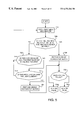
- FIG. 1 is a block diagram of a system incorporating the present invention
- FIG. 2 is a diagrammatic representation of the file structures and mechanisms of the system
- FIG. 3 is a block diagram of a system incorporating the present invention.
- FIG. 4 is a flow diagram illustrating the operation of the present invention.
- FIG. 5 is a flow diagram illustrating a search of a data compression table of the present invention.
- FIG. 6 is a flow diagram illustrating the addition of an entry to a data compression table of the present invention.
- FIG. 7 is a diagrammatic representation of a suspense array of the present invention.
- FIG. 8 is a flow diagram of the insertion of a suspense element into a suspense array of the present invention.
- FIG. 9 is a flow diagram of the flushing of a suspense array of the present invention.
- FIG. 10 is a flow diagram of the selection of suspense elements of a suspense array of the present invention.
- FIG. 11 is a flow diagram of the process for determining whether a suspense element matches an allocation unit stored in the data repository of the present invention.
- FIG. 1 A. Introduction (FIG. 1)
- System 10 may include a plurality of User Systems 12 interconnected by Network 14 wherein two of User Systems 12 , designated as User Systems 12 S and 12 R, are represented in additional detail to illustrate the present invention.
- User System 12 S represents a Data Source 16 containing data, that is, a collection of clusters and other sector-level data that likely represent data and program files, and directory information, that are to be stored in compressed form in a Data Repository 18 residing in a designated or selected User System 12 R.
- Systems 12 R and 12 S could be physically the same system.
- User System 12 R could be, for example, a so-called “Network Server”, and that the present invention is equally applicable in both peer-to-peer networks and server-based networks.
- each of User Systems 12 S and 12 R typically include a Mass Storage Unit (MSU) 20 , such as a disk drive, for storing Data 22 and Programs 24 , a Processor 26 for performing operations on Data 22 and otherwise executing operations as directed by Programs 24 , and a Memory 28 for temporarily holding Data 22 and Programs 24 currently being operated upon or executed by Processor 26 .
- MSU Mass Storage Unit
- Programs 24 will typically include a Storage Unit Driver 30 , such as a disk driver program, for controlling the reading and writing of Data 22 and Programs 24 from and to MSU 18 .
- Each User System 12 will typically include a Network Communication Device (NCD) 32 and Network Programs NPRGs) 34 for communicating with one another through Network 14 in, for example, peer-to-peer and server based networked system. It will be understood, however, that NPRGs 34 and NCDs 32 may not be required when User System 12 R and User System 12 S are the same system or node of a networked system.
- NCD Network Communication Device
- NPRGs 34 and NCDs 32 may not be required when User System 12 R and User System 12 S are the same system or node of a networked system.
- the functions and operations of the present invention are to provide a mechanism whereby Data 22 or Programs 24 or Data 22 and Programs 24 or sector-level data may be copied or read from a Data Source 16 , such as the MSU 20 of a User System 12 S and stored in compressed form in a Data Repository 18 , such as the MSU 20 of a User System 12 R.
- a Data Source 16 such as the MSU 20 of a User System 12 S
- a Data Repository 18 such as the MSU 20 of a User System 12 R.
- These functions of the present invention may be used, for example, in generating an archival or backup copy of the data and programs residing in the Data Source 16 .
- the User System 12 R containing Data Repository 18 may access and read the Data 22 and Programs 24 of a Data Source 16 using methods and devices well understood in the art, such as NCDs 32 , NPRGs 34 and Storage Unit Drivers 30 , and calls or commands to a User System 12 R through Network 14 .
- User System 12 S could write its own data into the MSU 20 of a User System 12 R, using standard network protocols.
- a User System 12 may generate compressed copies of the Data 22 and Programs 24 residing on its own MSU 20 and store the compressed copies in a Data Repository 18 comprising, for example, its own MSU 20 or another storage device, such as a second MSU 20 , a “floppy disk” drive, a CD drive or a tape drive.
- FIG. 2 therein is illustrated a general system for organizing and managing files in a system that is typical and illustrative of the great majority of file and disk management systems and that would be commonly implemented in User Systems 12 S and 12 R as illustrated in FIG. 2 .
- the two primary components of a file and disk management system are the Storage Manager 36 which controls and manages the storing of Files 38 in a MSU 20 , typically acting through a Storage Unit Driver 30 , and a File Manager 40 through which the organization of Files 38 and the storage of Files 38 are represented to a user.
- hard disk drive refers to and is used to mean a device capable of randomly accessing an arbitrary piece data.
- a “hard disk drive” could be a so-called “ram disk” or a “TAPEDISK” or any other hardware and software configuration or device that allows random access to data.
- Storage Manager 36 it is assumed in the present example that MSU 20 is a hard disk drive, or a hard disk being simulated by other software such as Stacker®, TAPEDISK®, DATMAN® or other software which acts as a hard disk emulator, which is presently the form of MSU 20 most typically found in a User System 12 .
- Storage Manager 36 organizes the storage space of MSU 20 into Allocation Units 42 which may be referred to, for example, as “clusters”, “sectors” and so on, and which may be of fixed or variable size, depending upon the particular Storage Manager 36 .
- Allocation Units 42 are referred to as “clusters” and are of fixed size while, for example, in certain “ZIP” file systems the Allocation Units 42 are of variable size.
- a difference between fixed size allocation units and variable size allocation units, for example, is that the tracking, allocation and management of allocation units is generally less complex in systems employing fixed size allocation units.
- variable size allocation units are more efficient in use of the available storage space as the size of each allocation unit is matched to the size of the data to be stored therein so that all of the storage space in each allocation is used, while unused portions of the allocation units in fixed size allocation unit systems are effectively wasted as “cluster slop”.
- Storage Manager 36 typically also creates and maintains an Allocation Table 44 , which directly or indirectly indicates which Allocation Units 42 are currently allocated to store data or are currently unallocated or are unusable for some reason, such as being located in a bad or faulty disk sector, and relates the Allocation Units 42 containing data of a given file to one another so that the data of a given file can be located.
- Microsoft DOS for example, refers to the Allocation Table 44 as a “File Allocation Table”, or FAT, and the FAT contains an Entry 46 for and corresponding to each cluster on a disk drive.
- Each Entry 46 in the Allocation Table 44 typically contains a designator indicating the current status of the corresponding cluster, such as available, allocated or unusable.
- the FAT Entry 46 corresponding to the first cluster containing data of the file contains a designator identifying the next cluster, if any, of the group of clusters allocated to store data from that file or directory. If the file or directory occupies more than one cluster, the FAT entry of each successive cluster allocated to the file or directory contains the designator of the next cluster in the group, so that all of the data of the file or directory may be located by following the chain of cluster designators.
- Yet other storage manager systems may, for example, chain the allocation units of a file internally, that is, with each allocation table entry containing an identifier of the corresponding allocation unit and an identifier of a next entry corresponding to an allocation unit containing data of the file. It will be appreciated and understood that there are many methods for organizing allocation tables and linking allocation units assigned to Ia given file or directory or other such data stream and that such methods will be well known and understood by those of ordinary skill in the relevant arts. It will also be understood that the present invention, as described in the following, may be readily adapted to use with any storage manager, and that the adaptation of the present invention will be readily understood by those or ordinary skill in the relevant arts.
- clusters may not and probably will not be allocated to files. These clusters are allocated by File Manager 40 for File Manager 40 's own use for certain “housekeeping” purposes, such as the maintenance of directories for locating files or for the allocation of space for the allocation tables themselves. For example, in the MSDOS FAT file system, space on the MSU 22 must be set aside for the Allocation Table 44 itself.
- File Manager 40 the function of File Manager 40 is to represent the organization of Files 38 and the storage of Files 3 8 to a user and to provide the user with an interface for interacting with Storage Manager 36 in storing and managing Files 38 .
- a file such as a File 38 of the present discussion, may be defined as a body or string or sequence of data comprising a program or data to be operated upon by a program, that is treated as and used as a single entity and is stored as an entity, although, as described above, this entity may physically be stored in the form of one or more allocation units.
- Files 38 are typically organized into groups of related files, according to a criteria selected by the user, a system administrator or the system, and the groups of Files 38 placed into organizational structures commonly referred to as “directories” and represented in FIG. 2 as Directories 48 . It should be noted that most file systems permit the use of a hierarchical directory organization, wherein, as illustrated in FIG. 2, a given Directory 48 may contain one or more sub-Directories 48 s and each sub-Directory 48 s may contain further sub-Directories 48 ss , and so on until the lowest level of Directory 48 contains the group of Files 38 .
- Microsoft Windows and Microsoft DOS for example, organize data into files and the files are organized in hierarchical directory structures.
- Yet other systems such as the commonly used “zip” compression utilities, organize compressed files into “archives” and, if the utility is being used in a Windows or DOS based, the archives are then treated by the Windows/DOS file manager as Files 38 .
- a “chapterized” file system in yet another form of data organization, superimposes another layer of organization on top of the hierarchical organization described above.
- a particular chapter of a file system that is, a particular collection of files at some point in time, is known by a chapter name or a chapter number.
- chapterized file systems operate at a level above the standard calls to file managers in the operating system.
- Storage Manager 36 and File Manager 40 interoperate to relate the directory and file structure constructed by a user of File Manager 40 with the physical storage of Files 38 in Allocation Units 42 on a disk drive by Storage Manager 36 .
- File Manager 40 will represent Files 38 and Directories 48 to a user by means of a displayable graphical representation of the file/directory structure wherein the Directories 48 and Files 38 are identified by names associated with the Directories 48 and Files 38 according to the naming conventions supported by the File Manager 40 .
- the functions to relate Directories 48 and the assigned file and directory names appearing therein to Allocation Units 42 are implemented in Storage Manager 36 .
- File Manager 40 may maintain information in the entries of Directories 48 that relates the assigned directory and file names as represented in Directories 48 to the corresponding Resource Allocation Units 42 and entries in Allocation Table 44 , or may store this information in a File Table 50 .
- the Storage Manager 36 will allocate Allocation Units 42 as necessary to store the data of the File 38 .
- the Storage Manager 36 will provide to the File Manager 40 an identification of the first Allocation Unit 42 allocated to store data of that file and, as described above, the chain of Allocation Units 42 may then be followed from Allocation Unit 42 to Allocation Unit 42 to access the data of that file. It should be noted that if data is subsequently added to the file, the Storage Manager 36 may subsequently follow the chain of Allocation Units 42 of the file to find the last Allocation Unit 42 of the file.
- the Storage Manager 36 after searching for unallocated Allocation Units 42 , may then allocate as many additional Allocation Units 42 as necessary to contain the added data, extending the string of Allocation Units 42 as necessary. It should be noted that in the Microsoft DOS operating system, the start of the cluster chain is stored at Microsoft defined locations in the relevant directory clusters in the same MSU 20 .
- the present invention introduces a fourth data compression method mechanism that is distinguished from the three methods of the prior art discussed above by being an inter-disk and intra-disk method based on the contents of physical and/or logical disk drives.
- the method of the present invention does not distinguish between files and non-file data, such as “directory information” and, in fact, is independent of how the data is organized on the disk.
- the present invention provides a mechanism in which any and all Allocation Units of MSU 20 can be copied or stored in such a manner that Allocation Units 42 that have identical contents are eliminated in the representation of MSU 20 in a Data Repository 18 stored on User System 12 R and a mechanism whereby data, such as Data 22 or Programs 24 , may be copied or read from a Data Source 16 , such as the MSU 20 of a User System 12 S, and stored in optionally compressed form in a Data Repository 18 .
- the implementation of the preferred embodiment of this invention understands the internal structure of the MSDOS files system, that is, the internal representation of FATs, directory structure, and at the lowest level, files, so that the preferred embodiment can determine if certain Allocation Units 42 , that is, clusters, are currently “in use” and need to be copied should the user of the present invention wish to copy the contents of the entire MSU 20 .
- the user has a choice as to whether to copy all Allocation Units 42 or just the Allocation Units 42 that the operating system, such as MSDOS, considers to be in use.
- DCM 52 A is implemented in a program residing and executing in User System 12 R and using the facilities of User System 12 R, that is, the system processor, memory, mass storage devices, and operating system, including the Storage Manager 36 and File Manager 40 to read data, e.g., clusters, data files, or programs, from a Data Source 16 and to store the data in compressed form in a Data Repository 18 .
- DCSU 52 B is implemented in a mass storage device, typically a disk drive, that may be the MSU 20 of User System 12 R or an additional mass storage device connected to the User System 12 R and dedicated to this purpose. It will be understood that other forms of mass storage device may be used for DCSU 52 B, such as a system or network disk drive array, or a tape drive or optical disk drive of a software emulator of a hard disk drive. It will also be understood that the method of the present invention may be implemented in a System 10 comprised of a single User System 10 whereupon the single User System 12 contains both the Data Source 16 and the Data Repository 18 .
- the present invention may be implemented in a System 10 comprised of multiple User Systems 12 , whereupon the Data Repository 18 will reside in a selected or assigned one of the User Systems 12 while the Data Source 16 may be comprised of one or more User Systems 12 whose files are accessible to the User System 12 in which the Data Repository 18 resides, including the User System 12 containing the Data Repository 18 .
- DCM 52 A may use the underlying operating system of the User System 12 to implement DCM 52 A and DCSU 52 B, including using the Storage Manager 36 and File Manager 40 to organize, manage and display the Repository Allocation Units (RAUs) 42 R of Data Repository 18 and files containing MDC Table 60 with MDC Records 62 and Record Entries 64 .
- RAUs Repository Allocation Units
- the File Allocation Table of operating systems such as Microsoft DOS and Microsoft Windows impose limitations on the size of files that may be handled in by the file management facilities of the operating systems. For example, a FAT 16 file system imposes a limit of 2 gigabytes on files and the FAT 32 file system imposes a limit of 4 gigabytes on the size of any particular file.
- DCM 52 A may use the file management facilities of the operating system of the system in which the present invention is implemented
- some embodiments of the invention provide an alternate mechanism for storing and managing Repository Allocation Units (RAUs) 42 R of Data Repository 18 and files containing MDC Table 60 with MDC Records 62 and Record Entries 64 that uses indirection to extend the sizes of files that can be stored and managed.
- RAUs Repository Allocation Units
- FIG. 3 it is illustrated therein that in this embodiment at least part of the storage space the system on which the invention is implemented, and in particular DCSU 52 A, is organized into one or more Containers 18 a and each Container 18 a is organized into one or more Compartments 18 b .
- a Container 18 a is thereby a collection of one or more Compartments 18 b
- each Compartment 18 b is a file comprised of one or more Repository Allocation Units 12 R that DCM 52 A uses to store all or part of, for example, the Data Units 56 of a Data Source 16 .
- a Compartment Set File 18 c that lists a set of one or more files, that is, Compartments 18 b , that are to be treated and managed, logically, as a single file.
- Each Container 18 a is treated as a single file but, through Compartment Set File 18 c , incorporates all Compartments 18 b that are listed in the Compartment Set File 18 c , so that all of the Compartments 18 b listed in a Compartment Set File 18 c are treated as a single file as an entity, that is, as the Container 18 a .
- the file mechanism further includes a Compartment Manager 18 d that functions in a manner generally analogous to the Storage Manager 36 and File Manager 40 of a conventional system to create, allocate and construct Containers 18 a , Compartments 18 b and Compartment Set Files 18 c , to allocate Repository Allocation Units 12 R to Compartments 18 b , and to write and read data to and from Repository Allocation Units 12 R.
- Container Manger 18 d also interfaces with the system native file management facilities, such as Storage Manager 36 and File Manager 40 , to translate between native system read and write operations and Container 18 a and Compartment 18 b read and write operations.
- this structure thereby uses indirection to incorporate a plurality of files, that is, Compartments 18 b , into a single file, a Container 18 a , that appears to the file management facilities as a single file.
- this structure removes the conventional FAT type limitation on file sizes, although each Container Set File 18 c can be limited as regards the size of the Container 18 a or the sizes of the Compartments 18 b therein.
- Compartments 18 b listed in Compartment Set File 18 c will automatically grow as the need for more files is encountered as data is added to the Container 18 c . It is further anticipated that the files, that is, Compartments 18 b , listed in the Compartment Set File 18 c may be spread over a multitude of User Systems 12 R. As Compartment 18 b file names are appended to a Compartment Set File 18 c , these names may be automatically generated by taking into consideration the names of other Compartment 18 b file names in the Compartment Set File 18 c.
- DCSU 52 B is implemented using Containers 18 a comprised of Compartments 18 b which in turn are listed in Compartment Set File 18 c , and a Compartment Manager 18 d as described above.
- the modifications to the above description of the present invention relating to FIG. 4 to accommodate the use of either Containers 18 a or conventional file mechanism will be apparent to those of ordinary skill in the arts after the above discussions and the following detailed descriptions of the present invention.
- the Container 18 a and Compartment 18 b file structure may be used for purposes other than the storing of Data Units 56 , such as storing the tables and records, described below, used by the present invention to perform and manage the data storage operations performed by the present invention.
- the basic data compression method performed by a DCM 52 A of the present invention comprises the following steps, certain of which will be discussed in further detail with respect to subsequent figures:
- Step 54 a Restructure Mechanism (RESTRUCT) 52 AA reads data from a Data Source 16 in Source Allocation Units (SAUs) 42 S of the Data Source 16 and, if necessary, restructures the data into Data Units 56 , each having a size corresponding to the size of Repository Allocation Units (RAUs) 42 R of the Data Repository 18 .
- the Source Allocation Units (SAUs) 42 S do not need to be restructured if the geometry, that is, cluster size, sector size, number of clusters, and so forth, of Data Source 16 is identical to that of the disk being simulated by Data Repository 18 .
- Step 54 b Hash Value Generator (HashGen) 52 AB computes a Hash Value 58 for the data of each Data Unit 56 generated from the data read from the Data Source 16 .
- Step 54 c is a database search for a key which, in this case, is a Hash Value 58 .
- a number of database structures may be used to implement the database structures and operations described in the following. Because classic database engines and techniques do not provide the desired performance desired, however, the presently preferred embodiment of the present invention incorporates a search engine and database structure, identified herein as Manifold Data Compression (MDC) Table 62 , that is implemented to meet the desired performance goals of the present invention.
- MDC Manifold Data Compression
- a Table Search Mechanism (Table Search) 52 AC searches a for a Manifold Data Compression Record (MDC) Record 62 having a Record Entry 64 that corresponds to a possibly already existing Repository Allocation Unit (RAU) 42 R in DCSU 52 B and that has a Hash Value 58 matching the Hash Value 58 of the Data Unit 56 .
- MDC Manifold Data Compression Record
- RAU Repository Allocation Unit
- an MDC Table 60 is organized into a linked chain of MDC Records 62 wherein each MDC Record 62 contains a block of “n” Record Entries 64 wherein “n” may, for example, be 2048 .
- Each Record Entry 64 contains the Hash Value 58 of the data of an Data Unit 56 stored in a Repository Allocation Unit (RAU) 42 R and a Pointer 66 to a corresponding Repository Allocation Unit (RAU) 42 R in Data Repository 18 .
- RAU Repository Allocation Unit
- RAU Pointer 66 to a corresponding Repository Allocation Unit
- the Repository Allocation Unit (RAU) 42 R residing in Data Repository 18 may be in compressed form, using standard block compression techniques.
- Step 54 d When the Hash Value 58 of an Data Unit 56 does not match a Hash Value 58 residing in an MDC Table 60 , a duplicate of the data in the Data Unit 56 does not already reside in the Data Repository 18 .
- Container Manager 18 d writes the data of the Data Unit 56 into a newly allocated Repository Allocation Unit (RAU) 42 R of the DCSU 52 B and a Table Generator (Table Gen) 52 AD writes a new Record Entry 64 into MDC Table 60 wherein the Record Entry 64 contains the Hash Value 58 of the data of the Data Unit 56 and Pointer 66 to the corresponding Repository Allocation Unit (RAU) 42 R.
- RAU Repository Allocation Unit
- Table Gen Table Generator
- each Pointer 66 may be of the form of a byte offset of the start of the Repository Allocation Unit (RAU) 42 R from the start of DCSU 52 B.
- the data of the Data Unit 56 may be written into the newly allocated Repository Allocation Unit (RAU) 42 R in compressed form using standard block compression techniques.
- Step 54 e When the Hash Value 58 of a Data Unit 56 matches a Hash Value 58 residing in an MDC Table 60 , a duplicate of the data in the Data Unit 56 may already reside in the Data Repository 18 . That is, it is possible for the Repository Allocation Unit (RAU) 42 R to have the same Hash Value 58 and yet have different contents. This situation is referred to as a hash value collision and this collision must be dealt with. The traditional method of dealing with such a collision is to immediately go back and read the corresponding Repository Allocation Unit (RAU) 42 R from the DCSU 52 B to compare the Repository Allocation Unit (RAU) 42 R with the Data Unit 56 . This method, however, results in an unacceptable performance degradation. Thus, in the preferred embodiment, the handling of Hash Value 58 collisions is optimized as described below.
- a Suspense Processor 52 AE writes the data of the Data Unit 56 and, for example, its Hash Value 58 , into a Suspense Element 68 a of a Suspense Array 68 b for subsequent processing.
- a Suspense Processor 52 AE and Table Search 52 AC use the Hash Value 58 of the Data Unit 56 to access an MDC Table 60 to locate the Repository Allocation Unit (RAU) 42 R containing a previously existing possible match to the data of a suspended Data Unit 56 represented in a Suspense Element 68 a .
- RAU Repository Allocation Unit
- Suspense Processor 52 AE compares the data of the suspended Data Unit 56 with the data read from the Resource Allocation Unit 42 R by Container Manager 18 d . If the data of the suspended Data Unit 56 is found not to match the data of the Resource Allocation Unit 42 R, the data of the suspended Data Unit 56 is written into a newly allocated Repository Allocation Unit (RAU) 42 R of DCSU 52 B, the data being written into the Resource Allocation Unit 42 R possibly being compressed using standard block compression techniques, and a new Record Entry 64 containing the Hash Value 58 of the data of the Data Unit 56 and Pointer 66 to the corresponding Repository Allocation Unit (RAU) 42 R is created in MDC Table 60 , as described above. If the data of the of the suspended Data Unit 56 is found to match the data read from the Resource Allocation Unit 42 R, the suspended Data Unit 56 is discarded as being a duplicate of data already existing in a Repository Allocation Unit (RAU) 42 R.
- RAU Repository Allocation Unit
- Step 54 f The process is completed when all data from Data Source 16 has been processed as described with respect to Steps 54 a to 54 e.
- the compression method of the present invention operates in both an intraallocation unit manner and in an inter-allocation unit manner. That is, the compression method of the present invention searches across Repository Allocation Units (RAU) 42 S to identify allocation units containing identical data and replaces each instance of multiple copies of a given allocation unit from the source data with a single copy of that allocation unit with the redundant instances of the allocation unit being replaced with pointers to the single copy of the allocation unit.
- RAU Repository Allocation Units
- the initial conversion of the data to be compressed from the Allocation Units 42 of the Data Source 16 to Resource Allocation Units 42 r does not result in either a loss of data or subsequent difficulties in locating and restoring data from the Data Repository 18 .
- the data from the Data Source 16 may be processed a file at a time or, alternatively, an entire (disk) volume may be copied, which ignores the internal file-oriented structure, and stored in an analogous organization in Data Repository 18 . That is, the MDC Record 62 and the Record Entries 64 may be constructed and organized according to the file and directory, chapter, archive or other organization of Source Data 16 .
- the MDC Table 60 is used only for determining if two or more RAUs 42 R contain the same data. The actual restoration of data from the DCSU does not depend on the MDC Table 60 since the pointer to the underlying data has already been stored in the appropriate data structure.
- DCSU 52 B is identical to the geometry of Data Source 16 , that is, if the size of Repository Allocation Units (RAUs) 12 R is equal to the size of the allocation units in Data Source 16 , the number of Allocation Units is identical, and so on, a so-called “sector by sector” backup of the MSU 20 associated with Data Source 16 is possible and an exact duplicate of the MSU 20 associated with Data Source 16 is possible.
- the MSU 20 associated with Data Source 16 can be completely scrambled, thus eliminating any useful concept of file and/or directory, and the methods of the present invention can still completely and perfectly restore the MSU 20 associated with Data Source 16 and still, possibly, achieve high degrees of compression.
- Step 54 ( g ).
- the second method provides significantly greater flexibility in accessing the data.
- the collection of files represented by the simulated disk so selected is “mounted” as a disk volume by a file system driver.
- the methods of the prior art such as previously described with respect to U.S. Pat. No. 5,778,395, operate on the basis of the file structure of the original data source rather than, as in the present invention, on the basis of the contents of the Source Allocation Units (SAUs) 42 S of the data source.
- SAUs Source Allocation Units
- the method of the present invention which operates on the basis of Source Allocation Units (SAUs) 42 S, such as clusters or sectors, retains the on-disk format of the data source, so that this information generally already exists in the repository data.
- SAUs Source Allocation Units
- a file system driver of the type generally referred to as a “block device driver” that is similar to those used in systems of the prior art, such as TAPEDISK, may be used or written for these purposes.
- block device driver are well known to those of ordinary skill in the relevant arts and knowledgeable of the prior art and those of ordinary skill in the relevant arts will appreciate that the use of such block device drivers offer many advantages compared to the compression methods of the prior art, such as the methods described in U.S. Pat.
- the block device driver provides all the operating system functions necessary to allow any application to access the on-disk data and/or files. For example, if a user wishes to view a spreadsheet file that exists in a chapter of a container then, once this chapter in this container is mounted, the user may simply run the spreadsheet program and open the file directly on the mounted volume, without having to copy the file to a locally accessible volume. Alternatively, the user may simply copy any files from the mounted volume to a local hard disk using any suitable file management application. This method thereby allows the user to access the data in a container in a more intuitive way, using the tools and applications already available and familiar to a user instead of a dedicated restore application that is unfamiliar because it is rarely used.
- the data compression method of the present invention avoids the previously discussed “counting problem” in using hash values to represent a body of data in two ways.
- the data compression method of the present invention operates on one data unit at a time wherein each data unit is the size of an allocation unit of the Data Repository 18 .
- the allocation units are clusters typically having a size of 512 bytes, 1024 bytes, 2048 bytes, . . . , 32K bytes or 64 Kbytes.
- DCM 52 A uses a CRC32 algoritlun which, by definition, generates 32 bit hash values. In general and on average, if the number of bits in a hash is 32 bits and the hash values are uniformly distributed across the possible input values then one would expect a hash value collision once every 2 16 (65,536) hash key value generations. That is, if the hash is n bits long then a collision is expected once every 2 ⁇ fraction (n/2) ⁇ occurrences. In the case of the above, mentioned five gigabyte FAT32 file system, one would expect approximately twenty collisions.
- the hashing algorithm and size of hash values are selected, for any given implementation, so that the number of bits used in the hash values relative to the number of allocation units is such that the likelihood that nonidentical data units will result in identical hash values is significantly reduced, so that such occurrences will be relatively rare.
- the method of the present invention compares the actual data of the new data unit with the actual data of the previously stored data unit when a data unit having the same hash value as a previously stored data unit is detected. As such, the possibility of an erroneous identification of a data unit as being identical with a data unit actually containing different data, even by one bit, is eliminated.
- the method of the present invention includes a method for handling hash values for two non-identical data units that have resulted in identical hash values, that is, handling hash value collisions, thereby allowing the two non-identical data units to be individually and uniquely identified and represented in the MDC Record 62 and in the Data Repository 18 and to do so in a non-obvious manner.
- the methods of the present invention thereby avoid the counting problem for two reasons.
- the methods of the present invention explicitly track and deal with the inevitable collisions of the H(N), so that bodies of data having the same hash value but different contents are recognized and treated as non-identical bodies of data.
- the methods of the present invention recognizes that there are many repetitions and redundancies in the bit steam of M bits in much of the data in many computer systems. As such, in most systems there are fewer than the theoretical maximum number of actually unique bodies of data and the counting “problem” is less severe in practice than in theory.
- the compression method of the present invention may additionally compress the Repository Allocation Units (RAU) 42 R by using standard block compression methods, thus achieving additional benefit. It will be appreciated that this method will therefore provide significant data compression ratios in instances, for example, wherein System 10 contains multiple copies of an application program or a data file, which is a common occurrence in multi-user or multi-processor systems. This is also a common occurrence in “chapterized” systems wherein identical copies of a program or data file often appear in successive “chapters”, and will result in comparable data compression ratios.
- RAU Repository Allocation Units
- File 1 Using the method of the present invention, and assuming that the files are operated upon in the order File 1 , File 2 , File 3 , File 1 will first be compressed to an extent dependent upon the redundancy among the allocation units in File 1 alone, resulting in File 1 being compressed approximately 50%, to a size of about 50,000,000 bytes, giving results for File 1 that are similar to those of the prior art methods for intra-file compression.
- the compression method of the present invention is independent of the type, form or format of source data in a Source Allocation Unit (SAU) 42 S, that is, the method of the present invention compares the data of Source Allocation Units (SAUs) 42 S with the data of other Source Allocation Units (SAUs) 42 S to identify Source Allocation Units (SAUs) 42 S having duplicate contents regardless of the specific form of that data.
- SAU Source Allocation Unit
- Repository Allocation Units (RAU) 42 R may be encrypted using any preferred encryption method, in the same manner that Repository Allocation Units (RAUs) 42 R may be additionally compressed using standard block compression methods. As in the instance wherein Repository Allocation Units (RAUs) 42 R are additionally compressed using block compression methods, and thus will be decompressed when read for any purpose, such as for comparison with suspended data units or when a user desires to read the data, encrypted Repository Allocation Units (RAUs) 42 R will be decrypted when read.
- Step 54 c (FIGS. 3, 4 and 5 )
- each Record Entry 64 is keyed by the Hash Value 58 of the data of an Data Unit 56 stored in a Repository Allocation Unit (RAU) 42 R and includes a Pointer 66 to the corresponding Repository Allocation Unit (RAU) 42 R in a Container 18 a of Data Repository 18 .
- Steps 54 a and 54 b the system receives a new Data Unit 56 from the Data Source 16 and computes a Hash Value 58 for the data of the newly received Data Unit 56 .
- Step 54 c the system determines whether the MDC Table 60 already contains the newly received Data Unit 56 by searching the MDC Table 60 , that is, and in the presently preferred embodiment, all the MDC Records 62 , for a Record Entry 64 corresponding to an already existing Repository Allocation Unit (RAU) 42 R having a Hash Value 58 matching the Hash Value 58 of the newly received Data Unit 56 .
- RAU Repository Allocation Unit
- the MDC Table 60 is, in the presently preferred embodiment, a RAM-based table. Therefore, a statement in the following that an MDC Record 62 is fetched means that the MDC Record 62 is accessed via a pointer from the previous MDC Record 62 since these records are chained together using conventional pointers. It should be obvious to anyone of ordinary skill in the arts that, should RAM become a precious resource because there are too many MDC Records 62 , moving some or all of the MDC Records 62 to, for example, disk is well within the anticipated art.
- the following “boundary condition” can occur because, in the presently preferred embodiment, the number of MDC Records 62 is limited. If an incoming Data Unit 56 has a Hash Value 58 which cannot be found anywhere in MDC Table 60 and the system cannot allocate another MDC Record 62 because of the limit that the user has set on the number of MDC Records 62 , then the incoming Data Unit 56 is stored, possibly in compressed format, in a Resource Allocation Unit 12 R of Data Repository 18 . No duplication elimination is or will be performed on this Allocation Unit because of a lack of system resources, that is, because there are no more MDC Records 62 that the system is able to allocate. As will be apparent to those of ordinary skill in the arts, no Suspense Array operations, as described below, will be performed on this newly received Data Unit 56 .
- DCM 52 A As illustrated in FIG. 5, upon receiving the Hash Value 58 of a newly received Data Unit 56 , DCM 52 A:
- Step 70 a Fetches the first/next MDC Record 62 , which may be the first MDC Record 62 if the search is beginning at the start of the MDC Table 60 or the next sequential MDC Record 62 if the search is not starting at the start of the MDC Table 60 .
- Step 70 b Determines whether the fetched first/next MDC Record 62 is the last MDC Record 62 , that is, determines whether the MDC Record 62 has been sorted according to its Hash Values 58 as, as described below, the last MDC Record 62 is not sorted according to Hash Values 58 . If the first/next MDC Record 62 is not the last MDC Record 62 in the MDC Table 60 , the system proceeds to Step 70 c and, if the first/next MDC Record 62 is the last MDC Record 62 in the MDC Table 60 , the system proceeds to Step 70 f , described below.
- Step 70 c If the first/next MDC Record 62 was not the last MDC Record 62 , as determined in Step 70 b , the system determines whether the Hash Value 58 of the newly received Data Unit 56 is smaller than the Hash Value 58 of the first (sorted) Record Entry 64 in the MDC Record 62 and, if the result is yes, returns to Step 70 a and fetches the next MDC Record 62 . If the Hash Value 58 of the newly received Data Unit 56 is not smaller than the Hash Value 58 of the first (sorted) Record Entry 64 of the MDC Record 62 , the system proceeds to Step 70 d.
- Step 70 d The system determines whether the Hash Value 58 of the newly received Data Unit 56 is larger than that of the last Record Entry 64 of the MDC Record 62 and, if the result is yes, returns to Step 70 a and fetches the next MDC Record 62 assuming that such a record exists. If the result is no, the system proceeds to Step 70 e.
- Step 70 e The system performs a binary search of the Hash Value 58 of the newly received Data Unit 56 , based on the fact that all Record Entries 64 in the MDC Record 62 are sorted by the Hash Value 58 of each Record Entry 64 , to find a possible match between the Hash Value 58 of the newly received Data Unit 56 and the Hash Value 58 of a Record Entry 64 in MDC Records 62 , and proceeds to Step 70 g.
- Step 70 f If, as described in Step 70 b , the first/next MDC Record 62 is the last MDC Record 62 in the MDC Table 60 , the system performs a linear search to find a match between the Hash Value 58 of the newly received Data Unit 56 and the Hash Value 58 of a Record Entry 64 in the MDC Record 62 , and proceeds to Step 70 g .
- the system performs a linear search rather than a binary search because it has been observed that, for small numbers of elements, it is faster to do a linear search using tightly coded assembler program than it is to do an insertion sort and a binary search.
- Step 70 g The system determines whether a match was found between the Hash Value 58 of the newly received Data Unit 56 and the Hash Value 58 of a Record Entry 64 in the MDC Record 62 . If no match was found, then the system proceeds to Step 54 d (FIG. 4, Flow Chart 1 ) and attempts to add a new entry to the MDC Record 62 and store the Data Unit 56 , possibly in compressed format, in a Resource Allocation Unit 12 R of Data Repository 18 if a match was not found.
- Step 54 d FIG. 4, Flow Chart 1
- Data Repository 18 is structured into Containers 18 a and Compartments 18 b and Data Units 56 are stored in the Repository Allocation Units 12 R of one or more Compartments 18 b of Containers 18 a of Data Repository 18 , so that entries in MDC Record 62 will point into the Container 18 a structures. If a match was found between the Hash Value 58 of the new Data Unit 56 and the Hash Value 58 of a Record Entry 64 , DCM 52 A proceeds to Step 54 e of FIG. 4, placing the Hash Value 58 and data of the newly received Data Unit 56 in Suspense Array 68 d.
- Step 54 d (FIGS. 3, 4 and 6 )
- Step 54 d it has been described above with respect to Step 54 d that when the Hash Value 58 of an Data Unit 56 does not match a Hash Value 58 residing in an MDC Table 60 , a duplicate of the data in the Data Unit 56 does not already reside in a Container 18 a of the Data Repository 18 .
- the data of the Data Unit 56 which may be compressed using standard block oriented compression techniques, is written into a newly allocated Repository Allocation Unit (RAU) 42 R in a Container 18 a of the Data Repository 18 and a new Record Entry 64 is created and entered into an MDC Record 62 , which may be newly created, wherein the Record Entry 64 contains the Hash Value 58 of the data of the Data Unit 56 and Pointer 66 to the corresponding Repository Allocation Unit (RAU) 42 R in the Container 18 a.
- RAU Repository Allocation Unit
- FIG. 6 is a flow diagram of the operation of DCM 52 A in executing Step 54 d , wherein it is shown that Step 54 d is comprised of the steps of:
- Step 72 a DCM 52 A determines whether an MDC Record 62 exists to receive the Record Entry 64 of the newly received Data Unit 56 , that is, whether there is a last MDC Record 62 in the chain of MDC Records 62 that is available to receive the new Record Entry 64 . In this regard, DCM 52 A, for example, may not at this time have created the first MDC Record 62 of the MDC Table 60 . If the result is no, the DCM 52 A proceeds to Step 72 b and, if the result is yes, the DCM 52 A proceeds to Step 72 c.
- Step 72 b DCM 52 A creates a new MDC Record 62 to receive the Record Entry 64 of the newly received Data Unit 56 , and proceeds to Step 72 c.
- Step 72 c DCM 52 A determines whether the MDC Record 62 has space to receive a new Record Entry 64 , that is, whether the MDC Record 62 contains fewer than the maximum number of Record Entries 64 that can be contained in an MDC Record 62 .
- an MDC Record 62 can contain up to 2048 Record Entries 64 . If the result is yes, the system proceeds to Step 72 g and, if the result is no, the system proceeds to Step 72 d.
- Step 72 d DCM 52 A sorts the last MDC Record 62 according to the Hash Values 58 therein as the current last MDC Record 62 will no longer be the last MDC Record 62 in the chain of linked MDC Records 62 because of the process in Step 72 e.
- Step 72 e DCM 52 A creates a new MDC Record 62 to be the new last MDC Record 62 .
- Step 72 f DCM 52 A links the newly created MDC Record 62 to the chain of MDC Records 62 to be the new last MDC Record 62 in the chain, and proceeds to Step 72 g.
- Step 72 g DCM 52 A inserts the new Record Entry 64 into the last MDC Record 62 of the chain of MDC Records 62 , and returns to Step 54 d as illustrated in FIG. 4 .
- this last MDC Record 62 may be an already existing MDC Record 62 or a newly created MDC Record 62 .
- DCM 52 A Before continuing with the discussion of the operation of DCM 52 A, it should be noted that the operations of searching the MDC Records 62 of MDC Table 60 and of inserting a new Record Entry 64 may significantly affect the performance of a DCM 52 A. For example, as it is not unusual for a FAT 32 logical drive of the type common to present computer systems to have on the order of a million clusters, and the MDC Records 52 of a MDC Table 60 may contain a comparable number of Record Entries 64 .
- a linear search through a large MDC Table 60 having perhaps on the order of a million entries, will require a correspondingly large number of processor cycles and will accordingly be slow. Recoding the search routines into computer specific assembly code will improve performance, but not radically. Similarly, an insertion sort into the table, instead of a liner search, may be twice as fast as a linear search, which does not provide a significant improvement and could be slower because of requiring memory write operations as memory writes tend to invalidate CPU caches and are thus slower than memory read operations.
- MDC Table 60 is organized into blocks, that is, MDC Records 62 , containing up to “n” Hash Values 58 wherein, in the present embodiment, n is 2048, so that each MDC Record 62 contains up to 2048 Record Entries 64 .
- MDC Record 62 is allocated dynamically as new MDC Records 62 are needed, limited by user-specified system limits, and the MDC Records 62 are linked into a chain so that a search for a particular Hash Value 58 can be made across MDC Records 62 .
- the number of Hash Values 64 in MDC Records 62 may be made tunable, that is, selectable, to provide optimum performance in any particular situation.
- an additional optimization is made.
- a collection of MDC Records 62 referred to as a “puddle”
- the puddle size that is, number of MDC Records 62
- the puddle size is tunable with a default value of 16 .
- having a puddle size that is too small increases the time needed to do binary searches within MDC Records 62 but reduces the time necessary to sort the puddle, while making the puddle size too large will have the same effect as making the puddle size too small because a puddle would never be created.
- the last allocated MDC Record 62 is examined to find whether there is room to insert that Hash Value 58 . If there is room, the Hash Value 58 of the Data Unit 56 and its corresponding cluster position, that is, the Hash Value 58 of the data of an Data Unit 56 and the corresponding Pointer 66 to the Repository Allocation Unit (RAU) 42 R, are inserted into a Record Entry 64 in the MDC Record 62 and the insertion operation for the Data Unit 56 is completed.
- RAU Repository Allocation Unit
- MDC 52 If there is no room in the MDC Record 62 for the new Hash Value 58 , MDC 52 first sorts the Record Entries 64 of the current MDC Record 62 , that is, cluster position Pointers 66 are sorted in sequence of their corresponding Hash Values 58 , and MDC 52 A adds the now sorted current MDC Record 62 to the end of the chain of MDC Records 52 .
- DCM 52 A uses a heap sort algorithm for this process, but there is a large number of algorithms, which will be familiar to those of ordinary skill in the arts, that may be used for this process.
- DCM 52 A then allocates a new MDC Record 62 to be a new last MDC Record 62 of the chain of MDC Records 62 , and the Record Entry 64 containing the Hash Value 58 and Pointer 66 of the Data Unit 56 is inserted into the first position in an array of elements of type Record Entry 64 of the new last MDC Record 62 .
- the search processes described above with respect to FIGS. 5 and 6 then use the fact that the Hash Values 58 and cluster position Pointers 66 of MDC Records 62 are, except for the last MDC Record 62 , sorted by Hash Values 58 to facilitate the search processes.
- DCM 52 A may perform the search by means of a collection of binary searches, one for each MDC Record 62 , with a corresponding significant improvement in search time.
- Step 54 e (FIGS. 3, 4 and 7 , 8 , 9 , 10 and 11 )
- the method for handling Hash Value 58 collisions implemented in Step 54 e provides an optimization of the processing of duplicated Hash Values 58 . It will be noted that this method provides an optimization in time rather than in disk space.
- One of the objectives of the present invention is to rapidly identify those allocation units, that is, clusters that already exist in Data Repository 18 to eliminate duplication of stored allocation units.
- a Hash Value 58 of an incoming Data Unit 56 is duplicated, from the search of MDC Table 60 , it is incumbent upon DCM 52 A to determine if the incoming Data Unit 56 is in fact a duplicate of data already existing in Data Repository 18 .
- step 54 e the system is implemented to read Repository Allocation Unit (RAUs) 42 R whose contents possibly match Data Units 56 having colliding Hash Values 58 by one or more operations, each comprising a single seek followed and a read of a large buffer.
- RAUs Repository Allocation Unit
- the system resolves collisions between Hash Values 58 by collecting as many Suspense Elements 68 da as will fit into a Suspense Array 68 d and processing those Suspense Elements 68 da in a single operation in the anticipation that the possibly matching data residing in DCSU 52 B will occupy locations near enough to one another to allow a single read to read many Repository Allocation Units (RAUs) 42 R that need to be validated for duplicates.
- RAUs Repository Allocation Units
- Suspense Elements 68 a representing Data Units 56 having Hash Values 58 that collide with the Hash Value 58 of a Repository Allocation Units (RAUs) 42 R residing in DCSU 52 B are written into Suspense Array 68 b .
- the Suspense Array 68 b is filled, or at any other time when the Suspense Array 68 b must be processed due to other external events, the Suspense Array 68 b is sorted by a Suspense Element 68 a field, described below, representing the location of the corresponding Repository Allocation Units (RAUs) 42 R in DCSU 52 B.
- Flushing Buffer 68 c is implemented as a large RAM buffer, but it will be understood by those of ordinary skill in the arts that a Flushing buffer 68 c may be implemented in other ways.
- RAUs Repository Allocation Units
- the number of Repository Allocation Units (RAUs) 42 R that may be read into Flushing Buffer 68 c in each read operation is dependent upon the capacity of the large RAM buffer used as Flushing Buffer 68 c and such factors as the sizes of the Repository Allocation Units (RAUs) 42 R as well as how close together, logically and physically, the “suspicious” Repository Allocation Units (RAUs) 42 R are in the Container 18 a .
- Suspense Elements 68 a are then compared to the data residing in the Repository Allocation Units (RAUs) 42 R in Flushing Buffer 68 c and the suspended Data Units 56 either entered into DCSU 52 B, with corresponding Record Entries 64 written into MDC Table 60 , if the data does not match, or discarded if the data does match.
- RAUs Repository Allocation Units
- Step 54 e The operations executed in Step 54 e that are performed when a duplicate of the data in a new Data Unit 56 may already reside in a Container 18 a of DCSU 52 B may therefore be summarized as:
- Suspense Array 68 b is an array of Suspense Elements 68 a wherein each Suspense Element 68 a corresponds to an incoming Data Unit 56 that may contain data that has already been stored in a Repository Allocation Units (RAUs) 42 R in a Container 18 a of Data Repository 18 and that has a Hash Value 58 that collides with the Hash Value 58 of a Repository Allocation Unit (RAU) 42 R.
- RAUs Repository Allocation Units
- each Suspense Element 68 a includes a Pointer 68 d to the location in DCSU 52 B of a Repository Allocation Unit (RAU) 12 R having a Hash Value 58 that collides with, that is, matches, the Hash Value 58 of the suspended/suspected Data Unit 56 represented by the Suspense Element 68 a .
- each Pointer 68 d is an offset from the start of DCSU 52 B of the corresponding Repository Allocation Unit (RAU) 12 R.
- Each Suspense Element 68 a also includes the Contents (Con) 68 e , that is, data, of the corresponding suspended Data Unit 56 , and may include, for example, and for processing convenience, the Hash Value (HV) 58 of the suspended Data Unit 56 .
- Each Suspense Element 68 a may also include, again for processing convenience, such information as the location of the suspended Data Unit 56 in Source Allocation Units (SAUs) 42 S.
- SAUs Source Allocation Units
- Suspense Array 68 d Associated with Suspense Array 68 d in the presently preferred embodiment is a large buffer, identified and described above as Flushing Buffer 68 c , that resides in memory and that is used to hold the contents of some or all of the Repository Allocation Units (RAUs) 42 R that correspond to the Suspense Elements 68 a in sorted Suspense Array 68 d .
- RAUs Repository Allocation Units
- MDC 52 A additionally maintains an index pointer, indicated as pMDC 68 f , that is associated with Suspense Array 68 d and points to the next collection of Suspense Elements 68 a to be read into Flushing Buffer 68 c .
- Suspense Array 68 b it should be noted that it is possible for Suspense Array 68 b to have only a single Suspense Element 68 a in the collection, but that this would be relatively rare because if it was not rare then this optimization would not offer a performance improvement.
- FIGS. 8, 9 , 10 and 11 therein are shown flow diagrams of the operation of DCM 52 A in executing Step 54 e as described above.
- Step 54 e therein is represented the overall operation of DCM 52 A in executing Step 54 e , which includes:
- Step 74 a Upon identifying a match between the Hash Value 58 of a new Data Unit 56 and a Hash Value 58 already represented in an MDC Record 62 of an MDC Table 60 , determine whether there is sufficient room in Suspense Array 68 b to insert a new Suspense Element 68 a . Go to Step 74 b if the result is yes and to Step 74 c if the result is no.
- Step 74 b If there is sufficient room in Suspense Array 68 b to insert a new Suspense Element 68 a , insert the Suspense Element 68 a into Suspense Array 68 b and go to the conclusion of Step 54 e of FIG. 4 .
- Step 74 c If Suspense Array 68 b does not have sufficient room to contain a new Suspense Element 68 a , that is, Suspense Array 68 b is full, go to Step 76 a of the flow diagram shown in FIG. 9 to flush Suspense Array 68 b , that is, process Suspense Elements 68 a , and, when that process is completed and returns to Step 74 c , proceed to Step 74 b to conclude this process as described in Step 74 b.
- the Suspense Array 68 b flushing process includes the steps of:
- Step 76 a Sort Suspense Array 68 b , that is, Suspense Elements 68 a , by the offsets of Suspense Elements 68 a in Container 68 a as represented by Pointers 68 d .
- Step 76 b Allocate a Flushing Buffer 68 c to hold part or all of Suspense Elements 68 a . It is considered preferable that Flushing Buffer 68 c should be as large as reasonable to allow the process to be executed as a single read or as few as reads as possible, rather than as a number of seek/read operations.
- Step 76 c Set pMDC 68 f to point to the first sorted Suspense Element 68 a.
- Step 76 d Read as much as possible of the Repository Allocation Units (RAUs) 42 R that correspond to Suspense Elements 68 a from Container 18 a into Flushing Buffer 68 c , starting at the location indicated by pMDC 68 f.
- RAUs Repository Allocation Units
- Step 76 e Process as many Suspense Elements 68 a and the corresponding Repository Allocation Units (RAUs) 42 R that are resident in Flushing Buffer 68 c and are represented by the sorted elements in Suspense Array 68 d , following the process illustrated in FIG. 10 . As will be described below, the processes illustrated in FIG. 10 and in the related FIG.
- a Suspense Element 68 a matches the data of a Repository Allocation Unit (RAU) 12 R already represented in an MDC Record 62 of an MDC Table 60 , and thus in a Container 18 a of Data Repository 18 , and either discards the Suspense Element 68 a if there is a data match or stores the Suspense Element 68 a in a Container 18 a of Data Repository 18 and creates corresponding entries in an MDC Table 60 if there is not a data match.
- RAU Repository Allocation Unit
- Step 76 f At the conclusion of the processing of the Suspense Elements 68 a having corresponding Repository Allocation Units (RAUs) 42 R in Flushing Buffer 68 c , as illustrated in FIG. 10, advance pMDC 68 f to the next Suspense Element 68 a in the sorted Suspense Array 68 b that is the first Suspense Element 68 a having a Pointer 68 d that points beyond the end of Flushing Buffer 68 c , that is, is not currently resident in Flushing Buffer 68 c.
- RAUs Repository Allocation Units
- Step 76 g Determine whether there are any more Suspense Elements 68 a represented in the Suspense Array 68 b to be processed. If the result is yes, return to Step 76 d and continue the process and, if the result is no, return to the conclusion of Step 74 c of FIG. 8 .
- Step 76 e of FIG. 9 this process is reached from Step 76 e of FIG. 9 and is executed to process the Suspense Elements 68 a represented in Flushing Buffer 68 c .
- the processing of Suspense Elements 68 a as illustrated in FIG. 10 and in the related FIG. 11 determines whether the data of a Suspense Element 68 a matches the data of a Data Unit 56 already represented in MDC Table 60 , and thus in a Container 18 a of Data Repository 18 .
- These processes either discard the new Data Unit 56 if there is a data match or store the new Data Unit 56 in a Container 18 a of Data Repository 18 and create corresponding entries in MDC Table 60 if there is not a data match.
- this process is comprised of the steps of:
- Step 78 a Determine whether there are any more Suspense Elements 68 a represented in Flushing Buffer 68 c to be processed. If the result is no, the process illustrated in FIG. 9 is completed and ends. If the result is yes, proceed to Step 76 d .
- Step 78 b Process the next Suspense Element 68 a represented in Flushing Buffer 68 c according to the process illustrated in FIG. 11 and, when the process illustrated in FIG. 11 is completed, return to Step 78 a.
- Step 78 b of FIG. 10 is comprised of the steps of:
- Step 80 a Compare the contents, that is, the data, of the Suspense Element 68 a with the contents of the corresponding Data Unit 56 already residing in a Container 18 a of Data Repository 18 and represented in a Repository Allocation Units (RAUs) 42 R in the Flushing Buffer 68 c at the appropriate offset in Flushing Buffer 68 c as illustrated in FIG. 7 .
- RAUs Repository Allocation Units
- Step 80 b the process proceeds to Step 80 b.
- Step 80 b Append the data of the Data Unit 56 , that is, the cluster represented by the Suspense Element 68 a , to the end of the Container 18 a and add a Record Entry 64 containing this Hash Value 58 and the location in Container 18 a to MDC Table 60 as previously described. This completes the processing of a Suspense Element 68 a , and the process returns to the conclusion of Step 78 b of FIG. 10 .
- the invention described herein may be implemented in the form of a program controlled processor wherein, for example, DCM 52 A is embodied in one or more programs controlling the processor of a System 12 in which the Data Repository 18 is implemented.
- DCM 52 A in addition to the program implementation of DCM 52 A illustrated in the flow diagrams shown in FIGS. 4 through 11 and described herein above, portions or all of the functions and operations of DCM 52 may equally be implemented in dedicated purpose hardware, that is, in logic circuits. Such an implementation is illustrated in FIG. 3, the components of which have been described in the discussions of FIGS. 4 through 11, and the conversion of any or all of the functions and operations of DCM 52 into such logic circuitry will be well understood by those of ordinary skill in the relevant arts.
- the present invention has been generally described herein above as a system data repository implemented, for example, in a single user system or in a user system operating, at least in part, as a data repository for a system node or for the processors of a networked system. It will be appreciated and understood by those of ordinary skill in the relevant arts, however, that the data compression mechanism of the present invention may be implemented in other forms and for other applications and in any application in which data compression is desired.
- the data compression methods and apparatus of the present invention may be implemented within a mass storage device, such as a disk drive, or within a mass storage array, such as an array of disk drives operating together and controlled by a single control mechanism to appear to a system as a single very large disk drive.
- a mass storage device such as a disk drive
- a mass storage array such as an array of disk drives operating together and controlled by a single control mechanism to appear to a system as a single very large disk drive.
- the control mechanisms of mass storage devices such as disk drives and disk arrays, which may generally referred to as the device or device array controller, may reside within, for example, the device or device array, or may be external to the device or device array.
- the control mechanisms for mass storage devices and may be implemented in a number of ways, such as by program control of a processor or in dedicated purpose hardware or in any combination thereof.
- the adaptation and implementation of the present invention to function within such mass storage devices will, however, be apparent to those of ordinary skill in the relevant arts from the above descriptions of the present
- a storage device again such as a disk drive or disk drive array
- the storage device is serving as the storage device of a network server
- the apparent storage available to the network will be increased, often dramatically, depending on the redundancy of the programs and data of the user or users of the storage device.
- the addition of the present invention to a storage device requires few, if any, changes to the components and operations of the storage device.
- the host processor for a mass storage device such as a disk drive or a disk array, which may be the device controller or one or more host systems having access to the storage device, typically includes a demand paging and memory management facility generally similar to those described herein as embodied in File Manager 40 , Storage Manager 36 and Storage Unit Driver 30 .
- the demand paging and memory management facility operates to relate and translate virtual or logical addresses generated by application and operating systems programs into physical addresses of data or program code, hereafter referred to generally as “data”, in the system.
- the physical addresses may be of locations in system memory or in the mass storage device and, in the latter case, will typically include at least an identification of the mass storage device on which the data resides and information allowing the data to be located in the mass storage device.
- a logical address may generally be expressed as a logical identification of a data file or other body of data plus an offset into the data item and a length of the data to be read or written, while a physical address on a disk drive may, at the most detailed level, be generally expressed as a drive identification plus the identifications of the tracks, sectors and segments in which the data resides.
- the disk drives are provided with a significant degree of internal “intelligence” and, for example, maintain tables relating the logical identifications of data stored in the devices to the tracks, sectors and segments of the devices containing the data.
- the system may access a given data file by providing to the storage device an identifier of the device and an identifier of the data, whereupon device controller accesses its tables to identify the tracks, sectors and segments containing the data and the data is transferred into memory where specific data within the file may be accessed.
- a system or the device controller will have the facilities to relate a logical data identification, such as a file name, to the tracks, sectors and segments in the storage device where the data resides and to perform certain storage management fuctions, such as tracking the amount of storage capacity in use, allocating storage space and freeing unused storage space.
- the system or the device controller will typically maintain an address translation table to store the information necessary to translate logical to physical address and a table or tables to manage the use of the storage space in the storage device, such as the sectors in a disk drive.
- the data compression method and apparatus of the present invention is implemented within the storage device in the address translation and storage space management facilities of the storage device.
- RAUs 42 R are represented by, for example, sectors of a disk drive.
- RESTRUCT 52 AA Suspense Processor 52 AE
- Suspense Array 68 b are implemented in the device controller one level up from the physical sector layer of control.
- the mechanisms of the present invention may be implemented in processor control programs, as dedicated hardware elements, or as a mixture thereof, again depending on the specific implementation of the storage device and the choices of the designer.
- a disk drive at a low level of its control and management functions, maintains a pool of allocation units, typically sectors.
- the sectors are generally identified sequentially by numbers 0 through N, where N is the physical number of sectors on the disk drive.
- N is the physical number of sectors on the disk drive.
- an incoming Data Unit 56 which in this example would be, for example, a sector, having an address as sector 100
- the device would perform an associative array search for this sector in the collection of sectors in the system being served by the device.
- a Hash Value 56 is computed by Hash Gen 52 AB for the incoming sector, using, for example, an algorithm such as MD 5 , which has a low collision rate, and MDC Table 60 is searched in the manner described herein above. If the associative array search finds that this sector exists in the pool of sectors maintained by the device, then a pointer to this sector is placed in MDC Table 60 in the manner described. If the associative array search finds that this sector does not exist in the pool, then this sector is written to the next available element of the lowest level sector pool and a corresponding entry made in MDC Table 60 , again in the manner described herein.
- the operation of the present invention as implemented within a storage device may be illustrated in further detail by considering the case of a newly initialized disk with no data on it and with an incoming Data Unit 56 , that is, sector, having a logical address of sector 100 .
- the device would analyze the incoming logical sector 100 and perform an associative array search for this sector. Since the system is newly initialized, such a search will fail. The device will then, and as a result of the failed search, map the incoming sector having a logical sector 100 to, for example, physical sector 0 of the disk, although it will be understood that the device could map the logical sector to any physical sector.
- the device controller will, in addition, mark the logical sector 100 /physical sector 0 with a “use count” of 1 wherein, as will be understood by those of skill in the relevant arts, sector use counts are information maintained by a device controller as part of the device controller storage space management functions.
- the device controller may then be presented with a new incoming Data Unit 56 , that is, sector, having a logical address of 2002 , and the contents of logical sector 2002 may identical to the contents of logical sector 100 .
- the device controller would perform the array search through MDC Table 60 as described above and, if the contents of logical sector 2002 were found to be identical to the contents of logical sector 100 , which already exists in the pool of sectors, the device controller would map logical sector 2002 to physical sector 0 and increase the use count of physical sector by 1 so that its current value is 2.
- the device controller would then use logical to physical mapping hardware, which is comprised of MDC Table 60 and Hash Gen 52 AB, Search Table 52 AC, and Table Gen 52 AD, to present the contents of physical location 0 to the requester.
- logical to physical mapping hardware which is comprised of MDC Table 60 and Hash Gen 52 AB, Search Table 52 AC, and Table Gen 52 AD.
- the device controller would again use the logical to physical mapping hardware comprised of MDC Table 60 and Hash Gen 52 AB, Search Table 52 AC, and Table Gen 52 AD to present the contents of physical location 0 to the requester.
- the device controller would again generate a Hash Value 56 and again perform an associative array search for this sector in the already existing sector pool of the storage device. If the contents of the new sector 100 do not already exist in the storage device, the search will fail.
- the device control will allocate a new sector from the physical pool, such as physical sector 1 , and use the mechanisms of the present invention to generate a corresponding entry in MDC Table 60 , with logical sector 100 now being represented by the newly allocated physical sector.
- the device controller will decrement the use count associated with physical sector 0 by 1 as physical sector 0 no longer represents logical sector 100 , so that current use count value of physical sector 0 will be 1, representing logical sector 2002 .
- the device controller will also set the use count of the newly allocated physical sector to 1, representing the use of the physical sector by the new logical sector 100 .
- the storage device will present an increasingly larger storage capacity as the use counts of the sectors increase, and that the apparent total storage of the device would be the sum of the use counts plus the sum of the unallocated sectors from the physical pool. It is therefore possible that such a storage device in which the present invention is implemented would present an apparent storage size many hundreds of times larger than the physical storage available.
- the method may be used to compress and store the data residing in clusters from a plurality of data sources, such as the nodes of a networked computer system, or from a data source that resides in a system that is separate from the data repository, or from a data source that resides in the same system as the data repository.
- a plurality of data sources such as the nodes of a networked computer system, or from a data source that resides in a system that is separate from the data repository, or from a data source that resides in the same system as the data repository.
Abstract
Description
Claims (21)
Priority Applications (1)
| Application Number | Priority Date | Filing Date | Title |
|---|---|---|---|
| US09/360,852 US6374266B1 (en) | 1998-07-28 | 1999-07-24 | Method and apparatus for storing information in a data processing system |
Applications Claiming Priority (2)
| Application Number | Priority Date | Filing Date | Title |
|---|---|---|---|
| US9472498P | 1998-07-28 | 1998-07-28 | |
| US09/360,852 US6374266B1 (en) | 1998-07-28 | 1999-07-24 | Method and apparatus for storing information in a data processing system |
Publications (1)
| Publication Number | Publication Date |
|---|---|
| US6374266B1 true US6374266B1 (en) | 2002-04-16 |
Family
ID=26789180
Family Applications (1)
| Application Number | Title | Priority Date | Filing Date |
|---|---|---|---|
| US09/360,852 Expired - Lifetime US6374266B1 (en) | 1998-07-28 | 1999-07-24 | Method and apparatus for storing information in a data processing system |
Country Status (1)
| Country | Link |
|---|---|
| US (1) | US6374266B1 (en) |
Cited By (198)
| Publication number | Priority date | Publication date | Assignee | Title |
|---|---|---|---|---|
| US20020023089A1 (en) * | 2000-02-24 | 2002-02-21 | Woo Thomas Y. | Modular packet classification |
| US20020035695A1 (en) * | 2000-09-20 | 2002-03-21 | Hewlett-Packard Co. | Data protection |
| US20020038296A1 (en) * | 2000-02-18 | 2002-03-28 | Margolus Norman H. | Data repository and method for promoting network storage of data |
| US20020051065A1 (en) * | 2000-04-26 | 2002-05-02 | Nikon Corporation | Recording medium for data file management, apparatus for data file management, handling apparatus for image data, and image capturing system |
| US20020065880A1 (en) * | 2000-11-27 | 2002-05-30 | Yamaha Corporation | Apparatus and method for creating and supplying a program via communication network |
| US20020114341A1 (en) * | 2001-02-14 | 2002-08-22 | Andrew Sutherland | Peer-to-peer enterprise storage |
| US20020169758A1 (en) * | 2001-05-14 | 2002-11-14 | Arman Toorians | Apparatus and methods for reducing compression and decompression time in a computer system |
| US20020169934A1 (en) * | 2001-03-23 | 2002-11-14 | Oliver Krapp | Methods and systems for eliminating data redundancies |
| US20020188667A1 (en) * | 2001-05-25 | 2002-12-12 | Ilya Kirnos | Management and synchronization application for network file system |
| US20030033051A1 (en) * | 2001-08-09 | 2003-02-13 | John Wilkes | Self-disentangling data storage technique |
| US6567887B2 (en) * | 2000-01-03 | 2003-05-20 | Texas Instruments Incorporated | Buffering of partition tables, file system directory structures and individual file cluster chains in a mass storage device |
| US20030154238A1 (en) * | 2002-02-14 | 2003-08-14 | Murphy Michael J. | Peer to peer enterprise storage system with lexical recovery sub-system |
| US20030161539A1 (en) * | 2000-11-29 | 2003-08-28 | Montgomery Dennis L. | Method and apparatus for storing digital video content provided from a plurality of cameras |
| US20030212694A1 (en) * | 2002-05-10 | 2003-11-13 | Oracle International Corporation | Method and mechanism of improving performance of database query language statements |
| US20030233370A1 (en) * | 2000-10-13 | 2003-12-18 | Miosoft Corporation, A Delaware Corporation | Maintaining a relationship between two different items of data |
| US20040002999A1 (en) * | 2002-03-25 | 2004-01-01 | David Leroy Rand | Creating a backup volume using a data profile of a host volume |
| US20040037319A1 (en) * | 2002-06-11 | 2004-02-26 | Pandya Ashish A. | TCP/IP processor and engine using RDMA |
| US20040054858A1 (en) * | 2002-09-18 | 2004-03-18 | Oracle Corporation | Method and mechanism for on-line data compression and in-place updates |
| US6718548B1 (en) * | 2000-06-08 | 2004-04-06 | Steptech, Inc. | Method for embedding an operating system and an application program into a memory apparatus |
| US20040143713A1 (en) * | 2003-01-22 | 2004-07-22 | Niles Ronald S. | System and method for backing up data |
| US20040167913A1 (en) * | 2003-02-26 | 2004-08-26 | Permabit, Inc., A Massachusets Corporation | History preservation in a computer storage system |
| US6789156B1 (en) * | 2001-05-22 | 2004-09-07 | Vmware, Inc. | Content-based, transparent sharing of memory units |
| US20040199912A1 (en) * | 2003-02-26 | 2004-10-07 | Foo Chris Fook-Choong | Method system and program product to retrieve and distribute information on demand |
| US6804667B1 (en) * | 1999-11-30 | 2004-10-12 | Ncr Corporation | Filter for checking for duplicate entries in database |
| US6804690B1 (en) * | 2000-12-27 | 2004-10-12 | Emc Corporation | Method for physical backup in data logical order |
| US20040205581A1 (en) * | 2002-07-15 | 2004-10-14 | Gava Fabio M. | Hierarchical storage |
| US20040220899A1 (en) * | 1999-01-06 | 2004-11-04 | Barney Rock D. | Providing file management of backup data stored on one or more removable storage media |
| US20040225834A1 (en) * | 2002-09-16 | 2004-11-11 | Jun Lu | Combined stream auxiliary copy system and method |
| US20040236761A1 (en) * | 2003-05-23 | 2004-11-25 | Hans-Joachim Both | File system storage |
| US20040243494A1 (en) * | 2003-05-28 | 2004-12-02 | Integrated Data Control, Inc. | Financial transaction information capturing and indexing system |
| US20040254931A1 (en) * | 2003-05-29 | 2004-12-16 | Marconi Communications, Inc. | Multiple key self-sorting table |
| US20040260783A1 (en) * | 2003-06-11 | 2004-12-23 | Foo Chris Fook-Choong | Method system and program product to exchange and process files on demand |
| US20050033768A1 (en) * | 2003-08-08 | 2005-02-10 | Sayers Craig P. | Method and apparatus for identifying an object using an object description language |
| US20050049884A1 (en) * | 2003-08-26 | 2005-03-03 | International Business Machines Corporation | Time based multi-tiered management of resource systems |
| US20050050108A1 (en) * | 2003-08-21 | 2005-03-03 | Texas Instruments Incorporated | File system for digital processing systems with limited resources |
| US6886132B1 (en) * | 2000-06-06 | 2005-04-26 | Microsoft Corporation | Method and system for packing and unpacking web pages |
| US20050138310A1 (en) * | 2003-12-17 | 2005-06-23 | Takashi Horiuchi | Backup system and method and program |
| US20050152192A1 (en) * | 2003-12-22 | 2005-07-14 | Manfred Boldy | Reducing occupancy of digital storage devices |
| US20050198010A1 (en) * | 2004-03-04 | 2005-09-08 | Veritas Operating Corporation | System and method for efficient file content searching within a file system |
| US20050228945A1 (en) * | 2004-04-08 | 2005-10-13 | Koji Nagata | Disk array apparatus and control method for disk array apparatus |
| US20060098880A1 (en) * | 2002-02-22 | 2006-05-11 | Montgomery Dennis L | Method and apparatus for storing digital video content provided from a plurality of cameras |
| US20060112112A1 (en) * | 2004-10-06 | 2006-05-25 | Margolus Norman H | Storage system for randomly named blocks of data |
| US20060143713A1 (en) * | 2004-12-28 | 2006-06-29 | International Business Machines Corporation | Rapid virus scan using file signature created during file write |
| US20060149806A1 (en) * | 2000-06-16 | 2006-07-06 | Qurio Holdings, Inc. | Hashing algorithm used for multiple files having identical content and fingerprint in a peer-to-peer network |
| US20060185017A1 (en) * | 2004-12-28 | 2006-08-17 | Lenovo (Singapore) Pte. Ltd. | Execution validation using header containing validation data |
| US20060181735A1 (en) * | 2005-02-14 | 2006-08-17 | Seiko Epson Corporation | File operation limiting system, file operation limiting program, file operation limiting method, electronics and printing apparatus |
| US7117371B1 (en) | 2000-06-28 | 2006-10-03 | Microsoft Corporation | Shared names |
| US20060224852A1 (en) * | 2004-11-05 | 2006-10-05 | Rajiv Kottomtharayil | Methods and system of pooling storage devices |
| US7124408B1 (en) * | 2000-06-28 | 2006-10-17 | Microsoft Corporation | Binding by hash |
| US20060242132A1 (en) * | 2005-04-26 | 2006-10-26 | Computer Associates Think, Inc. | Method and apparatus for in-built searching and aggregating functionality |
| US20060242144A1 (en) * | 2005-03-24 | 2006-10-26 | Esham Matthew P | Medical image data processing system |
| US20060259754A1 (en) * | 2002-06-17 | 2006-11-16 | Microsoft Corporation | Booting from a compressed image |
| US20060271540A1 (en) * | 2005-03-11 | 2006-11-30 | Williams Ross N | Method and apparatus for indexing in a reduced-redundancy storage system |
| US20060277179A1 (en) * | 2005-06-03 | 2006-12-07 | Bailey Michael P | Method for communication between computing devices using coded values |
| US20060282457A1 (en) * | 2005-03-11 | 2006-12-14 | Williams Ross N | Method and apparatus for storing data with reduced redundancy using data clusters |
| US7174438B2 (en) | 2004-04-09 | 2007-02-06 | Hitachi, Ltd. | Disk array apparatus |
| US20070038858A1 (en) * | 2005-08-12 | 2007-02-15 | Silver Peak Systems, Inc. | Compliance in a network memory architecture |
| US20070038815A1 (en) * | 2005-08-12 | 2007-02-15 | Silver Peak Systems, Inc. | Network memory appliance |
| US7251661B1 (en) * | 2002-03-29 | 2007-07-31 | Ncr Corp. | Movable objects in a database |
| US20070179961A1 (en) * | 2002-07-15 | 2007-08-02 | Fabio Gava | Hierarchical storage |
| US20070192548A1 (en) * | 2005-03-11 | 2007-08-16 | Williams Ross N | Method and apparatus for detecting the presence of subblocks in a reduced-redundancy storage system |
| US7263558B1 (en) | 1999-09-15 | 2007-08-28 | Narus, Inc. | Method and apparatus for providing additional information in response to an application server request |
| US20070255758A1 (en) * | 2006-04-28 | 2007-11-01 | Ling Zheng | System and method for sampling based elimination of duplicate data |
| US20080005141A1 (en) * | 2006-06-29 | 2008-01-03 | Ling Zheng | System and method for retrieving and using block fingerprints for data deduplication |
| US20080005201A1 (en) * | 2006-06-29 | 2008-01-03 | Daniel Ting | System and method for managing data deduplication of storage systems utilizing persistent consistency point images |
| US20080034021A1 (en) * | 2001-08-20 | 2008-02-07 | Kristof De Spiegeleer | Efficient Computer File Backup System and Method |
| US20080031240A1 (en) * | 2006-08-02 | 2008-02-07 | Silver Peak Systems, Inc. | Data matching using flow based packet data storage |
| US20080033909A1 (en) * | 2006-08-04 | 2008-02-07 | John Martin Hornkvist | Indexing |
| WO2008015412A1 (en) * | 2006-07-31 | 2008-02-07 | British Telecommunications Public Limited Company | Secure data storage |
| US20080052296A1 (en) * | 2004-05-21 | 2008-02-28 | International Business Machines Corporation | Method, system, and article of manufacture for storing device information |
| US7370068B1 (en) * | 2002-09-04 | 2008-05-06 | Teradata Us, Inc. | Sorting of records with duplicate removal in a database system |
| US20080140724A1 (en) * | 2006-12-06 | 2008-06-12 | David Flynn | Apparatus, system, and method for servicing object requests within a storage controller |
| US20080155215A1 (en) * | 2005-01-21 | 2008-06-26 | Natsume Matsuzaki | Backup System, Relay Device, Information Terminal, and Backup Device |
| US7418655B2 (en) | 1998-12-01 | 2008-08-26 | Lucent Technologies Inc. | Method and apparatus for persistent storage of web resources |
| US7428636B1 (en) * | 2001-04-26 | 2008-09-23 | Vmware, Inc. | Selective encryption system and method for I/O operations |
| EP1975798A1 (en) | 2007-03-30 | 2008-10-01 | Symantec Corporation | System and method for exporting data directly from deduplication storage to non-deduplication storage |
| US20080250085A1 (en) * | 2007-04-09 | 2008-10-09 | Microsoft Corporation | Backup system having preinstalled backup data |
| US20080250030A1 (en) * | 2005-03-04 | 2008-10-09 | Matsushita Electric Industrial Co., Ltd. | Data Processor |
| US20080256173A1 (en) * | 1997-10-30 | 2008-10-16 | Commvault Systems, Inc. | Pipeline systems and method for transferring data in a network environment |
| US20080276055A1 (en) * | 2002-09-09 | 2008-11-06 | Commvault Systems, Inc. | Systems and methods for allocating control of storage media in a network environment |
| US20080288678A1 (en) * | 2005-03-16 | 2008-11-20 | Yutaka Nakagawa | Storage system |
| US20080306957A1 (en) * | 2005-04-15 | 2008-12-11 | Microsoft Corporation | Method and Computer-Readable Medium For Providing An Official File Repository |
| US20080306949A1 (en) * | 2007-06-08 | 2008-12-11 | John Martin Hoernkvist | Inverted index processing |
| US20090112911A1 (en) * | 2007-10-31 | 2009-04-30 | Echostar Technologies Corporation | Automated indexing of electronic files and file folders |
| US20090112790A1 (en) * | 2007-10-25 | 2009-04-30 | Her Majesty The Queen In Right of Canada As Represented by the Honourable Stockwell Day, | Method And Device For Verifying Integrity Of Data Acquisition Pathways |
| US20090125690A1 (en) * | 2003-04-03 | 2009-05-14 | Commvault Systems, Inc. | Systems and methods for performing storage operations in a computer network |
| US7536291B1 (en) * | 2004-11-08 | 2009-05-19 | Commvault Systems, Inc. | System and method to support simulated storage operations |
| US20090150605A1 (en) * | 2007-12-06 | 2009-06-11 | David Flynn | Apparatus, system, and method for converting a storage request into an append data storage command |
| US7552125B1 (en) * | 2006-03-22 | 2009-06-23 | Emc Corporation | Synergistic data structures |
| US20090164853A1 (en) * | 2006-12-22 | 2009-06-25 | Parag Gokhale | Systems and methods for remote monitoring in a computer network |
| US20090164529A1 (en) * | 2007-12-21 | 2009-06-25 | Mccain Greg | Efficient Backup of a File System Volume to an Online Server |
| US7574461B1 (en) * | 2005-12-28 | 2009-08-11 | Emc Corporation | Dividing data for multi-thread backup |
| US20090228382A1 (en) * | 2008-03-05 | 2009-09-10 | Indacon, Inc. | Financial Statement and Transaction Image Delivery and Access System |
| US20090254609A1 (en) * | 2008-04-08 | 2009-10-08 | Wideman Roderick B | Methods and systems for improved throughput performance in a distributed data de-duplication environment |
| US20090254762A1 (en) * | 2008-04-04 | 2009-10-08 | Arik Priel | Access control for a memory device |
| US20090287986A1 (en) * | 2008-05-14 | 2009-11-19 | Ab Initio Software Corporation | Managing storage of individually accessible data units |
| US20100031000A1 (en) * | 2007-12-06 | 2010-02-04 | David Flynn | Apparatus, system, and method for validating that a correct data segment is read from a data storage device |
| US20100042804A1 (en) * | 1997-10-30 | 2010-02-18 | Commvault Systems, Inc. | Systems and methods for transferring data in a block-level storage operation |
| WO2010033961A1 (en) * | 2008-09-22 | 2010-03-25 | Riverbed Technology, Inc. | Storage system for data virtualization and deduplication |
| US7689560B2 (en) | 2000-10-13 | 2010-03-30 | Miosoft Corporation | Persistent data storage techniques |
| US7689861B1 (en) | 2002-10-09 | 2010-03-30 | Xpoint Technologies, Inc. | Data processing recovery system and method spanning multiple operating system |
| US7693889B1 (en) | 2005-12-28 | 2010-04-06 | Emc Corporation | Automated backup and recovery for content repository |
| US20100088739A1 (en) * | 2008-10-06 | 2010-04-08 | International Business Machines Corporation | Hardware Based Mandatory Access Control |
| US20100124239A1 (en) * | 2008-11-20 | 2010-05-20 | Silver Peak Systems, Inc. | Systems and methods for compressing packet data |
| US20100142701A1 (en) * | 2008-12-05 | 2010-06-10 | Smith Micro Software, Inc. | Efficient full or partial duplicate fork detection and archiving |
| US20100172378A1 (en) * | 2006-08-15 | 2010-07-08 | Ram Arye | Method and system for saving bandwidth during broadcasting/multicasting |
| US7814491B1 (en) * | 2004-04-14 | 2010-10-12 | Oracle America, Inc. | Method and apparatus for managing system resources using a container model |
| US7870136B1 (en) * | 2007-05-24 | 2011-01-11 | Hewlett-Packard Development Company, L.P. | Clustering data with constraints |
| US20110035603A1 (en) * | 2002-11-27 | 2011-02-10 | Aran Ziv | Apparatus and Method for Securing Data on a Portable Storage Device |
| US20110087851A1 (en) * | 2003-11-13 | 2011-04-14 | Commvault Systems, Inc. | Systems and methods for combining data streams in a storage operation |
| US20110131564A1 (en) * | 2009-11-30 | 2011-06-02 | Seth Kelby Vidal | Systems and methods for generating a version identifier for a computing system based on software packages installed on the computing system |
| US20110131565A1 (en) * | 2009-11-30 | 2011-06-02 | Seth Kelby Vidal | Systems and methods for managing a network of computer system using a version identifier generated based on software packages installed on the computing systems |
| US8060877B1 (en) | 2001-04-26 | 2011-11-15 | Vmware, Inc. | Undefeatable transformation for virtual machine I/O operations |
| CN101719099B (en) * | 2009-11-26 | 2011-12-07 | 成都市华为赛门铁克科技有限公司 | Method and device for reducing write amplification of solid state disk |
| US8095774B1 (en) | 2007-07-05 | 2012-01-10 | Silver Peak Systems, Inc. | Pre-fetching data into a memory |
| EP2414951A1 (en) * | 2009-03-30 | 2012-02-08 | Exar Corporation | System and method for data deduplication |
| US8171238B1 (en) | 2007-07-05 | 2012-05-01 | Silver Peak Systems, Inc. | Identification of data stored in memory |
| US20120143835A1 (en) * | 2010-12-01 | 2012-06-07 | International Business Machines Corporation | Efficient construction of synthetic backups within deduplication storage system |
| US8209334B1 (en) * | 2007-12-28 | 2012-06-26 | Don Doerner | Method to direct data to a specific one of several repositories |
| US8285718B1 (en) * | 2007-12-21 | 2012-10-09 | CastTV Inc. | Clustering multimedia search |
| CN102750224A (en) * | 2011-04-19 | 2012-10-24 | 苏州捷泰科信息技术有限公司 | Write-in method capable of reducing write-in amplification of solid-state hard disk, and data write-in system |
| US8307115B1 (en) | 2007-11-30 | 2012-11-06 | Silver Peak Systems, Inc. | Network memory mirroring |
| US8351343B1 (en) * | 2007-03-07 | 2013-01-08 | Marvell International Ltd. | Efficient change recognition algorithm |
| US8370341B1 (en) * | 2012-01-06 | 2013-02-05 | Inkling Systems, Inc. | Systems and methods for determining and facilitating content updates for a user device |
| US8392479B1 (en) * | 2009-09-14 | 2013-03-05 | Symantec Corporation | Method and apparatus for optimizing storage space allocation for computer data |
| CN103049388A (en) * | 2012-12-06 | 2013-04-17 | 深圳市江波龙电子有限公司 | Compression managing method and compression managing device of paging memory device |
| CN103049387A (en) * | 2012-12-06 | 2013-04-17 | 深圳市江波龙电子有限公司 | Compression managing method and compression managing device of paging memory device |
| US8442052B1 (en) | 2008-02-20 | 2013-05-14 | Silver Peak Systems, Inc. | Forward packet recovery |
| US8489562B1 (en) | 2007-11-30 | 2013-07-16 | Silver Peak Systems, Inc. | Deferred data storage |
| US8743683B1 (en) | 2008-07-03 | 2014-06-03 | Silver Peak Systems, Inc. | Quality of service using multiple flows |
| US8762345B2 (en) | 2007-05-31 | 2014-06-24 | Netapp, Inc. | System and method for accelerating anchor point detection |
| US20140281134A1 (en) * | 2013-03-15 | 2014-09-18 | Sandisk Technologies Inc. | System and method of processing of duplicate data at a data storage device |
| US20140281361A1 (en) * | 2013-03-15 | 2014-09-18 | Samsung Electronics Co., Ltd. | Nonvolatile memory device and related deduplication method |
| US8885632B2 (en) | 2006-08-02 | 2014-11-11 | Silver Peak Systems, Inc. | Communications scheduler |
| US8929402B1 (en) | 2005-09-29 | 2015-01-06 | Silver Peak Systems, Inc. | Systems and methods for compressing packet data by predicting subsequent data |
| US9009696B2 (en) | 2010-04-27 | 2015-04-14 | Red Hat, Inc. | Generating encoded identifications of selected subsets of installed software packages on a client machine |
| EP2186015A4 (en) * | 2007-09-05 | 2015-04-29 | Emc Corp | De-duplication in virtualized server and virtualized storage environments |
| US9037545B2 (en) | 2006-05-05 | 2015-05-19 | Hybir Inc. | Group based complete and incremental computer file backup system, process and apparatus |
| US9130991B2 (en) | 2011-10-14 | 2015-09-08 | Silver Peak Systems, Inc. | Processing data packets in performance enhancing proxy (PEP) environment |
| US20150355843A1 (en) * | 2012-05-11 | 2015-12-10 | Micron Technology, Inc. | Write command overlap detection |
| US9213494B1 (en) | 2007-09-05 | 2015-12-15 | Emc Corporation | De-duplication in a virtualized storage environment |
| US9298707B1 (en) * | 2011-09-30 | 2016-03-29 | Veritas Us Ip Holdings Llc | Efficient data storage and retrieval for backup systems |
| US9471585B1 (en) * | 2013-12-20 | 2016-10-18 | Amazon Technologies, Inc. | Decentralized de-duplication techniques for largescale data streams |
| US20160314141A1 (en) * | 2015-04-26 | 2016-10-27 | International Business Machines Corporation | Compression-based filtering for deduplication |
| US9626224B2 (en) | 2011-11-03 | 2017-04-18 | Silver Peak Systems, Inc. | Optimizing available computing resources within a virtual environment |
| US9659047B2 (en) * | 2014-12-03 | 2017-05-23 | Netapp, Inc. | Data deduplication utilizing extent ID database |
| US9717021B2 (en) | 2008-07-03 | 2017-07-25 | Silver Peak Systems, Inc. | Virtual network overlay |
| US9794135B2 (en) | 2013-11-11 | 2017-10-17 | Amazon Technologies, Inc. | Managed service for acquisition, storage and consumption of large-scale data streams |
| US9875344B1 (en) | 2014-09-05 | 2018-01-23 | Silver Peak Systems, Inc. | Dynamic monitoring and authorization of an optimization device |
| US9898213B2 (en) | 2015-01-23 | 2018-02-20 | Commvault Systems, Inc. | Scalable auxiliary copy processing using media agent resources |
| US9904481B2 (en) | 2015-01-23 | 2018-02-27 | Commvault Systems, Inc. | Scalable auxiliary copy processing in a storage management system using media agent resources |
| US9948496B1 (en) | 2014-07-30 | 2018-04-17 | Silver Peak Systems, Inc. | Determining a transit appliance for data traffic to a software service |
| US9967056B1 (en) | 2016-08-19 | 2018-05-08 | Silver Peak Systems, Inc. | Forward packet recovery with constrained overhead |
| US9990254B1 (en) * | 2009-01-29 | 2018-06-05 | Veritas Technologies Llc | Techniques for data restoration |
| US10049116B1 (en) * | 2010-12-31 | 2018-08-14 | Veritas Technologies Llc | Precalculation of signatures for use in client-side deduplication |
| US10078648B1 (en) | 2011-11-03 | 2018-09-18 | Red Hat, Inc. | Indexing deduplicated data |
| US10089360B2 (en) | 2015-06-19 | 2018-10-02 | Western Digital Technologies, Inc. | Apparatus and method for single pass entropy detection on data transfer |
| US10152389B2 (en) | 2015-06-19 | 2018-12-11 | Western Digital Technologies, Inc. | Apparatus and method for inline compression and deduplication |
| US10164861B2 (en) | 2015-12-28 | 2018-12-25 | Silver Peak Systems, Inc. | Dynamic monitoring and visualization for network health characteristics |
| US10169358B2 (en) | 2015-10-08 | 2019-01-01 | International Business Machines Corporation | Data deduplication using a small hash table |
| US10257082B2 (en) | 2017-02-06 | 2019-04-09 | Silver Peak Systems, Inc. | Multi-level learning for classifying traffic flows |
| CN105607870B (en) * | 2015-12-17 | 2019-05-21 | 北京奇虎科技有限公司 | The method and device of game data bundling processing |
| US10379988B2 (en) | 2012-12-21 | 2019-08-13 | Commvault Systems, Inc. | Systems and methods for performance monitoring |
| US10423493B1 (en) | 2015-12-21 | 2019-09-24 | Amazon Technologies, Inc. | Scalable log-based continuous data protection for distributed databases |
| US10432484B2 (en) | 2016-06-13 | 2019-10-01 | Silver Peak Systems, Inc. | Aggregating select network traffic statistics |
| US10567500B1 (en) | 2015-12-21 | 2020-02-18 | Amazon Technologies, Inc. | Continuous backup of data in a distributed data store |
| US10621049B1 (en) | 2018-03-12 | 2020-04-14 | Amazon Technologies, Inc. | Consistent backups based on local node clock |
| CN111078755A (en) * | 2019-12-19 | 2020-04-28 | 远景智能国际私人投资有限公司 | Time sequence data storage query method and device, server and storage medium |
| US10637721B2 (en) | 2018-03-12 | 2020-04-28 | Silver Peak Systems, Inc. | Detecting path break conditions while minimizing network overhead |
| US20200133547A1 (en) * | 2018-10-31 | 2020-04-30 | EMC IP Holding Company LLC | Applying deduplication digests to avoid same-data writes |
| US10754844B1 (en) | 2017-09-27 | 2020-08-25 | Amazon Technologies, Inc. | Efficient database snapshot generation |
| US10771394B2 (en) | 2017-02-06 | 2020-09-08 | Silver Peak Systems, Inc. | Multi-level learning for classifying traffic flows on a first packet from DNS data |
| US10783268B2 (en) | 2015-11-10 | 2020-09-22 | Hewlett Packard Enterprise Development Lp | Data allocation based on secure information retrieval |
| US10805840B2 (en) | 2008-07-03 | 2020-10-13 | Silver Peak Systems, Inc. | Data transmission via a virtual wide area network overlay |
| US10831614B2 (en) | 2014-08-18 | 2020-11-10 | Amazon Technologies, Inc. | Visualizing restoration operation granularity for a database |
| US10853182B1 (en) | 2015-12-21 | 2020-12-01 | Amazon Technologies, Inc. | Scalable log-based secondary indexes for non-relational databases |
| US10892978B2 (en) | 2017-02-06 | 2021-01-12 | Silver Peak Systems, Inc. | Multi-level learning for classifying traffic flows from first packet data |
| US10956299B2 (en) | 2015-02-27 | 2021-03-23 | Commvault Systems, Inc. | Diagnosing errors in data storage and archiving in a cloud or networking environment |
| US10990581B1 (en) | 2017-09-27 | 2021-04-27 | Amazon Technologies, Inc. | Tracking a size of a database change log |
| US11010261B2 (en) | 2017-03-31 | 2021-05-18 | Commvault Systems, Inc. | Dynamically allocating streams during restoration of data |
| US11032350B2 (en) | 2017-03-15 | 2021-06-08 | Commvault Systems, Inc. | Remote commands framework to control clients |
| US11042454B1 (en) | 2018-11-20 | 2021-06-22 | Amazon Technologies, Inc. | Restoration of a data source |
| US11042503B1 (en) | 2017-11-22 | 2021-06-22 | Amazon Technologies, Inc. | Continuous data protection and restoration |
| US11044202B2 (en) | 2017-02-06 | 2021-06-22 | Silver Peak Systems, Inc. | Multi-level learning for predicting and classifying traffic flows from first packet data |
| US11080301B2 (en) | 2016-09-28 | 2021-08-03 | Hewlett Packard Enterprise Development Lp | Storage allocation based on secure data comparisons via multiple intermediaries |
| US11086731B2 (en) * | 2019-01-11 | 2021-08-10 | California Eastern Laboratories, Inc. | Gateway backup system and method |
| US11126505B1 (en) | 2018-08-10 | 2021-09-21 | Amazon Technologies, Inc. | Past-state backup generator and interface for database systems |
| US11182372B1 (en) | 2017-11-08 | 2021-11-23 | Amazon Technologies, Inc. | Tracking database partition change log dependencies |
| US11212210B2 (en) | 2017-09-21 | 2021-12-28 | Silver Peak Systems, Inc. | Selective route exporting using source type |
| US11269731B1 (en) | 2017-11-22 | 2022-03-08 | Amazon Technologies, Inc. | Continuous data protection |
| US11385969B2 (en) | 2009-03-31 | 2022-07-12 | Amazon Technologies, Inc. | Cloning and recovery of data volumes |
| US11593223B1 (en) | 2021-09-02 | 2023-02-28 | Commvault Systems, Inc. | Using resource pool administrative entities in a data storage management system to provide shared infrastructure to tenants |
| US11650967B2 (en) | 2013-03-01 | 2023-05-16 | Red Hat, Inc. | Managing a deduplicated data index |
| US20230153004A1 (en) * | 2021-11-12 | 2023-05-18 | SK Hynix Inc. | Memory system, operating method thereof, and data processing system |
| US11755415B2 (en) | 2014-05-09 | 2023-09-12 | Amazon Technologies, Inc. | Variable data replication for storage implementing data backup |
| US11775656B2 (en) | 2015-05-01 | 2023-10-03 | Micro Focus Llc | Secure multi-party information retrieval |
| US20240020307A1 (en) * | 2022-07-14 | 2024-01-18 | Samsung Electronics Co., Ltd. | Systems and methods for data comparison |
| US11954351B2 (en) * | 2021-11-12 | 2024-04-09 | SK Hynix Inc. | Memory system, operating method thereof, and data processing system for processing duplicate data |
Citations (8)
| Publication number | Priority date | Publication date | Assignee | Title |
|---|---|---|---|---|
| US5764972A (en) * | 1993-02-01 | 1998-06-09 | Lsc, Inc. | Archiving file system for data servers in a distributed network environment |
| US5765165A (en) * | 1996-02-29 | 1998-06-09 | Sun Microsystems, Inc. | Fast method of determining duplicates on a linked list |
| US5778395A (en) * | 1995-10-23 | 1998-07-07 | Stac, Inc. | System for backing up files from disk volumes on multiple nodes of a computer network |
| US5815718A (en) * | 1996-05-30 | 1998-09-29 | Sun Microsystems, Inc. | Method and system for loading classes in read-only memory |
| US5832520A (en) * | 1996-07-03 | 1998-11-03 | Miller, Call, Plauck And Miller | Automatic file differencing and updating system |
| US5907672A (en) * | 1995-10-04 | 1999-05-25 | Stac, Inc. | System for backing up computer disk volumes with error remapping of flawed memory addresses |
| US6058392A (en) * | 1996-11-18 | 2000-05-02 | Wesley C. Sampson Revocable Trust | Method for the organizational indexing, storage, and retrieval of data according to data pattern signatures |
| US6119209A (en) * | 1998-02-03 | 2000-09-12 | International Business Machines Corporation | Backup directory for a write cache |
-
1999
- 1999-07-24 US US09/360,852 patent/US6374266B1/en not_active Expired - Lifetime
Patent Citations (8)
| Publication number | Priority date | Publication date | Assignee | Title |
|---|---|---|---|---|
| US5764972A (en) * | 1993-02-01 | 1998-06-09 | Lsc, Inc. | Archiving file system for data servers in a distributed network environment |
| US5907672A (en) * | 1995-10-04 | 1999-05-25 | Stac, Inc. | System for backing up computer disk volumes with error remapping of flawed memory addresses |
| US5778395A (en) * | 1995-10-23 | 1998-07-07 | Stac, Inc. | System for backing up files from disk volumes on multiple nodes of a computer network |
| US5765165A (en) * | 1996-02-29 | 1998-06-09 | Sun Microsystems, Inc. | Fast method of determining duplicates on a linked list |
| US5815718A (en) * | 1996-05-30 | 1998-09-29 | Sun Microsystems, Inc. | Method and system for loading classes in read-only memory |
| US5832520A (en) * | 1996-07-03 | 1998-11-03 | Miller, Call, Plauck And Miller | Automatic file differencing and updating system |
| US6058392A (en) * | 1996-11-18 | 2000-05-02 | Wesley C. Sampson Revocable Trust | Method for the organizational indexing, storage, and retrieval of data according to data pattern signatures |
| US6119209A (en) * | 1998-02-03 | 2000-09-12 | International Business Machines Corporation | Backup directory for a write cache |
Cited By (469)
| Publication number | Priority date | Publication date | Assignee | Title |
|---|---|---|---|---|
| US8326915B2 (en) | 1997-10-30 | 2012-12-04 | Commvault Systems, Inc. | Pipeline systems and method for transferring data in a network environment |
| US7962642B2 (en) | 1997-10-30 | 2011-06-14 | Commvault Systems, Inc. | Pipeline systems and method for transferring data in a network environment |
| US8019963B2 (en) | 1997-10-30 | 2011-09-13 | Commvault Systems, Inc. | Systems and methods for transferring data in a block-level storage operation |
| US20080256173A1 (en) * | 1997-10-30 | 2008-10-16 | Commvault Systems, Inc. | Pipeline systems and method for transferring data in a network environment |
| US20110238777A1 (en) * | 1997-10-30 | 2011-09-29 | Commvault Systems, Inc. | Pipeline systems and method for transferring data in a network environment |
| US20100042804A1 (en) * | 1997-10-30 | 2010-02-18 | Commvault Systems, Inc. | Systems and methods for transferring data in a block-level storage operation |
| US8239654B2 (en) | 1997-10-30 | 2012-08-07 | Commvault Systems, Inc. | Systems and methods for transferring data in a block-level storage operation |
| US7418655B2 (en) | 1998-12-01 | 2008-08-26 | Lucent Technologies Inc. | Method and apparatus for persistent storage of web resources |
| US7809756B2 (en) * | 1999-01-06 | 2010-10-05 | Hewlett-Packard Development Company, L.P. | Providing file management of backup data stored on one or more removable storage media |
| US20040220899A1 (en) * | 1999-01-06 | 2004-11-04 | Barney Rock D. | Providing file management of backup data stored on one or more removable storage media |
| US7263558B1 (en) | 1999-09-15 | 2007-08-28 | Narus, Inc. | Method and apparatus for providing additional information in response to an application server request |
| US6804667B1 (en) * | 1999-11-30 | 2004-10-12 | Ncr Corporation | Filter for checking for duplicate entries in database |
| US6567887B2 (en) * | 2000-01-03 | 2003-05-20 | Texas Instruments Incorporated | Buffering of partition tables, file system directory structures and individual file cluster chains in a mass storage device |
| US7685096B2 (en) | 2000-02-18 | 2010-03-23 | Permabit Technology Corporation | Data repository and method for promoting network storage of data |
| US7124305B2 (en) | 2000-02-18 | 2006-10-17 | Permabit, Inc. | Data repository and method for promoting network storage of data |
| US7412462B2 (en) * | 2000-02-18 | 2008-08-12 | Burnside Acquisition, Llc | Data repository and method for promoting network storage of data |
| US7398283B2 (en) | 2000-02-18 | 2008-07-08 | Burnside Acquisition, Llc | Method for providing access control for data items in a data repository in which storage space used by identical content is shared |
| US7693814B2 (en) | 2000-02-18 | 2010-04-06 | Permabit Technology Corporation | Data repository and method for promoting network storage of data |
| US20050131961A1 (en) * | 2000-02-18 | 2005-06-16 | Margolus Norman H. | Data repository and method for promoting network storage of data |
| US20040139303A1 (en) * | 2000-02-18 | 2004-07-15 | Permabit, Inc., A Delaware Corporation | Data repository and method for promoting network storage data |
| US20040143743A1 (en) * | 2000-02-18 | 2004-07-22 | Permabit, Inc., A Delaware Corporation | Data repository and method for promoting network storage of data |
| US7657931B2 (en) | 2000-02-18 | 2010-02-02 | Burnside Acquisition, Llc | Data repository and method for promoting network storage of data |
| US20040143578A1 (en) * | 2000-02-18 | 2004-07-22 | Permabit, Inc., A Delaware Corporation | Data repository and method for promoting network storage of data |
| US20040162808A1 (en) * | 2000-02-18 | 2004-08-19 | Permabit, Inc., A Delaware Corporation | Data repository and method for promoting network storage of data |
| US20100185855A1 (en) * | 2000-02-18 | 2010-07-22 | Margolus Norman H | Data Repository and Method for Promoting Network Storage of Data |
| US7356701B2 (en) | 2000-02-18 | 2008-04-08 | Burnside Acquisition, Llc | Data repository and method for promoting network storage of data |
| US20040255140A1 (en) * | 2000-02-18 | 2004-12-16 | Permabit, Inc. | Data repository and method for promoting network storage of data |
| US9177175B2 (en) | 2000-02-18 | 2015-11-03 | Permabit Technology Corporation | Data repository and method for promoting network storage of data |
| US7587617B2 (en) | 2000-02-18 | 2009-09-08 | Burnside Acquisition, Llc | Data repository and method for promoting network storage of data |
| US7457959B2 (en) | 2000-02-18 | 2008-11-25 | Burnside Acquisition, Llc | Data repository and method for promoting network storage of data |
| US7287030B2 (en) | 2000-02-18 | 2007-10-23 | Burnside Acquisition, Llc | Data repository and method for promoting network storage of data |
| US20050131904A1 (en) * | 2000-02-18 | 2005-06-16 | Margolus Norman H. | Data repository and method for promoting network storage of data |
| US20050131905A1 (en) * | 2000-02-18 | 2005-06-16 | Margolus Norman H. | Data repository and method for promoting network storage of data |
| US20020038296A1 (en) * | 2000-02-18 | 2002-03-28 | Margolus Norman H. | Data repository and method for promoting network storage of data |
| US7506173B2 (en) | 2000-02-18 | 2009-03-17 | Burnside Acquisition, Llc | Data repository and method for promoting network storage of data |
| US7039641B2 (en) * | 2000-02-24 | 2006-05-02 | Lucent Technologies Inc. | Modular packet classification |
| US20020023089A1 (en) * | 2000-02-24 | 2002-02-21 | Woo Thomas Y. | Modular packet classification |
| US20020051065A1 (en) * | 2000-04-26 | 2002-05-02 | Nikon Corporation | Recording medium for data file management, apparatus for data file management, handling apparatus for image data, and image capturing system |
| US20060238619A1 (en) * | 2000-04-26 | 2006-10-26 | Nikon Corporation | Recording medium for data file management, apparatus for data file management, handling apparatus for image data, and image capturing system |
| US7522197B2 (en) | 2000-04-26 | 2009-04-21 | Nikon Corporation | Recording medium for data file management, apparatus for data file management, handling apparatus for image data, and image capturing system |
| US20110191280A1 (en) * | 2000-04-26 | 2011-08-04 | Nikon Corporation | Recording medium for data file management, apparatus for data file management, handling apparatus for image data, and image capturing system |
| US20090180005A1 (en) * | 2000-04-26 | 2009-07-16 | Nikon Corporation | Recording medium for data file management, apparatus for data file management, handling apparatus for image data, and image capturing system |
| US8730349B2 (en) * | 2000-04-26 | 2014-05-20 | Nikon Corporation | Recording medium for data file management, apparatus for data file management, handling apparatus for image data, and image capturing system |
| US6886132B1 (en) * | 2000-06-06 | 2005-04-26 | Microsoft Corporation | Method and system for packing and unpacking web pages |
| US7464328B2 (en) | 2000-06-06 | 2008-12-09 | Microsoft Corporation | Method and system for packing and unpacking web pages |
| US6718548B1 (en) * | 2000-06-08 | 2004-04-06 | Steptech, Inc. | Method for embedding an operating system and an application program into a memory apparatus |
| US20060149806A1 (en) * | 2000-06-16 | 2006-07-06 | Qurio Holdings, Inc. | Hashing algorithm used for multiple files having identical content and fingerprint in a peer-to-peer network |
| US7660853B2 (en) * | 2000-06-16 | 2010-02-09 | Qurio Holdings, Inc. | Hashing algorithm used for multiple files having identical content and fingerprint in a peer-to-peer network |
| US7117371B1 (en) | 2000-06-28 | 2006-10-03 | Microsoft Corporation | Shared names |
| US7124408B1 (en) * | 2000-06-28 | 2006-10-17 | Microsoft Corporation | Binding by hash |
| US7424621B2 (en) * | 2000-09-20 | 2008-09-09 | Hewlett-Packard Development Company, L.P. | Data protection |
| US20020035695A1 (en) * | 2000-09-20 | 2002-03-21 | Hewlett-Packard Co. | Data protection |
| US9189536B2 (en) | 2000-10-13 | 2015-11-17 | Miosoft Corporation | Maintaining a relationship between two different items of data |
| US9830348B2 (en) | 2000-10-13 | 2017-11-28 | Miosoft Corporation | Persistent data storage techniques |
| US8935225B2 (en) | 2000-10-13 | 2015-01-13 | Miosoft Corporation | Persistent data storage techniques |
| US7689560B2 (en) | 2000-10-13 | 2010-03-30 | Miosoft Corporation | Persistent data storage techniques |
| US20100153397A1 (en) * | 2000-10-13 | 2010-06-17 | Miosoft Corporation | Maintaining a relationship between two different items of data |
| US8489567B2 (en) | 2000-10-13 | 2013-07-16 | Microsoft Corporation | Persistent data storage techniques |
| US20030233370A1 (en) * | 2000-10-13 | 2003-12-18 | Miosoft Corporation, A Delaware Corporation | Maintaining a relationship between two different items of data |
| US7587428B2 (en) | 2000-10-13 | 2009-09-08 | Microsoft Corporation | Maintaining a relationship between two different items of data |
| US20020065880A1 (en) * | 2000-11-27 | 2002-05-30 | Yamaha Corporation | Apparatus and method for creating and supplying a program via communication network |
| US7167896B2 (en) * | 2000-11-27 | 2007-01-23 | Yamaha Corporation | Apparatus and method for creating and supplying a program via communication network |
| US20030161539A1 (en) * | 2000-11-29 | 2003-08-28 | Montgomery Dennis L. | Method and apparatus for storing digital video content provided from a plurality of cameras |
| US6978047B2 (en) | 2000-11-29 | 2005-12-20 | Etreppid Technologies Llc | Method and apparatus for storing digital video content provided from a plurality of cameras |
| US6804690B1 (en) * | 2000-12-27 | 2004-10-12 | Emc Corporation | Method for physical backup in data logical order |
| US20020114341A1 (en) * | 2001-02-14 | 2002-08-22 | Andrew Sutherland | Peer-to-peer enterprise storage |
| US7069295B2 (en) | 2001-02-14 | 2006-06-27 | The Escher Group, Ltd. | Peer-to-peer enterprise storage |
| US20020169934A1 (en) * | 2001-03-23 | 2002-11-14 | Oliver Krapp | Methods and systems for eliminating data redundancies |
| US6889297B2 (en) * | 2001-03-23 | 2005-05-03 | Sun Microsystems, Inc. | Methods and systems for eliminating data redundancies |
| US8060877B1 (en) | 2001-04-26 | 2011-11-15 | Vmware, Inc. | Undefeatable transformation for virtual machine I/O operations |
| US7428636B1 (en) * | 2001-04-26 | 2008-09-23 | Vmware, Inc. | Selective encryption system and method for I/O operations |
| US7890754B2 (en) * | 2001-04-26 | 2011-02-15 | Vmware, Inc. | Selective encryption system and method for I/O operations |
| US20080320316A1 (en) * | 2001-04-26 | 2008-12-25 | Vmware, Inc. | Selective Encryption System and Method for I/O Operations |
| US20020169758A1 (en) * | 2001-05-14 | 2002-11-14 | Arman Toorians | Apparatus and methods for reducing compression and decompression time in a computer system |
| US6789156B1 (en) * | 2001-05-22 | 2004-09-07 | Vmware, Inc. | Content-based, transparent sharing of memory units |
| US20020188667A1 (en) * | 2001-05-25 | 2002-12-12 | Ilya Kirnos | Management and synchronization application for network file system |
| US7711771B2 (en) * | 2001-05-25 | 2010-05-04 | Oracle International Corporation | Management and synchronization application for network file system |
| US20030033051A1 (en) * | 2001-08-09 | 2003-02-13 | John Wilkes | Self-disentangling data storage technique |
| US7752171B2 (en) * | 2001-08-20 | 2010-07-06 | Datacentertechnologies N.V | Efficient computer file backup system and method |
| US20080034021A1 (en) * | 2001-08-20 | 2008-02-07 | Kristof De Spiegeleer | Efficient Computer File Backup System and Method |
| US20030154238A1 (en) * | 2002-02-14 | 2003-08-14 | Murphy Michael J. | Peer to peer enterprise storage system with lexical recovery sub-system |
| US7243103B2 (en) * | 2002-02-14 | 2007-07-10 | The Escher Group, Ltd. | Peer to peer enterprise storage system with lexical recovery sub-system |
| US20060098880A1 (en) * | 2002-02-22 | 2006-05-11 | Montgomery Dennis L | Method and apparatus for storing digital video content provided from a plurality of cameras |
| US20040002999A1 (en) * | 2002-03-25 | 2004-01-01 | David Leroy Rand | Creating a backup volume using a data profile of a host volume |
| US7185031B2 (en) * | 2002-03-25 | 2007-02-27 | Quantum Corporation | Creating a backup volume using a data profile of a host volume |
| US7251661B1 (en) * | 2002-03-29 | 2007-07-31 | Ncr Corp. | Movable objects in a database |
| US7454403B2 (en) | 2002-05-10 | 2008-11-18 | Oracle International Corporation | Method and mechanism of improving performance of database query language statements using data duplication information |
| US7103608B1 (en) | 2002-05-10 | 2006-09-05 | Oracle International Corporation | Method and mechanism for storing and accessing data |
| US20030212694A1 (en) * | 2002-05-10 | 2003-11-13 | Oracle International Corporation | Method and mechanism of improving performance of database query language statements |
| US20040037319A1 (en) * | 2002-06-11 | 2004-02-26 | Pandya Ashish A. | TCP/IP processor and engine using RDMA |
| US20060259754A1 (en) * | 2002-06-17 | 2006-11-16 | Microsoft Corporation | Booting from a compressed image |
| US7664944B2 (en) * | 2002-06-17 | 2010-02-16 | Microsoft Corporation | Booting from a compressed image |
| US20070179961A1 (en) * | 2002-07-15 | 2007-08-02 | Fabio Gava | Hierarchical storage |
| US20040205581A1 (en) * | 2002-07-15 | 2004-10-14 | Gava Fabio M. | Hierarchical storage |
| US7370068B1 (en) * | 2002-09-04 | 2008-05-06 | Teradata Us, Inc. | Sorting of records with duplicate removal in a database system |
| US8291177B2 (en) | 2002-09-09 | 2012-10-16 | Commvault Systems, Inc. | Systems and methods for allocating control of storage media in a network environment |
| US20080276055A1 (en) * | 2002-09-09 | 2008-11-06 | Commvault Systems, Inc. | Systems and methods for allocating control of storage media in a network environment |
| US8041905B2 (en) | 2002-09-09 | 2011-10-18 | Commvault Systems, Inc. | Systems and methods for allocating control of storage media in a network environment |
| US7827363B2 (en) | 2002-09-09 | 2010-11-02 | Commvault Systems, Inc. | Systems and methods for allocating control of storage media in a network environment |
| US9170890B2 (en) | 2002-09-16 | 2015-10-27 | Commvault Systems, Inc. | Combined stream auxiliary copy system and method |
| US8667189B2 (en) | 2002-09-16 | 2014-03-04 | Commvault Systems, Inc. | Combined stream auxiliary copy system and method |
| US8370542B2 (en) | 2002-09-16 | 2013-02-05 | Commvault Systems, Inc. | Combined stream auxiliary copy system and method |
| US20040225834A1 (en) * | 2002-09-16 | 2004-11-11 | Jun Lu | Combined stream auxiliary copy system and method |
| US7058783B2 (en) * | 2002-09-18 | 2006-06-06 | Oracle International Corporation | Method and mechanism for on-line data compression and in-place updates |
| US7451290B2 (en) | 2002-09-18 | 2008-11-11 | Oracle International Corporation | Method and mechanism for on-line data compression and in-place updates |
| US20060212672A1 (en) * | 2002-09-18 | 2006-09-21 | Sashikanth Chandrasekaran | Method and mechanism for on-line data compression and in-place updates |
| US20040054858A1 (en) * | 2002-09-18 | 2004-03-18 | Oracle Corporation | Method and mechanism for on-line data compression and in-place updates |
| US7689861B1 (en) | 2002-10-09 | 2010-03-30 | Xpoint Technologies, Inc. | Data processing recovery system and method spanning multiple operating system |
| US20110167489A1 (en) * | 2002-11-27 | 2011-07-07 | Aran Ziv | Apparatus and Method for Securing Data on a Portable Storage Device |
| US8893263B2 (en) * | 2002-11-27 | 2014-11-18 | Sandisk Il Ltd. | Apparatus and method for securing data on a portable storage device |
| US8694800B2 (en) | 2002-11-27 | 2014-04-08 | Sandisk Il Ltd. | Apparatus and method for securing data on a portable storage device |
| US20110035603A1 (en) * | 2002-11-27 | 2011-02-10 | Aran Ziv | Apparatus and Method for Securing Data on a Portable Storage Device |
| US20110231367A1 (en) * | 2003-01-22 | 2011-09-22 | Niles Ronald S | System and method for backing up data |
| US9690794B2 (en) | 2003-01-22 | 2017-06-27 | Falconstor, Inc. | System and method for backing up data |
| US20060218644A1 (en) * | 2003-01-22 | 2006-09-28 | Niles Ronald S | System and method for backing up data |
| US7954157B2 (en) | 2003-01-22 | 2011-05-31 | Falconstor, Inc. | System and method for backing up data |
| US20060218638A1 (en) * | 2003-01-22 | 2006-09-28 | Niles Ronald S | System and method for backing up data |
| US7055008B2 (en) | 2003-01-22 | 2006-05-30 | Falconstor Software, Inc. | System and method for backing up data |
| US7765160B2 (en) | 2003-01-22 | 2010-07-27 | Falconstor, Inc. | System and method for backing up data |
| US9032171B2 (en) | 2003-01-22 | 2015-05-12 | Falconstor, Inc. | System and method for backing up data |
| US8370594B2 (en) | 2003-01-22 | 2013-02-05 | Falconstor, Inc. | System and method for backing up data |
| US20040143713A1 (en) * | 2003-01-22 | 2004-07-22 | Niles Ronald S. | System and method for backing up data |
| US20040167913A1 (en) * | 2003-02-26 | 2004-08-26 | Permabit, Inc., A Massachusets Corporation | History preservation in a computer storage system |
| US7912855B2 (en) * | 2003-02-26 | 2011-03-22 | Permabit Technology Corporation | History preservation in a computer storage system |
| US20040199912A1 (en) * | 2003-02-26 | 2004-10-07 | Foo Chris Fook-Choong | Method system and program product to retrieve and distribute information on demand |
| US8341359B2 (en) | 2003-04-03 | 2012-12-25 | Commvault Systems, Inc. | Systems and methods for sharing media and path management in a computer network |
| US8032718B2 (en) | 2003-04-03 | 2011-10-04 | Commvault Systems, Inc. | Systems and methods for sharing media in a computer network |
| US8892826B2 (en) | 2003-04-03 | 2014-11-18 | Commvault Systems, Inc. | Systems and methods for performing storage operations in a computer network |
| US8176268B2 (en) | 2003-04-03 | 2012-05-08 | Comm Vault Systems, Inc. | Systems and methods for performing storage operations in a computer network |
| US9251190B2 (en) * | 2003-04-03 | 2016-02-02 | Commvault Systems, Inc. | System and method for sharing media in a computer network |
| US20100287234A1 (en) * | 2003-04-03 | 2010-11-11 | Commvault Systems, Inc. | Systems and methods for sharing media in a computer network |
| US7769961B2 (en) | 2003-04-03 | 2010-08-03 | Commvault Systems, Inc. | Systems and methods for sharing media in a computer network |
| US8364914B2 (en) | 2003-04-03 | 2013-01-29 | Commvault Systems, Inc. | Systems and methods for performing storage operations in a computer network |
| US20130019068A1 (en) * | 2003-04-03 | 2013-01-17 | Commvault Systems, Inc. | Systems and methods for sharing media in a computer network |
| US20090125690A1 (en) * | 2003-04-03 | 2009-05-14 | Commvault Systems, Inc. | Systems and methods for performing storage operations in a computer network |
| US9201917B2 (en) | 2003-04-03 | 2015-12-01 | Commvault Systems, Inc. | Systems and methods for performing storage operations in a computer network |
| US8688931B2 (en) | 2003-04-03 | 2014-04-01 | Commvault Systems, Inc. | Systems and methods for performing storage operations in a computer network |
| US8510516B2 (en) * | 2003-04-03 | 2013-08-13 | Commvault Systems, Inc. | Systems and methods for sharing media in a computer network |
| US7739459B2 (en) | 2003-04-03 | 2010-06-15 | Commvault Systems, Inc. | Systems and methods for performing storage operations in a computer network |
| US9940043B2 (en) | 2003-04-03 | 2018-04-10 | Commvault Systems, Inc. | Systems and methods for performing storage operations in a computer network |
| US20110010440A1 (en) * | 2003-04-03 | 2011-01-13 | Commvault Systems, Inc. | Systems and methods for performing storage operations in a computer network |
| US9021213B2 (en) | 2003-04-03 | 2015-04-28 | Commvault Systems, Inc. | System and method for sharing media in a computer network |
| US20040236761A1 (en) * | 2003-05-23 | 2004-11-25 | Hans-Joachim Both | File system storage |
| US7412449B2 (en) * | 2003-05-23 | 2008-08-12 | Sap Aktiengesellschaft | File object storage and retrieval using hashing techniques |
| US20040243494A1 (en) * | 2003-05-28 | 2004-12-02 | Integrated Data Control, Inc. | Financial transaction information capturing and indexing system |
| US20040254931A1 (en) * | 2003-05-29 | 2004-12-16 | Marconi Communications, Inc. | Multiple key self-sorting table |
| US20040260783A1 (en) * | 2003-06-11 | 2004-12-23 | Foo Chris Fook-Choong | Method system and program product to exchange and process files on demand |
| US20050033768A1 (en) * | 2003-08-08 | 2005-02-10 | Sayers Craig P. | Method and apparatus for identifying an object using an object description language |
| US7426525B2 (en) * | 2003-08-08 | 2008-09-16 | Hewlett-Packard Development Company, L.P. | Method and apparatus for identifying an object using an object description language |
| US20050050108A1 (en) * | 2003-08-21 | 2005-03-03 | Texas Instruments Incorporated | File system for digital processing systems with limited resources |
| US7543296B2 (en) * | 2003-08-26 | 2009-06-02 | International Business Machines Corporation | Time based multi-tiered management of resource systems |
| US20050049884A1 (en) * | 2003-08-26 | 2005-03-03 | International Business Machines Corporation | Time based multi-tiered management of resource systems |
| US20110087851A1 (en) * | 2003-11-13 | 2011-04-14 | Commvault Systems, Inc. | Systems and methods for combining data streams in a storage operation |
| US8131964B2 (en) | 2003-11-13 | 2012-03-06 | Commvault Systems, Inc. | Systems and methods for combining data streams in a storage operation |
| US8417908B2 (en) | 2003-11-13 | 2013-04-09 | Commvault Systems, Inc. | Systems and methods for combining data streams in a storage operation |
| US20050138310A1 (en) * | 2003-12-17 | 2005-06-23 | Takashi Horiuchi | Backup system and method and program |
| US7047376B2 (en) * | 2003-12-17 | 2006-05-16 | Hitachi, Ltd. | Backup system and method and program |
| US20110082998A1 (en) * | 2003-12-22 | 2011-04-07 | International Business Machines Corporation | Reducing occupancy of digital storage devices |
| US20050152192A1 (en) * | 2003-12-22 | 2005-07-14 | Manfred Boldy | Reducing occupancy of digital storage devices |
| US8327061B2 (en) | 2003-12-22 | 2012-12-04 | International Business Machines Corporation | Reducing occupancy of digital storage devices |
| US7636710B2 (en) * | 2004-03-04 | 2009-12-22 | Symantec Operating Corporation | System and method for efficient file content searching within a file system |
| US20050198010A1 (en) * | 2004-03-04 | 2005-09-08 | Veritas Operating Corporation | System and method for efficient file content searching within a file system |
| US20070005886A1 (en) * | 2004-04-08 | 2007-01-04 | Koji Nagata | Disk array apparatus and control method for disk array apparatus |
| US7334084B2 (en) | 2004-04-08 | 2008-02-19 | Hitachi, Ltd. | Disk array apparatus and control method for disk array apparatus |
| US20080320218A1 (en) * | 2004-04-08 | 2008-12-25 | Koji Nagata | Disk array apparatus and control method for disk array apparatus |
| US7139875B2 (en) | 2004-04-08 | 2006-11-21 | Hitachi, Ltd. | Disk array apparatus and control method for disk array apparatus |
| US7752390B2 (en) | 2004-04-08 | 2010-07-06 | Hitachi, Ltd. | Disk array apparatus and control method for disk array apparatus |
| US20050228945A1 (en) * | 2004-04-08 | 2005-10-13 | Koji Nagata | Disk array apparatus and control method for disk array apparatus |
| US20070118703A1 (en) * | 2004-04-09 | 2007-05-24 | Hitachi, Ltd. | Disk array apparatus |
| US7698518B2 (en) | 2004-04-09 | 2010-04-13 | Hitachi, Ltd. | Disk array with capacity management |
| US7174438B2 (en) | 2004-04-09 | 2007-02-06 | Hitachi, Ltd. | Disk array apparatus |
| US7814491B1 (en) * | 2004-04-14 | 2010-10-12 | Oracle America, Inc. | Method and apparatus for managing system resources using a container model |
| US20080052296A1 (en) * | 2004-05-21 | 2008-02-28 | International Business Machines Corporation | Method, system, and article of manufacture for storing device information |
| US7831623B2 (en) * | 2004-05-21 | 2010-11-09 | International Business Machines Corporation | Method, system, and article of manufacture for storing device information |
| US20060112112A1 (en) * | 2004-10-06 | 2006-05-25 | Margolus Norman H | Storage system for randomly named blocks of data |
| US7457813B2 (en) | 2004-10-06 | 2008-11-25 | Burnside Acquisition, Llc | Storage system for randomly named blocks of data |
| US7457800B2 (en) * | 2004-10-06 | 2008-11-25 | Burnside Acquisition, Llc | Storage system for randomly named blocks of data |
| USRE45350E1 (en) * | 2004-10-06 | 2015-01-20 | Permabit Technology Corporation | Storage system for randomly named blocks of data |
| US20060116990A1 (en) * | 2004-10-06 | 2006-06-01 | Margolus Norman H | Storage system for randomly named blocks of data |
| US20060224852A1 (en) * | 2004-11-05 | 2006-10-05 | Rajiv Kottomtharayil | Methods and system of pooling storage devices |
| US7849266B2 (en) | 2004-11-05 | 2010-12-07 | Commvault Systems, Inc. | Method and system for grouping storage system components |
| US7958307B2 (en) | 2004-11-05 | 2011-06-07 | Commvault Systems, Inc. | Method and system for grouping storage system components |
| US20110022814A1 (en) * | 2004-11-05 | 2011-01-27 | Commvault Systems, Inc. | Methods and system of pooling storage devices |
| US20110078295A1 (en) * | 2004-11-05 | 2011-03-31 | Commvault Systems, Inc. | Method and system for grouping storage system components |
| US8402244B2 (en) | 2004-11-05 | 2013-03-19 | Commvault Systems, Inc. | Methods and system of pooling storage devices |
| US9507525B2 (en) | 2004-11-05 | 2016-11-29 | Commvault Systems, Inc. | Methods and system of pooling storage devices |
| US8799613B2 (en) | 2004-11-05 | 2014-08-05 | Commvault Systems, Inc. | Methods and system of pooling storage devices |
| US8074042B2 (en) | 2004-11-05 | 2011-12-06 | Commvault Systems, Inc. | Methods and system of pooling storage devices |
| US20110231606A1 (en) * | 2004-11-05 | 2011-09-22 | Commvault Systems, Inc. | Method and system for grouping storage system components |
| US7809914B2 (en) | 2004-11-05 | 2010-10-05 | Commvault Systems, Inc. | Methods and system of pooling storage devices |
| US20090157881A1 (en) * | 2004-11-05 | 2009-06-18 | Commvault Systems, Inc. | Method and system for grouping storage system components |
| US10191675B2 (en) | 2004-11-05 | 2019-01-29 | Commvault Systems, Inc. | Methods and system of pooling secondary storage devices |
| US8443142B2 (en) | 2004-11-05 | 2013-05-14 | Commvault Systems, Inc. | Method and system for grouping storage system components |
| US7962714B2 (en) | 2004-11-08 | 2011-06-14 | Commvault Systems, Inc. | System and method for performing auxiliary storage operations |
| US8230195B2 (en) | 2004-11-08 | 2012-07-24 | Commvault Systems, Inc. | System and method for performing auxiliary storage operations |
| US20100017184A1 (en) * | 2004-11-08 | 2010-01-21 | Commvault Systems, Inc. | Systems and methods for performing virtual storage operations |
| US20090187711A1 (en) * | 2004-11-08 | 2009-07-23 | Commvault Systems, Inc. | System and method for performing auxiliary storage operations |
| US7536291B1 (en) * | 2004-11-08 | 2009-05-19 | Commvault Systems, Inc. | System and method to support simulated storage operations |
| US7949512B2 (en) | 2004-11-08 | 2011-05-24 | Commvault Systems, Inc. | Systems and methods for performing virtual storage operations |
| US7752667B2 (en) * | 2004-12-28 | 2010-07-06 | Lenovo (Singapore) Pte Ltd. | Rapid virus scan using file signature created during file write |
| US20060185017A1 (en) * | 2004-12-28 | 2006-08-17 | Lenovo (Singapore) Pte. Ltd. | Execution validation using header containing validation data |
| US20060143713A1 (en) * | 2004-12-28 | 2006-06-29 | International Business Machines Corporation | Rapid virus scan using file signature created during file write |
| US7805765B2 (en) * | 2004-12-28 | 2010-09-28 | Lenovo (Singapore) Pte Ltd. | Execution validation using header containing validation data |
| US8316102B2 (en) | 2005-01-21 | 2012-11-20 | Panasonic Corporation | Relay device |
| US20110119458A1 (en) * | 2005-01-21 | 2011-05-19 | Natsume Matsuzaki | Relay device |
| US20080155215A1 (en) * | 2005-01-21 | 2008-06-26 | Natsume Matsuzaki | Backup System, Relay Device, Information Terminal, and Backup Device |
| US7444364B2 (en) * | 2005-02-14 | 2008-10-28 | Seiko Epson Corporation | File operation limiting system, file operation limiting program, file operation limiting method, electronics and printing apparatus |
| US20060181735A1 (en) * | 2005-02-14 | 2006-08-17 | Seiko Epson Corporation | File operation limiting system, file operation limiting program, file operation limiting method, electronics and printing apparatus |
| US7856452B2 (en) | 2005-03-04 | 2010-12-21 | Panasonic Corporation | Data processor |
| US20080250030A1 (en) * | 2005-03-04 | 2008-10-09 | Matsushita Electric Industrial Co., Ltd. | Data Processor |
| US20110060773A1 (en) * | 2005-03-04 | 2011-03-10 | Panasonic Corporation | Data processor |
| US7657565B2 (en) * | 2005-03-04 | 2010-02-02 | Panasonic Corporation | Data processor |
| US20100094914A1 (en) * | 2005-03-04 | 2010-04-15 | Panasonic Corporation | Data processor |
| US20060282457A1 (en) * | 2005-03-11 | 2006-12-14 | Williams Ross N | Method and apparatus for storing data with reduced redundancy using data clusters |
| US8051252B2 (en) * | 2005-03-11 | 2011-11-01 | Ross Neil Williams | Method and apparatus for detecting the presence of subblocks in a reduced-redundancy storage system |
| US8356021B2 (en) | 2005-03-11 | 2013-01-15 | Ross Neil Williams | Method and apparatus for indexing in a reduced-redundancy storage system |
| US20120254559A1 (en) * | 2005-03-11 | 2012-10-04 | Ross Neil Williams | Method and Apparatus For Detecting The Presence of Subblocks in a Reduced Redundancy Storing System |
| US20060271540A1 (en) * | 2005-03-11 | 2006-11-30 | Williams Ross N | Method and apparatus for indexing in a reduced-redundancy storage system |
| US8214607B2 (en) * | 2005-03-11 | 2012-07-03 | Ross Neil Williams | Method and apparatus for detecting the presence of subblocks in a reduced-redundancy storage system |
| US7814129B2 (en) | 2005-03-11 | 2010-10-12 | Ross Neil Williams | Method and apparatus for storing data with reduced redundancy using data clusters |
| US8650368B2 (en) * | 2005-03-11 | 2014-02-11 | Ross Neil Williams | Method and apparatus for detecting the presence of subblocks in a reduced redundancy storing system |
| US20070192548A1 (en) * | 2005-03-11 | 2007-08-16 | Williams Ross N | Method and apparatus for detecting the presence of subblocks in a reduced-redundancy storage system |
| US7747799B2 (en) * | 2005-03-16 | 2010-06-29 | Hitachi, Ltd. | Storage system |
| US20080288678A1 (en) * | 2005-03-16 | 2008-11-20 | Yutaka Nakagawa | Storage system |
| US20060242144A1 (en) * | 2005-03-24 | 2006-10-26 | Esham Matthew P | Medical image data processing system |
| US20080306957A1 (en) * | 2005-04-15 | 2008-12-11 | Microsoft Corporation | Method and Computer-Readable Medium For Providing An Official File Repository |
| US8429210B2 (en) * | 2005-04-15 | 2013-04-23 | Microsoft Corporation | Method and computer-readable medium for providing an official file repository |
| US8281282B2 (en) * | 2005-04-26 | 2012-10-02 | Ca, Inc. | Method and apparatus for in-built searching and aggregating functionality |
| US20060242132A1 (en) * | 2005-04-26 | 2006-10-26 | Computer Associates Think, Inc. | Method and apparatus for in-built searching and aggregating functionality |
| US8103880B2 (en) * | 2005-06-03 | 2012-01-24 | Adobe Systems Incorporated | Method for communication between computing devices using coded values |
| US20060277179A1 (en) * | 2005-06-03 | 2006-12-07 | Bailey Michael P | Method for communication between computing devices using coded values |
| US8312226B2 (en) | 2005-08-12 | 2012-11-13 | Silver Peak Systems, Inc. | Network memory appliance for providing data based on local accessibility |
| US20070038815A1 (en) * | 2005-08-12 | 2007-02-15 | Silver Peak Systems, Inc. | Network memory appliance |
| US8392684B2 (en) | 2005-08-12 | 2013-03-05 | Silver Peak Systems, Inc. | Data encryption in a network memory architecture for providing data based on local accessibility |
| US8732423B1 (en) | 2005-08-12 | 2014-05-20 | Silver Peak Systems, Inc. | Data encryption in a network memory architecture for providing data based on local accessibility |
| US10091172B1 (en) | 2005-08-12 | 2018-10-02 | Silver Peak Systems, Inc. | Data encryption in a network memory architecture for providing data based on local accessibility |
| US20070050475A1 (en) * | 2005-08-12 | 2007-03-01 | Silver Peak Systems, Inc. | Network memory architecture |
| US8370583B2 (en) | 2005-08-12 | 2013-02-05 | Silver Peak Systems, Inc. | Network memory architecture for providing data based on local accessibility |
| US9363248B1 (en) | 2005-08-12 | 2016-06-07 | Silver Peak Systems, Inc. | Data encryption in a network memory architecture for providing data based on local accessibility |
| US20070038858A1 (en) * | 2005-08-12 | 2007-02-15 | Silver Peak Systems, Inc. | Compliance in a network memory architecture |
| US9549048B1 (en) | 2005-09-29 | 2017-01-17 | Silver Peak Systems, Inc. | Transferring compressed packet data over a network |
| US9712463B1 (en) | 2005-09-29 | 2017-07-18 | Silver Peak Systems, Inc. | Workload optimization in a wide area network utilizing virtual switches |
| US9036662B1 (en) | 2005-09-29 | 2015-05-19 | Silver Peak Systems, Inc. | Compressing packet data |
| US9363309B2 (en) | 2005-09-29 | 2016-06-07 | Silver Peak Systems, Inc. | Systems and methods for compressing packet data by predicting subsequent data |
| US8929402B1 (en) | 2005-09-29 | 2015-01-06 | Silver Peak Systems, Inc. | Systems and methods for compressing packet data by predicting subsequent data |
| US7574461B1 (en) * | 2005-12-28 | 2009-08-11 | Emc Corporation | Dividing data for multi-thread backup |
| US7693889B1 (en) | 2005-12-28 | 2010-04-06 | Emc Corporation | Automated backup and recovery for content repository |
| US7552125B1 (en) * | 2006-03-22 | 2009-06-23 | Emc Corporation | Synergistic data structures |
| US20070255758A1 (en) * | 2006-04-28 | 2007-11-01 | Ling Zheng | System and method for sampling based elimination of duplicate data |
| US9344112B2 (en) | 2006-04-28 | 2016-05-17 | Ling Zheng | Sampling based elimination of duplicate data |
| US8165221B2 (en) | 2006-04-28 | 2012-04-24 | Netapp, Inc. | System and method for sampling based elimination of duplicate data |
| US9037545B2 (en) | 2006-05-05 | 2015-05-19 | Hybir Inc. | Group based complete and incremental computer file backup system, process and apparatus |
| US9679146B2 (en) | 2006-05-05 | 2017-06-13 | Hybir Inc. | Group based complete and incremental computer file backup system, process and apparatus |
| US10671761B2 (en) | 2006-05-05 | 2020-06-02 | Hybir Inc. | Group based complete and incremental computer file backup system, process and apparatus |
| US20080005141A1 (en) * | 2006-06-29 | 2008-01-03 | Ling Zheng | System and method for retrieving and using block fingerprints for data deduplication |
| US20110035357A1 (en) * | 2006-06-29 | 2011-02-10 | Daniel Ting | System and method for managing data deduplication of storage systems utilizing persistent consistency point images |
| US7921077B2 (en) | 2006-06-29 | 2011-04-05 | Netapp, Inc. | System and method for managing data deduplication of storage systems utilizing persistent consistency point images |
| US20080005201A1 (en) * | 2006-06-29 | 2008-01-03 | Daniel Ting | System and method for managing data deduplication of storage systems utilizing persistent consistency point images |
| US8412682B2 (en) * | 2006-06-29 | 2013-04-02 | Netapp, Inc. | System and method for retrieving and using block fingerprints for data deduplication |
| US8296260B2 (en) | 2006-06-29 | 2012-10-23 | Netapp, Inc. | System and method for managing data deduplication of storage systems utilizing persistent consistency point images |
| WO2008015412A1 (en) * | 2006-07-31 | 2008-02-07 | British Telecommunications Public Limited Company | Secure data storage |
| US9584403B2 (en) | 2006-08-02 | 2017-02-28 | Silver Peak Systems, Inc. | Communications scheduler |
| US8755381B2 (en) * | 2006-08-02 | 2014-06-17 | Silver Peak Systems, Inc. | Data matching using flow based packet data storage |
| US8885632B2 (en) | 2006-08-02 | 2014-11-11 | Silver Peak Systems, Inc. | Communications scheduler |
| US9961010B2 (en) | 2006-08-02 | 2018-05-01 | Silver Peak Systems, Inc. | Communications scheduler |
| US9438538B2 (en) | 2006-08-02 | 2016-09-06 | Silver Peak Systems, Inc. | Data matching using flow based packet data storage |
| US9191342B2 (en) | 2006-08-02 | 2015-11-17 | Silver Peak Systems, Inc. | Data matching using flow based packet data storage |
| US20080031240A1 (en) * | 2006-08-02 | 2008-02-07 | Silver Peak Systems, Inc. | Data matching using flow based packet data storage |
| US8929380B1 (en) | 2006-08-02 | 2015-01-06 | Silver Peak Systems, Inc. | Data matching using flow based packet data storage |
| US7783589B2 (en) * | 2006-08-04 | 2010-08-24 | Apple Inc. | Inverted index processing |
| US20080033909A1 (en) * | 2006-08-04 | 2008-02-07 | John Martin Hornkvist | Indexing |
| US8094607B2 (en) * | 2006-08-15 | 2012-01-10 | Celtro Ltd | Method and system for saving bandwidth during broadcasting/multicasting |
| US20100172378A1 (en) * | 2006-08-15 | 2010-07-08 | Ram Arye | Method and system for saving bandwidth during broadcasting/multicasting |
| US11640359B2 (en) | 2006-12-06 | 2023-05-02 | Unification Technologies Llc | Systems and methods for identifying storage resources that are not in use |
| US11847066B2 (en) | 2006-12-06 | 2023-12-19 | Unification Technologies Llc | Apparatus, system, and method for managing commands of solid-state storage using bank interleave |
| US8392798B2 (en) | 2006-12-06 | 2013-03-05 | Fusion-Io, Inc. | Apparatus, system, and method for validating that correct data is read from a storage device |
| US20080140724A1 (en) * | 2006-12-06 | 2008-06-12 | David Flynn | Apparatus, system, and method for servicing object requests within a storage controller |
| US11573909B2 (en) | 2006-12-06 | 2023-02-07 | Unification Technologies Llc | Apparatus, system, and method for managing commands of solid-state storage using bank interleave |
| US9122600B2 (en) | 2006-12-22 | 2015-09-01 | Commvault Systems, Inc. | Systems and methods for remote monitoring in a computer network |
| US11175982B2 (en) | 2006-12-22 | 2021-11-16 | Commvault Systems, Inc. | Remote monitoring and error correcting within a data storage system |
| US10671472B2 (en) | 2006-12-22 | 2020-06-02 | Commvault Systems, Inc. | Systems and methods for remote monitoring in a computer network |
| US11416328B2 (en) | 2006-12-22 | 2022-08-16 | Commvault Systems, Inc. | Remote monitoring and error correcting within a data storage system |
| US8312323B2 (en) | 2006-12-22 | 2012-11-13 | Commvault Systems, Inc. | Systems and methods for remote monitoring in a computer network and reporting a failed migration operation without accessing the data being moved |
| US20090164853A1 (en) * | 2006-12-22 | 2009-06-25 | Parag Gokhale | Systems and methods for remote monitoring in a computer network |
| US8650445B2 (en) | 2006-12-22 | 2014-02-11 | Commvault Systems, Inc. | Systems and methods for remote monitoring in a computer network |
| US9066246B1 (en) | 2007-03-07 | 2015-06-23 | Marvell International Ltd. | Efficient change recognition algorithm |
| US8351343B1 (en) * | 2007-03-07 | 2013-01-08 | Marvell International Ltd. | Efficient change recognition algorithm |
| US20080243769A1 (en) * | 2007-03-30 | 2008-10-02 | Symantec Corporation | System and method for exporting data directly from deduplication storage to non-deduplication storage |
| AU2008201240B2 (en) * | 2007-03-30 | 2011-12-22 | Symantec Corporation | System and method for exporting data directly from deduplication storage to non-deduplication storage |
| EP1975798A1 (en) | 2007-03-30 | 2008-10-01 | Symantec Corporation | System and method for exporting data directly from deduplication storage to non-deduplication storage |
| US20080250085A1 (en) * | 2007-04-09 | 2008-10-09 | Microsoft Corporation | Backup system having preinstalled backup data |
| US7870136B1 (en) * | 2007-05-24 | 2011-01-11 | Hewlett-Packard Development Company, L.P. | Clustering data with constraints |
| US9069787B2 (en) | 2007-05-31 | 2015-06-30 | Netapp, Inc. | System and method for accelerating anchor point detection |
| US8762345B2 (en) | 2007-05-31 | 2014-06-24 | Netapp, Inc. | System and method for accelerating anchor point detection |
| US20080306949A1 (en) * | 2007-06-08 | 2008-12-11 | John Martin Hoernkvist | Inverted index processing |
| US9253277B2 (en) | 2007-07-05 | 2016-02-02 | Silver Peak Systems, Inc. | Pre-fetching stored data from a memory |
| US8095774B1 (en) | 2007-07-05 | 2012-01-10 | Silver Peak Systems, Inc. | Pre-fetching data into a memory |
| US9092342B2 (en) | 2007-07-05 | 2015-07-28 | Silver Peak Systems, Inc. | Pre-fetching data into a memory |
| US8738865B1 (en) | 2007-07-05 | 2014-05-27 | Silver Peak Systems, Inc. | Identification of data stored in memory |
| US8171238B1 (en) | 2007-07-05 | 2012-05-01 | Silver Peak Systems, Inc. | Identification of data stored in memory |
| US8473714B2 (en) | 2007-07-05 | 2013-06-25 | Silver Peak Systems, Inc. | Pre-fetching data into a memory |
| US9152574B2 (en) | 2007-07-05 | 2015-10-06 | Silver Peak Systems, Inc. | Identification of non-sequential data stored in memory |
| US8225072B2 (en) | 2007-07-05 | 2012-07-17 | Silver Peak Systems, Inc. | Pre-fetching data into a memory |
| EP2186015A4 (en) * | 2007-09-05 | 2015-04-29 | Emc Corp | De-duplication in virtualized server and virtualized storage environments |
| US9213494B1 (en) | 2007-09-05 | 2015-12-15 | Emc Corporation | De-duplication in a virtualized storage environment |
| US20090112790A1 (en) * | 2007-10-25 | 2009-04-30 | Her Majesty The Queen In Right of Canada As Represented by the Honourable Stockwell Day, | Method And Device For Verifying Integrity Of Data Acquisition Pathways |
| US7913119B2 (en) * | 2007-10-25 | 2011-03-22 | Her Majesty the Queen in right of Canada, as represented by the minister of public safety | Method and device for verifying integrity of data acquisition pathways |
| US9244929B2 (en) * | 2007-10-31 | 2016-01-26 | Echostar Technologies L.L.C. | Automated indexing of electronic files and file folders |
| US20090112911A1 (en) * | 2007-10-31 | 2009-04-30 | Echostar Technologies Corporation | Automated indexing of electronic files and file folders |
| US9613071B1 (en) | 2007-11-30 | 2017-04-04 | Silver Peak Systems, Inc. | Deferred data storage |
| US8307115B1 (en) | 2007-11-30 | 2012-11-06 | Silver Peak Systems, Inc. | Network memory mirroring |
| US8489562B1 (en) | 2007-11-30 | 2013-07-16 | Silver Peak Systems, Inc. | Deferred data storage |
| US8595314B1 (en) | 2007-11-30 | 2013-11-26 | Silver Peak Systems, Inc. | Deferred data storage |
| US8151082B2 (en) | 2007-12-06 | 2012-04-03 | Fusion-Io, Inc. | Apparatus, system, and method for converting a storage request into an append data storage command |
| US8161353B2 (en) | 2007-12-06 | 2012-04-17 | Fusion-Io, Inc. | Apparatus, system, and method for validating that a correct data segment is read from a data storage device |
| US20100031000A1 (en) * | 2007-12-06 | 2010-02-04 | David Flynn | Apparatus, system, and method for validating that a correct data segment is read from a data storage device |
| US20090150605A1 (en) * | 2007-12-06 | 2009-06-11 | David Flynn | Apparatus, system, and method for converting a storage request into an append data storage command |
| US20090164529A1 (en) * | 2007-12-21 | 2009-06-25 | Mccain Greg | Efficient Backup of a File System Volume to an Online Server |
| US8285718B1 (en) * | 2007-12-21 | 2012-10-09 | CastTV Inc. | Clustering multimedia search |
| US8209334B1 (en) * | 2007-12-28 | 2012-06-26 | Don Doerner | Method to direct data to a specific one of several repositories |
| US8442052B1 (en) | 2008-02-20 | 2013-05-14 | Silver Peak Systems, Inc. | Forward packet recovery |
| US7711622B2 (en) | 2008-03-05 | 2010-05-04 | Stephen M Marceau | Financial statement and transaction image delivery and access system |
| US20090228382A1 (en) * | 2008-03-05 | 2009-09-10 | Indacon, Inc. | Financial Statement and Transaction Image Delivery and Access System |
| US8695087B2 (en) | 2008-04-04 | 2014-04-08 | Sandisk Il Ltd. | Access control for a memory device |
| US20090254762A1 (en) * | 2008-04-04 | 2009-10-08 | Arik Priel | Access control for a memory device |
| US8751561B2 (en) * | 2008-04-08 | 2014-06-10 | Roderick B. Wideman | Methods and systems for improved throughput performance in a distributed data de-duplication environment |
| US20090254609A1 (en) * | 2008-04-08 | 2009-10-08 | Wideman Roderick B | Methods and systems for improved throughput performance in a distributed data de-duplication environment |
| US20090287986A1 (en) * | 2008-05-14 | 2009-11-19 | Ab Initio Software Corporation | Managing storage of individually accessible data units |
| US10805840B2 (en) | 2008-07-03 | 2020-10-13 | Silver Peak Systems, Inc. | Data transmission via a virtual wide area network overlay |
| US10313930B2 (en) | 2008-07-03 | 2019-06-04 | Silver Peak Systems, Inc. | Virtual wide area network overlays |
| US9143455B1 (en) | 2008-07-03 | 2015-09-22 | Silver Peak Systems, Inc. | Quality of service using multiple flows |
| US11419011B2 (en) | 2008-07-03 | 2022-08-16 | Hewlett Packard Enterprise Development Lp | Data transmission via bonded tunnels of a virtual wide area network overlay with error correction |
| US9717021B2 (en) | 2008-07-03 | 2017-07-25 | Silver Peak Systems, Inc. | Virtual network overlay |
| US8743683B1 (en) | 2008-07-03 | 2014-06-03 | Silver Peak Systems, Inc. | Quality of service using multiple flows |
| US11412416B2 (en) | 2008-07-03 | 2022-08-09 | Hewlett Packard Enterprise Development Lp | Data transmission via bonded tunnels of a virtual wide area network overlay |
| US9397951B1 (en) | 2008-07-03 | 2016-07-19 | Silver Peak Systems, Inc. | Quality of service using multiple flows |
| US20100082700A1 (en) * | 2008-09-22 | 2010-04-01 | Riverbed Technology, Inc. | Storage system for data virtualization and deduplication |
| WO2010033961A1 (en) * | 2008-09-22 | 2010-03-25 | Riverbed Technology, Inc. | Storage system for data virtualization and deduplication |
| US20100088739A1 (en) * | 2008-10-06 | 2010-04-08 | International Business Machines Corporation | Hardware Based Mandatory Access Control |
| US10802990B2 (en) * | 2008-10-06 | 2020-10-13 | International Business Machines Corporation | Hardware based mandatory access control |
| US8811431B2 (en) | 2008-11-20 | 2014-08-19 | Silver Peak Systems, Inc. | Systems and methods for compressing packet data |
| US20100124239A1 (en) * | 2008-11-20 | 2010-05-20 | Silver Peak Systems, Inc. | Systems and methods for compressing packet data |
| US8238549B2 (en) * | 2008-12-05 | 2012-08-07 | Smith Micro Software, Inc. | Efficient full or partial duplicate fork detection and archiving |
| US20100142701A1 (en) * | 2008-12-05 | 2010-06-10 | Smith Micro Software, Inc. | Efficient full or partial duplicate fork detection and archiving |
| US9990254B1 (en) * | 2009-01-29 | 2018-06-05 | Veritas Technologies Llc | Techniques for data restoration |
| EP2414951A4 (en) * | 2009-03-30 | 2013-07-03 | Exar Corp | System and method for data deduplication |
| EP2414951A1 (en) * | 2009-03-30 | 2012-02-08 | Exar Corporation | System and method for data deduplication |
| US11914486B2 (en) | 2009-03-31 | 2024-02-27 | Amazon Technologies, Inc. | Cloning and recovery of data volumes |
| US11385969B2 (en) | 2009-03-31 | 2022-07-12 | Amazon Technologies, Inc. | Cloning and recovery of data volumes |
| US8392479B1 (en) * | 2009-09-14 | 2013-03-05 | Symantec Corporation | Method and apparatus for optimizing storage space allocation for computer data |
| CN101719099B (en) * | 2009-11-26 | 2011-12-07 | 成都市华为赛门铁克科技有限公司 | Method and device for reducing write amplification of solid state disk |
| US20110131564A1 (en) * | 2009-11-30 | 2011-06-02 | Seth Kelby Vidal | Systems and methods for generating a version identifier for a computing system based on software packages installed on the computing system |
| US8799890B2 (en) * | 2009-11-30 | 2014-08-05 | Red Hat, Inc. | Generating a version identifier for a computing system based on software packages installed on the computing system |
| US8997083B2 (en) * | 2009-11-30 | 2015-03-31 | Red Hat, Inc. | Managing a network of computer systems using a version identifier generated based on software packages installed on the computing systems |
| US20110131565A1 (en) * | 2009-11-30 | 2011-06-02 | Seth Kelby Vidal | Systems and methods for managing a network of computer system using a version identifier generated based on software packages installed on the computing systems |
| US9009696B2 (en) | 2010-04-27 | 2015-04-14 | Red Hat, Inc. | Generating encoded identifications of selected subsets of installed software packages on a client machine |
| US8682873B2 (en) * | 2010-12-01 | 2014-03-25 | International Business Machines Corporation | Efficient construction of synthetic backups within deduplication storage system |
| US20120239625A1 (en) * | 2010-12-01 | 2012-09-20 | International Business Machines Corporation | Efficient construction of synthetic backups within deduplication storage system |
| US9575983B2 (en) | 2010-12-01 | 2017-02-21 | International Business Machines Corporation | Calculating deduplication digests for a synthetic backup by a deduplication storage system |
| US10621142B2 (en) | 2010-12-01 | 2020-04-14 | International Business Machines Corporation | Deduplicating input backup data with data of a synthetic backup previously constructed by a deduplication storage system |
| US10585857B2 (en) | 2010-12-01 | 2020-03-10 | International Business Machines Corporation | Creation of synthetic backups within deduplication storage system by a backup application |
| US9031921B2 (en) | 2010-12-01 | 2015-05-12 | International Business Machines Corporation | Calculating deduplication digests for a synthetic backup by a deduplication storage system |
| US9852145B2 (en) | 2010-12-01 | 2017-12-26 | International Business Machines Corporation | Creation of synthetic backups within deduplication storage system by a backup application |
| US9858286B2 (en) | 2010-12-01 | 2018-01-02 | International Business Machines Corporation | Deduplicating input backup data with data of a synthetic backup previously constructed by a deduplication storage system |
| US8682854B2 (en) * | 2010-12-01 | 2014-03-25 | International Business Machines Corporation | Efficient construction of synthetic backups within deduplication storage system |
| US20120143835A1 (en) * | 2010-12-01 | 2012-06-07 | International Business Machines Corporation | Efficient construction of synthetic backups within deduplication storage system |
| US9697222B2 (en) | 2010-12-01 | 2017-07-04 | International Business Machines Corporation | Creation of synthetic backups within deduplication storage system |
| US10049116B1 (en) * | 2010-12-31 | 2018-08-14 | Veritas Technologies Llc | Precalculation of signatures for use in client-side deduplication |
| CN102750224A (en) * | 2011-04-19 | 2012-10-24 | 苏州捷泰科信息技术有限公司 | Write-in method capable of reducing write-in amplification of solid-state hard disk, and data write-in system |
| CN102750224B (en) * | 2011-04-19 | 2015-01-14 | 苏州捷泰科信息技术有限公司 | Write-in method capable of reducing write-in amplification of solid-state hard disk, and data write-in system |
| US9298707B1 (en) * | 2011-09-30 | 2016-03-29 | Veritas Us Ip Holdings Llc | Efficient data storage and retrieval for backup systems |
| US9906630B2 (en) | 2011-10-14 | 2018-02-27 | Silver Peak Systems, Inc. | Processing data packets in performance enhancing proxy (PEP) environment |
| US9130991B2 (en) | 2011-10-14 | 2015-09-08 | Silver Peak Systems, Inc. | Processing data packets in performance enhancing proxy (PEP) environment |
| US10078648B1 (en) | 2011-11-03 | 2018-09-18 | Red Hat, Inc. | Indexing deduplicated data |
| US9626224B2 (en) | 2011-11-03 | 2017-04-18 | Silver Peak Systems, Inc. | Optimizing available computing resources within a virtual environment |
| US8370341B1 (en) * | 2012-01-06 | 2013-02-05 | Inkling Systems, Inc. | Systems and methods for determining and facilitating content updates for a user device |
| US10761725B2 (en) | 2012-05-11 | 2020-09-01 | Micron Technology, Inc. | Write command overlap detection |
| US9916089B2 (en) * | 2012-05-11 | 2018-03-13 | Micron Technology, Inc. | Write command overlap detection |
| US20150355843A1 (en) * | 2012-05-11 | 2015-12-10 | Micron Technology, Inc. | Write command overlap detection |
| CN103049388B (en) * | 2012-12-06 | 2015-12-23 | 深圳市江波龙电子有限公司 | A kind of Compression manager method of Fragmentation device and device |
| CN103049387B (en) * | 2012-12-06 | 2015-12-09 | 深圳市江波龙电子有限公司 | A kind of Compression manager method of Fragmentation device and device |
| CN103049388A (en) * | 2012-12-06 | 2013-04-17 | 深圳市江波龙电子有限公司 | Compression managing method and compression managing device of paging memory device |
| CN103049387A (en) * | 2012-12-06 | 2013-04-17 | 深圳市江波龙电子有限公司 | Compression managing method and compression managing device of paging memory device |
| US10379988B2 (en) | 2012-12-21 | 2019-08-13 | Commvault Systems, Inc. | Systems and methods for performance monitoring |
| US11650967B2 (en) | 2013-03-01 | 2023-05-16 | Red Hat, Inc. | Managing a deduplicated data index |
| US20140281361A1 (en) * | 2013-03-15 | 2014-09-18 | Samsung Electronics Co., Ltd. | Nonvolatile memory device and related deduplication method |
| US9639461B2 (en) * | 2013-03-15 | 2017-05-02 | Sandisk Technologies Llc | System and method of processing of duplicate data at a data storage device |
| US20140281134A1 (en) * | 2013-03-15 | 2014-09-18 | Sandisk Technologies Inc. | System and method of processing of duplicate data at a data storage device |
| US9794135B2 (en) | 2013-11-11 | 2017-10-17 | Amazon Technologies, Inc. | Managed service for acquisition, storage and consumption of large-scale data streams |
| US9471585B1 (en) * | 2013-12-20 | 2016-10-18 | Amazon Technologies, Inc. | Decentralized de-duplication techniques for largescale data streams |
| US11755415B2 (en) | 2014-05-09 | 2023-09-12 | Amazon Technologies, Inc. | Variable data replication for storage implementing data backup |
| US10812361B2 (en) | 2014-07-30 | 2020-10-20 | Silver Peak Systems, Inc. | Determining a transit appliance for data traffic to a software service |
| US11374845B2 (en) | 2014-07-30 | 2022-06-28 | Hewlett Packard Enterprise Development Lp | Determining a transit appliance for data traffic to a software service |
| US11381493B2 (en) | 2014-07-30 | 2022-07-05 | Hewlett Packard Enterprise Development Lp | Determining a transit appliance for data traffic to a software service |
| US9948496B1 (en) | 2014-07-30 | 2018-04-17 | Silver Peak Systems, Inc. | Determining a transit appliance for data traffic to a software service |
| US10831614B2 (en) | 2014-08-18 | 2020-11-10 | Amazon Technologies, Inc. | Visualizing restoration operation granularity for a database |
| US20210192015A1 (en) * | 2014-09-05 | 2021-06-24 | Silver Peak Systems, Inc. | Dynamic monitoring and authorization of an optimization device |
| US11868449B2 (en) | 2014-09-05 | 2024-01-09 | Hewlett Packard Enterprise Development Lp | Dynamic monitoring and authorization of an optimization device |
| US10885156B2 (en) | 2014-09-05 | 2021-01-05 | Silver Peak Systems, Inc. | Dynamic monitoring and authorization of an optimization device |
| US11921827B2 (en) * | 2014-09-05 | 2024-03-05 | Hewlett Packard Enterprise Development Lp | Dynamic monitoring and authorization of an optimization device |
| US10719588B2 (en) | 2014-09-05 | 2020-07-21 | Silver Peak Systems, Inc. | Dynamic monitoring and authorization of an optimization device |
| US9875344B1 (en) | 2014-09-05 | 2018-01-23 | Silver Peak Systems, Inc. | Dynamic monitoring and authorization of an optimization device |
| US10353884B2 (en) | 2014-12-03 | 2019-07-16 | Netapp Inc. | Two-stage front end for extent map database |
| US9659047B2 (en) * | 2014-12-03 | 2017-05-23 | Netapp, Inc. | Data deduplication utilizing extent ID database |
| US10346069B2 (en) | 2015-01-23 | 2019-07-09 | Commvault Systems, Inc. | Scalable auxiliary copy processing in a data storage management system using media agent resources |
| US10168931B2 (en) | 2015-01-23 | 2019-01-01 | Commvault Systems, Inc. | Scalable auxiliary copy processing in a data storage management system using media agent resources |
| US11513696B2 (en) | 2015-01-23 | 2022-11-29 | Commvault Systems, Inc. | Scalable auxiliary copy processing in a data storage management system using media agent resources |
| US10996866B2 (en) | 2015-01-23 | 2021-05-04 | Commvault Systems, Inc. | Scalable auxiliary copy processing in a data storage management system using media agent resources |
| US9898213B2 (en) | 2015-01-23 | 2018-02-20 | Commvault Systems, Inc. | Scalable auxiliary copy processing using media agent resources |
| US9904481B2 (en) | 2015-01-23 | 2018-02-27 | Commvault Systems, Inc. | Scalable auxiliary copy processing in a storage management system using media agent resources |
| US10956299B2 (en) | 2015-02-27 | 2021-03-23 | Commvault Systems, Inc. | Diagnosing errors in data storage and archiving in a cloud or networking environment |
| US9916320B2 (en) * | 2015-04-26 | 2018-03-13 | International Business Machines Corporation | Compression-based filtering for deduplication |
| US20160314141A1 (en) * | 2015-04-26 | 2016-10-27 | International Business Machines Corporation | Compression-based filtering for deduplication |
| US11775656B2 (en) | 2015-05-01 | 2023-10-03 | Micro Focus Llc | Secure multi-party information retrieval |
| US10152389B2 (en) | 2015-06-19 | 2018-12-11 | Western Digital Technologies, Inc. | Apparatus and method for inline compression and deduplication |
| US10089360B2 (en) | 2015-06-19 | 2018-10-02 | Western Digital Technologies, Inc. | Apparatus and method for single pass entropy detection on data transfer |
| US10169358B2 (en) | 2015-10-08 | 2019-01-01 | International Business Machines Corporation | Data deduplication using a small hash table |
| US10783268B2 (en) | 2015-11-10 | 2020-09-22 | Hewlett Packard Enterprise Development Lp | Data allocation based on secure information retrieval |
| CN105607870B (en) * | 2015-12-17 | 2019-05-21 | 北京奇虎科技有限公司 | The method and device of game data bundling processing |
| US10423493B1 (en) | 2015-12-21 | 2019-09-24 | Amazon Technologies, Inc. | Scalable log-based continuous data protection for distributed databases |
| US10567500B1 (en) | 2015-12-21 | 2020-02-18 | Amazon Technologies, Inc. | Continuous backup of data in a distributed data store |
| US10853182B1 (en) | 2015-12-21 | 2020-12-01 | Amazon Technologies, Inc. | Scalable log-based secondary indexes for non-relational databases |
| US11153380B2 (en) | 2015-12-21 | 2021-10-19 | Amazon Technologies, Inc. | Continuous backup of data in a distributed data store |
| US10164861B2 (en) | 2015-12-28 | 2018-12-25 | Silver Peak Systems, Inc. | Dynamic monitoring and visualization for network health characteristics |
| US11336553B2 (en) | 2015-12-28 | 2022-05-17 | Hewlett Packard Enterprise Development Lp | Dynamic monitoring and visualization for network health characteristics of network device pairs |
| US10771370B2 (en) | 2015-12-28 | 2020-09-08 | Silver Peak Systems, Inc. | Dynamic monitoring and visualization for network health characteristics |
| US10432484B2 (en) | 2016-06-13 | 2019-10-01 | Silver Peak Systems, Inc. | Aggregating select network traffic statistics |
| US11757740B2 (en) | 2016-06-13 | 2023-09-12 | Hewlett Packard Enterprise Development Lp | Aggregation of select network traffic statistics |
| US11757739B2 (en) | 2016-06-13 | 2023-09-12 | Hewlett Packard Enterprise Development Lp | Aggregation of select network traffic statistics |
| US11601351B2 (en) | 2016-06-13 | 2023-03-07 | Hewlett Packard Enterprise Development Lp | Aggregation of select network traffic statistics |
| US10848268B2 (en) | 2016-08-19 | 2020-11-24 | Silver Peak Systems, Inc. | Forward packet recovery with constrained network overhead |
| US11424857B2 (en) | 2016-08-19 | 2022-08-23 | Hewlett Packard Enterprise Development Lp | Forward packet recovery with constrained network overhead |
| US10326551B2 (en) | 2016-08-19 | 2019-06-18 | Silver Peak Systems, Inc. | Forward packet recovery with constrained network overhead |
| US9967056B1 (en) | 2016-08-19 | 2018-05-08 | Silver Peak Systems, Inc. | Forward packet recovery with constrained overhead |
| US11080301B2 (en) | 2016-09-28 | 2021-08-03 | Hewlett Packard Enterprise Development Lp | Storage allocation based on secure data comparisons via multiple intermediaries |
| US11729090B2 (en) | 2017-02-06 | 2023-08-15 | Hewlett Packard Enterprise Development Lp | Multi-level learning for classifying network traffic flows from first packet data |
| US11044202B2 (en) | 2017-02-06 | 2021-06-22 | Silver Peak Systems, Inc. | Multi-level learning for predicting and classifying traffic flows from first packet data |
| US10892978B2 (en) | 2017-02-06 | 2021-01-12 | Silver Peak Systems, Inc. | Multi-level learning for classifying traffic flows from first packet data |
| US10771394B2 (en) | 2017-02-06 | 2020-09-08 | Silver Peak Systems, Inc. | Multi-level learning for classifying traffic flows on a first packet from DNS data |
| US10257082B2 (en) | 2017-02-06 | 2019-04-09 | Silver Peak Systems, Inc. | Multi-level learning for classifying traffic flows |
| US11582157B2 (en) | 2017-02-06 | 2023-02-14 | Hewlett Packard Enterprise Development Lp | Multi-level learning for classifying traffic flows on a first packet from DNS response data |
| US11032350B2 (en) | 2017-03-15 | 2021-06-08 | Commvault Systems, Inc. | Remote commands framework to control clients |
| US11010261B2 (en) | 2017-03-31 | 2021-05-18 | Commvault Systems, Inc. | Dynamically allocating streams during restoration of data |
| US11615002B2 (en) | 2017-03-31 | 2023-03-28 | Commvault Systems, Inc. | Dynamically allocating streams during restoration of data |
| US11805045B2 (en) | 2017-09-21 | 2023-10-31 | Hewlett Packard Enterprise Development Lp | Selective routing |
| US11212210B2 (en) | 2017-09-21 | 2021-12-28 | Silver Peak Systems, Inc. | Selective route exporting using source type |
| US10754844B1 (en) | 2017-09-27 | 2020-08-25 | Amazon Technologies, Inc. | Efficient database snapshot generation |
| US10990581B1 (en) | 2017-09-27 | 2021-04-27 | Amazon Technologies, Inc. | Tracking a size of a database change log |
| US11182372B1 (en) | 2017-11-08 | 2021-11-23 | Amazon Technologies, Inc. | Tracking database partition change log dependencies |
| US11860741B2 (en) | 2017-11-22 | 2024-01-02 | Amazon Technologies, Inc. | Continuous data protection |
| US11269731B1 (en) | 2017-11-22 | 2022-03-08 | Amazon Technologies, Inc. | Continuous data protection |
| US11042503B1 (en) | 2017-11-22 | 2021-06-22 | Amazon Technologies, Inc. | Continuous data protection and restoration |
| US10637721B2 (en) | 2018-03-12 | 2020-04-28 | Silver Peak Systems, Inc. | Detecting path break conditions while minimizing network overhead |
| US10887159B2 (en) | 2018-03-12 | 2021-01-05 | Silver Peak Systems, Inc. | Methods and systems for detecting path break conditions while minimizing network overhead |
| US11405265B2 (en) | 2018-03-12 | 2022-08-02 | Hewlett Packard Enterprise Development Lp | Methods and systems for detecting path break conditions while minimizing network overhead |
| US10621049B1 (en) | 2018-03-12 | 2020-04-14 | Amazon Technologies, Inc. | Consistent backups based on local node clock |
| US11126505B1 (en) | 2018-08-10 | 2021-09-21 | Amazon Technologies, Inc. | Past-state backup generator and interface for database systems |
| US11579981B2 (en) | 2018-08-10 | 2023-02-14 | Amazon Technologies, Inc. | Past-state backup generator and interface for database systems |
| US11216199B2 (en) * | 2018-10-31 | 2022-01-04 | EMC IP Holding Company LLC | Applying deduplication digests to avoid same-data writes |
| US20200133547A1 (en) * | 2018-10-31 | 2020-04-30 | EMC IP Holding Company LLC | Applying deduplication digests to avoid same-data writes |
| US11042454B1 (en) | 2018-11-20 | 2021-06-22 | Amazon Technologies, Inc. | Restoration of a data source |
| US11086731B2 (en) * | 2019-01-11 | 2021-08-10 | California Eastern Laboratories, Inc. | Gateway backup system and method |
| CN111078755A (en) * | 2019-12-19 | 2020-04-28 | 远景智能国际私人投资有限公司 | Time sequence data storage query method and device, server and storage medium |
| US11954184B2 (en) | 2021-01-28 | 2024-04-09 | Hewlett Packard Enterprise Development Lp | Dynamic monitoring and authorization of an optimization device |
| US11593223B1 (en) | 2021-09-02 | 2023-02-28 | Commvault Systems, Inc. | Using resource pool administrative entities in a data storage management system to provide shared infrastructure to tenants |
| US11928031B2 (en) | 2021-09-02 | 2024-03-12 | Commvault Systems, Inc. | Using resource pool administrative entities to provide shared infrastructure to tenants |
| US20230153004A1 (en) * | 2021-11-12 | 2023-05-18 | SK Hynix Inc. | Memory system, operating method thereof, and data processing system |
| US11954351B2 (en) * | 2021-11-12 | 2024-04-09 | SK Hynix Inc. | Memory system, operating method thereof, and data processing system for processing duplicate data |
| US20240020307A1 (en) * | 2022-07-14 | 2024-01-18 | Samsung Electronics Co., Ltd. | Systems and methods for data comparison |
Similar Documents
| Publication | Publication Date | Title |
|---|---|---|
| US6374266B1 (en) | Method and apparatus for storing information in a data processing system | |
| US11144507B2 (en) | System and method for balancing compression and read performance in a storage system | |
| US8832045B2 (en) | Data compression and storage techniques | |
| US9454318B2 (en) | Efficient data storage system | |
| US9767154B1 (en) | System and method for improving data compression of a storage system in an online manner | |
| US7065619B1 (en) | Efficient data storage system | |
| US9367557B1 (en) | System and method for improving data compression | |
| US7860843B2 (en) | Data compression and storage techniques | |
| US7814149B1 (en) | Client side data deduplication | |
| US7454592B1 (en) | Block-level and hash-based single-instance storage | |
| You et al. | Deep Store: An archival storage system architecture | |
| US9798728B2 (en) | System performing data deduplication using a dense tree data structure | |
| US9411815B1 (en) | System and method for improving data compression in a deduplicated storage system | |
| US9208031B2 (en) | Log structured content addressable deduplicating storage | |
| US11301177B2 (en) | Data structure storage and data management | |
| US8615500B1 (en) | Partial block allocation for file system block compression using virtual block metadata | |
| US10838990B1 (en) | System and method for improving data compression of a storage system using coarse and fine grained similarity | |
| US8156126B2 (en) | Method for the allocation of data on physical media by a file system that eliminates duplicate data | |
| US7181473B1 (en) | Identifying files within a namespace | |
| US11954373B2 (en) | Data structure storage and data management | |
| US11836388B2 (en) | Intelligent metadata compression |
Legal Events
| Date | Code | Title | Description |
|---|---|---|---|
| STCF | Information on status: patent grant |
Free format text: PATENTED CASE |
|
| FPAY | Fee payment |
Year of fee payment: 4 |
|
| FPAY | Fee payment |
Year of fee payment: 8 |
|
| AS | Assignment |
Owner name: PREMORPHIC RESEARCH, INC., TEXAS Free format text: ASSIGNMENT OF ASSIGNORS INTEREST;ASSIGNOR:SHNELVAR, RALPH;REEL/FRAME:028204/0449 Effective date: 20120510 |
|
| AS | Assignment |
Owner name: CHRYSALIS STORAGE, LLC, TEXAS Free format text: ASSIGNMENT OF ASSIGNORS INTEREST;ASSIGNOR:PREMORPHIC RESEARCH, INC.;REEL/FRAME:028869/0651 Effective date: 20120828 |
|
| FEPP | Fee payment procedure |
Free format text: PAYOR NUMBER ASSIGNED (ORIGINAL EVENT CODE: ASPN); ENTITY STATUS OF PATENT OWNER: SMALL ENTITY |
|
| FPAY | Fee payment |
Year of fee payment: 12 |