US6363182B2 - Optical switch for reciprocal traffic - Google Patents
Optical switch for reciprocal traffic Download PDFInfo
- Publication number
- US6363182B2 US6363182B2 US09/799,954 US79995401A US6363182B2 US 6363182 B2 US6363182 B2 US 6363182B2 US 79995401 A US79995401 A US 79995401A US 6363182 B2 US6363182 B2 US 6363182B2
- Authority
- US
- United States
- Prior art keywords
- switch
- ports
- optical
- elements
- deflectors
- Prior art date
- Legal status (The legal status is an assumption and is not a legal conclusion. Google has not performed a legal analysis and makes no representation as to the accuracy of the status listed.)
- Expired - Lifetime
Links
Images


Classifications
-
- G—PHYSICS
- G02—OPTICS
- G02B—OPTICAL ELEMENTS, SYSTEMS OR APPARATUS
- G02B6/00—Light guides; Structural details of arrangements comprising light guides and other optical elements, e.g. couplings
- G02B6/24—Coupling light guides
- G02B6/26—Optical coupling means
- G02B6/35—Optical coupling means having switching means
- G02B6/354—Switching arrangements, i.e. number of input/output ports and interconnection types
- G02B6/3542—Non-blocking switch, e.g. with multiple potential paths between multiple inputs and outputs, the establishment of one switching path not preventing the establishment of further switching paths
-
- H—ELECTRICITY
- H04—ELECTRIC COMMUNICATION TECHNIQUE
- H04Q—SELECTING
- H04Q11/00—Selecting arrangements for multiplex systems
- H04Q11/0001—Selecting arrangements for multiplex systems using optical switching
- H04Q11/0005—Switch and router aspects
-
- G—PHYSICS
- G02—OPTICS
- G02B—OPTICAL ELEMENTS, SYSTEMS OR APPARATUS
- G02B6/00—Light guides; Structural details of arrangements comprising light guides and other optical elements, e.g. couplings
- G02B6/24—Coupling light guides
- G02B6/26—Optical coupling means
- G02B6/35—Optical coupling means having switching means
- G02B6/351—Optical coupling means having switching means involving stationary waveguides with moving interposed optical elements
- G02B6/3512—Optical coupling means having switching means involving stationary waveguides with moving interposed optical elements the optical element being reflective, e.g. mirror
-
- G—PHYSICS
- G02—OPTICS
- G02B—OPTICAL ELEMENTS, SYSTEMS OR APPARATUS
- G02B6/00—Light guides; Structural details of arrangements comprising light guides and other optical elements, e.g. couplings
- G02B6/24—Coupling light guides
- G02B6/26—Optical coupling means
- G02B6/35—Optical coupling means having switching means
- G02B6/354—Switching arrangements, i.e. number of input/output ports and interconnection types
- G02B6/3544—2D constellations, i.e. with switching elements and switched beams located in a plane
- G02B6/3546—NxM switch, i.e. a regular array of switches elements of matrix type constellation
-
- H—ELECTRICITY
- H04—ELECTRIC COMMUNICATION TECHNIQUE
- H04Q—SELECTING
- H04Q11/00—Selecting arrangements for multiplex systems
- H04Q11/0001—Selecting arrangements for multiplex systems using optical switching
- H04Q11/0005—Switch and router aspects
- H04Q2011/0007—Construction
- H04Q2011/0024—Construction using space switching
-
- H—ELECTRICITY
- H04—ELECTRIC COMMUNICATION TECHNIQUE
- H04Q—SELECTING
- H04Q11/00—Selecting arrangements for multiplex systems
- H04Q11/0001—Selecting arrangements for multiplex systems using optical switching
- H04Q11/0005—Switch and router aspects
- H04Q2011/0007—Construction
- H04Q2011/0026—Construction using free space propagation (e.g. lenses, mirrors)
- H04Q2011/003—Construction using free space propagation (e.g. lenses, mirrors) using switches based on microelectro-mechanical systems [MEMS]
-
- H—ELECTRICITY
- H04—ELECTRIC COMMUNICATION TECHNIQUE
- H04Q—SELECTING
- H04Q11/00—Selecting arrangements for multiplex systems
- H04Q11/0001—Selecting arrangements for multiplex systems using optical switching
- H04Q11/0005—Switch and router aspects
- H04Q2011/0037—Operation
- H04Q2011/0039—Electrical control
-
- H—ELECTRICITY
- H04—ELECTRIC COMMUNICATION TECHNIQUE
- H04Q—SELECTING
- H04Q11/00—Selecting arrangements for multiplex systems
- H04Q11/0001—Selecting arrangements for multiplex systems using optical switching
- H04Q11/0005—Switch and router aspects
- H04Q2011/0052—Interconnection of switches
- H04Q2011/0056—Clos
-
- H—ELECTRICITY
- H04—ELECTRIC COMMUNICATION TECHNIQUE
- H04Q—SELECTING
- H04Q11/00—Selecting arrangements for multiplex systems
- H04Q11/0001—Selecting arrangements for multiplex systems using optical switching
- H04Q11/0005—Switch and router aspects
- H04Q2011/0052—Interconnection of switches
- H04Q2011/0058—Crossbar; Matrix
Definitions
- the invention pertains to optical switches. More particularly, the invention pertains to such switches having reduced numbers of switchable transmission path defining elements.
- Switches are a medium for communicating messages carried by modulated beams of radiant energy. Such messages at times need to be switched between optical fibers.
- One known form of optical switch is a crossbar switch.
- Known optomechanical crossbar switches use moving mirrors to create connections between inputs and outputs.
- Various mechanisms can be used to switch or move the mirrors or otherwise to cause them to be actuated and to be in a state to create a connection.
- FIG. 1 illustrates a known optical crossbar switch module 10 having four inputs and four outputs.
- Such switch modules receive a plurality of modulated light beams to be switched at input ports such as ports 12 - 1 , 12 - 2 , 12 - 3 , 12 - 4 . . . 12 -N.
- Switched light beams exit module 10 at output ports 14 - 1 , 14 - 2 , . . . 14 -N.
- the rectangles inside module 10 represent mirrors.
- the gray rectangle 16 is a fixed mirror.
- the dashed rectangles 20 a - 20 k are non-actuated mirrors. Non-actuated mirrors permit beams to pass without substantial deflection.
- the black rectangles 22 a - 22 d are actuated mirrors. Actuated mirrors substantially deflect incident beams.
- input ports 12 - 1 , 12 - 2 , 12 - 3 , and 12 - 4 are coupled to output ports 14 - 2 , 14 - 3 , 14 - 4 , and 14 - 1 , respectively. Actuating the appropriate correct set of mirrors enables the switch to make all connection permutations.
- Lenses such as lens 18 a , at the inputs and outputs of switch module 10 keep the light beams collimated while traversing the free space inside the optical switch. Fibers provide inputs to and transmit outputs from the switch 10 and they are precisely aligned to the collimating lenses.
- the number of switchable mirrors required in this architecture is N 2 ⁇ 1.
- a reduced component non-blocking optical switch, or switch module, which supports all traffic that qualifies as reciprocal traffic includes a plurality of optical ports. Each port has an optical input and optical output associated therewith. The ports couple incident communication beams, such as incident light beams, into a switching region within the switch. Transmission paths established within the switch support reciprocal traffic. Transmission paths can include free space, optical fibers or waveguides.
- a plurality of fixed mirrors or deflectors is positioned substantially diagonally within the switch at optical cross points.
- the fixed deflectors are located at cross points in the switch where the transmission paths exhibit 90° angles and are oriented at 45° relative to the transmission paths.
- Other cross points within the switch are occupied by switchable deflectors or mirrors which can be switched to complete respective paths.
- the ports can be staggered relative to the deflectors so that the path lengths between pairs of ports are substantially constant.
- some or all of the fixed deflectors can be replaced with combinations of a switchable deflector and a fixed path reversing deflector, such as a V-shaped mirror, to provide loop-back functionality for selected of the ports.
- deflectors can be implemented as fixed or movable mirrors, or alternately instead of movable mirrors, fixed mirrors with movable mechanical optical deflectors.
- Solid state deflectors can be used as an alternate.
- deflectors can be implemented as optical bubbles using internal reflections or holographic gratings.
- Switch modules in accordance herewith can be combined in various configurations to implement multi-stage switches.
- non-blocking multi-stage switches can be implemented using, in part, multiple switch modules in accordance herewith to facilitate reciprocal traffic.
- FIG. 1 is a diagram illustrating a prior art crossbar switch
- FIG. 2 is a diagram illustrating a reduced component switch in accordance with the present invention
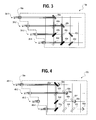
- FIG. 3 is a diagram illustrating an alternate configuration of the switch of FIG. 2;
- FIG. 4 is a diagram illustrating yet another configuration of the switch of FIG. 2.
- FIG. 5 is a multi-stage switch which incorporates switch modules in accordance herewith.
- Traffic reciprocity is defined as the condition where input B is connected to output A whenever input A is connected to output B.
- the exemplary connections illustrated in FIG. 1 do not correspond to reciprocal traffic. Specifically, input 1 is connected to output 2 whereas input 2 is not connected to output 1 as required by the definition of reciprocal traffic.
- the module 10 supports all traffic connections (both reciprocal and non-reciprocal), it provides greater flexibility than is required in applications where traffic reciprocity exists.
- the price of this flexibility is the requirement to have N 2 ⁇ 1 switchable deflectors or mirrors for an N ⁇ N switch.
- Switch module 10 a includes input/output ports 28 - 1 , - 2 , - 3 . . . -N. Each port is coupled to at least one source medium, such as an input optical fiber and at least one destination medium, an output fiber.
- module 10 a could be operated under the control of control circuits 10 a - 1 . These control circuits could be part of a larger communications system without departing from the spirit and scope of the present invention. It will also be understood that multiple reciprocal-traffic switches, such as module 10 a , can be included in larger single or multiple stage switches.
- each input/output port such as 28 - i
- a single coupled fiber could be used to carry bidirectional traffic.
- the gray rectangles 30 a , b, c . . . N denote fixed deflectors or mirrors. They always deflect an incident beam.
- Black rectangles 32 a , b denote actuated deflectors or mirrors and dashed rectangles 34 a, b, c denote non-actuated deflectors or mirrors.
- Deflectors 32 a , b and 34 a, b, c are all switchable between states.
- FIG. 2 illustrates an example where port 28 - 1 is coupled optically to port 28 - 4 and port 28 - 2 is coupled optically to port 28 - 3 .
- the forward path and the reverse path of the reciprocal traffic are deflected off the same deflectors or mirrors.
- FIG. 2 illustrates a 4 ⁇ 4 switch 10 a
- this architecture can be extended to an N ⁇ N switch module.
- the required number of switchable deflectors or mirrors is ⁇ N*(N ⁇ 1)/2 ⁇ 1. This is about half as many as those used by the crossbar module 10 .
- FIG. 2 An improvement can be made to the switch 10 a using staggered input and output ports 38 - 1 , - 2 , - 3 . . . -N as illustrated by switch 10 b , FIG. 3 .
- the path lengths of the paths are of unequal length. Path lengths are directly related to the amount of loss an optical signal incurs. The loss is due to the divergence of the light. The light diverges even in the presence of good collimating lenses. Therefore, it is desirable to make all path lengths equal, regardless of connection, in order to reduce the variability in insertion loss.
- Switch 10 b FIG. 3 provides equal path lengths.
- fixed and switchable deflectors are represented using the same conventions as used in FIG. 2 .
- Deflectors 40 a , b, c, d are fixed.
- Remaining deflectors 42 a , b, c, d, e are switchable.
- ports 38 - 1 and 38 - 3 are coupled together, and ports 38 - 2 and 38 - 4 are coupled together. These respective path lengths are of substantially the same length. Pairs of staggered input and output ports create equal length light paths, for example the connection between ports A and B where A ⁇ B.
- the deflectors used are the fixed deflectors on row A and the actuated deflector or mirror on row B.
- the fixed deflector or mirror is N units away from the input to port A.
- the actuated deflector or mirror is N ⁇ B+A units away from an input to port B.
- switch 10 c can be modified to include a loop-back function. Loop-back is present when an input at a port is to be coupled with the corresponding output at the same port.
- Adding a fixed deflector, such as a V-shaped mirror at the end of each row, such as deflectors 50 a, b, c, d provides a loop-back function.
- Deflectors 52 a, b, c . . . i are switchable.
- the constant path length property of module 10 b is almost preserved with the exception that loop-back paths are slightly longer.
- ports 48 - 1 and 48 - 4 are coupled together. Port 48 - 2 is looped-back on itself. Port 48 - 3 is unused.
- the number of switchable deflectors or mirrors for an N ⁇ N switch as in FIG. 4 is ⁇ N(N+1)/2 ⁇ 1. This is slightly larger than the number used by the switch 10 a of FIG. 2 without loop-back. However, it is still approximately one/half the number required by the switch 10 .
- the deflectors or mirrors can move in and out of position by using either a sliding or tilting mechanism. They could be non-moving multi-state solid state deflectors.
- the input and output fibers should be rested on V-grooves for better alignment with the collimating lenses.
- the lenses, deflectors or mirrors, and v-grooves may all be part of a MEMS (micro-electromechanical systems) platform. It will be understood that the details of implementation of the various deflectors or mirrors are not limitations of the present invention.
- Switch configurations such as 10 a , 10 b and 10 c can be used as building blocks to create larger multi-stage switches for reciprocal traffic.
- FIG. 5 illustrates an exemplary multi-stage switch 60 of a known type as disclosed in published PCT application WO 00/14583, assigned to the assignee hereof.
- the switch 60 employs two groups of switching modules 62 and 64 .
- the first group of modules 62 includes a plurality of (L,2L-1)-way modules 1-M.
- the (L,2L- 1)-way modules 62 can be implemented in a variety of ways, as would be understood by those of skill in the art and are not a limitation of the present invention.
- the second group of modules 64 includes a plurality of M-way reciprocal switching modules 1-2L-1.
- the M-way modules 64 can be implemented in accordance with the principles of any of the modules described above in connection with FIGS. 2-4.
- the modules 62 are connected to the modules 64 so the externally disposed I/O ports 66 handle reciprocal traffic in a non-blocking fashion. To this end, the modules are interconnected by optical fibers as illustrated in the exemplary switch 60 of FIG. 5 . It will be understood that a variety of switch architectures using modules 10 a , 10 b , 10 c , could be implemented in multi-stage switches to support reciprocal switch traffic without departing from the spirit and scope of the present invention.
Abstract
Description
Claims (43)
Priority Applications (7)
| Application Number | Priority Date | Filing Date | Title |
|---|---|---|---|
| US09/799,954 US6363182B2 (en) | 2000-07-31 | 2001-03-06 | Optical switch for reciprocal traffic |
| PCT/US2001/041465 WO2002010824A1 (en) | 2000-07-31 | 2001-07-30 | Optical switch for reciprocal traffic |
| AU2001277284A AU2001277284A1 (en) | 2000-07-31 | 2001-07-30 | Optical switch for reciprocal traffic |
| CA2416270A CA2416270C (en) | 2000-07-31 | 2001-07-30 | Optical switch for reciprocal traffic |
| EP01955083A EP1305663A4 (en) | 2000-07-31 | 2001-07-30 | Optical switch for reciprocal traffic |
| US10/037,054 US6650804B2 (en) | 2000-07-31 | 2002-01-03 | Optical switch for reciprocal traffic |
| US10/680,443 US6850662B1 (en) | 2000-07-31 | 2003-10-07 | Optical switch for reciprocal traffic |
Applications Claiming Priority (2)
| Application Number | Priority Date | Filing Date | Title |
|---|---|---|---|
| US22179600P | 2000-07-31 | 2000-07-31 | |
| US09/799,954 US6363182B2 (en) | 2000-07-31 | 2001-03-06 | Optical switch for reciprocal traffic |
Related Child Applications (1)
| Application Number | Title | Priority Date | Filing Date |
|---|---|---|---|
| US10/037,054 Continuation US6650804B2 (en) | 2000-07-31 | 2002-01-03 | Optical switch for reciprocal traffic |
Publications (2)
| Publication Number | Publication Date |
|---|---|
| US20020018614A1 US20020018614A1 (en) | 2002-02-14 |
| US6363182B2 true US6363182B2 (en) | 2002-03-26 |
Family
ID=26916146
Family Applications (2)
| Application Number | Title | Priority Date | Filing Date |
|---|---|---|---|
| US09/799,954 Expired - Lifetime US6363182B2 (en) | 2000-07-31 | 2001-03-06 | Optical switch for reciprocal traffic |
| US10/037,054 Expired - Fee Related US6650804B2 (en) | 2000-07-31 | 2002-01-03 | Optical switch for reciprocal traffic |
Family Applications After (1)
| Application Number | Title | Priority Date | Filing Date |
|---|---|---|---|
| US10/037,054 Expired - Fee Related US6650804B2 (en) | 2000-07-31 | 2002-01-03 | Optical switch for reciprocal traffic |
Country Status (5)
| Country | Link |
|---|---|
| US (2) | US6363182B2 (en) |
| EP (1) | EP1305663A4 (en) |
| AU (1) | AU2001277284A1 (en) |
| CA (1) | CA2416270C (en) |
| WO (1) | WO2002010824A1 (en) |
Cited By (19)
| Publication number | Priority date | Publication date | Assignee | Title |
|---|---|---|---|---|
| US6507421B1 (en) * | 1999-10-08 | 2003-01-14 | Lucent Technologies Inc. | Optical monitoring for OXC fabric |
| US20030048515A1 (en) * | 2001-08-28 | 2003-03-13 | Nec Corporation | Optical transmission system |
| US6549695B2 (en) * | 2001-06-05 | 2003-04-15 | Marconi Communications, Inc. | Method and apparatus for optically switching data |
| US6650804B2 (en) * | 2000-07-31 | 2003-11-18 | Tellabs Operations, Inc. | Optical switch for reciprocal traffic |
| US20030228090A1 (en) * | 2002-06-07 | 2003-12-11 | Advanced Optical Mems, Inc. | 2-D optical switch with lens mount |
| US20040047548A1 (en) * | 2002-07-09 | 2004-03-11 | Nec Corporation | Optical switching subsystem and optical switching subsystem self-diagnosing method |
| US20040151422A1 (en) * | 2003-02-05 | 2004-08-05 | Shah Manhar L. | Fiber-optic matrix switch using phased array acousto-optic device |
| US6823099B2 (en) * | 2001-03-07 | 2004-11-23 | Samsung Electronics Co., Ltd. | Optical bench |
| US20050041914A1 (en) * | 2000-12-20 | 2005-02-24 | Robert Anderson | Wavelength router with staggered input/output fibers |
| US20050201750A1 (en) * | 2003-09-10 | 2005-09-15 | Nabtesco Corporation | Optical path switching device |
| US20060018216A1 (en) * | 2004-07-26 | 2006-01-26 | Morris Terrel L | Apparatus and method of providing separate control and data channels between arrays of light emitters and detectors for optical communication and alignment |
| US20060034572A1 (en) * | 2004-08-10 | 2006-02-16 | Morris Terrel L | System and method of configuring fiber optic communication channels between arrays of emitters and detectors |
| US20060034609A1 (en) * | 2004-08-10 | 2006-02-16 | Morris Terrel L | System and method of self-configuring optical communication channels between arrays of emitters and detectors |
| US20060034560A1 (en) * | 2004-08-10 | 2006-02-16 | Morris Terrel L | Apparatus for providing optical communication between integrated circuits of different PC boads and an integrated circuit assembly for use therein |
| US20060034613A1 (en) * | 2004-08-10 | 2006-02-16 | Morris Terrel L | System and method of configuring fiber optic communication channels between arrays of emitters and detectors |
| US20060050754A1 (en) * | 2004-09-09 | 2006-03-09 | Morris Terrel L | Apparatus and method of establishing optical communication channels between a steerable array of laser emitters and an array of optical detectors |
| US20060062528A1 (en) * | 2004-09-20 | 2006-03-23 | Morris Terrel L | Apparatus and method of providing an optical connection between PC boards for optical communication |
| US20060126145A1 (en) * | 2004-12-09 | 2006-06-15 | Chen Jerry C | Methods and apparatus to make substantially uniform losses in optical cross connects |
| US9008510B1 (en) * | 2011-05-12 | 2015-04-14 | Google Inc. | Implementation of a large-scale multi-stage non-blocking optical circuit switch |
Families Citing this family (10)
| Publication number | Priority date | Publication date | Assignee | Title |
|---|---|---|---|---|
| US6850662B1 (en) * | 2000-07-31 | 2005-02-01 | Tellabs Operations, Inc. | Optical switch for reciprocal traffic |
| US7103243B2 (en) * | 2001-08-10 | 2006-09-05 | Japan Aviation Electronics Industry Limited | Optical switch |
| US6842555B2 (en) * | 2002-07-18 | 2005-01-11 | Analog Devices, Inc. | Method and apparatus for optical switching with same side input and outputs |
| JP2004233951A (en) * | 2002-12-02 | 2004-08-19 | Seiko Instruments Inc | Optical switch and optical switch device |
| US8307112B2 (en) * | 2003-07-31 | 2012-11-06 | Cloudsoft Corporation Limited | Mediated information flow |
| US7653305B1 (en) * | 2005-10-25 | 2010-01-26 | Lockheed Martin Corporation | Optical transport system and device |
| EP2030414B1 (en) * | 2006-06-12 | 2018-04-04 | Cloudsoft Corporation Limited | Self-managed distributed mediation networks |
| US20100074618A1 (en) * | 2006-08-03 | 2010-03-25 | Nabtesco Corporation | Optical path switching device |
| US9594216B1 (en) * | 2011-06-08 | 2017-03-14 | Alliance Fiber Optic Products, Inc. | Fiber optical switches |
| US11199665B2 (en) * | 2020-01-28 | 2021-12-14 | Hewlett Packard Enterprise Development Lp | Optical device for redirecting optical signals |
Citations (39)
| Publication number | Priority date | Publication date | Assignee | Title |
|---|---|---|---|---|
| US3823401A (en) | 1972-10-04 | 1974-07-09 | Data Transmission Co | Synchronous data transmission network |
| US4038497A (en) | 1975-05-12 | 1977-07-26 | Collins Arthur A | Hardwired marker for time folded tst switch with distributed control logic and automatic path finding, set up and release |
| US4239329A (en) | 1978-08-04 | 1980-12-16 | Nippon Telegraph And Telephone Public Corporation | Optical nonreciprocal device |
| US4289373A (en) | 1978-08-17 | 1981-09-15 | Nippon Electric Co., Ltd. | Bidirectional optical fiber transmission system |
| US4493113A (en) | 1982-09-10 | 1985-01-08 | At&T Bell Laboratories | Bidirectional fiber optic transmission systems and photodiodes for use in such systems |
| DE3335128A1 (en) | 1983-09-28 | 1985-04-11 | Siemens AG, 1000 Berlin und 8000 München | MOBILE RADIO NETWORK |
| US4684796A (en) | 1983-07-08 | 1987-08-04 | The Charles Stark Draper Laboratory, Inc. | Common optical aperture laser separator for reciprocal path optical |
| US4787692A (en) | 1987-03-13 | 1988-11-29 | American Telephone And Telegraph Company At&T Bell Laboratories | Electro optical switch architectures |
| US4846542A (en) | 1987-10-09 | 1989-07-11 | Oki Electric Industry Co., Ltd. | Optical switch matrix |
| US4889404A (en) | 1987-09-09 | 1989-12-26 | Corning Incorporated | Asymmetrical bidirectional telecommunication system |
| US5009477A (en) | 1989-05-12 | 1991-04-23 | At&T Bell Laboratories | Optical interconnect arrangement |
| US5048910A (en) | 1990-05-08 | 1991-09-17 | Amp Incorporated | Optical matrix switch for multiple input/output port configurations |
| US5077483A (en) | 1989-05-08 | 1991-12-31 | At&T Bell Laboratories | Network topology for reduced blocking and photonic system implementation thereof |
| US5146358A (en) | 1990-01-25 | 1992-09-08 | Pyr Systems, Inc. | Optical communications system and method for transmitting information through a single optical waveguide |
| US5255332A (en) | 1992-07-16 | 1993-10-19 | Sdl, Inc. | NxN Optical crossbar switch matrix |
| US5272555A (en) | 1990-10-26 | 1993-12-21 | Nec Corporation | Bidirectional optical transmission method and apparatus therefor |
| US5274487A (en) | 1989-12-29 | 1993-12-28 | Fujitsu Limited | Photonic switching system |
| US5301008A (en) * | 1991-11-05 | 1994-04-05 | At&T Bell Laboratories | Optical crossbar exchange arrangement |
| US5343314A (en) | 1988-10-04 | 1994-08-30 | Canon Kabushiki Kaisha | Optical fiber communication method and multimedia optical fiber network using the same |
| US5359683A (en) | 1993-06-10 | 1994-10-25 | Advanced Optronics, Inc. | 1×N electromechanical optical switch |
| US5408350A (en) | 1991-10-04 | 1995-04-18 | Alcatel Cit | Bidirectional transmission system, especially one using optical fiber, employing a single carrier for both transmission directions |
| US5416662A (en) | 1992-06-10 | 1995-05-16 | Kurasawa; Koichi | Chip-type surge absorber |
| US5469277A (en) | 1992-02-07 | 1995-11-21 | University Of Ottawa | Optical interconnection device |
| US5471340A (en) | 1994-01-07 | 1995-11-28 | Jds Fitel Inc. | Reflective optical non-reciprocal devices |
| US5552918A (en) | 1994-10-06 | 1996-09-03 | Siemens Aktiengesellschaft | Transmission and reception module for a bidirectional optical communication and signal transmission |
| US5588078A (en) | 1993-12-10 | 1996-12-24 | Jds Fitel Inc. | Non-reciprocal optical waveguide coupling device |
| US5608565A (en) | 1994-06-14 | 1997-03-04 | Nippon Telegraph And Telephone Corporation | Bidirectional optical transmission system |
| US5623562A (en) | 1994-04-05 | 1997-04-22 | Tektronix, Inc. | Method of aligning opposing optical transmission paths in a mechanical optical switch |
| US5648963A (en) | 1991-10-07 | 1997-07-15 | Fujitsu Limited | Input and output side conversion interfaces for an ATM exchange |
| US5652813A (en) | 1995-03-31 | 1997-07-29 | The Whitaker Corporation | Line bi-directional link |
| US5663818A (en) | 1992-10-15 | 1997-09-02 | Canon Kabushiki Kaisha | Optical concentrator and optical communication network using the same |
| US5680234A (en) | 1994-10-20 | 1997-10-21 | Lucent Technologies Inc. | Passive optical network with bi-directional optical spectral slicing and loop-back |
| US5712932A (en) | 1995-08-08 | 1998-01-27 | Ciena Corporation | Dynamically reconfigurable WDM optical communication systems with optical routing systems |
| US5729642A (en) | 1995-10-02 | 1998-03-17 | The Boeing Company | N×N optical switch array using electro-optic and passive waveguide circuits on planar substrates |
| US5734763A (en) | 1996-09-04 | 1998-03-31 | Hewlett-Packard Company | Compact two-by-n optical components based on bierfringent walk-off crystals |
| US5739933A (en) | 1995-06-02 | 1998-04-14 | Alcatel N.V. | Optically controlled optical switching module, method of optically controlling an optical switching network, and optical switching network |
| US5742717A (en) | 1995-10-30 | 1998-04-21 | Fuji Electric Co., Ltd. | Optical star coupler |
| US6282336B1 (en) * | 1999-09-24 | 2001-08-28 | Light Bytes, Inc. | High speed fiber-optic switch |
| US6292281B1 (en) * | 1999-03-24 | 2001-09-18 | Tellium, Inc. | Protection for MEMS cross-bar switch |
Family Cites Families (22)
| Publication number | Priority date | Publication date | Assignee | Title |
|---|---|---|---|---|
| US4904042A (en) | 1988-05-03 | 1990-02-27 | American Telephone And Telegraph Company | N×N optical star coupler |
| US5208880A (en) | 1992-04-30 | 1993-05-04 | General Electric Company | Microdynamical fiber-optic switch and method of switching using same |
| US5642446A (en) | 1993-03-09 | 1997-06-24 | Tsai; Jian-Hung | Apparatus for switching optical signals among optical fibers |
| US6044705A (en) | 1993-10-18 | 2000-04-04 | Xros, Inc. | Micromachined members coupled for relative rotation by torsion bars |
| US5524153A (en) | 1995-02-10 | 1996-06-04 | Astarte Fiber Networks, Inc. | Optical fiber switching system and method using same |
| US5841917A (en) | 1997-01-31 | 1998-11-24 | Hewlett-Packard Company | Optical cross-connect switch using a pin grid actuator |
| US5943454A (en) | 1997-08-15 | 1999-08-24 | Lucent Technologies, Inc. | Freespace optical bypass-exchange switch |
| US5960132A (en) | 1997-09-09 | 1999-09-28 | At&T Corp. | Fiber-optic free-space micromachined matrix switches |
| US6002818A (en) | 1997-12-05 | 1999-12-14 | Lucent Technologies Inc | Free-space optical signal switch arrangement |
| US5994159A (en) | 1997-12-22 | 1999-11-30 | Lucent Technologies, Inc. | Self-assemblying micro-mechanical device |
| US6212309B1 (en) | 1998-01-24 | 2001-04-03 | Mitel Corporation | Optical cross point switch using deformable micromirror |
| US6005998A (en) | 1998-02-20 | 1999-12-21 | Lucent Technologies Inc. | Strictly non-blocking scalable matrix optical switch |
| RU2267143C2 (en) * | 1998-06-05 | 2005-12-27 | Эй Эф Эн Ллк | Optical switch( variants ), optical switching device( variants ) and mode of switching of an optical signal |
| US6366713B1 (en) | 1998-09-04 | 2002-04-02 | Tellabs Operations, Inc. | Strictly non-blocking optical switch core having optimized switching architecture based on reciprocity conditions |
| US6278812B1 (en) | 1998-12-14 | 2001-08-21 | At&T Corporation | Protection schemes for mirror-failure in free-space micromachined optical switches |
| US6317532B1 (en) | 1998-12-15 | 2001-11-13 | At&T Corp. | Method and apparatus for low loss via geometrical optimization in free-space micro-machined optical switches |
| US6259833B1 (en) | 1999-01-15 | 2001-07-10 | Lucent Technologies Inc. | Optical cross connect using a planar arrangement of beam steerers |
| US6445841B1 (en) | 1999-05-28 | 2002-09-03 | Omm, Inc. | Optomechanical matrix switches including collimator arrays |
| US6292600B1 (en) | 1999-06-07 | 2001-09-18 | At&T Corp. | Angular-precision enhancement in free-space micromachined optical switches |
| US6473544B1 (en) | 2000-03-03 | 2002-10-29 | Onix Microsystems, Inc. | Optical switch having equalized beam spreading in all connections |
| US20010040419A1 (en) | 2000-03-24 | 2001-11-15 | Behrang Behin | Biased rotatable combdrive sensor methods |
| US6363182B2 (en) * | 2000-07-31 | 2002-03-26 | James D. Mills | Optical switch for reciprocal traffic |
-
2001
- 2001-03-06 US US09/799,954 patent/US6363182B2/en not_active Expired - Lifetime
- 2001-07-30 WO PCT/US2001/041465 patent/WO2002010824A1/en active Application Filing
- 2001-07-30 EP EP01955083A patent/EP1305663A4/en not_active Withdrawn
- 2001-07-30 AU AU2001277284A patent/AU2001277284A1/en not_active Abandoned
- 2001-07-30 CA CA2416270A patent/CA2416270C/en not_active Expired - Fee Related
-
2002
- 2002-01-03 US US10/037,054 patent/US6650804B2/en not_active Expired - Fee Related
Patent Citations (39)
| Publication number | Priority date | Publication date | Assignee | Title |
|---|---|---|---|---|
| US3823401A (en) | 1972-10-04 | 1974-07-09 | Data Transmission Co | Synchronous data transmission network |
| US4038497A (en) | 1975-05-12 | 1977-07-26 | Collins Arthur A | Hardwired marker for time folded tst switch with distributed control logic and automatic path finding, set up and release |
| US4239329A (en) | 1978-08-04 | 1980-12-16 | Nippon Telegraph And Telephone Public Corporation | Optical nonreciprocal device |
| US4289373A (en) | 1978-08-17 | 1981-09-15 | Nippon Electric Co., Ltd. | Bidirectional optical fiber transmission system |
| US4493113A (en) | 1982-09-10 | 1985-01-08 | At&T Bell Laboratories | Bidirectional fiber optic transmission systems and photodiodes for use in such systems |
| US4684796A (en) | 1983-07-08 | 1987-08-04 | The Charles Stark Draper Laboratory, Inc. | Common optical aperture laser separator for reciprocal path optical |
| DE3335128A1 (en) | 1983-09-28 | 1985-04-11 | Siemens AG, 1000 Berlin und 8000 München | MOBILE RADIO NETWORK |
| US4787692A (en) | 1987-03-13 | 1988-11-29 | American Telephone And Telegraph Company At&T Bell Laboratories | Electro optical switch architectures |
| US4889404A (en) | 1987-09-09 | 1989-12-26 | Corning Incorporated | Asymmetrical bidirectional telecommunication system |
| US4846542A (en) | 1987-10-09 | 1989-07-11 | Oki Electric Industry Co., Ltd. | Optical switch matrix |
| US5343314A (en) | 1988-10-04 | 1994-08-30 | Canon Kabushiki Kaisha | Optical fiber communication method and multimedia optical fiber network using the same |
| US5077483A (en) | 1989-05-08 | 1991-12-31 | At&T Bell Laboratories | Network topology for reduced blocking and photonic system implementation thereof |
| US5009477A (en) | 1989-05-12 | 1991-04-23 | At&T Bell Laboratories | Optical interconnect arrangement |
| US5274487A (en) | 1989-12-29 | 1993-12-28 | Fujitsu Limited | Photonic switching system |
| US5146358A (en) | 1990-01-25 | 1992-09-08 | Pyr Systems, Inc. | Optical communications system and method for transmitting information through a single optical waveguide |
| US5048910A (en) | 1990-05-08 | 1991-09-17 | Amp Incorporated | Optical matrix switch for multiple input/output port configurations |
| US5272555A (en) | 1990-10-26 | 1993-12-21 | Nec Corporation | Bidirectional optical transmission method and apparatus therefor |
| US5408350A (en) | 1991-10-04 | 1995-04-18 | Alcatel Cit | Bidirectional transmission system, especially one using optical fiber, employing a single carrier for both transmission directions |
| US5648963A (en) | 1991-10-07 | 1997-07-15 | Fujitsu Limited | Input and output side conversion interfaces for an ATM exchange |
| US5301008A (en) * | 1991-11-05 | 1994-04-05 | At&T Bell Laboratories | Optical crossbar exchange arrangement |
| US5469277A (en) | 1992-02-07 | 1995-11-21 | University Of Ottawa | Optical interconnection device |
| US5416662A (en) | 1992-06-10 | 1995-05-16 | Kurasawa; Koichi | Chip-type surge absorber |
| US5255332A (en) | 1992-07-16 | 1993-10-19 | Sdl, Inc. | NxN Optical crossbar switch matrix |
| US5663818A (en) | 1992-10-15 | 1997-09-02 | Canon Kabushiki Kaisha | Optical concentrator and optical communication network using the same |
| US5359683A (en) | 1993-06-10 | 1994-10-25 | Advanced Optronics, Inc. | 1×N electromechanical optical switch |
| US5588078A (en) | 1993-12-10 | 1996-12-24 | Jds Fitel Inc. | Non-reciprocal optical waveguide coupling device |
| US5471340A (en) | 1994-01-07 | 1995-11-28 | Jds Fitel Inc. | Reflective optical non-reciprocal devices |
| US5623562A (en) | 1994-04-05 | 1997-04-22 | Tektronix, Inc. | Method of aligning opposing optical transmission paths in a mechanical optical switch |
| US5608565A (en) | 1994-06-14 | 1997-03-04 | Nippon Telegraph And Telephone Corporation | Bidirectional optical transmission system |
| US5552918A (en) | 1994-10-06 | 1996-09-03 | Siemens Aktiengesellschaft | Transmission and reception module for a bidirectional optical communication and signal transmission |
| US5680234A (en) | 1994-10-20 | 1997-10-21 | Lucent Technologies Inc. | Passive optical network with bi-directional optical spectral slicing and loop-back |
| US5652813A (en) | 1995-03-31 | 1997-07-29 | The Whitaker Corporation | Line bi-directional link |
| US5739933A (en) | 1995-06-02 | 1998-04-14 | Alcatel N.V. | Optically controlled optical switching module, method of optically controlling an optical switching network, and optical switching network |
| US5712932A (en) | 1995-08-08 | 1998-01-27 | Ciena Corporation | Dynamically reconfigurable WDM optical communication systems with optical routing systems |
| US5729642A (en) | 1995-10-02 | 1998-03-17 | The Boeing Company | N×N optical switch array using electro-optic and passive waveguide circuits on planar substrates |
| US5742717A (en) | 1995-10-30 | 1998-04-21 | Fuji Electric Co., Ltd. | Optical star coupler |
| US5734763A (en) | 1996-09-04 | 1998-03-31 | Hewlett-Packard Company | Compact two-by-n optical components based on bierfringent walk-off crystals |
| US6292281B1 (en) * | 1999-03-24 | 2001-09-18 | Tellium, Inc. | Protection for MEMS cross-bar switch |
| US6282336B1 (en) * | 1999-09-24 | 2001-08-28 | Light Bytes, Inc. | High speed fiber-optic switch |
Non-Patent Citations (4)
| Title |
|---|
| Hirabayashi et al. "Optical Beam Direction Compensating System for Board-to-Board Free Space Optical Interconnection in High-Capacity ATM Switch", Lightwave Technology, Journal of, vol.: 15, May 1997, pp. 874-882.* |
| U.S. application No. 09/143,335, Lin et al., filed Sep. 4, 1998. |
| U.S. application No. 09/322,337, Magill et al., filed May 28, 1999. |
| Yamaguchi et al. "High-density free-space photonic switching fabrics", IEEE, vol. 1, 1995, pp. 61-62.* |
Cited By (37)
| Publication number | Priority date | Publication date | Assignee | Title |
|---|---|---|---|---|
| US6507421B1 (en) * | 1999-10-08 | 2003-01-14 | Lucent Technologies Inc. | Optical monitoring for OXC fabric |
| US6650804B2 (en) * | 2000-07-31 | 2003-11-18 | Tellabs Operations, Inc. | Optical switch for reciprocal traffic |
| US6873755B2 (en) * | 2000-12-20 | 2005-03-29 | Pts Corporation | Wavelength router with staggered input/output fibers |
| US20050041914A1 (en) * | 2000-12-20 | 2005-02-24 | Robert Anderson | Wavelength router with staggered input/output fibers |
| US6823099B2 (en) * | 2001-03-07 | 2004-11-23 | Samsung Electronics Co., Ltd. | Optical bench |
| US6549695B2 (en) * | 2001-06-05 | 2003-04-15 | Marconi Communications, Inc. | Method and apparatus for optically switching data |
| US7095962B2 (en) * | 2001-08-28 | 2006-08-22 | Denso Corporation | Optical transmission system |
| US20030048515A1 (en) * | 2001-08-28 | 2003-03-13 | Nec Corporation | Optical transmission system |
| US20030228090A1 (en) * | 2002-06-07 | 2003-12-11 | Advanced Optical Mems, Inc. | 2-D optical switch with lens mount |
| US6937783B2 (en) | 2002-06-07 | 2005-08-30 | Charles Chu | 2-D optical switch with lens mount |
| US20040047548A1 (en) * | 2002-07-09 | 2004-03-11 | Nec Corporation | Optical switching subsystem and optical switching subsystem self-diagnosing method |
| US20040151422A1 (en) * | 2003-02-05 | 2004-08-05 | Shah Manhar L. | Fiber-optic matrix switch using phased array acousto-optic device |
| US6922498B2 (en) | 2003-02-05 | 2005-07-26 | Mvm Electronics, Inc. | Fiber-optic matrix switch using phased array acousto-optic device |
| US7561799B2 (en) * | 2003-09-10 | 2009-07-14 | Nabtesco Corporation | Optical path switching device |
| US20050201750A1 (en) * | 2003-09-10 | 2005-09-15 | Nabtesco Corporation | Optical path switching device |
| US20060018216A1 (en) * | 2004-07-26 | 2006-01-26 | Morris Terrel L | Apparatus and method of providing separate control and data channels between arrays of light emitters and detectors for optical communication and alignment |
| US7809278B2 (en) | 2004-07-26 | 2010-10-05 | Hewlett-Packard Development Company, L.P. | Apparatus and method of providing separate control and data channels between arrays of light emitters and detectors for optical communication and alignment |
| US7623793B2 (en) | 2004-08-10 | 2009-11-24 | Hewlett-Packard Development Company, L.P. | System and method of configuring fiber optic communication channels between arrays of emitters and detectors |
| US20060034572A1 (en) * | 2004-08-10 | 2006-02-16 | Morris Terrel L | System and method of configuring fiber optic communication channels between arrays of emitters and detectors |
| US20060034609A1 (en) * | 2004-08-10 | 2006-02-16 | Morris Terrel L | System and method of self-configuring optical communication channels between arrays of emitters and detectors |
| US20060034613A1 (en) * | 2004-08-10 | 2006-02-16 | Morris Terrel L | System and method of configuring fiber optic communication channels between arrays of emitters and detectors |
| US7251388B2 (en) | 2004-08-10 | 2007-07-31 | Hewlett-Packard Development Company, L.P. | Apparatus for providing optical communication between integrated circuits of different PC boards and an integrated circuit assembly for use therein |
| US7269321B2 (en) | 2004-08-10 | 2007-09-11 | Hewlett-Packard Development Company, L.P. | System and method of configuring fiber optic communication channels between arrays of emitters and detectors |
| US20060034560A1 (en) * | 2004-08-10 | 2006-02-16 | Morris Terrel L | Apparatus for providing optical communication between integrated circuits of different PC boads and an integrated circuit assembly for use therein |
| US7623783B2 (en) | 2004-08-10 | 2009-11-24 | Hewlett-Packard Development Company, L.P. | System and method of self-configuring optical communication channels between arrays of emitters and detectors |
| US9142938B2 (en) | 2004-09-09 | 2015-09-22 | Hewlett-Packard Development Company, L.P. | Apparatus and method of establishing optical communication channels between a steerable array of laser emitters and an array of optical detectors |
| US20060050754A1 (en) * | 2004-09-09 | 2006-03-09 | Morris Terrel L | Apparatus and method of establishing optical communication channels between a steerable array of laser emitters and an array of optical detectors |
| US20100074294A1 (en) * | 2004-09-09 | 2010-03-25 | Morris Terrel L | Apparatus and method of establishing optical communication channels between a steerable array of laser emitters and an array of optical detectors |
| US7653108B2 (en) | 2004-09-09 | 2010-01-26 | Hewlett-Packard Development Company, L.P. | Apparatus and method of establishing optical communication channels between a steerable array of laser emitters and an array of optical detectors |
| US7229218B2 (en) | 2004-09-20 | 2007-06-12 | Hewlett-Packard Development Company, L.P. | Apparatus and method of providing an optical connection between PC boards for optical communication |
| US20060062528A1 (en) * | 2004-09-20 | 2006-03-23 | Morris Terrel L | Apparatus and method of providing an optical connection between PC boards for optical communication |
| US7623744B2 (en) * | 2004-12-09 | 2009-11-24 | Tellabs Operations, Inc. | Methods and apparatus to make substantially uniform losses in optical cross connects |
| US20080292241A1 (en) * | 2004-12-09 | 2008-11-27 | Tellabs Operations. Inc. | Methods and Apparatus to Make Substantially Uniform Losses in Optical Cross Connects |
| US7400792B2 (en) | 2004-12-09 | 2008-07-15 | Tellabs Operations, Inc. | Methods and apparatus to make substantially uniform losses in optical cross connects |
| US20060126145A1 (en) * | 2004-12-09 | 2006-06-15 | Chen Jerry C | Methods and apparatus to make substantially uniform losses in optical cross connects |
| US9008510B1 (en) * | 2011-05-12 | 2015-04-14 | Google Inc. | Implementation of a large-scale multi-stage non-blocking optical circuit switch |
| US9210487B1 (en) | 2011-05-12 | 2015-12-08 | Google Inc. | Implementation of a large-scale multi-stage non-blocking optical circuit switch |
Also Published As
| Publication number | Publication date |
|---|---|
| WO2002010824A1 (en) | 2002-02-07 |
| US20020018614A1 (en) | 2002-02-14 |
| EP1305663A1 (en) | 2003-05-02 |
| EP1305663A4 (en) | 2007-09-19 |
| US20020057864A1 (en) | 2002-05-16 |
| CA2416270C (en) | 2011-04-26 |
| US6650804B2 (en) | 2003-11-18 |
| CA2416270A1 (en) | 2002-02-07 |
| AU2001277284A1 (en) | 2002-02-13 |
Similar Documents
| Publication | Publication Date | Title |
|---|---|---|
| US6363182B2 (en) | Optical switch for reciprocal traffic | |
| US6614953B2 (en) | Modular all-optical cross-connect | |
| US7088882B2 (en) | Wavelength cross-connect | |
| US8233794B2 (en) | Hitless MxN wavelength selective switch | |
| US7206476B2 (en) | Optical switch | |
| US6219474B1 (en) | Configurable optical add/drop device | |
| US20020061158A1 (en) | Optical switch | |
| EP0898440A2 (en) | Optical switch module | |
| US8218918B2 (en) | Optical fiber switch with movable lens | |
| US6850662B1 (en) | Optical switch for reciprocal traffic | |
| US7039267B2 (en) | Optical switch | |
| US6134357A (en) | Optical switching system | |
| US20030016904A1 (en) | Optical switch device | |
| US6415069B1 (en) | Optical switching modules and systems | |
| US7162118B1 (en) | Dual optical switch | |
| US20020061161A1 (en) | Optical switch | |
| US6859578B2 (en) | Fault-tolerant fiber-optical multiwavelength processor | |
| CA2245599C (en) | Optical switch module | |
| US20020085793A1 (en) | Optical switch | |
| CA2363526C (en) | Optical switch | |
| EP1365267A1 (en) | An optical switch unit and a method therefore | |
| CN117170025A (en) | Wavelength selective switch and optical signal processing method | |
| Doerr | Degree-4 node using a single wavelength-selective switch | |
| EP0916982A2 (en) | Optical switch | |
| CA2363625A1 (en) | Optical switch |
Legal Events
| Date | Code | Title | Description |
|---|---|---|---|
| AS | Assignment |
Owner name: TELLABS OPERATIONS, INC., ILLINOIS Free format text: ASSIGNMENT OF ASSIGNORS INTEREST;ASSIGNORS:MILLS, JAMES D.;LIN, PHILIP J.;HOLMSTROM, ROGER P.;REEL/FRAME:011745/0090;SIGNING DATES FROM 20010226 TO 20010302 |
|
| STCF | Information on status: patent grant |
Free format text: PATENTED CASE |
|
| FPAY | Fee payment |
Year of fee payment: 4 |
|
| FPAY | Fee payment |
Year of fee payment: 8 |
|
| FPAY | Fee payment |
Year of fee payment: 12 |
|
| AS | Assignment |
Owner name: CERBERUS BUSINESS FINANCE, LLC, AS COLLATERAL AGEN Free format text: SECURITY AGREEMENT;ASSIGNORS:TELLABS OPERATIONS, INC.;TELLABS RESTON, LLC (FORMERLY KNOWN AS TELLABS RESTON, INC.);WICHORUS, LLC (FORMERLY KNOWN AS WICHORUS, INC.);REEL/FRAME:031768/0155 Effective date: 20131203 |
|
| AS | Assignment |
Owner name: TELECOM HOLDING PARENT LLC, CALIFORNIA Free format text: ASSIGNMENT FOR SECURITY - - PATENTS;ASSIGNORS:CORIANT OPERATIONS, INC.;TELLABS RESTON, LLC (FORMERLY KNOWN AS TELLABS RESTON, INC.);WICHORUS, LLC (FORMERLY KNOWN AS WICHORUS, INC.);REEL/FRAME:034484/0740 Effective date: 20141126 |
|
| AS | Assignment |
Owner name: TELECOM HOLDING PARENT LLC, CALIFORNIA Free format text: CORRECTIVE ASSIGNMENT TO CORRECT THE REMOVE APPLICATION NUMBER 10/075,623 PREVIOUSLY RECORDED AT REEL: 034484 FRAME: 0740. ASSIGNOR(S) HEREBY CONFIRMS THE ASSIGNMENT FOR SECURITY --- PATENTS;ASSIGNORS:CORIANT OPERATIONS, INC.;TELLABS RESTON, LLC (FORMERLY KNOWN AS TELLABS RESTON, INC.);WICHORUS, LLC (FORMERLY KNOWN AS WICHORUS, INC.);REEL/FRAME:042980/0834 Effective date: 20141126 |