US6360338B1 - Enhanced instrumentation software in fault tolerant systems - Google Patents
Enhanced instrumentation software in fault tolerant systems Download PDFInfo
- Publication number
- US6360338B1 US6360338B1 US08/377,390 US37739095A US6360338B1 US 6360338 B1 US6360338 B1 US 6360338B1 US 37739095 A US37739095 A US 37739095A US 6360338 B1 US6360338 B1 US 6360338B1
- Authority
- US
- United States
- Prior art keywords
- exporter
- processes
- service
- monitoring
- monitor
- Prior art date
- Legal status (The legal status is an assumption and is not a legal conclusion. Google has not performed a legal analysis and makes no representation as to the accuracy of the status listed.)
- Expired - Fee Related
Links
Images


Classifications
-
- G—PHYSICS
- G06—COMPUTING; CALCULATING OR COUNTING
- G06F—ELECTRIC DIGITAL DATA PROCESSING
- G06F11/00—Error detection; Error correction; Monitoring
- G06F11/07—Responding to the occurrence of a fault, e.g. fault tolerance
- G06F11/16—Error detection or correction of the data by redundancy in hardware
- G06F11/20—Error detection or correction of the data by redundancy in hardware using active fault-masking, e.g. by switching out faulty elements or by switching in spare elements
- G06F11/202—Error detection or correction of the data by redundancy in hardware using active fault-masking, e.g. by switching out faulty elements or by switching in spare elements where processing functionality is redundant
- G06F11/2023—Failover techniques
- G06F11/2025—Failover techniques using centralised failover control functionality
-
- G—PHYSICS
- G06—COMPUTING; CALCULATING OR COUNTING
- G06F—ELECTRIC DIGITAL DATA PROCESSING
- G06F11/00—Error detection; Error correction; Monitoring
- G06F11/07—Responding to the occurrence of a fault, e.g. fault tolerance
- G06F11/16—Error detection or correction of the data by redundancy in hardware
- G06F11/20—Error detection or correction of the data by redundancy in hardware using active fault-masking, e.g. by switching out faulty elements or by switching in spare elements
- G06F11/202—Error detection or correction of the data by redundancy in hardware using active fault-masking, e.g. by switching out faulty elements or by switching in spare elements where processing functionality is redundant
- G06F11/2035—Error detection or correction of the data by redundancy in hardware using active fault-masking, e.g. by switching out faulty elements or by switching in spare elements where processing functionality is redundant without idle spare hardware
-
- G—PHYSICS
- G06—COMPUTING; CALCULATING OR COUNTING
- G06F—ELECTRIC DIGITAL DATA PROCESSING
- G06F11/00—Error detection; Error correction; Monitoring
- G06F11/30—Monitoring
- G06F11/3003—Monitoring arrangements specially adapted to the computing system or computing system component being monitored
- G06F11/3006—Monitoring arrangements specially adapted to the computing system or computing system component being monitored where the computing system is distributed, e.g. networked systems, clusters, multiprocessor systems
-
- G—PHYSICS
- G06—COMPUTING; CALCULATING OR COUNTING
- G06F—ELECTRIC DIGITAL DATA PROCESSING
- G06F11/00—Error detection; Error correction; Monitoring
- G06F11/30—Monitoring
- G06F11/3003—Monitoring arrangements specially adapted to the computing system or computing system component being monitored
- G06F11/3017—Monitoring arrangements specially adapted to the computing system or computing system component being monitored where the computing system is implementing multitasking
-
- G—PHYSICS
- G06—COMPUTING; CALCULATING OR COUNTING
- G06F—ELECTRIC DIGITAL DATA PROCESSING
- G06F11/00—Error detection; Error correction; Monitoring
- G06F11/30—Monitoring
- G06F11/3003—Monitoring arrangements specially adapted to the computing system or computing system component being monitored
- G06F11/302—Monitoring arrangements specially adapted to the computing system or computing system component being monitored where the computing system component is a software system
-
- G—PHYSICS
- G06—COMPUTING; CALCULATING OR COUNTING
- G06F—ELECTRIC DIGITAL DATA PROCESSING
- G06F11/00—Error detection; Error correction; Monitoring
- G06F11/30—Monitoring
- G06F11/3055—Monitoring arrangements for monitoring the status of the computing system or of the computing system component, e.g. monitoring if the computing system is on, off, available, not available
-
- G—PHYSICS
- G06—COMPUTING; CALCULATING OR COUNTING
- G06F—ELECTRIC DIGITAL DATA PROCESSING
- G06F11/00—Error detection; Error correction; Monitoring
- G06F11/30—Monitoring
- G06F11/3089—Monitoring arrangements determined by the means or processing involved in sensing the monitored data, e.g. interfaces, connectors, sensors, probes, agents
- G06F11/3093—Configuration details thereof, e.g. installation, enabling, spatial arrangement of the probes
-
- G—PHYSICS
- G06—COMPUTING; CALCULATING OR COUNTING
- G06F—ELECTRIC DIGITAL DATA PROCESSING
- G06F11/00—Error detection; Error correction; Monitoring
- G06F11/30—Monitoring
- G06F11/34—Recording or statistical evaluation of computer activity, e.g. of down time, of input/output operation ; Recording or statistical evaluation of user activity, e.g. usability assessment
- G06F11/3466—Performance evaluation by tracing or monitoring
- G06F11/3495—Performance evaluation by tracing or monitoring for systems
-
- H—ELECTRICITY
- H04—ELECTRIC COMMUNICATION TECHNIQUE
- H04L—TRANSMISSION OF DIGITAL INFORMATION, e.g. TELEGRAPHIC COMMUNICATION
- H04L43/00—Arrangements for monitoring or testing data switching networks
-
- G—PHYSICS
- G06—COMPUTING; CALCULATING OR COUNTING
- G06F—ELECTRIC DIGITAL DATA PROCESSING
- G06F2201/00—Indexing scheme relating to error detection, to error correction, and to monitoring
- G06F2201/865—Monitoring of software
Definitions
- This invention deals generally with software in fault tolerant systems and specifically with fault tolerant instrumentation software for monitoring multiple processes in a distributed multi-processing network.
- Monitoring and control of data plays an important role in today's computer systems.
- large computer systems deal with large amounts of information, as in, for example, a distributed transaction-based data base system
- the ability to receive information from any of a number of processes that make up the data base service and the ability to control or otherwise affect the operation of the service processes has advantages.
- One advantage is, that the system can be selectively monitored by a human or an automated management system such as another computer system.
- Another advantage is that the operation of the system can be affected in real time without bringing the system to a halt to load in and execute modified software to implement the services or processes.
- Monitoring and control of software in real time is also referred to as “instrumenting” the software being executed.
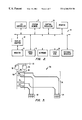
- FIG. 1 shows a generalized computer network 10 that includes several processors such as processor 12 , processor 14 , etc.
- Each processor typically includes a central processing unit (CPU), random access memory (RAM), disk drive, etc.
- the processors may be any type of processor or computer system as is commonly known in the art.
- the processors typically execute software to perform tasks.
- the software can be thought of in terms of singular “processes” and are shown as circles within the processor rectangles such as process 22 within processor 16 .
- a process such as process 22 may be an operating system process, application program process, etc. and can perform tasks such as math computations, data base manipulation, communication task, etc.
- processes can be split up over several processors so that multi-processing takes place.
- process 22 can be part of a graphics-rendering task in which processes 24 , 26 and 28 are also participating.
- it is often irrelevant where a certain process is executing.
- Processes can communicate with other processes by sending messages over the network. For example, in FIG. 1, message 30 is being transferred over network 32 from process 22 to process 28 .
- the processes reside, respectively, on processor 16 and processor 20 .
- Message 30 may be, for example, a packet of data if the generalized network 10 is a packet switch network.
- network 32 may be any type of network. Further, the interconnections between processors may be by hardwire, radiowave, fiber optic, or other types of connections. The ability of processes on different processors to communicate quickly and efficiently over network 32 is very important toward realizing an efficient distributed network.
- a processor such as processor 20 in FIG. 1, may have specific hardware attached to it to perform tasks such as interfacing with a human.
- Processor 20 is shown to have a display 32 and keyboard 34 for performing, respectively, output and input to a human user.
- Such devices are useful, for example, to allow a human to monitor and control whatever tasks are being performed by the various processors and processes attached to network 32 .
- One example of a task or “service” is a distributed data base system where multiple users at multiple processors can be connected to multiple other processors for purposes of accessing a data base that resides on storage media connected to the network.
- FIG. 1 it is assumed that each processor has some of its own resources, such as RAM and other storage media. However, typically a network will provide shared resources such as a large disk array that can be accessed by any of the processors in turn.
- processor 20 is executing a process, such as process 28 , to implement a monitoring and control function so that a user operating keyboard 34 and viewing display 32 can receive information on, and transfer information to, various processes in the network
- a process such as process 28
- process 28 is monitoring process 22 so that process 28 receives information from process 22 in the form of messages such as message 30 sent, from time to time, from process 22 to process 28 .
- process 28 would receive messages containing information on the state or status of process 22 and display this information to a user on display 32 .
- messages can be transferred in the other direction from process 28 to process 22 in response to a user's input at keyboard 34 .
- the messages from the monitoring and control process 28 to the monitored and controlled process 22 could change the way process 22 operates.
- process 22 would cease to transmit messages and would also cease to receive and act upon messages. For such a failure is not catastrophic to the operation of the network, or service provided by the network system, such a failure of processor 16 , and inability of process 22 to communicate, would eventually be detected. Once detected, process 28 could simply be directed to cease communications with process 22 . Alternatively, another process could be launched on a different processor to duplicate the task formally performed by process 22 . Then, process 28 could resume communications with the substitute process. However, note that this might mean messages have been lost between process 28 and process 22 since processor 16 may have failed after process 28 had sent a message and before process 22 had received it.
- processor 16 may mean that a message that should have been generated by process 22 and transmitted to process 28 was never generated or received by process 28 .
- this is not a problem.
- a problem arises in distributed processing in network systems that are performing services where loss of communications and other data faults are not acceptable.
- An example of a system where fault tolerance is required is transaction processing in a data base system where the transactions are financial.
- a first aspect of the invention discloses a method for providing fault tolerant monitoring and control in a distributed processing network.
- the network includes a plurality of computer systems executing a plurality of service processes that cooperatively perform a function. Monitored processes and exporter processes exchange messages.
- An exporter process sends messages to a monitored process about the state of one or more service processes.
- the exporter process receives messages from the monitored process and transfers information to one or more controlled service processes.
- the method includes the steps of: receiving with the monitored process, a message that a first process is disabled; in response to the receiving step, performing the following steps in the monitored process; identifying each of the monitored service processes; identifying each of the controlled service processes; instantiating a new exporter process; and for each of the identified service processes, assigning the identified service process to the new exporter process.
- FIG. 1 shows a generalized computer network
- FIG. 2 is an illustration of basic subsystems in the computer system of FIG. 1;
- FIG. 3 is a block diagram of a data processing system that implements dual redundancy in its architecture
- FIG. 4 shows a flowchart for a method for remapping monitoring after an exporting service process has been disabled
- FIG. 5 shows a flowchart for a method for generating an outage notification for a monitored service process
- FIG. 6 shows flowcharts relating to methods for maintaining the integrity of a monitoring function during component failures
- FIG. 7 shows a block diagram of software processes used to achieve the fault tolerant monitoring and control of software in the present invention
- FIG. 8 is a diagram showing types of communication between the instrument process and importer interface of FIG. 7;
- FIG. 9 shows basic data structures used in the monitor function.
- TIF Tandem Instrumentation Facility
- FIG. 2 is an illustration of basic subsystems in a computer system suitable for use with the present invention.
- subsystems are represented by blocks such as central processor 10 , system memory 11 , display adapter 12 , monitor 13 , etc.
- the subsystems are interconnected via a system bus 14 . Additional subsystems such as a printer, keyboard, fixed disk and others are shown. Peripherals and input/output (I/O) devices can be connected to the computer system by, for example serial port 15 .
- serial port 15 can be used to connect the computer system to a modem or mouse input device.
- the interconnection via system bus 14 allows central processor 10 to communicate with each subsystem and to control the execution of instructions from system memory 11 or fixed disk 16 , and the exchange of information between subsystems.
- the computer system of FIG. 2 corresponds to a processor in FIG. 1 .
- a processor such as shown in FIG. 1 may include more or less subsystems than the computer system of FIG. 2 .
- the computer system of FIG. 2 may be connected to a network via the serial port, a parallel port (not shown) or by other means.
- FIG. 2 is merely a representation of the types of subsystems in a computer system and other arrangements of subsystems and interconnections are possible.
- FIG. 3 is a block diagram of a data processing system that implements dual redundancy in its architecture and is representative of a system architecture that would be better suited for use with the present invention rather than the general computer system of FIG. 2 .
- computer system 50 includes first and second CPUs 52 and 54 coupled by an Interprocessor BUS (IPB) 56 .
- First and second data busses 58 and 60 are coupled to the I/O ports of CPUs 52 and 54 and to disc storage units 62 and 64 via disc controllers 66 - 72 and cables 74 .
- IPB Interprocessor BUS
- FIG. 7 shows a block diagram of software processes used to achieve the fault tolerant monitoring and control of software in the present invention.
- An instrument is a mechanism to asynchronously obtain data from, or transfer data to, a process performing some task in an application. For example, in a distributed data base that performs transactions over a network, various processes will perform functions such as searching, retrieving, storing, sorting, etc. with information in the database.
- a monitoring agent process (TifMon) mediates the exchange of instrumentation information between all exporting processes (and other exporting entities) and all of the importing processes (TifServes) which reside in the same cpu as the monitoring agent process.
- An importer process mediates the exchange of instrumentation information between the entire instrumented system and a system which manages it.
- Any entity in the system can be an exporter of instrumentation, including a system service process.
- An exporter of instrumentation which is actively being monitored propagates the instrument reports to an agent (TifMon) in the cpu where the importer process (TifServe) resides. That agent distributes the instrument reports to all importer processes in that cpu.
- the monitoring agent process in the importing cpu receives messages from the operating system about the state of all exporters.
- the method includes the steps of: receiving in the importer process, a message that an exporting first process is disabled; in response to the receiving step, performing the following steps in the importer process; identifying the new exporter process; identifying each of the instruments monitored in the old exporter process; and for each of the identified instruments, assigning the identified instrument to the new exporter process, and instantiating the monitoring of that instrument there.
- test point inserts logic at a selected point in a service process to perform a function.
- a Test point can be used to perform almost any function that is typical of computer systems.
- An indicator is used to show the value of a variable used in a service process.
- a control is used to show the value of a variable and allows changes to be made to the variable within the service process.
- TSE TIF Support Environment
- a management system is any software package that imports instruments from TIF and presents them to a human or automatic manager. Therefore, management systems import instruments from the TSE.
- An instrument, from a programming standpoint, is an object in memory. The TSE provides services to create, find, examine and modify instrument objects.
- management system 102 , TSE 104 and a service process 106 are shown.
- Management system 102 and TSE 104 perform the monitor function 100 of monitoring and controlling a service process such as service 106 .
- the functional blocks in FIG. 7 that represent software processes, can be related to the diagram of FIG. 1 .
- Service 106 of FIG. 7 is a process such as process 22 in FIG. 1 .
- Monitor function 100 includes management system 102 and TSE 104 and would be executing on a processor such as processor 20 as process 28 of FIG. 1 .
- Management system 102 can implement, for example, a graphical user interface so that a human user may efficiently observe and control various aspects of the operation of a network system.
- TSE 104 includes importer interface 108 , instrument 110 and exporter interface 112 . Each of these are processes executing within a computer system that is performing a monitor function.
- Importer interface 108 provides mechanisms to discover, monitor, sense and modify instruments from within a computer system on which it executes.
- An importer typically discovers lists of instruments associated with a particular service and monitor selected instruments from that list.
- Instrument 110 represents instrument structures in global memory within the computer system performing monitor function 100 .
- Static controls and indicators maintain instrument values in the memory of the computer system. Dynamic controls and indicators use procedures to derive values on request.
- test points always perform some predefined action or launch a dynamic procedure. All test point procedures return a value for evaluation or monitoring. Both the exporter interface and importer interface use common instrumentation services to propagate instrument values and get information about instruments.
- Exporter interface 112 provides mechanisms to service 106 for instantiating instruments in memory; updating and reading controls and indicators; and executing test point logic. If an instrument modification is considered “significant” and there is at least one interested importer, the new instrument state is propagated to the cpus containing those interested importers.
- FIG. 7 shows only a single importer 108 and exporter 112 , in practice, there can be many importers 108 and exporters 112 resident within the computer system performing the monitor function. Moreover, importers and exporters can be distributed as the monitor function, itself, can be distributed over multiple computer systems.
- Any entity in the system can export instruments, and be an exporter: system service processes, user processes, drivers, interrupt handlers, modules and even single procedures.
- Exporting entities will typically include one or more calls to the exporter's interface application program interface (API) for each instrument declared by them. They also include instrument declarations which are extracted and processed by the off-line component of TIF to simplify the task of adding instruments.
- API application program interface
- FIG. 8 is a diagram showing types of communication between the instrument process 110 and importer interface 108 of FIG. 7 .
- the importer may make requests in the form of messages to declare interest in specific instruments or to import a buffer of instrument reports from those specific instruments.
- the instrument process reports on events or changes and provides the requested data.
- FIG. 9 shows basic data structures used in the monitor function. Specifically, when an importer process sends an import request, the data structures 150 and 152 of FIG. 9 are returned. These data structures, namely, TifRequests and TifMonitors include information on managing the communication of messages between the importer process and the instrument process and provide data as shown in FIG. 9 . Similarly, when the importer sends a buffer request, data structure 154 is returned, including information, such as a handle list where a handle is an identifying number for a process, such as a server process. As discussed below, service processes are associated with other processes and the monitor function, such as importer and exporter processes.
- TifRequests and TifMonitors include information on managing the communication of messages between the importer process and the instrument process and provide data as shown in FIG. 9 .
- data structure 154 is returned, including information, such as a handle list where a handle is an identifying number for a process, such as a server process.
- service processes are associated with other processes and the
- FIGS. 4-6 are discussed to describe three flowcharts relating to methods for performing monitoring functions in a fault-tolerant manner.
- the flowcharts in this specification illustrate one or more software routines executing in a computer system such as the computer systems FIGS. 2 or 3 coupled by a network as shown in FIG. 1 .
- the routines may be implemented by any means as is known in the art. For example, any number of computer programming languages, such as “C”, Pascal, FORTRAN, assembly language, etc., may be used. Further, various programming approaches such as procedural, object oriented or artificial intelligence techniques may be employed.
- each flowchart is illustrative of merely the broad logical flow of the method of the present invention and that steps may be added to, or taken away from, the flowcharts without departing from the scope of the invention. Further, the order of execution of steps in the flowcharts may be changed without departing from the scope of the invention. Additional considerations in implementing the method described by the flowchart in software may dictate changes in the selection and order of steps. Some considerations are event handling by interrupt driven, polled, or other schemes. A multiprocessing or multitasking environment could allow steps to be executed “concurrently.” For ease of discussion the implementation of each flowchart is referred to as if it is implemented in a single “routine”.
- FIG. 4 shows flowchart 200 that provides steps in a method for remapping monitoring after an exporting service process has been disabled.
- an exporting service process may become disabled for various reasons. One reason is that the processor, or CPU, that was executing the service process has malfunctioned. Other reasons may be that the service process has been terminated by another process or by a decision of the operating system within which the service process is executing.
- the routine of flowchart 200 is entered at step 202 when the monitoring function of the present invention is started.
- Step 204 is executed to receive a continuous stream of instrumentation values from one or more exporter processes performing the monitoring function.
- step 206 reading buffers of instrument values, in the form of TifGrams, is performed by an importer process before being sent to the management system.
- the function of receiving and processing instrumentation values and sending the processed values to the management system is part of the monitoring process so that a human manager, or automated manager, receives information about the, service executing on the network.
- step 208 is executed to check whether any received message is an “outage” report.
- An outage report is an indication that a service process that is being monitored or controlled has been disabled. If the message is not an outage report, execution proceeds to step 206 where subsequent messages received at step 204 are processed.
- step 212 flags each instrument monitored by the nonfunctional exporter as disabled within the monitor function. Since other exporter processes may be instantiated on different computer systems and may be exporting some of the same instruments that the nonfunctional exporter was exporting, these deletion messages are sent to all monitor functions that may be executing on different computer systems.
- each exporter process has a backup that is instantiated yet dormant on one or more processors. This backup process can be invoked instantly if it exists and is known by the monitoring function, that is, the recipient of the outage report.
- step 210 each instrument being monitored by the nonfunctional exporter is added to the exporter backup process which has been newly activated and has now become the primary exporter for these instruments. However, if, at step 214 , there is no exporter backup process handle known, execution diverts to step 216 where a new exporter primary is instantiated. Then, as before, step 210 is executed to convey all of the instrument monitoring functions to the new exporter.
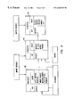
- FIG. 5 shows a flowchart 250 that describes a method for generating an outage notification for monitored service process.
- flowchart 250 can be entered at three different steps, 252 , 254 and 256 , depending on one of three pre-determined events.
- Step 252 is entered when a CPU down system message is read by the monitor function as indicated by condition 258 .
- step 264 is performed by every processor, or CPU, in the network.
- Each CPU in the network determines whether an importer process resides within that CPU's computer system where the importer receives messages from an exporter in the downed CPU. If so, every instrument monitored by the exporter in the downed CPU that communicates with the importer in the current CPU has its monitoring deleted.
- the importer is notified of the exporter outage and the routine of FIG. 5 is exited at step 268 .
- Step 254 is entered periodically when a timer “wake up” occurs.
- Step 260 is entered at each of these timer wake up intervals. For each CPU in the system, all of the exporters in a given CPU are scanned to try to detect an exporter process that is terminated for any reason. If such a terminated exporter is discovered, an outage report is sent to any importer associated with the terminated exporter. As before, step 266 is executed to disable the associated importers and the routine is exited at step 268 .
- routine of flowchart 250 can be entered at step 256 for the condition indicated at step 262 which is when a primary exporter passes control to a backup exporter during a coordinated take over.
- the exporter causes an outage report to be sent to the importer.
- Step 266 indicates that such a message is sent to the importer to disable the importer and the routine is exited at step 268 .
- FIG. 6 shows two flowcharts, flowchart 300 and flowchart 310 , that relate to methods for maintaining the integrity of the monitoring function during component failures.
Abstract
Description
Claims (1)
Priority Applications (5)
| Application Number | Priority Date | Filing Date | Title |
|---|---|---|---|
| US08/377,390 US6360338B1 (en) | 1995-01-24 | 1995-01-24 | Enhanced instrumentation software in fault tolerant systems |
| PCT/US1996/000570 WO1996023257A1 (en) | 1995-01-24 | 1996-01-11 | Enhanced instrumentation software in fault tolerant systems |
| JP8522909A JPH11504141A (en) | 1995-01-24 | 1996-01-11 | Enhanced instrumentation software for fault-tolerant systems |
| EP96903507A EP0806009A4 (en) | 1995-01-24 | 1996-01-11 | Enhanced instrumentation software in fault tolerant systems |
| CA002210494A CA2210494A1 (en) | 1995-01-24 | 1996-01-11 | Enhanced instrumentation software in fault tolerant systems |
Applications Claiming Priority (1)
| Application Number | Priority Date | Filing Date | Title |
|---|---|---|---|
| US08/377,390 US6360338B1 (en) | 1995-01-24 | 1995-01-24 | Enhanced instrumentation software in fault tolerant systems |
Publications (1)
| Publication Number | Publication Date |
|---|---|
| US6360338B1 true US6360338B1 (en) | 2002-03-19 |
Family
ID=23488931
Family Applications (1)
| Application Number | Title | Priority Date | Filing Date |
|---|---|---|---|
| US08/377,390 Expired - Fee Related US6360338B1 (en) | 1995-01-24 | 1995-01-24 | Enhanced instrumentation software in fault tolerant systems |
Country Status (5)
| Country | Link |
|---|---|
| US (1) | US6360338B1 (en) |
| EP (1) | EP0806009A4 (en) |
| JP (1) | JPH11504141A (en) |
| CA (1) | CA2210494A1 (en) |
| WO (1) | WO1996023257A1 (en) |
Cited By (6)
| Publication number | Priority date | Publication date | Assignee | Title |
|---|---|---|---|---|
| US20030033409A1 (en) * | 2001-08-10 | 2003-02-13 | King James E. | Secure network indentity allocation |
| US20060259726A1 (en) * | 2005-05-16 | 2006-11-16 | Texas Instruments Incorporated | Systems and methods for secure debugging and profiling of a computer system |
| US7200651B1 (en) * | 1999-07-02 | 2007-04-03 | Cisco Technology, Inc. | Dynamic configuration and up-dating of integrated distributed applications |
| US20070176246A1 (en) * | 2006-01-31 | 2007-08-02 | Advanced Micro Devices, Inc. | SRAM cells including self-stabilizing transistor structures |
| US20090026521A1 (en) * | 2004-07-30 | 2009-01-29 | Frank Wirbeleit | Self-biasing transistor structure and an sram cell having less than six transistors |
| US20110080772A1 (en) * | 2008-01-31 | 2011-04-07 | Globalfoundries Inc. | Body Controlled Double Channel Transistor and Circuits Comprising the Same |
Families Citing this family (8)
| Publication number | Priority date | Publication date | Assignee | Title |
|---|---|---|---|---|
| US6744894B1 (en) | 1994-04-01 | 2004-06-01 | Mitsubishi Corporation | Data management system |
| US6741991B2 (en) | 1994-09-30 | 2004-05-25 | Mitsubishi Corporation | Data management system |
| EP0715241B1 (en) | 1994-10-27 | 2004-01-14 | Mitsubishi Corporation | Apparatus for data copyright management system |
| US6789197B1 (en) | 1994-10-27 | 2004-09-07 | Mitsubishi Corporation | Apparatus for data copyright management system |
| US6424715B1 (en) | 1994-10-27 | 2002-07-23 | Mitsubishi Corporation | Digital content management system and apparatus |
| EP0709760B1 (en) | 1994-10-27 | 2006-05-31 | Intarsia Software LLC | Data copyright management system |
| JPH10326287A (en) * | 1997-05-23 | 1998-12-08 | Mitsubishi Corp | System and device for digital content management |
| JP2005512190A (en) | 2001-11-30 | 2005-04-28 | オラクル・インターナショナル・コーポレイション | Real composite objects that provide high availability of resources in networked systems |
Citations (2)
| Publication number | Priority date | Publication date | Assignee | Title |
|---|---|---|---|---|
| US5095421A (en) * | 1989-08-17 | 1992-03-10 | International Business Machines Corporation | Transaction processing facility within an operating system environment |
| US5440726A (en) * | 1994-06-22 | 1995-08-08 | At&T Corp. | Progressive retry method and apparatus having reusable software modules for software failure recovery in multi-process message-passing applications |
-
1995
- 1995-01-24 US US08/377,390 patent/US6360338B1/en not_active Expired - Fee Related
-
1996
- 1996-01-11 EP EP96903507A patent/EP0806009A4/en not_active Withdrawn
- 1996-01-11 CA CA002210494A patent/CA2210494A1/en not_active Abandoned
- 1996-01-11 WO PCT/US1996/000570 patent/WO1996023257A1/en not_active Application Discontinuation
- 1996-01-11 JP JP8522909A patent/JPH11504141A/en active Pending
Patent Citations (2)
| Publication number | Priority date | Publication date | Assignee | Title |
|---|---|---|---|---|
| US5095421A (en) * | 1989-08-17 | 1992-03-10 | International Business Machines Corporation | Transaction processing facility within an operating system environment |
| US5440726A (en) * | 1994-06-22 | 1995-08-08 | At&T Corp. | Progressive retry method and apparatus having reusable software modules for software failure recovery in multi-process message-passing applications |
Cited By (19)
| Publication number | Priority date | Publication date | Assignee | Title |
|---|---|---|---|---|
| US7200651B1 (en) * | 1999-07-02 | 2007-04-03 | Cisco Technology, Inc. | Dynamic configuration and up-dating of integrated distributed applications |
| US6952659B2 (en) | 2001-08-10 | 2005-10-04 | Sun Microsystems, Inc. | Computer system monitoring |
| US20030051166A1 (en) * | 2001-08-10 | 2003-03-13 | Garnett Paul J. | Privacy |
| US20030033361A1 (en) * | 2001-08-10 | 2003-02-13 | Garnett Paul J. | Computer system console access |
| US7225235B2 (en) * | 2001-08-10 | 2007-05-29 | Sun Microsystems, Inc. | Computer system console access |
| US20030051057A1 (en) * | 2001-08-10 | 2003-03-13 | Garnett Paul J. | Edge protection |
| US20030105859A1 (en) * | 2001-08-10 | 2003-06-05 | Garnett Paul J. | Intrusion detection |
| US6944019B2 (en) | 2001-08-10 | 2005-09-13 | Sun Microsystems, Inc. | Integrity monitoring |
| US20030033409A1 (en) * | 2001-08-10 | 2003-02-13 | King James E. | Secure network indentity allocation |
| US20080025292A1 (en) * | 2001-08-10 | 2008-01-31 | King James E | Secure network identity allocation |
| US20030051168A1 (en) * | 2001-08-10 | 2003-03-13 | King James E. | Virus detection |
| US20030048615A1 (en) * | 2001-08-10 | 2003-03-13 | King James E. | Integrity monitoring |
| US7299495B2 (en) | 2001-08-10 | 2007-11-20 | Sun Microsystems, Inc. | Virus detection |
| US20090026521A1 (en) * | 2004-07-30 | 2009-01-29 | Frank Wirbeleit | Self-biasing transistor structure and an sram cell having less than six transistors |
| US7774758B2 (en) * | 2005-05-16 | 2010-08-10 | Texas Instruments Incorporated | Systems and methods for secure debugging and profiling of a computer system |
| US20060259726A1 (en) * | 2005-05-16 | 2006-11-16 | Texas Instruments Incorporated | Systems and methods for secure debugging and profiling of a computer system |
| US20070176246A1 (en) * | 2006-01-31 | 2007-08-02 | Advanced Micro Devices, Inc. | SRAM cells including self-stabilizing transistor structures |
| US8507953B2 (en) | 2008-01-31 | 2013-08-13 | Globalfoundries Inc. | Body controlled double channel transistor and circuits comprising the same |
| US20110080772A1 (en) * | 2008-01-31 | 2011-04-07 | Globalfoundries Inc. | Body Controlled Double Channel Transistor and Circuits Comprising the Same |
Also Published As
| Publication number | Publication date |
|---|---|
| WO1996023257A1 (en) | 1996-08-01 |
| JPH11504141A (en) | 1999-04-06 |
| EP0806009A1 (en) | 1997-11-12 |
| EP0806009A4 (en) | 1999-11-24 |
| CA2210494A1 (en) | 1996-08-01 |
Similar Documents
| Publication | Publication Date | Title |
|---|---|---|
| US6353898B1 (en) | Resource management in a clustered computer system | |
| US5193178A (en) | Self-testing probe system to reveal software errors | |
| Bartlett et al. | Fault tolerance in tandem computer systems | |
| US7577731B2 (en) | System and method for monitoring program code | |
| US6092213A (en) | Fault tolerant method of maintaining and distributing configuration information in a distributed processing system | |
| US6360338B1 (en) | Enhanced instrumentation software in fault tolerant systems | |
| EP1679602B1 (en) | Shared memory based monitoring for application servers | |
| US6308284B1 (en) | Method and apparatus for maintaining data coherency | |
| US6490690B1 (en) | Method and apparatus for unix system catastrophic recovery aid | |
| US6910098B2 (en) | Method and apparatus for maintaining data coherency | |
| EP1099164B1 (en) | Method and program for processing administrative requests of a distributed network application executing in a clustered computing environment | |
| Kim | Highly available systems for database applications | |
| US7899897B2 (en) | System and program for dual agent processes and dual active server processes | |
| US8166152B1 (en) | Architecture and method for monitoring system resources within an enterprise network | |
| WO1998019239A1 (en) | Distributed virtual software interface or machine | |
| JP2002543494A (en) | Method and system for handling errors in a distributed computer system | |
| Ferreira et al. | Towards Intra-Datacentre High-Availability in CloudDBAppliance. | |
| Gray et al. | Fault tolerance in Tandem computer systems | |
| Deconinck et al. | A framework backbone for software fault tolerance in embedded parallel applications | |
| Combs et al. | Distributed System Evaluation | |
| Krogh et al. | Typical Troubles and Solutions | |
| Cardoza et al. | Overview of digital UNIX cluster system architecture | |
| Lee et al. | Measurement and analysis of operating system fault tolerance | |
| Wiger et al. | Sun Fire systems design and configuration guide | |
| D EM | SYSTEMS REVIEW |
Legal Events
| Date | Code | Title | Description |
|---|---|---|---|
| AS | Assignment |
Owner name: TANDEM COMPUTERS INCORPORATED, CALIFORNIA Free format text: ASSIGNMENT OF ASSIGNORS INTEREST;ASSIGNORS:JOHNSON, CHARLES S.;EMLICH, LARRY W.;KOMOSINSKI, PAUL;AND OTHERS;REEL/FRAME:007543/0805;SIGNING DATES FROM 19950530 TO 19950531 |
|
| AS | Assignment |
Owner name: COMPAQ COMPUTER CORPORATION, TEXAS Free format text: CERTIFICATE OF OWNERSHIP AND MERGER;ASSIGNOR:TANDEM COMPUTERS INCORPORATED;REEL/FRAME:011469/0216 Effective date: 19991222 |
|
| CC | Certificate of correction | ||
| AS | Assignment |
Owner name: COMPAQ INFORMATION TECHNOLOGIES GROUP, L.P., TEXAS Free format text: ASSIGNMENT OF ASSIGNORS INTEREST;ASSIGNOR:COMPAQ COMPUTER CORPORATION;REEL/FRAME:016641/0312 Effective date: 20010620 |
|
| AS | Assignment |
Owner name: HEWLETT-PACKARD DEVELOPMENT COMPANY, L.P., TEXAS Free format text: ASSIGNMENT OF ASSIGNORS INTEREST;ASSIGNOR:COMPAQ INFORMATION TECHNOLOGIES GROUP, L.P.;REEL/FRAME:016651/0654 Effective date: 20021001 |
|
| AS | Assignment |
Owner name: HEWLETT-PACKARD DEVELOPMENT COMPANY, L.P., TEXAS Free format text: ASSIGNMENT OF ASSIGNORS INTEREST;ASSIGNOR:COMPAQ INFORMATION TECHNOLOGIES GROUP, L.P.;REEL/FRAME:016662/0916 Effective date: 20021001 |
|
| FPAY | Fee payment |
Year of fee payment: 4 |
|
| REMI | Maintenance fee reminder mailed | ||
| LAPS | Lapse for failure to pay maintenance fees | ||
| STCH | Information on status: patent discontinuation |
Free format text: PATENT EXPIRED DUE TO NONPAYMENT OF MAINTENANCE FEES UNDER 37 CFR 1.362 |
|
| FP | Lapsed due to failure to pay maintenance fee |
Effective date: 20100319 |