US6359882B1 - Method and apparatus for transmitting data - Google Patents
Method and apparatus for transmitting data Download PDFInfo
- Publication number
- US6359882B1 US6359882B1 US08/831,321 US83132197A US6359882B1 US 6359882 B1 US6359882 B1 US 6359882B1 US 83132197 A US83132197 A US 83132197A US 6359882 B1 US6359882 B1 US 6359882B1
- Authority
- US
- United States
- Prior art keywords
- data
- communication link
- switch
- network
- high bandwidth
- Prior art date
- Legal status (The legal status is an assumption and is not a legal conclusion. Google has not performed a legal analysis and makes no representation as to the accuracy of the status listed.)
- Expired - Fee Related
Links
Images


Classifications
-
- H—ELECTRICITY
- H04—ELECTRIC COMMUNICATION TECHNIQUE
- H04L—TRANSMISSION OF DIGITAL INFORMATION, e.g. TELEGRAPHIC COMMUNICATION
- H04L69/00—Network arrangements, protocols or services independent of the application payload and not provided for in the other groups of this subclass
- H04L69/16—Implementation or adaptation of Internet protocol [IP], of transmission control protocol [TCP] or of user datagram protocol [UDP]
-
- H—ELECTRICITY
- H04—ELECTRIC COMMUNICATION TECHNIQUE
- H04L—TRANSMISSION OF DIGITAL INFORMATION, e.g. TELEGRAPHIC COMMUNICATION
- H04L1/00—Arrangements for detecting or preventing errors in the information received
- H04L1/12—Arrangements for detecting or preventing errors in the information received by using return channel
- H04L1/16—Arrangements for detecting or preventing errors in the information received by using return channel in which the return channel carries supervisory signals, e.g. repetition request signals
- H04L1/18—Automatic repetition systems, e.g. Van Duuren systems
- H04L1/1829—Arrangements specially adapted for the receiver end
- H04L1/1854—Scheduling and prioritising arrangements
-
- H—ELECTRICITY
- H04—ELECTRIC COMMUNICATION TECHNIQUE
- H04L—TRANSMISSION OF DIGITAL INFORMATION, e.g. TELEGRAPHIC COMMUNICATION
- H04L1/00—Arrangements for detecting or preventing errors in the information received
- H04L1/12—Arrangements for detecting or preventing errors in the information received by using return channel
- H04L1/16—Arrangements for detecting or preventing errors in the information received by using return channel in which the return channel carries supervisory signals, e.g. repetition request signals
- H04L1/18—Automatic repetition systems, e.g. Van Duuren systems
- H04L1/1867—Arrangements specially adapted for the transmitter end
- H04L1/1874—Buffer management
-
- H—ELECTRICITY
- H04—ELECTRIC COMMUNICATION TECHNIQUE
- H04L—TRANSMISSION OF DIGITAL INFORMATION, e.g. TELEGRAPHIC COMMUNICATION
- H04L47/00—Traffic control in data switching networks
- H04L47/10—Flow control; Congestion control
-
- H—ELECTRICITY
- H04—ELECTRIC COMMUNICATION TECHNIQUE
- H04L—TRANSMISSION OF DIGITAL INFORMATION, e.g. TELEGRAPHIC COMMUNICATION
- H04L47/00—Traffic control in data switching networks
- H04L47/10—Flow control; Congestion control
- H04L47/19—Flow control; Congestion control at layers above the network layer
- H04L47/193—Flow control; Congestion control at layers above the network layer at the transport layer, e.g. TCP related
-
- H—ELECTRICITY
- H04—ELECTRIC COMMUNICATION TECHNIQUE
- H04L—TRANSMISSION OF DIGITAL INFORMATION, e.g. TELEGRAPHIC COMMUNICATION
- H04L47/00—Traffic control in data switching networks
- H04L47/10—Flow control; Congestion control
- H04L47/27—Evaluation or update of window size, e.g. using information derived from acknowledged [ACK] packets
-
- H—ELECTRICITY
- H04—ELECTRIC COMMUNICATION TECHNIQUE
- H04L—TRANSMISSION OF DIGITAL INFORMATION, e.g. TELEGRAPHIC COMMUNICATION
- H04L69/00—Network arrangements, protocols or services independent of the application payload and not provided for in the other groups of this subclass
- H04L69/16—Implementation or adaptation of Internet protocol [IP], of transmission control protocol [TCP] or of user datagram protocol [UDP]
- H04L69/163—In-band adaptation of TCP data exchange; In-band control procedures
-
- H—ELECTRICITY
- H04—ELECTRIC COMMUNICATION TECHNIQUE
- H04L—TRANSMISSION OF DIGITAL INFORMATION, e.g. TELEGRAPHIC COMMUNICATION
- H04L69/00—Network arrangements, protocols or services independent of the application payload and not provided for in the other groups of this subclass
- H04L69/16—Implementation or adaptation of Internet protocol [IP], of transmission control protocol [TCP] or of user datagram protocol [UDP]
- H04L69/165—Combined use of TCP and UDP protocols; selection criteria therefor
-
- H—ELECTRICITY
- H04—ELECTRIC COMMUNICATION TECHNIQUE
- H04W—WIRELESS COMMUNICATION NETWORKS
- H04W28/00—Network traffic management; Network resource management
- H04W28/02—Traffic management, e.g. flow control or congestion control
- H04W28/10—Flow control between communication endpoints
-
- H—ELECTRICITY
- H04—ELECTRIC COMMUNICATION TECHNIQUE
- H04W—WIRELESS COMMUNICATION NETWORKS
- H04W8/00—Network data management
- H04W8/02—Processing of mobility data, e.g. registration information at HLR [Home Location Register] or VLR [Visitor Location Register]; Transfer of mobility data, e.g. between HLR, VLR or external networks
- H04W8/04—Registration at HLR or HSS [Home Subscriber Server]
Definitions
- the present invention relates to the field of data communication systems.
- the present invention relates to a system for transmitting data between a source and a destination.
- the costs associated with installing cable-based communication links is prohibitive. For example, in remote areas without any type of existing communication system, it may be too expensive to install cable-based communication links. If additional transmission capacity is needed on existing cable-based communication links, it may be too expensive to install additional cables across oceans, mountains, and other geographic obstacles. Additionally, in locations requiring communication links on a temporary basis, it may not be feasible to install cable-based communication links for the temporary requirements.
- wire-based or cable-based communication links encounter problems with a variety of obstacles, including land rights, river crossings, mountainous terrain, lakes, and oceans. Even without geographic obstacles, remote areas or areas separated by a significant distance may not be serviced economically using wire-based or cable-based communication links. Therefore, solutions must be developed to overcome these obstacles and permit communication links having the necessary bandwidth for communicating data between two locations.
- Satellite transmission systems and other wireless systems provide communication links that do not require the installation of wires or cables across geographic obstacles.
- satellite communication links have a high latency due to the significant distances that the data is transmitted. This high latency may cause problems with the flow of data using certain transmission protocols. For example, the flow of Internet Protocol (IP) data is reduced by the source if the source detects significant delays in receiving acknowledgments from the destination. Typically, a significant delay in receiving acknowledgments indicates congestion on the communication link. Therefore, using a high-latency satellite communication link to transmit IP data is likely to cause the data source to reduce the flow of data, even if the communication link is not congested.
- IP Internet Protocol
- asymmetrical communication links may cause problems with the transmission of certain types of data.
- An asymmetrical communication link has a different latency in each direction (e.g., high-latency communication in one direction and low latency communication in the opposite direction).
- an asymmetrical communication link may have different bandwidths or different communication rates in opposite directions. This asymmetry can cause problems with the flow of data using certain transmission protocols. For example, a source of Internet Protocol (IP) data reduces the outgoing flow of IP data if the source detects significant delays in receiving acknowledgments from the destination. Variations in delays in receiving acknowledgments over a low bandwidth incoming link could cause the source to reduce the flow of data over the outgoing link, even though the outgoing link has adequate capacity to handle the data flow.
- IP Internet Protocol
- the present invention provides a mechanism for transmitting data between communication devices.
- Various embodiments of the invention may be used to transmit data across high latency communication links, asymmetrical communication links, and other communication links that typically provide obstacles for transmitting data such as Internet Protocol (IP) data.
- IP Internet Protocol
- embodiments of the invention avoid problems that occur on high-bandwidth communication links when a large amount of data is sent, creating the possibility that the data identifiers will be repeated.
- Specific embodiments of the invention provide mechanisms for generating an acknowledgment signal that causes the data source to believe that data has been received by the destination. These acknowledgment signals may actually be generated prior to receipt of the data at the destination. These early acknowledgment signals prevent the data source from reducing its data rate due to the high latency or asymmetry of the communication link. Additionally, these early acknowledgment signals avoid the problems caused by repeated identifiers on high-bandwidth communication links.
- An embodiment of the invention provides a system for transmitting data over a high latency communication link.
- the system transmits a data packet from a first device to a second device over a low latency communication link.
- the second device acknowledges receipt of the data packet to the first device over the low latency communication link.
- the second device then transmits the data packet over the high latency communication link.
- the high latency communication link may be a satellite communication link.
- the low latency communication link may be a Transmission Control Protocol/Internet Protocol (TCP/IP) communication link.
- TCP/IP Transmission Control Protocol/Internet Protocol
- Particular embodiments of the invention are capable of transmitting data over a high bandwidth communication link or an asymmetrical communication link.
- FIG. 1 illustrates an embodiment of a switch capable of implementing the teachings of the present invention.
- FIG. 2 illustrates a block diagram of an embodiment of an Internet Protocol (IP) switch.
- IP Internet Protocol
- FIGS. 3A and 3B illustrate example configurations of switches used to couple a pair of networks.
- FIG. 4 illustrates an example communication system using a satellite to transmit data between a pair of switches.
- FIGS. 5 and 6 illustrate other example configurations using a satellite to transmit data between a pair of switches.
- FIG. 7 illustrates a pair of switches capable of communicating with one another across a communication link.
- FIG. 8 is a flow diagram illustrating an embodiment of a procedure performed by an IP input module.
- FIG. 9 is a flow diagram illustrating an embodiment of a procedure performed by a TCP/IP input module.
- FIG. 10 is a flow diagram illustrating an embodiment of a procedure performed by a TCP buffer.
- FIG. 11 is a flow diagram illustrating an embodiment of a procedure performed by an IP switch matrix.
- FIG. 12 is a flow diagram illustrating an embodiment of a procedure performed by a TCP/IP output module.
- FIG. 13 is a flow diagram illustrating an embodiment of a procedure for transmitting data between a pair of switches using a satellite communication link.
- FIG. 14 is a flow diagram illustrating another embodiment of a procedure for transmitting data between a pair of switches using a satellite communication link.
- FIG. 15 illustrates an example MPEG video data stream over a period of time.
- FIGS. 16A and 16B illustrate example MPEG video data streams.
- FIG. 17 is a flow diagram illustrating an embodiment of a procedure for interleaving additional data into a video data stream.
- FIG. 18 is a flow diagram illustrating an embodiment of a procedure for retrieving additional data from a video data stream.
- FIG. 19 illustrates an embodiment of a system capable of interleaving and retrieving additional data from a video data stream.
- FIG. 20 illustrates an embodiment of a computer-readable medium containing various sets of instructions, code sequences, configuration information, and other data.
- TCP/IP Transmission Control Protocol/Internet Protocol
- teachings of the present invention may also be utilized with other transmission protocols.
- various embodiments of the invention will be described, for example, as using a network switching device.
- the present invention may be used with any type of communication device, including switches, routers, servers, embedded controllers, computing devices executing routing or switching algorithms, and other network communication devices.
- Embodiments of the present invention provide a mechanism for transmitting data between communication devices.
- Various embodiments of the invention may be used to transmit data across high latency communication links, asymmetrical communication links, and other communication links that typically provide obstacles for transmitting data such as Internet Protocol (IP) data.
- IP Internet Protocol
- embodiments of the invention avoid problems that occur on high-bandwidth communication links when a large amount of data is sent, creating the possibility that the data identifiers will be repeated.
- Specific embodiments of the invention provide mechanisms for generating an acknowledgment signal that causes the data source to believe that data has been received by the destination. These acknowledgment signals may actually be generated prior to receipt of the data at the destination. These early acknowledgment signals prevent the data source from reducing its data rate due to the high latency or asymmetry of the communication link. Additionally, these early acknowledgment signals avoid the problems caused by repeated identifiers on high-bandwidth communication links.
- FIG. 1 illustrates an embodiment of a switch 10 capable of implementing the teachings of the present invention.
- Switch 10 may be any type of data switching device, such as an IP switch or an Asynchronous Transfer Mode (ATM) switch.
- Switch 10 may handle various types of data, including IP data.
- Switch 10 includes an interface manager 12 capable of controlling interface circuits that receive data on one or more communication links 14 and transmit data on one or more communication links 16 .
- the various communication links 14 and 16 may be coupled to switches, networks, computers, or other devices capable of transmitting or receiving data.
- a switch controller 18 is coupled to interface manager 12 and controls the overall operation of switch 10 .
- switch controller 18 determines when to establish a particular data flow and establishes the data flow in a switch matrix 20 .
- Switch matrix 20 is coupled to switch controller 18 and interface manager 12 , and provides various switching functions for handling the flow of data through switch 10 .
- a protocol manager 22 is coupled to switch controller 18 and switch matrix 20 .
- Protocol manager 22 provides the processing and control functions necessary to implement one or more data transmission protocols, based on the configuration of switch 10 .
- switch matrix 20 performs Internet Protocol (IP) switching
- protocol manager 22 performs Transmission Control Protocol (TCP) management functions.
- IP Internet Protocol
- TCP Transmission Control Protocol
- FIG. 2 illustrates a block diagram of an embodiment of an IP switch 30 .
- IP switch 30 includes an IP input module 32 coupled to receive data on a communication link 34 .
- a TCP/IP input module 36 is coupled to receive data from IP input module 32 .
- IP switch matrix 38 is coupled to receive data from TCP/IP input module 36 and a TCP buffer 40 .
- TCP buffer 40 provides a temporary storage mechanism for data received by TCP/IP input module 36 and awaiting transmission by IP switch matrix 38 or awaiting receipt of an acknowledgment signal from the destination associated with the stored data.
- An interface manager 42 is coupled to IP switch matrix 38 and one or more interface cards 41 .
- Interface manager 42 controls the flow of data through the inputs and outputs of IP switch 30 .
- Various types of interface cards 41 may be provided in IP switch 30 , such as cards to support Frame Relay, ATM, MPEG (Motion Picture Expert Group), Ethernet, and other interfaces.
- a TCP/IP output module 44 is coupled to IP switch matrix 38 and generates the various data packets to be transmitted by IP switch 30 .
- An IP output module 46 is coupled to TCP/IP output module 44 and transmits data packets received from TCP/IP output module 44 across communication link 48 .
- Various other components or modules may be included in particular embodiments of switch 30 .
- FIG. 3A illustrates an example configuration of a pair of switches 50 and 52 used to communicate data between networks 56 and 64 .
- Switches 50 and 52 are coupled together using a communication link 54 .
- communication link 54 is illustrated as a bidirectional communication link.
- switches 50 and 52 may be coupled together using two separate unidirectional communication links.
- Communication link 54 may utilize any type of communication medium to transmit data between switches 50 and 52 . These communication mediums include any type of wire or cable (including fiber optic cable), radio-frequency transmissions, microwave transmissions, and satellite transmissions.
- Switch 50 is coupled to network 56 through a communication link 58 .
- Network 56 can be any type of network capable of transmitting data and other information between various nodes and devices coupled to the network.
- Node 60 represents an example node or network device capable of communicating with network 56 using a communication medium 62 .
- Node 60 may be a workstation, server, or other network device. Although a single node 60 is shown coupled to network 56 , those of ordinary skill in the art will appreciate that any number of nodes and other network devices may be coupled to network 56 . Furthermore, multiple networks of various types and configurations may be coupled to switch 50 .
- Switch 52 is coupled to network 64 through a communication link 66 .
- Network 64 may be a network similar to network 56 , or may have a different topology or use a different network protocol.
- Node 68 is coupled to network 64 through a communication link 70 .
- node 68 may be a workstation, server, or other device capable of communicating with network 64 . Additionally, multiple nodes and devices may be coupled to network 64 .
- switches 50 and 52 are capable of transmitting data between networks 56 and 64 , thereby allowing nodes and devices coupled to network 56 to communicate with nodes and devices coupled to network 64 .
- node 60 has data for transmission to node 68
- the data is passed through network 56 to switch 50 .
- Switch 50 determines which of its interfaces should be used to transmit the data to node 68 .
- switch 50 transmits the data over the interface coupled to communication link 54 .
- the data is received from communication link 54 by switch 52 , and is transmitted through network 64 to node 68 . Additional information regarding the specific data handling procedures utilized by switches 50 and 52 is provided below.
- FIG. 3B illustrates another example configuration utilizing multiple switches to provide communication between networks 56 and 64 .
- four switches 71 , 73 , 75 , and 77 are coupled to one another using communication links 72 , 76 , 78 , and 79 .
- the configuration of FIG. 3B distributes the flow of data through multiple switches to reduce congestion caused by bottlenecks (i.e., large amounts of data flowing through a single switch or across a single communication link). Additionally, each switch can be located in a separate physical location.
- switches 71 , 73 , 75 , and 77 can be coupled to unidirectional communication links 78 and 79 such that switches 73 and 75 are outbound switches and switches 71 and 77 are inbound switches.
- the outbound and inbound switches are identified by the unidirectional communication links 78 and 79 .
- communication links 72 and 76 are bidirectional communication links.
- communication links 78 and 79 are satellite communication links.
- switches 73 and 75 are satellite uplink switches and switches 71 and 77 are satellite downlink switches.
- FIG. 3B allows the use of a single outgoing switch that receives data from multiple receiving switches coupled to a common network, such as a local city network.
- the multiple receiving switches can be located at various office sites, homes, schools, and other locations throughout a geographic area (such as a city).
- the multiple receiving switches transmit data to one or more outgoing switches coupled to the communication medium (e.g., communication medium 78 or 79 ).
- An exemplary local city network can include multiple outgoing switches, each coupled to transmit data from the local city network to another network (e.g., using one or more satellite communication links).
- switch 73 determines which of its interfaces should be used to transmit the data to node 68 . Since switch 73 is an outgoing switch, the data can be communicated across communication link 78 to switch 77 . In this example, switch 77 is not coupled directly to network 64 . Therefore, switch 77 first transmits the data to switch 75 , which then transmits the data through network 64 to node 68 .
- data can be transmitted from node 68 to node 60 by transmitting the data through network 64 to switch 75 . Since switch 75 is an outgoing switch, the data is transmitted across communication link 79 to switch 71 . Switch 71 then transmits the received data to switch 73 using communication link 72 , and switch 73 transmits the data through network 56 to node 60 .
- FIG. 3B represents one exemplary configuration of multiple switches capable of being positioned in separate physical locations.
- switches, networks, and communication links may utilize the teachings of the present invention.
- FIG. 4 illustrates an example communication system using a satellite 84 to transmit data between a pair of switches 80 and 82 .
- a satellite communication link is an example of a high-latency communication link. The high latency is caused by the significant distances that a signal must travel to and from the satellite.
- Switch 80 is coupled to a modulator 86 and a decoder 88 .
- Modulator 86 modulates data signals received from switch 80 and transmits the modulated signals to satellite 84 .
- Incoming signals from satellite 84 are received by decoder 88 , which decodes (or demodulates) the incoming signals and generates data signals that are provided to switch 80 .
- a modulator 90 and a decoder 92 are coupled to switch 82 .
- Modulator 90 modulates data signals received from switch 82 and transmits the modulated signals to satellite 84 .
- Decoder 92 receives modulated signals from satellite 84 and decodes (or demodulates) the incoming signals to generate data signals. The data signals are then provided to switch 82 .
- Switch 80 and a node 96 are coupled to communicate with a network 94 in a manner similar to that described above with respect to FIGS. 3A and 3B.
- switch 82 and a node 100 are coupled to communicate with a network 98 in a manner similar to that described above with respect to FIGS. 3A and 3B.
- node 96 can transmit data to node 100 by transmitting the data through network 94 to switch 80 .
- Switch 80 sends the data to modulator 86 , which modulates the data and transmits a modulated signal to satellite 84 .
- Satellite 84 receives the modulated signal and re-transmits the signal to decoder 92 .
- Decoder 92 decodes the received signal and provides a decoded data signal to switch 82 .
- Switch 82 then transmits the data signal across network 98 to node 100 .
- signals can be received in areas that do not otherwise have communication services (e.g., areas not served by telephone lines or other data communication links) due to geographic obstacles such as oceans or mountainous terrain.
- satellite communication links can provide a high-bandwidth supplement to existing low-bandwidth communication links.
- a satellite communication link is an example of a high-latency communication link.
- high latency can also occur in other systems if a signal must travel a significant distance or if the communication link is congested, thereby increasing the time required to transmit the data.
- FIG. 5 illustrates another example configuration using a satellite 106 to transmit data between a pair of switches 102 and 104 .
- a unidirectional satellite communication link is utilized, such that data transmitted from switch 102 to switch 104 is transmitted using satellite 106 .
- data is transmitted from switch 104 to switch 102 using a different communication link 112 .
- the configuration of FIG. 5 represents an asymmetrical link (i.e., a high-bandwidth, high-latency satellite communication link in one direction and a lower bandwidth, low-latency communication link 112 in the opposite direction).
- Data transmission from switch 102 to switch 104 is accomplished by transmitting the data from switch 102 to a modulator 108 .
- Modulator 108 modulates the data and transmits the modulated signal to satellite 106 .
- Satellite 106 re-transmits the modulated signal to a decoder 110 .
- Decoder 110 decodes the signal and transmits a decoded data signal to switch 104 .
- communication link 112 is shown as a bidirectional, but may also be a unidirectional communication link from switch 104 to switch 102 . If link 112 is bidirectional, data transmitted from switch 102 to switch 104 may utilize either the satellite communication link or communication link 112 . However, data transmitted from switch 104 to switch 102 must use communication link 112 , because the satellite communication link is unidirectional.
- Switch 102 is coupled to a network 114 , which is coupled to a node 116 .
- switch 104 is coupled to a network 118 , which is coupled to a node 120 .
- the unidirectional satellite communication link shown in FIG. 5 is less expensive than the bidirectional satellite communication link shown in FIG. 4 because it requires a single modulator and a single decoder.
- the configuration of FIG. 5 is particularly useful in situations where a significant portion of the data is transmitted in one direction. For example, if node 120 regularly requests significant amounts of data from nodes coupled to network 114 , then communication link 112 is used to transmit the relatively small requests for data, and the satellite communication link is used to transmit the larger amounts of requested data. This type of configuration is useful for transmitting Internet data across the satellite communication link in response to requests received on communication link 112 .
- use of a satellite communication link eliminates various obstacles that are faced by cable-based or land-based communication systems.
- FIG. 6 illustrates another example of a configuration using a satellite communication link.
- a switch 122 and a node 126 are coupled to communicate with a network 124 .
- a modulator 128 receives data from switch 122 , modulates the data, and transmits the modulated signal to a satellite 130 .
- Satellite 130 re-transmits the modulated signal to a decoder 132 .
- Decoder 132 decodes the received signal and transmits a decoded data signal to a node 134 .
- FIG. 6 illustrates a second communication link between node 134 and switch 122 using a pair of modems 136 and 138 , a communication medium 140 , and a terminal server 142 .
- Terminal server 142 translates serial data provided by modem 138 into IP data for use by switch 122 .
- node 134 is coupled directly to a decoder 132 , instead of being coupled to a network and switch, as illustrated in FIG. 5 .
- Node 134 may be any type of device capable of receiving a data signal from decoder 132 and providing a data signal to modem 136 .
- modem 136 is illustrated in FIG. 6 as a separate device, alternate embodiments of the invention may incorporate modem 136 into node 134 . Additionally, specific embodiments of the invention may be implemented without terminal server 142 shown in FIG. 6 . In these embodiments, modem 138 is coupled directly to switch 122 .
- node such as a computer workstation or a network server
- the satellite receiving system may be a home satellite receiver of the type typically used to receive and decode direct-broadcast television signals.
- a separate satellite channel can be provided for transmitting data from switch 122 to node 134 .
- node 134 may request data from a device coupled to network 124 by transmitting a request to switch 122 using modems 136 and 138 .
- Switch 122 receives the request and transmits the request to an appropriate node on network 124 .
- the requested data is then transmitted from the appropriate node across network 124 to switch 122 .
- Switch 122 then transmits the requested data to node 134 using the satellite communication link.
- the configuration of FIG. 6 is particularly useful in Internet applications where the user of node 134 generates data requests that are small in relation to the size of the requested data.
- the relatively small data requests can be transmitted quickly, even across a low-bandwidth communication link.
- the data requests are transmitted using relatively inexpensive modems 136 , 138 and communication medium 140 (e.g., a conventional telephone line).
- communication medium 140 may have limited bandwidth, the bandwidth is sufficient to quickly transmit the relatively small data requests to switch 122 .
- the high-bandwidth satellite communication link allows transmission of the requested data from switch 122 to node 134 in a significantly shorter period of time than would be required to transmit the same data over communication medium 140 .
- the end-user may also receive Internet data using the same satellite receiving system.
- the user can receive Internet data across the high-bandwidth satellite communication link without significant additional cost.
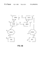
- FIG. 7 illustrates a pair of switches 143 and 144 capable of communicating with one another using communication link 159 .
- the particular switches illustrated in FIG. 7 are IP switches, which are used for purposes of explanation. However, the teachings of the present invention may be applied to other types of switches used for data communication.
- Communication link 159 may be any type of unidirectional or bidirectional link, including a satellite communication link, of the type discussed above with reference to FIGS. 3-6. To simplify the explanation of the operation of switches 143 and 144 , only a portion of each switch is shown.
- switches 143 and 144 are similar to switch 30 described above in FIG. 2 . Links are shown between various modules in each switch 143 , 144 . Some links are shown with arrows for purposes of explanation of signal flows through and between switches 143 , 144 . These arrows do not necessarily identify a unidirectional link. In various embodiments of the invention, any particular link within either switch 143 , 144 can be bidirectional.
- Switch 143 includes an IP input module 147 that receives an input signal from a network source 145 on communication link 146 .
- IP input module 147 transmits the received data to a TCP/IP input module 148 and to an IP switch matrix 154 .
- TCP/IP input module 148 transmits received data to a TCP buffer 150 where the data is stored until an acknowledgment signal is received from the network destination associated with the data. Additionally, TCP/IP input module 148 generates a “false” acknowledgment signal 149 that is transmitted to network source 145 (through IP input module 147 ) indicating that the data was received by the network destination.
- the “false” acknowledgment signal is identical to an actual acknowledgment signal generated by a network destination, but the “false” signal is generated by TCP/IP input module 148 .
- This “false” acknowledgment signal prevents network source 145 from reducing its data transmission rate due to a delayed acknowledgment signal resulting from a high-latency or asymmetrical communication link between switches 143 and 144 .
- network source 145 believes that the data has been received by the network destination when, in fact, the data has been buffered in TCP buffer 150 and is awaiting transmission to the destination.
- a controller 152 controls the operation of IP switch matrix 154 , which switches data to the proper interface using interface manager 156 .
- IP switch matrix 154 uses header information contained in the data packet to switch the data packet to the proper interface.
- Interfaces 158 and 178 in switch 143 are managed by interface manager 156 .
- Output interface 158 is coupled to communication link 159 for communicating with IP switch 144 .
- An interface manager 162 located in switch 144 is coupled to an input interface 160 , which is coupled to communication medium 159 .
- Interface manager 162 provides data received through input interface 160 to an IP switch matrix 164 (using a controller 163 ).
- Controller 163 is also capable of communicating information to interface manager 162 (e.g., a message indicating that IP switch matrix 164 is full). Additionally, controller 163 can send control information to interface manager 162 for transmission to switch 143 through output interface 176 .
- the data received by IP switch matrix 164 is communicated to a TCP/IP output module 166 , which transmits the data to an IP output module 168 .
- IP output module 168 transmits the data across a communication link 170 to a network destination 172 .
- network destination 172 acknowledges receipt of data by returning an acknowledgment signal 174 to switch 144 .
- This acknowledgment signal 174 is illustrated in FIG. 7 as a separate signal having a broken line. Although the acknowledgment signal is illustrated as a separate signal, the actual signal can be transmitted to switch 144 on communication link 170 .
- the acknowledgment signal propagates from IP output module 168 to TCP/IP output module 166 , and continues as shown to interface manager 162 .
- the acknowledgment signal is then transmitted to output interface 176 , and across communication link 159 to input interface 178 in switch 143 .
- the acknowledgment signal is then transmitted to interface manager 156 .
- the acknowledgment signal reaches interface manager 156 , the data acknowledged by the acknowledgment signal is deleted from TCP buffer 150 .
- TCP buffer 150 stores a copy of all data transmitted by switch 143 until an acknowledgment signal is received from the network destination.
- larger fields are used for the sequence numbers transmitted between switches.
- more numbers can be provided to eliminate the possibility of identical active sequence numbers.
- these enlarged sequence number fields may not be supported by other protocols (such as TCP/IP), if each switch on a particular communication link understands the enlarged sequence number field, then the enlarged field will be transparent to the other devices coupled to the switches.
- communication link 54 is a high-latency communication link used to communicate data between switches 50 and 52 . If node 60 has data for transmission to node 68 , node 60 transmits the data across network 56 to switch 50 . Switch 50 then buffers the received data and returns a “false” acknowledgment signal to node 60 , indicating that the data has been received by the destination node (node 68 ). Therefore, node 60 will continue sending the data stream to switch 50 without a reduction in the data rate because node 60 is unaware that communication link 54 is a high latency link.
- Switch 50 then transmits the buffered data to switch 52 while retaining the data in the buffer until the actual acknowledgment is received from node 68 . If the acknowledgment is not received within an expected period of time, the data can be retransmitted from the buffer, without requesting that node 60 retransmit the data to switch 50 . Thus, node 60 is able to transmit data across high-latency communication link 54 without any reduction in the rate of data transmission to switch 50 .
- a switch may transmit multiple copies of the same data packet to the same destination.
- the multiple copies may be spaced apart by a predetermined time period. Transmitting multiple copies of the same data packet increases the likelihood that at least one of the copies will be successfully transmitted to the destination. This is particularly useful in systems having one or more communication links that are susceptible to noise or other distortion that may prevent the successful transmission of a particular data packet. For example, satellite transmission systems may be affected by solar flares.
- the time period between transmitting copies of the same data packet is variable and can be relative to the duration and frequency of the possible noise. In a particular embodiment, the time period is shorter than the time required for the data packet to propagate to the destination.
- long communication links can be more susceptible to noise, and therefore benefit from the transmission of multiple copies of the same data packet.
- Long communication links also require increased time to transmit the data packet and acknowledgment signal, thereby increasing the time that a data source must wait to determine whether a particular packet was successfully transmitted. Transmitting multiple copies of the data packet without waiting for an acknowledgment from the destination is likely to reduce the overall transmission time for a particular data flow.
- communication link 54 in FIG. 3A is an asymmetrical communication link.
- Switch 50 operates in a similar manner by transmitting a “false” acknowledgment signal to node 60 upon receipt of data from node 60 , thereby causing node 60 to continue sending data to switch 50 without reducing the data rate.
- Switch 50 buffers the data and transmits the data across the asymmetrical communication link to switch 52 .
- an actual acknowledgment signal is received by switch 50 , the data is removed from the buffer.
- node 60 is able to transmit data across the asymmetrical communication link without any reduction in the rate of data transmission to switch 50 .
- communication link 54 in FIG. 3A is a high-bandwidth communication link.
- problems may occur in existing systems having high-bandwidth communication links if identical data identifiers (e.g., sequence numbers) are active at the same time.
- switch 50 transmits a “false” acknowledgment signal to node 60 upon receipt of data from node 60 , the problem of identical data identifiers is eliminated.
- node 60 is able to transmit data across the high-bandwidth communication link without the possibility that identical data identifiers will be generated.
- FIGS. 3B, 4 , 5 , and 6 can be used with high-latency communication links, asymmetrical communication links, and high-bandwidth communication links in the manner discussed above with respect to FIGS. 3A and 7.
- FIGS. 8-12 illustrate embodiments of procedures performed by various modules within a switch, such as switch 143 or 144 shown in FIG. 7 . Although the procedures illustrated in FIGS. 8-12 will be described with reference to IP switches, it will be appreciated that similar procedures may be used with different types of switches.
- FIG. 8 is a flow diagram illustrating an embodiment of a procedure performed by an IP input module, such as module 147 shown in FIG. 7 .
- an IP data packet is received from a network source, for example network source 145 .
- Step 182 determines whether the input buffer (e.g., TCP buffer 150 ) for the switch is at a “high water mark.” The high water mark may also be referred to as the “buffer limit” or the “buffer capacity.” If the input buffer has reached its high water mark, then the procedure branches to step 184 where the received packet is discarded and an IP source quench is generated.
- the input buffer e.g., TCP buffer 150
- the IP source quench indicates to the network source that the input buffer is full, and instructs the network source to stop its transmission of data to the switch or reduce the rate at which the data is transmitted to the switch. This request for a reduction in the data transmission rate may also be referred to as a request to “back off.” After discarding the received packet and generating an IP source quench at step 184 , the procedure returns to step 180 to await receipt of the next IP data packet from the network source.
- step 182 of FIG. 8 determines that the input buffer is not at its high water mark, then the procedure continues to step 186 where the received packet is provided to the IP switch matrix. At step 188 , the received packet is sent to the TCP/IP input module. The procedure then returns to step 180 to await receipt of the next IP data packet from the network source.
- FIG. 9 is a flow diagram illustrating an embodiment of a procedure performed by a TCP/IP input module, such as module 148 shown in FIG. 7 .
- a TCP/IP input module such as module 148 shown in FIG. 7 .
- an IP data packet is received by the TCP/IP input module from the IP input module.
- Step 192 determines whether the TCP segment is complete. If the TCP segment is not complete, the procedure branches to step 194 to continue building the TCP segment by adding the IP data packet to the TCP segment. The procedure then returns to step 192 to determine whether the TCP segment is complete. IP data packets are repeatedly added to the TCP segment until the segment is complete.
- step 192 If the TCP segment is complete at step 192 , then the procedure continues to step 196 and generates an acknowledgment signal (ACK signal).
- step 198 the procedure determines whether the TCP Window is at the high water mark. The TCP Window high water mark is typically measured as a percentage of the total buffer capacity. If the TCP Window is at the high water mark, then the routine branches to step 200 where processing of the IP data packet is delayed for a predetermined time period. After the delay, step 200 returns to step 198 to repeat the high water mark determination.
- step 202 the procedure continues from step 198 to step 202 where the ACK signal generated in step 196 is transmitted to the network source (i.e., the source of the received IP packet).
- the ACK signal indicates to the network source that the packet was properly received by the network destination.
- An ACK signal is transmitted to the network source in step 202 even though the packet may not have been transmitted from the switch or received by the network destination.
- the network source continues transmitting packets to switch 143 regardless of whether communication link 159 is a high latency link or an asymmetric link.
- the actual ACK signal received from the network destination is not transmitted to the network source since the “false” ACK signal was previously provided to the network destination.
- the TCP segment is stored in a TCP buffer, such as buffer 150 shown in FIG. 7 .
- the procedure returns to step 190 to await receipt of the next IP data packet.
- the TCP segment remains in the buffer until the actual ACK signal is received from the network destination, at which time the segment is removed from the buffer.
- FIG. 10 is a flow diagram illustrating an embodiment of a procedure performed by a TCP buffer, such as buffer 150 shown in FIG. 7 .
- a TCP acknowledgment signal is received from a TCP/IP output module (e.g., module 166 in FIG. 7 ). This acknowledgment signal is generated by the network destination upon receipt of the TCP segment.
- the ACK signal is received by the switch and provided to the TCP buffer.
- the TCP buffer updates its window counters to reflect the fact that the acknowledged (ACKed) segment will be removed from the buffer.
- the window counters maintain the current utilization of the buffer and are used to determine when the buffer approaches or exceeds the high water mark.
- the window counters are updated each time data is added to or removed from the buffer.
- step 212 After updating the window counters at step 212 , the procedure continues to step 214 where the ACKed TCP segment is removed from the buffer, thereby releasing buffer resources for use by other segments. The procedure then returns to step 210 to await receipt of the next ACK signal.
- FIG. 11 is a flow diagram illustrating an embodiment of a procedure performed by an IP switch matrix, such as switch matrix 154 shown in FIG. 7 .
- an IP data packet is received from an IP input module (e.g., module 147 in FIG. 7 ).
- the procedure continues to step 222 where the IP packet is stored to the switch matrix.
- Step 224 determines whether the switch matrix accepted the packet. If the packet is not accepted at step 224 , then the procedure branches to step 226 to create a route for the packet in the switch matrix. The procedure then returns to step 224 to determine whether the packet was accepted by the switch matrix. When the packet is accepted by the switch matrix, the procedure branches from step 224 to step 220 to await receipt of the next IP packet from the IP input module.
- FIG. 12 is a flow diagram illustrating an embodiment of a procedure performed by a TCP/IP output module, such as module 166 shown in FIG. 7 .
- a TCP acknowledgment signal is received from a network destination (e.g., network destination 172 ).
- the procedure continues from step 230 to step 232 , which is an optional step that buffers the acknowledgment signal.
- the buffering performed at step 232 may be used to group together incoming acknowledgment signals before transmitting the signals to the originating switch.
- the originating switch is the switch that transmitted the data packet being acknowledged (e.g., switch 143 ) to the switch receiving the actual acknowledgment. If buffering is not used, the acknowledgment signals are interleaved with other data being transmitted to the originating switch.
- Step 234 transmits the acknowledgment signal to the TCP buffer in the originating switch (e.g., TCP buffer 150 ).
- the procedure illustrated in FIG. 12 is performed for each received acknowledgment signal.
- FIG. 13 illustrates the operation of a particular embodiment of the invention utilizing a satellite communication link to transmit data between a pair of switches, such as switches 80 and 82 shown in FIG. 4 .
- the first switch e.g., switch 80 in FIG. 4
- receives a data packet from a network source e.g., the first switch queues the data packet for uplink (i.e., transmission) to the satellite.
- the first switch determines whether it has already established a communication with the second switch (e.g., switch 82 ). If the first switch is not communicating with the second switch, then step 244 branches to step 246 where the first switch waits for an acknowledgment signal from the second switch. After receiving the acknowledgment signal, step 246 continues to step 252 where the acknowledgment signal is transmitted from the first switch to the network source.
- step 248 the first switch determines whether the second switch is capable of handling the received data packet. The first switch is capable of making this determination because of the previously established communication with the second switch. If the second switch is not capable of handling the data packet, then the procedure branches to step 246 where the first switch waits for an acknowledgment signal from the second switch. The procedure then continues to step 252 where the acknowledgment signal is transmitted from the first switch to the network source.
- step 250 a “false” acknowledgment signal is generated indicating receipt of the data packet by the network destination.
- the procedure then continues to step 252 where the acknowledgment signal is transmitted to the network source.
- a “false” acknowledgment signal is generated by the first switch, regardless of whether the data packet received from the network source has been transmitted to the second switch or the network destination. This quick generation of a “false” acknowledgment signal alleviates problems associated with the time delay in transmitting the data and the actual acknowledgment signal across the satellite communication link.
- FIG. 14 illustrates the operation of an embodiment of the invention utilizing a unidirectional satellite communication link to transmit data between a pair of switches, such as switches 102 and 104 shown in FIG. 5 .
- the first switch e.g., switch 104 of FIG. 5
- the first switch transmits the data request to a second switch (e.g., switch 102 ) using a communication link such as a telephone line.
- the second switch receives the data request at step 258 and retrieves the requested data through a network or other communication mechanism coupled to the second switch.
- the second switch queues the requested data for uplink (transmission) to a satellite.
- the second switch transmits an acknowledgment signal to the source of the requested data.
- the first switch receives the requested data from the satellite downlink.
- the first switch transmits the requested data to the network node requesting the data. The procedure then returns to step 254 to await the next data request.
- additional data such as IP network data
- another data stream such as an MPEG or MPEG-2 video data stream.
- the additional data is interleaved with the data stream prior to transmission of the data stream.
- the data stream may be transmitted, for example, using one of the communication systems illustrated above in FIGS. 3-6. However, it will be appreciated that any type of communication link may be used to transmit the data signals discussed below.
- FIG. 15 illustrates an example MPEG video data stream over a period of time.
- the bandwidth of the MPEG video data stream varies in response to the amount of MPEG data being transmitted. The varying bandwidth results from changes in the transmitted image and the ability of the MPEG compression system to compress the video data.
- transponder capacity 270 exceeds the MPEG video bandwidth by varying degrees.
- An MPEG video data stream 272 is identified as the lower portion of FIG. 15 and the surplus bandwidth, available for transmitting additional data, is identified by reference numeral 274 in the upper portion of FIG. 15 .
- a significant portion of the total transponder capacity is not utilized by the MPEG video data stream. As discussed below, this unused transponder capacity can be used to transmit additional data, such as network data.
- FIGS. 16A and 16B illustrate example MPEG video data streams.
- MPEG video data is arranged into multiple fixed-length data packets.
- FIG. 16A illustrates seven example MPEG packets in a video data stream. The first packet is approximately 50% utilized, and the remainder of the packet is filled with null data.
- MPEG video data packets are transmitted on a regular basis, regardless of whether sufficient video data is present to fill the packet. Any unused portion of the packet is filled with null data to ensure that all packets are of uniform length.
- the second and fifth data packets are filled completely with null data. Thus, a substantial portion of the space available within MPEG data packets is not used to transmit video data, and instead is filled with null data.
- Embodiments of the present invention take advantage of the unused space (i.e., surplus bandwidth) in the MPEG data packets. Instead of filling the unused portion of each packet with null data, the present invention interleaves additional data, such as network data, into the MPEG data packet.
- FIG. 16B illustrates the seven MPEG data packets shown in FIG. 16A, but filled with network data rather than null data. The interleaving of network data into the video data stream does not affect the performance of the MPEG video transmission because the size of the packets transmitted has not changed.
- the only change between the packets illustrated in FIG. 16 A and those of FIG. 16B is the filling of unused packet space with network data rather than null data. Therefore, the amount of data transmitted is unchanged, but useful data is transmitted instead of null data.
- a portion of a packet may be filled with additional data (e.g., packets 1 , 3 , and 7 ) or an entire packet may be filled with additional data (e.g., packets 2 and 5 ), depending on the amount of MPEG data stored in the packet. If a particular packet is filled with MPEG data, then no additional data is added to the packet (e.g., packets 4 and 6 ).
- FIG. 17 illustrates an embodiment of a procedure for interleaving additional data into a video data stream.
- a switch receives additional data from a data source (e.g., a network data source).
- the switch receives a video data stream from a video source.
- the switch interleaves (or incorporates) the additional data into the unused portions of the data packets in the video stream and encodes the video data stream (e.g., using MPEG or MPEG-2 encoding).
- the header of each packet includes information indicating the portion of the packet that contains video data. This information is used by the decoder to determine the end of the video data.
- Step 286 queues the encoded video data stream, including the interleaved additional data, for transmission.
- the switch generates a “false” acknowledgment signal indicating receipt of the additional data by the data destination.
- the switch transmits the “false” acknowledgment signal to the source of the additional data.
- the switch generates the “false” acknowledgment signal before the actual data is transmitted to or received by the data destination.
- This early acknowledgment by the switch eliminates problems associated with transmitting network data over high latency links such as satellite communication links.
- a “false” acknowledgment signal is not used. Instead, the encoded video data stream, including the additional data, is transmitted or queued for transmission. However, an acknowledgment signal is not transmitted to the source of the additional data until the actual acknowledgment signal is received from the data destination.
- FIG. 18 illustrates an embodiment of a procedure for retrieving additional data, such as network data, from a video data stream, such as an MPEG video stream.
- the video data stream is received by a device such as a switching device.
- the received video data stream is decoded at step 293 .
- an MPEG decoder is used to decode the received video data stream.
- the additional data is deinterleaved (or separated) from the video data stream at step 294 .
- the location within the packet at which the video data ends and the additional data begins is indicated by information contained in the header of each packet. The information identifies the point at which the video data ends. Thus, the video data can be properly separated from the additional data, if any, contained in the packet.
- Step 296 packetizes the additional data into multiple data packets representing the additional data.
- the data packets are transmitted to the data destination.
- the procedure then returns to step 292 to continue processing the video data stream.
- an acknowledgment signal may be transmitted back to the source of the video data stream when an acknowledgment signal is received from the data destination.
- FIG. 19 illustrates an embodiment of a system capable of interleaving and retrieving additional data from a video data stream.
- network data is interleaved with video data and transmitted using an MPEG or MPEG-2 format.
- a pair of video encoders/decoders 300 and 302 are coupled to opposite ends of a communication link 304 .
- Video encoders/decoders 300 and 302 are capable of encoding data into a particular format, such as an MPEG or MPEG-2 format, and decoding an encoded data stream.
- a video data system 306 is coupled to video encoder/decoder 300
- a video data system 308 is coupled to video encoder/decoder 302 .
- Video data systems 306 and 308 may generate or store video signals, or receive and display video signals.
- Video encoder/decoder 300 is coupled to a switch 310 , which is coupled to a network 312 .
- video encoder/decoder 300 is capable of communicating video data signals with video data system 306 and communicating network data signals with network 312 (through switch 310 ).
- a switch 314 is coupled to video encoder/decoder 302 and a network 316 .
- video encoder/decoder 302 can communicate video data signals with video data system 308 and communicate network data signals with network 316 (through switch 314 ).
- the system of FIG. 19 may transmit network data from network 312 to network 316 , and transmit video data from video data system 306 to video data system 308 .
- video encoder/decoder 300 receives network data via switch 310 and video data from video data system 306 .
- Video encoder/decoder interleaves the network data and the video data and encodes the resulting data stream using an appropriate format.
- the encoded data is transmitted across communication link 304 to video encoder/decoder 302 , which decodes the encoded data and deinterleaves (separates) the network data from the video data.
- the network data is transmitted to network 316 via switch 314 , and the video data is transmitted to video data system 308 .
- the system of FIG. 19 may transmit network data from network 316 to network 312 , and transmit video data from video data system 308 to video data system 306 .
- FIG. 20 illustrates an embodiment of a computer-readable (or processor-readable) medium containing various sets of instructions, code sequences, configuration information, and other data.
- Computer-readable medium 320 includes an acknowledgment generator 322 capable of generating acknowledgment signals (such as a “false” acknowledgment signal) for transmission from a switch or other network device.
- a data flow manager 324 controls the flow of data through a switch or other communication device.
- Interface management code 326 manages the various interfaces in a switch or other communication device.
- a resource manager 330 controls and allocates resources within the switch.
- Protocol management code 332 manages the various requirements for each supported protocol.
- Switching code 334 controls the switching matrix within the switch.
- a video encoder/decoder 336 is provided in embodiments of the invention that interleave additional data into a video data stream.
- High latency link management code 338 manages the flow of data on high latency communication links.
- Asymmetric link management code 340 controls the flow of data on asymmetric communication links.
- Data interleaving code 342 interleaves additional data into a data stream.
- Data deinterleaving code 344 deinterleaves (or separates) additional data from a data stream.
- FIG. 20 is suitable for use with various types of communication systems and communication devices, including those discussed above.
- the information stored on medium 320 is used to perform various communication and data processing operations.
- Computer-readable medium 320 may be any type of magnetic, optical, or electrical storage medium including a diskette, CD-ROM, memory device, or similar storage medium.
- one or more of the instruction sets, code sequences, and other data shown in FIG. 20 may be omitted from the system. For example, an embodiment that does not interleave additional data into a data stream may not require video encoder/decoder 336 , data interleaving code 342 , and data deinterleaving code 344 .
Abstract
Description
Claims (15)
Priority Applications (1)
| Application Number | Priority Date | Filing Date | Title |
|---|---|---|---|
| US08/831,321 US6359882B1 (en) | 1997-04-01 | 1997-04-01 | Method and apparatus for transmitting data |
Applications Claiming Priority (1)
| Application Number | Priority Date | Filing Date | Title |
|---|---|---|---|
| US08/831,321 US6359882B1 (en) | 1997-04-01 | 1997-04-01 | Method and apparatus for transmitting data |
Publications (1)
| Publication Number | Publication Date |
|---|---|
| US6359882B1 true US6359882B1 (en) | 2002-03-19 |
Family
ID=25258789
Family Applications (1)
| Application Number | Title | Priority Date | Filing Date |
|---|---|---|---|
| US08/831,321 Expired - Fee Related US6359882B1 (en) | 1997-04-01 | 1997-04-01 | Method and apparatus for transmitting data |
Country Status (1)
| Country | Link |
|---|---|
| US (1) | US6359882B1 (en) |
Cited By (51)
| Publication number | Priority date | Publication date | Assignee | Title |
|---|---|---|---|---|
| US20010000457A1 (en) * | 1995-08-16 | 2001-04-26 | Hinderks Larry W. | Method and apparatus for dynamic allocation of transmission bandwidth resources and for transmission of multiple audio signals with a video signal |
| US20010038686A1 (en) * | 1995-04-10 | 2001-11-08 | Larry Hinderks | Method and apparatus for transmitting coded audio signals through a transmission channel with limited bandwidth |
| US20020078164A1 (en) * | 2000-12-13 | 2002-06-20 | Marnetics Ltd. | System and method for data transfer acceleration in a TCP network environment |
| US20020105955A1 (en) * | 1999-04-03 | 2002-08-08 | Roberts Roswell R. | Ethernet digital storage (EDS) card and satellite transmission system including faxing capability |
| US20020177914A1 (en) * | 1995-09-01 | 2002-11-28 | Tim Chase | Audio distribution and production system |
| US20020194364A1 (en) * | 1996-10-09 | 2002-12-19 | Timothy Chase | Aggregate information production and display system |
| US20030012175A1 (en) * | 2000-02-23 | 2003-01-16 | Benoist Sebire | Method for transmitting data in a radio access network |
| US20030058887A1 (en) * | 2001-09-27 | 2003-03-27 | Dworkin David R. | Method and apparatus for ineterleaving DOCSIS data with an MPEG video stream |
| US20030076846A1 (en) * | 2001-10-24 | 2003-04-24 | Patrick Heinz | System and method for an ethernet optical area network |
| US20030110025A1 (en) * | 1991-04-06 | 2003-06-12 | Detlev Wiese | Error concealment in digital transmissions |
| US20030135546A1 (en) * | 2001-12-19 | 2003-07-17 | Fujitsu Limited | Communications system with automatic data delete function and computer program used for the system |
| US20030149715A1 (en) * | 2000-07-24 | 2003-08-07 | Jussi Ruutu | Flow control |
| US6628677B1 (en) * | 1998-02-28 | 2003-09-30 | Sony Corporation | Coding and multiplexing apparatus and method |
| US6633919B1 (en) * | 1999-11-18 | 2003-10-14 | International Business Machines Corporation | Method, system and program product for managing the flow of data between senders and receivers of a computing environment |
| US20030200284A1 (en) * | 2002-04-22 | 2003-10-23 | Alacritech, Inc. | Freeing transmit memory on a network interface device prior to receiving an acknowledgement that transmit data has been received by a remote device |
| US20030210337A1 (en) * | 2002-05-09 | 2003-11-13 | Hall Wallace E. | Wireless digital still image transmitter and control between computer or camera and television |
| US20050005024A1 (en) * | 2002-10-30 | 2005-01-06 | Allen Samuels | Method of determining path maximum transmission unit |
| US20050005154A1 (en) * | 2003-07-03 | 2005-01-06 | Andrew Danforth | Method to block unauthorized access to TFTP server configuration files |
| US20050060426A1 (en) * | 2003-07-29 | 2005-03-17 | Samuels Allen R. | Early generation of acknowledgements for flow control |
| US20050063302A1 (en) * | 2003-07-29 | 2005-03-24 | Samuels Allen R. | Automatic detection and window virtualization for flow control |
| US20050074007A1 (en) * | 2003-07-29 | 2005-04-07 | Samuels Allen R. | Transaction boundary detection for reduction in timeout penalties |
| US6882624B1 (en) * | 1998-04-09 | 2005-04-19 | Nokia Networks Oy | Congestion and overload control in a packet switched network |
| US20050099969A1 (en) * | 1998-04-03 | 2005-05-12 | Roberts Roswell Iii | Satellite receiver/router, system, and method of use |
| US6963575B1 (en) | 2000-06-07 | 2005-11-08 | Yipes Enterprise Services, Inc. | Enhanced data switching/routing for multi-regional IP over fiber network |
| US20060080187A1 (en) * | 1999-12-28 | 2006-04-13 | Sony Corporation | Portable music player and a photographic image commercial transaction system |
| US20070050821A1 (en) * | 1999-12-28 | 2007-03-01 | Sony Corporation | Image commercial transactions system and method, image transfer system and method, image distribution system and method,display device and method |
| US7249193B1 (en) * | 2001-08-28 | 2007-07-24 | Emc Corporation | SRDF assist |
| US20070202800A1 (en) * | 1998-04-03 | 2007-08-30 | Roswell Roberts | Ethernet digital storage (eds) card and satellite transmission system |
| US20070206615A1 (en) * | 2003-07-29 | 2007-09-06 | Robert Plamondon | Systems and methods for stochastic-based quality of service |
| US20070206621A1 (en) * | 2003-07-29 | 2007-09-06 | Robert Plamondon | Systems and methods of using packet boundaries for reduction in timeout prevention |
| US20070206497A1 (en) * | 2003-07-29 | 2007-09-06 | Robert Plamondon | Systems and methods for additional retransmissions of dropped packets |
| US20070239609A1 (en) * | 1998-03-06 | 2007-10-11 | Starguide Digital Networks, Inc. | Method and apparatus for push and pull distribution of multimedia |
| US20070248107A1 (en) * | 2006-04-20 | 2007-10-25 | Sanden Corporation | Connection Adapter for Communication Device |
| US7313593B1 (en) * | 2000-10-24 | 2007-12-25 | International Business Machines Corporation | Method and apparatus for providing full duplex and multipoint IP audio streaming |
| US20080225715A1 (en) * | 2007-03-12 | 2008-09-18 | Robert Plamondon | Systems and methods of providing proxy-based quality of service |
| US7656799B2 (en) | 2003-07-29 | 2010-02-02 | Citrix Systems, Inc. | Flow control system architecture |
| US20100050040A1 (en) * | 2002-10-30 | 2010-02-25 | Samuels Allen R | Tcp selection acknowledgements for communicating delivered and missing data packets |
| US20100118763A1 (en) * | 2008-11-13 | 2010-05-13 | Elektrobit Wireless Communications Oy | Data Transfer |
| US20110138246A1 (en) * | 2009-12-08 | 2011-06-09 | James Gardner | Method and System for Network Latency Virtualization in a Cloud Transport Environment |
| US20120216235A1 (en) * | 1998-08-14 | 2012-08-23 | International Business Machines Corporation | Wireless Information Transfer and Interactive Television System |
| US8259729B2 (en) | 2002-10-30 | 2012-09-04 | Citrix Systems, Inc. | Wavefront detection and disambiguation of acknowledgements |
| US20120226833A1 (en) * | 2009-11-26 | 2012-09-06 | Freescale Semiconductor, Inc. | Integrated circuit and method for reducing violations of a timing costraint |
| US20130208811A1 (en) * | 2007-06-29 | 2013-08-15 | Cisco Technology, Inc. | Expedited splicing of video streams |
| US8554943B1 (en) * | 2006-03-31 | 2013-10-08 | Emc Corporation | Method and system for reducing packet latency in networks with both low latency and high bandwidths requirements |
| US20140146807A1 (en) * | 2010-06-09 | 2014-05-29 | Pravala, Inc. | Transmitting data over a plurality of different networks |
| US9015471B2 (en) | 2000-07-10 | 2015-04-21 | Alterwan, Inc. | Inter-autonomous networking involving multiple service providers |
| WO2016203161A1 (en) * | 2015-06-18 | 2016-12-22 | Orange | Method and device for managing packets in a multi-stream and multi-protocol connection |
| US10404698B1 (en) | 2016-01-15 | 2019-09-03 | F5 Networks, Inc. | Methods for adaptive organization of web application access points in webtops and devices thereof |
| US10834065B1 (en) | 2015-03-31 | 2020-11-10 | F5 Networks, Inc. | Methods for SSL protected NTLM re-authentication and devices thereof |
| US11025445B2 (en) * | 2018-06-08 | 2021-06-01 | Fungible, Inc. | Early acknowledgment for write operations |
| US20220360644A1 (en) * | 2019-07-03 | 2022-11-10 | Telefonaktiebolaget Lm Ericsson (Publ) | Packet Acknowledgment Techniques for Improved Network Traffic Management |
Citations (53)
| Publication number | Priority date | Publication date | Assignee | Title |
|---|---|---|---|---|
| US4781427A (en) * | 1985-09-19 | 1988-11-01 | The Mitre Corporation | Active star centered fiber optic local area network |
| US5008879A (en) | 1988-11-14 | 1991-04-16 | Datapoint Corporation | LAN with interoperative multiple operational capabilities |
| US5050161A (en) | 1989-12-04 | 1991-09-17 | Bell Communications Research, Inc. | Congestion management based on multiple framing strategy |
| US5053947A (en) * | 1989-09-29 | 1991-10-01 | Allegro Microsystems, Inc. | Extended multistation bus system and method |
| US5140583A (en) * | 1989-06-30 | 1992-08-18 | Inmos Limited | Message routing |
| US5163046A (en) | 1989-11-30 | 1992-11-10 | At&T Bell Laboratories | Dynamic window sizing in a data network |
| US5233603A (en) * | 1988-04-21 | 1993-08-03 | Nec Corporation | Packet switch suitable for integrated circuit implementation |
| US5303302A (en) | 1992-06-18 | 1994-04-12 | Digital Equipment Corporation | Network packet receiver with buffer logic for reassembling interleaved data packets |
| US5309437A (en) | 1990-06-29 | 1994-05-03 | Digital Equipment Corporation | Bridge-like internet protocol router |
| US5321696A (en) * | 1990-11-30 | 1994-06-14 | Motorola, Inc. | Broadcasting of packets in an RF system |
| US5341375A (en) * | 1992-11-12 | 1994-08-23 | Motorola, Inc. | Transmission of broadcast packets in an RF system |
| US5388101A (en) | 1992-10-26 | 1995-02-07 | Eon Corporation | Interactive nationwide data service communication system for stationary and mobile battery operated subscriber units |
| US5432784A (en) | 1993-07-26 | 1995-07-11 | Digital Equipment Corporation | Flow control method and apparatus for systems with long distance links |
| US5442637A (en) | 1992-10-15 | 1995-08-15 | At&T Corp. | Reducing the complexities of the transmission control protocol for a high-speed networking environment |
| US5469542A (en) * | 1991-07-22 | 1995-11-21 | International Business Machines Corporation | Serial diagnostic interface bus for multiprocessor systems |
| US5473599A (en) | 1994-04-22 | 1995-12-05 | Cisco Systems, Incorporated | Standby router protocol |
| US5490252A (en) | 1992-09-30 | 1996-02-06 | Bay Networks Group, Inc. | System having central processor for transmitting generic packets to another processor to be altered and transmitting altered packets back to central processor for routing |
| US5519699A (en) | 1993-12-17 | 1996-05-21 | Nec Corporation | Method of protocol termination and a packet data communication system applied the method |
| US5519704A (en) | 1994-04-21 | 1996-05-21 | Cisco Systems, Inc. | Reliable transport protocol for internetwork routing |
| US5519707A (en) | 1992-10-13 | 1996-05-21 | Synoptics Communications, Inc. | Multiplexing of communications services on a virtual service path in an ATM network or the like |
| US5541987A (en) | 1993-01-11 | 1996-07-30 | Nec Corporation | Connection-oriented congestion controller for common channel signaling network |
| US5550579A (en) | 1986-05-14 | 1996-08-27 | Radio Telecom & Technology, Inc. | Two-way cable tv conversion system |
| US5553061A (en) | 1994-06-27 | 1996-09-03 | Loral Fairchild Corporation | Packet processor having service priority and loss priority features |
| US5553241A (en) | 1992-08-28 | 1996-09-03 | Kabushiki Kaisha Toshiba | Connection-oriented communication system with communication path re-establishment mechanism |
| US5555266A (en) | 1993-10-04 | 1996-09-10 | Motorola, Inc. | Method for reducing transmission delays in a packet transmission system |
| US5557604A (en) | 1994-02-04 | 1996-09-17 | Fujitsu Limited | Cell delay absorbing circuit |
| US5560038A (en) | 1994-07-22 | 1996-09-24 | Network Peripherals, Inc. | Apparatus for translating frames of data transferred between heterogeneous local area networks |
| US5559796A (en) | 1995-02-28 | 1996-09-24 | National Semiconductor Corporation | Delay control for frame-based transmission of data |
| US5563884A (en) | 1995-03-27 | 1996-10-08 | Zenith Electronics Corporation | Reducing multiplex jitter in an ATM/MPEG system |
| US5621793A (en) | 1995-05-05 | 1997-04-15 | Rubin, Bednarek & Associates, Inc. | TV set top box using GPS |
| US5640452A (en) | 1995-04-28 | 1997-06-17 | Trimble Navigation Limited | Location-sensitive decryption of an encrypted message |
| US5650993A (en) | 1995-03-20 | 1997-07-22 | Bell Communications Research, Inc. | Drop from front of buffer policy in feedback networks |
| US5659539A (en) | 1995-07-14 | 1997-08-19 | Oracle Corporation | Method and apparatus for frame accurate access of digital audio-visual information |
| US5663990A (en) * | 1994-09-06 | 1997-09-02 | Interdigital Technology Corporation | Wireless telephone distribution system with time and space diversity transmission |
| US5732387A (en) * | 1995-12-04 | 1998-03-24 | Motorola | Method and apparatus for call establishment in a satellite communication system |
| US5745532A (en) * | 1992-03-12 | 1998-04-28 | Ntp Incorporated | System for wireless transmission and receiving of information and method of operation thereof |
| US5777662A (en) | 1996-08-27 | 1998-07-07 | Comsonics, Inc. | Ingress/egress management system |
| US5792768A (en) | 1993-03-30 | 1998-08-11 | Merck, Sharp & Dohme Limited | Antipsychotic benzimidazole derivatives |
| US5799002A (en) | 1996-07-02 | 1998-08-25 | Microsoft Corporation | Adaptive bandwidth throttling for network services |
| US5809321A (en) | 1995-08-16 | 1998-09-15 | Microunity Systems Engineering, Inc. | General purpose, multiple precision parallel operation, programmable media processor |
| US5812930A (en) * | 1996-07-10 | 1998-09-22 | International Business Machines Corp. | Information handling systems with broadband and narrowband communication channels between repository and display systems |
| US5828335A (en) | 1995-11-06 | 1998-10-27 | Martin Marietta Corporation | Spacecraft communication channel power control system |
| US5835487A (en) | 1995-12-08 | 1998-11-10 | Worldspace International Network, Inc. | Satellite direct radio broadcast system |
| US5854793A (en) | 1992-10-26 | 1998-12-29 | Eon Corporation | GPS synchronization of CTS transmitters for an interactive network |
| US5867769A (en) | 1995-08-02 | 1999-02-02 | Fujitsu Limited | Transmission power control apparatus in earth station for satellite communication |
| US5898680A (en) | 1996-11-05 | 1999-04-27 | Worldspace, Inc. | System for providing location-specific data to a user |
| US5903816A (en) | 1996-07-01 | 1999-05-11 | Thomson Consumer Electronics, Inc. | Interactive television system and method for displaying web-like stills with hyperlinks |
| US5912917A (en) * | 1990-10-18 | 1999-06-15 | Engelbrecht; Lloyd | Digital broadcast system |
| US5918156A (en) | 1988-06-17 | 1999-06-29 | Fujitsu Limited | Broadcasting satellite communication system with improved answer signal transmission |
| US5926470A (en) * | 1996-05-22 | 1999-07-20 | Qualcomm Incorporated | Method and apparatus for providing diversity in hard handoff for a CDMA system |
| US5930248A (en) * | 1997-03-04 | 1999-07-27 | Telefonaktiebolaget Lm Ericsson | Radio communication system selectively using multicast with variable offset time |
| US5955988A (en) | 1996-08-14 | 1999-09-21 | Samsung Electronics Co., Ltd. | Graphical user interface for establishing installation location for satellite based television system |
| US5983112A (en) * | 1990-12-06 | 1999-11-09 | Hughes Electronics Corporation | Frequency, time and power level diversity system for digital radio telephony |
-
1997
- 1997-04-01 US US08/831,321 patent/US6359882B1/en not_active Expired - Fee Related
Patent Citations (54)
| Publication number | Priority date | Publication date | Assignee | Title |
|---|---|---|---|---|
| US4781427A (en) * | 1985-09-19 | 1988-11-01 | The Mitre Corporation | Active star centered fiber optic local area network |
| US5550579A (en) | 1986-05-14 | 1996-08-27 | Radio Telecom & Technology, Inc. | Two-way cable tv conversion system |
| US5233603A (en) * | 1988-04-21 | 1993-08-03 | Nec Corporation | Packet switch suitable for integrated circuit implementation |
| US5918156A (en) | 1988-06-17 | 1999-06-29 | Fujitsu Limited | Broadcasting satellite communication system with improved answer signal transmission |
| US5008879A (en) | 1988-11-14 | 1991-04-16 | Datapoint Corporation | LAN with interoperative multiple operational capabilities |
| US5008879B1 (en) | 1988-11-14 | 2000-05-30 | Datapoint Corp | Lan with interoperative multiple operational capabilities |
| US5140583A (en) * | 1989-06-30 | 1992-08-18 | Inmos Limited | Message routing |
| US5053947A (en) * | 1989-09-29 | 1991-10-01 | Allegro Microsystems, Inc. | Extended multistation bus system and method |
| US5163046A (en) | 1989-11-30 | 1992-11-10 | At&T Bell Laboratories | Dynamic window sizing in a data network |
| US5050161A (en) | 1989-12-04 | 1991-09-17 | Bell Communications Research, Inc. | Congestion management based on multiple framing strategy |
| US5309437A (en) | 1990-06-29 | 1994-05-03 | Digital Equipment Corporation | Bridge-like internet protocol router |
| US5912917A (en) * | 1990-10-18 | 1999-06-15 | Engelbrecht; Lloyd | Digital broadcast system |
| US5321696A (en) * | 1990-11-30 | 1994-06-14 | Motorola, Inc. | Broadcasting of packets in an RF system |
| US5983112A (en) * | 1990-12-06 | 1999-11-09 | Hughes Electronics Corporation | Frequency, time and power level diversity system for digital radio telephony |
| US5469542A (en) * | 1991-07-22 | 1995-11-21 | International Business Machines Corporation | Serial diagnostic interface bus for multiprocessor systems |
| US5745532A (en) * | 1992-03-12 | 1998-04-28 | Ntp Incorporated | System for wireless transmission and receiving of information and method of operation thereof |
| US5303302A (en) | 1992-06-18 | 1994-04-12 | Digital Equipment Corporation | Network packet receiver with buffer logic for reassembling interleaved data packets |
| US5553241A (en) | 1992-08-28 | 1996-09-03 | Kabushiki Kaisha Toshiba | Connection-oriented communication system with communication path re-establishment mechanism |
| US5490252A (en) | 1992-09-30 | 1996-02-06 | Bay Networks Group, Inc. | System having central processor for transmitting generic packets to another processor to be altered and transmitting altered packets back to central processor for routing |
| US5519707A (en) | 1992-10-13 | 1996-05-21 | Synoptics Communications, Inc. | Multiplexing of communications services on a virtual service path in an ATM network or the like |
| US5442637A (en) | 1992-10-15 | 1995-08-15 | At&T Corp. | Reducing the complexities of the transmission control protocol for a high-speed networking environment |
| US5388101A (en) | 1992-10-26 | 1995-02-07 | Eon Corporation | Interactive nationwide data service communication system for stationary and mobile battery operated subscriber units |
| US5854793A (en) | 1992-10-26 | 1998-12-29 | Eon Corporation | GPS synchronization of CTS transmitters for an interactive network |
| US5341375A (en) * | 1992-11-12 | 1994-08-23 | Motorola, Inc. | Transmission of broadcast packets in an RF system |
| US5541987A (en) | 1993-01-11 | 1996-07-30 | Nec Corporation | Connection-oriented congestion controller for common channel signaling network |
| US5792768A (en) | 1993-03-30 | 1998-08-11 | Merck, Sharp & Dohme Limited | Antipsychotic benzimidazole derivatives |
| US5432784A (en) | 1993-07-26 | 1995-07-11 | Digital Equipment Corporation | Flow control method and apparatus for systems with long distance links |
| US5555266A (en) | 1993-10-04 | 1996-09-10 | Motorola, Inc. | Method for reducing transmission delays in a packet transmission system |
| US5519699A (en) | 1993-12-17 | 1996-05-21 | Nec Corporation | Method of protocol termination and a packet data communication system applied the method |
| US5557604A (en) | 1994-02-04 | 1996-09-17 | Fujitsu Limited | Cell delay absorbing circuit |
| US5519704A (en) | 1994-04-21 | 1996-05-21 | Cisco Systems, Inc. | Reliable transport protocol for internetwork routing |
| US5473599A (en) | 1994-04-22 | 1995-12-05 | Cisco Systems, Incorporated | Standby router protocol |
| US5553061A (en) | 1994-06-27 | 1996-09-03 | Loral Fairchild Corporation | Packet processor having service priority and loss priority features |
| US5560038A (en) | 1994-07-22 | 1996-09-24 | Network Peripherals, Inc. | Apparatus for translating frames of data transferred between heterogeneous local area networks |
| US5663990A (en) * | 1994-09-06 | 1997-09-02 | Interdigital Technology Corporation | Wireless telephone distribution system with time and space diversity transmission |
| US5559796A (en) | 1995-02-28 | 1996-09-24 | National Semiconductor Corporation | Delay control for frame-based transmission of data |
| US5650993A (en) | 1995-03-20 | 1997-07-22 | Bell Communications Research, Inc. | Drop from front of buffer policy in feedback networks |
| US5563884A (en) | 1995-03-27 | 1996-10-08 | Zenith Electronics Corporation | Reducing multiplex jitter in an ATM/MPEG system |
| US5640452A (en) | 1995-04-28 | 1997-06-17 | Trimble Navigation Limited | Location-sensitive decryption of an encrypted message |
| US5621793A (en) | 1995-05-05 | 1997-04-15 | Rubin, Bednarek & Associates, Inc. | TV set top box using GPS |
| US5659539A (en) | 1995-07-14 | 1997-08-19 | Oracle Corporation | Method and apparatus for frame accurate access of digital audio-visual information |
| US5867769A (en) | 1995-08-02 | 1999-02-02 | Fujitsu Limited | Transmission power control apparatus in earth station for satellite communication |
| US5809321A (en) | 1995-08-16 | 1998-09-15 | Microunity Systems Engineering, Inc. | General purpose, multiple precision parallel operation, programmable media processor |
| US5828335A (en) | 1995-11-06 | 1998-10-27 | Martin Marietta Corporation | Spacecraft communication channel power control system |
| US5732387A (en) * | 1995-12-04 | 1998-03-24 | Motorola | Method and apparatus for call establishment in a satellite communication system |
| US5835487A (en) | 1995-12-08 | 1998-11-10 | Worldspace International Network, Inc. | Satellite direct radio broadcast system |
| US5926470A (en) * | 1996-05-22 | 1999-07-20 | Qualcomm Incorporated | Method and apparatus for providing diversity in hard handoff for a CDMA system |
| US5903816A (en) | 1996-07-01 | 1999-05-11 | Thomson Consumer Electronics, Inc. | Interactive television system and method for displaying web-like stills with hyperlinks |
| US5799002A (en) | 1996-07-02 | 1998-08-25 | Microsoft Corporation | Adaptive bandwidth throttling for network services |
| US5812930A (en) * | 1996-07-10 | 1998-09-22 | International Business Machines Corp. | Information handling systems with broadband and narrowband communication channels between repository and display systems |
| US5955988A (en) | 1996-08-14 | 1999-09-21 | Samsung Electronics Co., Ltd. | Graphical user interface for establishing installation location for satellite based television system |
| US5777662A (en) | 1996-08-27 | 1998-07-07 | Comsonics, Inc. | Ingress/egress management system |
| US5898680A (en) | 1996-11-05 | 1999-04-27 | Worldspace, Inc. | System for providing location-specific data to a user |
| US5930248A (en) * | 1997-03-04 | 1999-07-27 | Telefonaktiebolaget Lm Ericsson | Radio communication system selectively using multicast with variable offset time |
Non-Patent Citations (8)
| Title |
|---|
| Data-Over-Cable Sevice Interface Specifications, Cable Television Laboratories, Inc., 1999. |
| Jeff Weaver, "An Advanced Scheduler for Satellite Applications", KaSTAR Satellite Communications, Jul. 29, 1999. |
| KaSTAR Overview, www.kastar.net/overview.asp, Nov. 19, 1999. |
| Mercury Center, San Jose Mercury News, "Net transmission standard not suited for space, NASA finds", Oct. 4, 1996, www.sjmercury.com/business/compute/nasa1003.htm. |
| Ongoing TCP Research Related to Satellites, Spencer Dawkins et al., Internet Engineering Task Force (Internet Draft), Mark Allman, Editor, Oct. 1999. |
| Satellite Transmission of Internet IP Traffic, Project GigaSpace(TM), NanoSpace Internet Technologies, 1996. |
| Satellite Transmission of Internet IP Traffic, Project GigaSpace™, NanoSpace Internet Technologies, 1996. |
| Transmission Control Protocol, DARPA Internet Program Protocol Specification, Information Sciences Institute, Sep. 1981. |
Cited By (101)
| Publication number | Priority date | Publication date | Assignee | Title |
|---|---|---|---|---|
| US20030110025A1 (en) * | 1991-04-06 | 2003-06-12 | Detlev Wiese | Error concealment in digital transmissions |
| US20030115043A1 (en) * | 1991-04-06 | 2003-06-19 | Detlev Wiese | Error concealment in digital transmissions |
| US20010038686A1 (en) * | 1995-04-10 | 2001-11-08 | Larry Hinderks | Method and apparatus for transmitting coded audio signals through a transmission channel with limited bandwidth |
| US6778649B2 (en) | 1995-04-10 | 2004-08-17 | Starguide Digital Networks, Inc. | Method and apparatus for transmitting coded audio signals through a transmission channel with limited bandwidth |
| US6700958B2 (en) | 1995-04-10 | 2004-03-02 | Starguide Digital Networks, Inc. | Method and apparatus for transmitting coded audio signals through a transmission channel with limited bandwidth |
| US20030016796A1 (en) * | 1995-04-10 | 2003-01-23 | Larry Hinderks | Method and apparatus for transmitting coded audio signals through a transmission channel with limited bandwidth |
| US20010000457A1 (en) * | 1995-08-16 | 2001-04-26 | Hinderks Larry W. | Method and apparatus for dynamic allocation of transmission bandwidth resources and for transmission of multiple audio signals with a video signal |
| US20020177914A1 (en) * | 1995-09-01 | 2002-11-28 | Tim Chase | Audio distribution and production system |
| US20020194364A1 (en) * | 1996-10-09 | 2002-12-19 | Timothy Chase | Aggregate information production and display system |
| US6628677B1 (en) * | 1998-02-28 | 2003-09-30 | Sony Corporation | Coding and multiplexing apparatus and method |
| US20070239609A1 (en) * | 1998-03-06 | 2007-10-11 | Starguide Digital Networks, Inc. | Method and apparatus for push and pull distribution of multimedia |
| US7650620B2 (en) | 1998-03-06 | 2010-01-19 | Laurence A Fish | Method and apparatus for push and pull distribution of multimedia |
| US8284774B2 (en) | 1998-04-03 | 2012-10-09 | Megawave Audio Llc | Ethernet digital storage (EDS) card and satellite transmission system |
| US20070202800A1 (en) * | 1998-04-03 | 2007-08-30 | Roswell Roberts | Ethernet digital storage (eds) card and satellite transmission system |
| US20050099969A1 (en) * | 1998-04-03 | 2005-05-12 | Roberts Roswell Iii | Satellite receiver/router, system, and method of use |
| US8774082B2 (en) | 1998-04-03 | 2014-07-08 | Megawave Audio Llc | Ethernet digital storage (EDS) card and satellite transmission system |
| US7792068B2 (en) | 1998-04-03 | 2010-09-07 | Robert Iii Roswell | Satellite receiver/router, system, and method of use |
| US6882624B1 (en) * | 1998-04-09 | 2005-04-19 | Nokia Networks Oy | Congestion and overload control in a packet switched network |
| US8756643B2 (en) * | 1998-08-14 | 2014-06-17 | International Business Machines Corporation | Wireless information transfer and interactive television system |
| US20120216235A1 (en) * | 1998-08-14 | 2012-08-23 | International Business Machines Corporation | Wireless Information Transfer and Interactive Television System |
| US20020105955A1 (en) * | 1999-04-03 | 2002-08-08 | Roberts Roswell R. | Ethernet digital storage (EDS) card and satellite transmission system including faxing capability |
| US6633919B1 (en) * | 1999-11-18 | 2003-10-14 | International Business Machines Corporation | Method, system and program product for managing the flow of data between senders and receivers of a computing environment |
| US20060080187A1 (en) * | 1999-12-28 | 2006-04-13 | Sony Corporation | Portable music player and a photographic image commercial transaction system |
| US20070192211A1 (en) * | 1999-12-28 | 2007-08-16 | Sony Corporation | Portable music player and photographic image commercial transactions system |
| US20070050821A1 (en) * | 1999-12-28 | 2007-03-01 | Sony Corporation | Image commercial transactions system and method, image transfer system and method, image distribution system and method,display device and method |
| US8271388B2 (en) | 1999-12-28 | 2012-09-18 | Sony Corporation | Image commercial transactions system and method, image transfer system and method, image distribution system and method, display device and method |
| US20030012175A1 (en) * | 2000-02-23 | 2003-01-16 | Benoist Sebire | Method for transmitting data in a radio access network |
| US6963575B1 (en) | 2000-06-07 | 2005-11-08 | Yipes Enterprise Services, Inc. | Enhanced data switching/routing for multi-regional IP over fiber network |
| US9667534B2 (en) | 2000-07-10 | 2017-05-30 | Alterwan, Inc. | VPN usage to create wide area network backbone over the internet |
| US9015471B2 (en) | 2000-07-10 | 2015-04-21 | Alterwan, Inc. | Inter-autonomous networking involving multiple service providers |
| US9525620B2 (en) | 2000-07-10 | 2016-12-20 | Alterwan, Inc. | Private tunnel usage to create wide area network backbone over the internet |
| US9985800B2 (en) | 2000-07-10 | 2018-05-29 | Alterwan, Inc. | VPN usage to create wide area network backbone over the internet |
| US20030149715A1 (en) * | 2000-07-24 | 2003-08-07 | Jussi Ruutu | Flow control |
| US7313593B1 (en) * | 2000-10-24 | 2007-12-25 | International Business Machines Corporation | Method and apparatus for providing full duplex and multipoint IP audio streaming |
| US20020078164A1 (en) * | 2000-12-13 | 2002-06-20 | Marnetics Ltd. | System and method for data transfer acceleration in a TCP network environment |
| US7249193B1 (en) * | 2001-08-28 | 2007-07-24 | Emc Corporation | SRDF assist |
| US20030058887A1 (en) * | 2001-09-27 | 2003-03-27 | Dworkin David R. | Method and apparatus for ineterleaving DOCSIS data with an MPEG video stream |
| US20030076846A1 (en) * | 2001-10-24 | 2003-04-24 | Patrick Heinz | System and method for an ethernet optical area network |
| US20070212069A1 (en) * | 2001-10-24 | 2007-09-13 | Patrick Heinz | System and method for an Ethernet optical area network |
| US7167648B2 (en) | 2001-10-24 | 2007-01-23 | Innovative Fiber Optic Solutions, Llc | System and method for an ethernet optical area network |
| US7415209B2 (en) | 2001-10-24 | 2008-08-19 | Innovative Fiber Optic Solutions, Llc | Method for operating an ethernet optical area network (“EOAN”) over one more metropolitan areas |
| USRE43340E1 (en) * | 2001-10-24 | 2012-05-01 | 511 Technologies, Inc. | Method for operating an ethernet optical area network (“EOAN”) over one or more metropolitan areas |
| US20030135546A1 (en) * | 2001-12-19 | 2003-07-17 | Fujitsu Limited | Communications system with automatic data delete function and computer program used for the system |
| US7552167B2 (en) * | 2001-12-19 | 2009-06-23 | Fujitsu Limited | Communications control method and system with automatic data congestion preventing function |
| US20030200284A1 (en) * | 2002-04-22 | 2003-10-23 | Alacritech, Inc. | Freeing transmit memory on a network interface device prior to receiving an acknowledgement that transmit data has been received by a remote device |
| US7543087B2 (en) * | 2002-04-22 | 2009-06-02 | Alacritech, Inc. | Freeing transmit memory on a network interface device prior to receiving an acknowledgement that transmit data has been received by a remote device |
| US20030210337A1 (en) * | 2002-05-09 | 2003-11-13 | Hall Wallace E. | Wireless digital still image transmitter and control between computer or camera and television |
| US7542471B2 (en) | 2002-10-30 | 2009-06-02 | Citrix Systems, Inc. | Method of determining path maximum transmission unit |
| US20090201828A1 (en) * | 2002-10-30 | 2009-08-13 | Allen Samuels | Method of determining path maximum transmission unit |
| US7969876B2 (en) | 2002-10-30 | 2011-06-28 | Citrix Systems, Inc. | Method of determining path maximum transmission unit |
| US20100050040A1 (en) * | 2002-10-30 | 2010-02-25 | Samuels Allen R | Tcp selection acknowledgements for communicating delivered and missing data packets |
| US8553699B2 (en) | 2002-10-30 | 2013-10-08 | Citrix Systems, Inc. | Wavefront detection and disambiguation of acknowledgements |
| US8411560B2 (en) | 2002-10-30 | 2013-04-02 | Citrix Systems, Inc. | TCP selection acknowledgements for communicating delivered and missing data packets |
| US20050005024A1 (en) * | 2002-10-30 | 2005-01-06 | Allen Samuels | Method of determining path maximum transmission unit |
| US8259729B2 (en) | 2002-10-30 | 2012-09-04 | Citrix Systems, Inc. | Wavefront detection and disambiguation of acknowledgements |
| US9008100B2 (en) | 2002-10-30 | 2015-04-14 | Citrix Systems, Inc. | Wavefront detection and disambiguation of acknowledgments |
| US9496991B2 (en) | 2002-10-30 | 2016-11-15 | Citrix Systems, Inc. | Systems and methods of using packet boundaries for reduction in timeout prevention |
| US7293282B2 (en) | 2003-07-03 | 2007-11-06 | Time Warner Cable, Inc. | Method to block unauthorized access to TFTP server configuration files |
| US20050005154A1 (en) * | 2003-07-03 | 2005-01-06 | Andrew Danforth | Method to block unauthorized access to TFTP server configuration files |
| US7656799B2 (en) | 2003-07-29 | 2010-02-02 | Citrix Systems, Inc. | Flow control system architecture |
| US8310928B2 (en) | 2003-07-29 | 2012-11-13 | Samuels Allen R | Flow control system architecture |
| US20050060426A1 (en) * | 2003-07-29 | 2005-03-17 | Samuels Allen R. | Early generation of acknowledgements for flow control |
| US8233392B2 (en) | 2003-07-29 | 2012-07-31 | Citrix Systems, Inc. | Transaction boundary detection for reduction in timeout penalties |
| US8238241B2 (en) | 2003-07-29 | 2012-08-07 | Citrix Systems, Inc. | Automatic detection and window virtualization for flow control |
| US20100232294A1 (en) * | 2003-07-29 | 2010-09-16 | Samuels Allen R | Early generation of acknowledgements for flow control |
| US20050074007A1 (en) * | 2003-07-29 | 2005-04-07 | Samuels Allen R. | Transaction boundary detection for reduction in timeout penalties |
| US20070206615A1 (en) * | 2003-07-29 | 2007-09-06 | Robert Plamondon | Systems and methods for stochastic-based quality of service |
| US9071543B2 (en) | 2003-07-29 | 2015-06-30 | Citrix Systems, Inc. | Systems and methods for additional retransmissions of dropped packets |
| US8270423B2 (en) | 2003-07-29 | 2012-09-18 | Citrix Systems, Inc. | Systems and methods of using packet boundaries for reduction in timeout prevention |
| US20100103819A1 (en) * | 2003-07-29 | 2010-04-29 | Samuels Allen R | Flow control system architecture |
| US20050063302A1 (en) * | 2003-07-29 | 2005-03-24 | Samuels Allen R. | Automatic detection and window virtualization for flow control |
| US20070206621A1 (en) * | 2003-07-29 | 2007-09-06 | Robert Plamondon | Systems and methods of using packet boundaries for reduction in timeout prevention |
| US20070206497A1 (en) * | 2003-07-29 | 2007-09-06 | Robert Plamondon | Systems and methods for additional retransmissions of dropped packets |
| US8432800B2 (en) | 2003-07-29 | 2013-04-30 | Citrix Systems, Inc. | Systems and methods for stochastic-based quality of service |
| US8437284B2 (en) | 2003-07-29 | 2013-05-07 | Citrix Systems, Inc. | Systems and methods for additional retransmissions of dropped packets |
| US8462630B2 (en) | 2003-07-29 | 2013-06-11 | Citrix Systems, Inc. | Early generation of acknowledgements for flow control |
| US8824490B2 (en) | 2003-07-29 | 2014-09-02 | Citrix Systems, Inc. | Automatic detection and window virtualization for flow control |
| US7698453B2 (en) * | 2003-07-29 | 2010-04-13 | Oribital Data Corporation | Early generation of acknowledgements for flow control |
| US8554943B1 (en) * | 2006-03-31 | 2013-10-08 | Emc Corporation | Method and system for reducing packet latency in networks with both low latency and high bandwidths requirements |
| US20070248107A1 (en) * | 2006-04-20 | 2007-10-25 | Sanden Corporation | Connection Adapter for Communication Device |
| US20080225715A1 (en) * | 2007-03-12 | 2008-09-18 | Robert Plamondon | Systems and methods of providing proxy-based quality of service |
| US7706266B2 (en) | 2007-03-12 | 2010-04-27 | Citrix Systems, Inc. | Systems and methods of providing proxy-based quality of service |
| US8184534B2 (en) | 2007-03-12 | 2012-05-22 | Citrix Systems, Inc. | Systems and methods of providing proxy-based quality of service |
| US20130208811A1 (en) * | 2007-06-29 | 2013-08-15 | Cisco Technology, Inc. | Expedited splicing of video streams |
| US8804679B2 (en) * | 2008-11-13 | 2014-08-12 | Elektrobit Wireless Communications | Method and apparatus for data transfer with signaling |
| US20100118763A1 (en) * | 2008-11-13 | 2010-05-13 | Elektrobit Wireless Communications Oy | Data Transfer |
| WO2010055203A1 (en) * | 2008-11-13 | 2010-05-20 | Elektrobit Wireless Communications Oy | Data transfer |
| US8706928B2 (en) * | 2009-11-26 | 2014-04-22 | Freescale Semiconductor, Inc. | Integrated circuit and method for reducing violations of a timing constraint |
| US20120226833A1 (en) * | 2009-11-26 | 2012-09-06 | Freescale Semiconductor, Inc. | Integrated circuit and method for reducing violations of a timing costraint |
| US20110138246A1 (en) * | 2009-12-08 | 2011-06-09 | James Gardner | Method and System for Network Latency Virtualization in a Cloud Transport Environment |
| US8397138B2 (en) * | 2009-12-08 | 2013-03-12 | At & T Intellectual Property I, Lp | Method and system for network latency virtualization in a cloud transport environment |
| US20140146807A1 (en) * | 2010-06-09 | 2014-05-29 | Pravala, Inc. | Transmitting data over a plurality of different networks |
| US10601962B2 (en) * | 2010-06-09 | 2020-03-24 | Cth Lending Company, Llc | Transmitting data over a plurality of different networks |
| US10834065B1 (en) | 2015-03-31 | 2020-11-10 | F5 Networks, Inc. | Methods for SSL protected NTLM re-authentication and devices thereof |
| FR3037750A1 (en) * | 2015-06-18 | 2016-12-23 | Orange | METHOD AND DEVICE FOR MANAGING PACKETS IN A MULTI-FLOW AND MULTI-PROTOCOL CONNECTION |
| WO2016203161A1 (en) * | 2015-06-18 | 2016-12-22 | Orange | Method and device for managing packets in a multi-stream and multi-protocol connection |
| US10594500B2 (en) | 2015-06-18 | 2020-03-17 | Orange | Method and device for managing packets in a multi-stream and multi-protocol connection |
| US10404698B1 (en) | 2016-01-15 | 2019-09-03 | F5 Networks, Inc. | Methods for adaptive organization of web application access points in webtops and devices thereof |
| US11025445B2 (en) * | 2018-06-08 | 2021-06-01 | Fungible, Inc. | Early acknowledgment for write operations |
| US20210288830A1 (en) * | 2018-06-08 | 2021-09-16 | Fungible, Inc. | Early acknowledgment for write operations |
| US20220360644A1 (en) * | 2019-07-03 | 2022-11-10 | Telefonaktiebolaget Lm Ericsson (Publ) | Packet Acknowledgment Techniques for Improved Network Traffic Management |
Similar Documents
| Publication | Publication Date | Title |
|---|---|---|
| US6359882B1 (en) | Method and apparatus for transmitting data | |
| US6282172B1 (en) | Generating acknowledgement signals in a data communication system | |
| US6574668B1 (en) | Retransmission scheme in wireless computer networks | |
| EP0454364B1 (en) | High speed transport protocol with two windows | |
| Netravali et al. | Design and implementation of a high-speed transport protocol | |
| US6091733A (en) | Communication device using communication protocol including transport layer and communication method using communication protocol including transport layer | |
| CN111740808B (en) | Data transmission method and device | |
| US6654344B1 (en) | Method and system for controlling data flow in an internet over satellite connection | |
| US6529477B1 (en) | Internet over satellite system | |
| US6584083B1 (en) | Internet over satellite method | |
| US6934255B1 (en) | Internet over satellite apparatus | |
| US20110087915A1 (en) | Hybrid reliable streaming protocol for peer-to-peer multicasting | |
| US6460085B1 (en) | Method and system for managing memory in an internet over satellite connection | |
| JP3814678B2 (en) | Internet via satellite | |
| Clausen et al. | Internet over direct broadcast satellites | |
| KR20030020968A (en) | Real-time packetization and retransmission in streaming applications | |
| US8687530B2 (en) | Stateful scheduling with network coding for roadside-to-vehicle communication | |
| US20110261823A1 (en) | Method and system for multiplexing data streaming in audio/video networks | |
| WO2017144643A1 (en) | Retransmission of data in packet networks | |
| KR20000071688A (en) | Method for improved transmission efficiency between data networks and wireless communication systems | |
| EP2445162B1 (en) | Method For Adaptive Streaming | |
| Giambene et al. | Network coding and MPTCP in satellite networks | |
| CN111464880A (en) | Digital movie copy transmission system based on IPv4 and IPv9 hybrid network | |
| Huang et al. | MHTP-a multimedia high-speed transport protocol | |
| Cao et al. | Reliable multicast via satellites |
Legal Events
| Date | Code | Title | Description |
|---|---|---|---|
| AS | Assignment |
Owner name: NANOSPACE, INC., CALIFORNIA Free format text: ASSIGNMENT OF ASSIGNORS INTEREST;ASSIGNORS:ROBLES, RANK R.;KAMINSKI, PETER;REEL/FRAME:008520/0708 Effective date: 19970401 |
|
| AS | Assignment |
Owner name: YIPES COMMUNICATIONS, INC., CALIFORNIA Free format text: CHANGE OF NAME;ASSIGNOR:NANOSPACE, INC.;REEL/FRAME:011297/0891 Effective date: 19991201 |
|
| AS | Assignment |
Owner name: NORWEST VENTURE PARTNERS VII, L.P., CALIFORNIA Free format text: SECURITY AGREEMENT;ASSIGNOR:YIPES COMMUNICATIONS, INC.;REEL/FRAME:012418/0913 Effective date: 20011227 |
|
| AS | Assignment |
Owner name: PHX COMMUNICATIONS, INC., CALIFORNIA Free format text: ASSIGNMENT OF ASSIGNORS INTEREST;ASSIGNORS:YIPES COMMUNICATIONS, INC.;YIPES COMMUNICATIONS GROUP, INC.;YIPES PROPERTIES, INC.;AND OTHERS;REEL/FRAME:012946/0833 Effective date: 20020630 |
|
| FEPP | Fee payment procedure |
Free format text: PAT HOLDER NO LONGER CLAIMS SMALL ENTITY STATUS, ENTITY STATUS SET TO UNDISCOUNTED (ORIGINAL EVENT CODE: STOL); ENTITY STATUS OF PATENT OWNER: LARGE ENTITY |
|
| FPAY | Fee payment |
Year of fee payment: 4 |
|
| REMI | Maintenance fee reminder mailed | ||
| LAPS | Lapse for failure to pay maintenance fees | ||
| STCH | Information on status: patent discontinuation |
Free format text: PATENT EXPIRED DUE TO NONPAYMENT OF MAINTENANCE FEES UNDER 37 CFR 1.362 |
|
| FP | Lapsed due to failure to pay maintenance fee |
Effective date: 20100319 |