US6325221B2 - Merchandising display track device of multiple-piece construction - Google Patents
Merchandising display track device of multiple-piece construction Download PDFInfo
- Publication number
- US6325221B2 US6325221B2 US08/967,381 US96738197A US6325221B2 US 6325221 B2 US6325221 B2 US 6325221B2 US 96738197 A US96738197 A US 96738197A US 6325221 B2 US6325221 B2 US 6325221B2
- Authority
- US
- United States
- Prior art keywords
- side wall
- track
- tongue
- track device
- track base
- Prior art date
- Legal status (The legal status is an assumption and is not a legal conclusion. Google has not performed a legal analysis and makes no representation as to the accuracy of the status listed.)
- Expired - Lifetime
Links
Images


Classifications
-
- A—HUMAN NECESSITIES
- A47—FURNITURE; DOMESTIC ARTICLES OR APPLIANCES; COFFEE MILLS; SPICE MILLS; SUCTION CLEANERS IN GENERAL
- A47F—SPECIAL FURNITURE, FITTINGS, OR ACCESSORIES FOR SHOPS, STOREHOUSES, BARS, RESTAURANTS OR THE LIKE; PAYING COUNTERS
- A47F1/00—Racks for dispensing merchandise; Containers for dispensing merchandise
- A47F1/04—Racks or containers with arrangements for dispensing articles, e.g. by means of gravity or springs
- A47F1/12—Racks or containers with arrangements for dispensing articles, e.g. by means of gravity or springs dispensing from the side of an approximately horizontal stack
Definitions
- This invention relates to a display track device for merchandising articles, and more particularly to a channel-shaped track device of a multiple-piece construction which enables low-cost molding of such devices.
- Channel-shaped track devices have been used in the merchandising of a variety of products.
- the track devices typically, are supported on a support surface such as a shelf in a tilted condition.
- Each device receives articles in a row so that the received articles slide or gravity feed one after another to the front of the respective track as the leading articles in the row are removed from the track.
- two-piece construction devices are disclosed, for example, in U.S. Pat. No. 4,478,337 (Flum); U.S. Pat. No. 4,724,968 (Wombacher); and U.S. Pat. No. 5,240,126 (Foster et al).
- Flum's device includes front and rear separate members arranged in telescoping relationship which may be employed in Jay's track device.
- the Flum patent requires side walls of a hollow, double-wall structure which is not only expensive but also bulky such that it requires substantial dead space between two adjacent tracks.
- the track device of the invention has a special joint for firmly connecting two or more separate lengths of the track device together to create a one continuous track.
- the present invention in one aspect provides a merchandising track device comprising first and second elongate track members formed separately as two discrete structures.
- the first and second members are connected together in an end-to-end, longitudinally adjacent relationship.
- Each member comprises a track base for carrying articles for sliding movement along the respective member, and at least one article-guiding side wall upstanding from the track base of the respective member and extending along the respective member.
- the one side wall of the first member is disposed in general longitudinal alignment with the one side wall of the second member.
- the track device further comprises locking means for interconnecting the one side wall of the first member and the one side wall of the second member to lock the first and second members in position relative to each other.
- the locking means comprises longitudinal retention means for preventing longitudinal displacement of the one side wall of the first member relative to the one side wall of the second member.
- This arrangement allows low-cost application of a variety of designs as well as materials to different parts of the track device. For example, an expensive mold of a complicated structure can be replaced by two or more less expensive, less complicated molds to form the device of the invention. Further, expensive material can be used only for a particular portion of the device where the use of such material is essential.
- the longitudinal retention means comprises an overhang extending rearward from the one side wall of the first member along the upper edge of the one side wall of the second member, and a lug depending from the overhang and received in a cutout formed along the upper edge of the one side wall of the second member.
- the locking means may also include lateral retention means for preventing lateral displacement of the one side wall of the first member relative to the one side wall of the second member.
- the lateral retention means comprises a pair of engaging tabs provided for the first member. The engaging tabs are disposed respectively alongside the opposite side surfaces of the one side wall of the second member, and at least one of the engaging tabs is formed on the lug.
- the present invention in another aspect provides a merchandising track device comprising first and second separately formed, elongate track members.
- the first and second members are connected together in an end-to-end, longitudinally adjacent relationship.
- Each member comprises an article-carrying track base.
- the second member comprises a tongue extending longitudinally from the track base of the second member which tongue defines an end of the second member.
- the first member has an end-opening socket for receiving the tongue so that the track bases of the first and second members are interconnected to form a continuous floor for slidably supporting articles.
- This arrangement also allows economical application of a variety of designs and materials to different parts of the track device.
- the track base of the first member comprises upper and lower opposed walls, and the socket is defined between the upper and lower walls.
- the upper surface of the tongue is disposed below the continuous floor of the device so that the upper surfaces of the track bases may lie in a common plain.
- the tongue may be provided with a downwardly projecting hooking element, and the track base of the first member may have a transversely extending edge for engaging the hooking element to prevent longitudinal displacement of the first member with respect to the second member.
- the present invention in a still another aspect provides a merchandising track device comprising an elongate body, and a front piece formed as a discrete structure and attached to the front end of the body.
- the body comprises a track base for carrying a row of articles for sliding movement along the body, and at least one article-guiding side wall upstanding from the track base and extending along the body.
- the front piece provides a stopper for preventing the leading article in the row from exiting the track device.
- the front piece comprises a deck for supporting the leading article, at least one longitudinally extending upright wall upstanding from the deck and disposed in general longitudinal alignment with the one side wall, and locking means for interconnecting the one upright wall and the one side wall to lock the front piece in position relative to the body.
- the elongate body and the front piece may be molded from either plastic or metal (e.g., aluminum, aluminum compound or the like).
- the body and the front piece may be formed from different material.
- any plastic or metal may be used to construct the device of the invention, the most preferred material for the body is polystyrene whereas the most preferred material for the front piece is polycarbonate.
- a preferred embodiment of the locking means comprises lateral retention means for preventing lateral displacement of the one upright wall relative to the one side wall.
- lateral retention means may be a pair of engaging tabs provided for the one upright wall which engaging tabs are disposed alongside the opposite side surfaces of the one side wall, respectively. These engaging tabs are disposed with a lateral gap therebetween to receive in the gap an edge of the one side wall.
- the engaging tabs may be opposed to each other across the thickness of the one side wall. Alternatively, the engaging tabs may be disposed at positions offset from each other along the length of the one side wall.
- the locking means comprises longitudinal retention means for preventing longitudinal displacement of the one upright wall relative to the one side wall.
- the longitudinal retention means may comprise an overhang extending rearward from the one upright wall along the upper edge of the one side wall, and a lug depending from the overhang. Such a longitudinal retention means cooperates with a cutout formed along the upper edge of the one side wall to receive the lug.
- the aforementioned lateral retention means may also be incorporated into the arrangement with the longitudinal retention means which lateral retention means comprises a pair of engaging tabs provided for the one upright wall.
- lateral retention means comprises a pair of engaging tabs provided for the one upright wall.
- at least one of the engaging tabs is formed on the lug.
- the lug may have a thickness greater than the thickness of the one side wall.
- the other tab may be formed on the one upright wall or on the overhang.
- the present invention in a further aspect provides a merchandising track device comprising an elongate body and an attached front piece.
- the body comprises a track base for supporting a row of articles for sliding movement along the body, and a tongue extending forwardly from the track base and defining the forward end of the body.
- the front piece provide a stopper for the leading article in the row.
- the front piece comprises a deck for supporting the leading article which deck has a socket for receiving the tongue so that the deck and the track base are interconnected to form a continuous floor for slidably supporting the articles.
- the deck comprises upper and lower opposed walls, and the socket is defined between the upper and lower walls.
- the upper surface of the tongue is disposed below the continuous floor so that the upper surface of the deck and the upper surface of the track base may lie in a common plain.
- the tongue may be provided with a downwardly projecting hooking element, and the deck may have a transversely extending edge for engaging the hooking element to prevent forward displacement of the front piece.
- FIG. 1 is a perspective view of a shelf unit assembled from a plurality of track devices according to the present invention
- FIG. 2 is a fragmentary perspective view of one of the track devices in FIG. 1;
- FIG. 3 is an exploded perspective view of the track device in FIG. 2;
- FIG. 4 is a front elevation of the front piece in FIG. 3;
- FIG. 5 is a bottom plan view of the front piece in FIG. 3;
- FIG. 6 is a view taken along the line VI—VI in FIG. 5;
- FIG. 7 is a view similar to FIG. 6 except that the body is connected to the front piece by the insertion of the tongue into the socket;
- FIG. 8 is an enlarged perspective view of the locking means in FIG. 3;
- FIG. 9 is a top plan view of the front piece in FIG. 3;
- FIG. 10 is an enlarged top plan view of the locking means in FIG. 9;
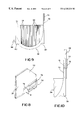
- FIG. 11 is an exploded top plan view of the second embodiment of the present invention.
- FIG. 12 is a front elevation of the joined front pieces in FIG. 11;
- FIG. 13 is a front elevation of the joined bodies in FIG. 11;
- FIG. 14 is an enlarged perspective view of the locking means in FIG. 11 .
- FIG. 1 illustrates a display shelf unit assembled from multiple track devices according to the present invention.
- This shelf unit is designed to merchandise articles C such as bottled or canned drink products.
- the shelf unit includes a plurality of elongate track devices 20 detachably interconnected in a side-by-side, transversely adjacent relationship.
- the number of the track device 20 used to assemble the shelf unit is determined such that the size of the shelf unit is suitable for placement onto an existing display shelf in a retail store in which the unit is desired to be installed.
- the interconnection of two adjacent track devices is achieved by connecting means such as connector slots 80 (shown in FIG. 1) cooperating with L-shaped horizontal connector elements 82 (only one shown in FIG. 2 ). Details of the slots 80 and the elements 82 are described in U.S. Pat. No. 5,634,564 which is hereby incorporated by reference. Additional connecting means are provided at the front portion of each device which additional means will be described later.
- the shelf unit may be supported on a horizontal surface and may preferably be incorporated with a spring-loaded pusher for moving the loaded articles forwardly of the unit.
- a spring-loaded pusher for moving the loaded articles forwardly of the unit.
- An example of conventional pushers is shown in U.S. Pat. No. 5,634,564.
- the shelf unit may also be supported on a forwardly and downwardly tilted surface.
- each track device 20 operates as a so called “gravity feed” dispensing device which does not require any mechanical pushers.
- the loaded articles On a gravity feed device, the loaded articles have a natural tendency to automatically slide downwardly and forwardly to the front end of the track.
- the angle of tilt from the horizontal may vary somewhat but such an angle may be about 1 to 20 degrees and preferably about 3.5 to 8 degrees. The angle of tilt in most applications of the invention may be approximately 6 degrees from horizontal.
- FIGS. 2 and 3 illustrate one of the track devices 20 in the form separated from the shelf unit. As all the devices 20 are virtually the same in size and structure, only one device is described hereinafter.
- the track device 20 has a two-piece construction formed of molded plastic material and includes a first member or front piece 24 and a second member or elongate track body 22 .
- the body 22 includes an article-supporting track base 26 , an article-guiding side wall 28 , a rear wall 30 , and a side lip 32 .
- the side wall 28 is upstanding from one of the side edges of the track base 26 .
- the rear wall 30 is upstanding from the rear end of the track base 26 .
- the side lip 32 is formed along the other side edge of the track base 26 .
- the track base 26 , the side wall 28 and the side wall of the adjacent track body 22 in cooperation, define a channel for receiving a row of articles C.
- the front piece 24 is molded separately from the body 22 to provide a front stopper for preventing the leading article in the row from exiting the track device.
- the front piece 24 includes a track base or deck 34 , a longitudinally extending side wall or upright wall 36 , an upper stopper element 38 , and a pair of lower stopper elements 40 .
- the upright wall 36 is upstanding from one of the opposite side edges of the deck 34 to be disposed in general longitudinal alignment with the side wall 28 .
- the upper stopper element 38 extends transversely of the device 20 to bridge between the respective upper ends of the upright wall 36 and a post 42 which is upstanding from the other side edge of the deck 34 .
- the upper stopper element 38 is the portion against which the leading article on the respective device 20 rests when it is arrested by the front piece 24 . Details of the upper stopper element are described in U.S. Pat. No. 5,645,176 which is hereby incorporated by reference.
- the lower stopper elements 40 extend upwardly from the deck 36 along the respective front edges of the upright wall 36 and the post 42 . These lower stopper elements 40 cooperate with the upper stopper element 38 to arrest the leading article.
- a tongue 44 is formed integrally with the body 22 as shown in FIG. 3 .
- the tongue 44 extends forwardly from the track base 26 and defines the forward end of the body 22 .
- a pair of notches 46 are formed in the tongue 44 to divide the tongue 44 into three portions, i.e., a pair of side portions 48 and a medial portion 50 . Due to the notches 46 , the medial portion 50 exhibits substantial flexibility.
- the medial portion 50 is provided along its transversely extending free end edge with a downwardly projecting hooking rib 52 .
- the upper surface of the tongue 44 is disposed below a common plane in which the tops or peaks of upwardly projecting parallel ribs 54 lie.
- the ribs 54 are formed integrally with the track base 26 along the length of the track device 20 to minimize friction between the track base 26 and the articles to be carried thereon. In other words, the ribs 54 provide a part of the “continuous floor” for slidably supporting articles, which continuous floor lies in the aforesaid common plane. Because the upper surface of the tongue 44 is below the common plane, the deck 34 is allowed to cooperate with the ribs 54 to form the continuous floor when the front piece 24 is attached to the body 22 . This will be described later more specifically.
- the ribs 54 preferably, are arranged at equal spacings and are of a generally trapezoidal cross section.
- the means for cooperating or mating with the tongue 44 is provided for the front piece 24 in the form of a socket 60 that is defined between the upper and lower opposed walls 56 and 58 of the deck 34 (see FIGS. 5 and 6 ).
- the lower wall 58 includes a strip portion 62 extending transversely of the deck 34 .
- This strip portion 62 has a front face which provides a transversely extending engaging edge 64 for engagement with the hooking rib 52 of the tongue 44 .
- the rear face 66 of the strip portion 62 slopes downwardly and rearwardly to facilitate insertion of the tongue 44 into the socket 60 .
- the upper wall 56 of the deck 34 is formed integrally with a plurality of upwardly projecting parallel ribs 68 .
- These ribs 68 are arranged such that they are brought into longitudinal alignment with the ribs 54 of the track base 26 when the front piece 24 is attached to the track body 22 .
- the vertical size of the ribs 68 is substantially less than that of the ribs 54 so that when the body 22 and front piece 24 are interconnected, the tops or peaks of the ribs 68 and those of the ribs 54 can lie in the aforesaid common plane to provide the “continuous floor” for articles.
- the vertical size of the ribs 54 is equal to the total thickness or vertical size of the upper wall 56 and the ribs 68 . This is best shown in FIG. 7 .
- Locking means is provided for the front piece 24 to interconnect the upright wall 36 and the side wall 28 .
- Such locking means comprises an overhang 70 joined to the upright wall 36 and extending rearward along the upper edge of the side wall 28 .
- An engaging lug 72 is formed integrally with the overhang 70 and depends from the overhang 70 to be received in a cutout 74 (shown in FIG. 3) formed in the side wall 28 along its upper edge.
- the thickness or transverse size “T” (shown in FIG. 5) of the lug 72 is greater than that of the side wall 28 .
- a pair of inner and outer engaging tabs 76 and 78 are joined to the lower end of the lug 72 and extend downwardly therefrom. These engaging tabs 76 and 78 are disposed with a lateral gap “G” between themselves to receive in the gap “G” the horizontally extending periphery of the cutout 74 .
- the illustrated engaging tabs 76 and 78 are disposed at positions offset from each other; however, they may be transversely aligned or opposed across the gap “G”.
- keyhole apertures 84 are formed in the upright wall 36 to connect the front piece 24 with the adjacent like front piece.
- headed tabs 86 are formed in the upright wall 36 to connect the front piece 24 with the adjacent like front piece.
- These apertures and tabs 84 and 86 cooperate with the aforementioned slots and elements 80 and 82 to interconnect the track device 20 with an adjacent like track device.
- a variety of conventional mechanisms may be used to secure two adjacent track devices 20 in such a side-to-side, transversely adjacent relationship.
- the above body 22 and the front piece 24 may be molded from either plastic or metal; however, they are preferably formed from a plastic material such as polyvinyl chloride, polystyrene, polycarbonate or the like. Among these plastic materials, the most preferred material for manufacturing the body 22 is high impact polystyrene whereas the most preferred material for manufacturing the front piece 24 is polycarbonate.
- the polystyrene for molding the body 22 may have silicone or some other suitable lubricant material dispersed therein in order to reduce friction between the ribs 54 and the articles to be placed thereon.
- body 22 and the front piece may be formed from the same material. For example, when both the body 22 and the front piece 24 are made of polycarbonate, an entirely transparent track device may be created.
- the front piece 24 may be attached to the body 22 in the following manner:
- the tongue 44 of the body 22 is inserted through the rear end opening (i.e., the entrance of the socket 60 ) of the deck 34 until the lug 72 abuts the front edge of the side wall 28 .
- the overhang 70 is then slightly flexed toward either side of the side wall 28 to prevent the lug 72 from interfering with the side wall 28 .
- Further forward movement of the tongue 44 causes the hooking rib 52 to abut the rear sloping face 66 of the strip portion 62 .
- the hooking rib 52 is caused to slide upwardly along the sloping face 66 while the medial portion 50 is resiliently bent upwardly.
- the hooking rib 52 is thus guided along the surface of the strip portion 62 until the tongue 44 is fully inserted to allow the hooking rib 52 to snap-engage the edge 64 of the strip portion 62 (see FIG. 7 ). This engagement prevents forward displacement or undesired detachment of the deck 34 from the track base 26 .
- the overhang 70 is slightly twisted to manipulate the inner and outer engaging tabs 76 and 78 to receive in the gap “G” the horizontally extending peripheral edge of the cutout 74 .
- the lug 72 snugly fits into the cutout 74 with the inner and outer engaging tabs 76 and 78 being positioned alongside the inside and outside surfaces of the side wall 28 , respectively.
- Such an arrangement of the inner and outer tabs 76 and 78 is best shown in FIG. 10 . This arrangement prevents both forward and lateral displacement of the upright wall 36 with respect to the side wall 28 .
- the track device of the invention may include three or more separately formed, longitudinally adjacent track members, wherein each pair of two adjacent track members are connected together through the locking means and/or the tongue-and-socket joint mentioned above.
- each of the first and second track members 24 and 22 may have a pair of side walls wherein the side walls of the first member 24 are connected respectively to the side walls of the second member 22 through the locking means.
- the present invention may be incorporated into a shelf unit wherein multiple first track members are molded together in a side-by-side, longitudinally adjacent relationship and so are multiple second track members.
- An example of such a variation is illustrated in FIGS. 11-14 wherein a plurality of track bodies 90 are molded together so that the respective track bases 92 are joined together through side walls 94 .
- a plurality of front pieces 96 are also molded together so that the respective decks 98 are joined together and the respective upper stopper elements 100 are joined together in series.
- Each pair of a body 90 and a front piece 96 employs a tongue 102 and a socket virtually equal to the tongue and the socket described in the foregoing embodiment.
- the locking means used in this embodiment is different from the one in the foregoing embodiment.
- the locking means includes an outer engaging tab 104 depending from the lug 106 and an inner engaging tab 108 extending rearward from a ledge 110 that is formed on the inside surface of the respective upright wall 112 .
- the rear end of the ledge 110 is brought into abutment with the forward end of the associated side wall 94 , and the inner tab 108 is located alongside the inside surface of the side wall 94 .
Landscapes
- Display Racks (AREA)
Abstract
Description
Claims (17)
Priority Applications (3)
| Application Number | Priority Date | Filing Date | Title |
|---|---|---|---|
| US08/967,381 US6325221B2 (en) | 1997-11-08 | 1997-11-08 | Merchandising display track device of multiple-piece construction |
| AU13124/99A AU1312499A (en) | 1997-11-08 | 1998-11-06 | Merchandising display track device of multiple-piece construction |
| PCT/US1998/023679 WO1999023918A1 (en) | 1997-11-08 | 1998-11-06 | Merchandising display track device of multiple-piece construction |
Applications Claiming Priority (1)
| Application Number | Priority Date | Filing Date | Title |
|---|---|---|---|
| US08/967,381 US6325221B2 (en) | 1997-11-08 | 1997-11-08 | Merchandising display track device of multiple-piece construction |
Publications (2)
| Publication Number | Publication Date |
|---|---|
| US20010002658A1 US20010002658A1 (en) | 2001-06-07 |
| US6325221B2 true US6325221B2 (en) | 2001-12-04 |
Family
ID=25512713
Family Applications (1)
| Application Number | Title | Priority Date | Filing Date |
|---|---|---|---|
| US08/967,381 Expired - Lifetime US6325221B2 (en) | 1997-11-08 | 1997-11-08 | Merchandising display track device of multiple-piece construction |
Country Status (3)
| Country | Link |
|---|---|
| US (1) | US6325221B2 (en) |
| AU (1) | AU1312499A (en) |
| WO (1) | WO1999023918A1 (en) |
Cited By (62)
| Publication number | Priority date | Publication date | Assignee | Title |
|---|---|---|---|---|
| US6523702B1 (en) * | 2001-10-31 | 2003-02-25 | Display Industries, Llc | Inclined merchandising display track device |
| US6585120B2 (en) * | 1997-10-01 | 2003-07-01 | Display Industries, Llc. | Display shelf having an anti-rotation member |
| US20030132182A1 (en) * | 2002-01-14 | 2003-07-17 | Richard Jay | Depth-extendable display track unit |
| US6615995B2 (en) * | 2001-10-31 | 2003-09-09 | Display Industries, Llc. | Merchandising display track device |
| US6679389B1 (en) * | 2002-07-29 | 2004-01-20 | Display Industries, Llc | Front piece for a merchandising display track device |
| US20040020877A1 (en) * | 2002-08-01 | 2004-02-05 | Paul Flum Ideas, Inc. | Product merchandising display unit with pull through front wall members |
| US6702127B2 (en) | 2002-03-11 | 2004-03-09 | Display Industries, Llc. | Display track device with anti-torsion front cylinder |
| US6722509B1 (en) | 2002-10-31 | 2004-04-20 | Display Industries, Llc. | Display track device with front panels and top stop members |
| US20040084391A1 (en) * | 2002-10-31 | 2004-05-06 | Bernard Primiano | Display track device with anti-torsion bar |
| US6779670B2 (en) | 2001-10-31 | 2004-08-24 | Display Industries, Llc. | Merchandising display track device |
| US20050067362A1 (en) * | 2001-06-08 | 2005-03-31 | Martin Arthur R. | Display system |
| US20050109775A1 (en) * | 2003-10-17 | 2005-05-26 | Meissen Cynthia R. | Shipping unit |
| US6964344B1 (en) * | 2003-09-26 | 2005-11-15 | Kim Chang S | Display tray and rack assembly |
| US20060138065A1 (en) * | 1999-12-08 | 2006-06-29 | Squitieri Anthony C | Glide |
| US20060196840A1 (en) * | 2005-03-01 | 2006-09-07 | Richard Jay | Product dispenser track assembly |
| US20070256992A1 (en) * | 2006-05-04 | 2007-11-08 | Carl Olson | Shelf divider system |
| US20090184069A1 (en) * | 2005-09-12 | 2009-07-23 | Rtc Industries, Inc. | Product Management Display System With Trackless Pusher Mechanism |
| US20090223914A1 (en) * | 2008-03-10 | 2009-09-10 | William Henry Kahl | Theft deterrent can dispenser |
| US7757890B2 (en) | 2005-10-12 | 2010-07-20 | Rtc Industries, Inc. | Cylindrical container dispenser |
| US7823734B2 (en) | 2005-09-12 | 2010-11-02 | Rtc Industries, Inc. | Product management display system with trackless pusher mechanism |
| US20110094980A1 (en) * | 2009-10-23 | 2011-04-28 | Cousin Serge L | Display channel apparatus |
| US20110163113A1 (en) * | 2010-01-06 | 2011-07-07 | Matthew Eric Grubbs | Dispenser for round and rectangular cans |
| US8056734B2 (en) | 2006-10-23 | 2011-11-15 | Rtc Industries, Inc. | Merchandising system with flippable column and/or item stop |
| US8312999B2 (en) | 2005-09-12 | 2012-11-20 | Rtc Industries, Inc. | Product management display system with trackless pusher mechanism |
| US20130031815A1 (en) * | 2005-09-12 | 2013-02-07 | Rtc Industries Inc. | Product Management Display System with Trackless Pusher Mechanism |
| US8739984B2 (en) | 2005-09-12 | 2014-06-03 | Rtc Industries, Inc. | Product management display system with trackless pusher mechanism |
| US20140175032A1 (en) * | 2012-12-20 | 2014-06-26 | Hon Hai Precision Industry Co., Ltd. | Mounting apparatus for goods channel |
| US20140360953A1 (en) * | 2013-06-11 | 2014-12-11 | Display Technologies | Merchandising system with pusher assembly |
| US8967394B2 (en) | 2005-09-12 | 2015-03-03 | Rtc Industries, Inc. | Product management display system with trackless pusher mechanism |
| US8978904B2 (en) | 2005-09-12 | 2015-03-17 | Rtc Industries, Inc. | Product management display system with trackless pusher mechanism |
| US20150076089A1 (en) * | 2013-09-13 | 2015-03-19 | Display Technologies | Merchandising system and method of use |
| US20150108074A1 (en) * | 2013-10-21 | 2015-04-23 | Display Technologies, Inc. | Mechandising system and method of use |
| US9060624B2 (en) | 2005-09-12 | 2015-06-23 | Rtc Industries, Inc. | Product management display system with rail mounting clip |
| US9138075B2 (en) | 2005-09-12 | 2015-09-22 | Rtc Industries, Inc. | Product management display system |
| US9173504B2 (en) | 2005-09-12 | 2015-11-03 | Rtc Industries, Inc. | Product management display system |
| US9232864B2 (en) | 2005-09-12 | 2016-01-12 | RTC Industries, Incorporated | Product management display system with trackless pusher mechanism |
| US9259102B2 (en) | 2005-09-12 | 2016-02-16 | RTC Industries, Incorporated | Product management display system with trackless pusher mechanism |
| US9265358B2 (en) | 2005-09-12 | 2016-02-23 | RTC Industries, Incorporated | Product management display system |
| US9265362B2 (en) | 2005-09-12 | 2016-02-23 | RTC Industries, Incorporated | Product management display system |
| US9302690B1 (en) * | 2014-12-17 | 2016-04-05 | Monte Busser | Hand cart supplemental shelf device |
| US20160309920A1 (en) * | 2015-04-24 | 2016-10-27 | Display Technologies, Llc | Product display unit including width extension |
| US9486088B2 (en) | 2005-09-12 | 2016-11-08 | Rtc Industries, Inc. | Product management display system |
| US9713395B2 (en) * | 2013-06-11 | 2017-07-25 | Display Technologies, Llc | Merchandising system with pusher assembly |
| US9750354B2 (en) | 2005-09-12 | 2017-09-05 | Rtc Industries, Inc. | Product management display system |
| USD801734S1 (en) | 2014-12-01 | 2017-11-07 | Retail Space Solutions Llc | Shelf management parts |
| US20170318985A1 (en) * | 2016-05-04 | 2017-11-09 | Post Consumer Brands, LLC | Shelf partition for displaying bagged food items and method of using the same |
| US9955802B2 (en) | 2015-04-08 | 2018-05-01 | Fasteners For Retail, Inc. | Divider with selectively securable track assembly |
| US9986854B2 (en) | 2015-08-06 | 2018-06-05 | Display Technologies, Llc | Product display assembly |
| US20180153313A1 (en) * | 2016-12-05 | 2018-06-07 | Retail Space Solutions Llc | Shelf management system, components thereof, and related methods |
| US10092114B2 (en) * | 2015-04-28 | 2018-10-09 | Display Technologies, Llc | Product display unit with extension |
| US10154739B2 (en) | 2013-12-02 | 2018-12-18 | Retail Space Solutions Llc | Universal merchandiser and methods relating to same |
| US10178909B2 (en) | 2016-01-13 | 2019-01-15 | Rtc Industries, Inc. | Anti-splay device for merchandise display system |
| US10285510B2 (en) | 2005-09-12 | 2019-05-14 | Rtc Industries, Inc. | Product management display system |
| US10368657B2 (en) | 2014-09-26 | 2019-08-06 | Eva Lilja | Channel glide assemblies |
| US10448756B2 (en) | 2017-06-16 | 2019-10-22 | Rtc Industries, Inc. | Product management display system with trackless pusher mechanism |
| US10952546B2 (en) | 2005-09-12 | 2021-03-23 | Rtc Industries, Inc. | Product management display system with trackless pusher mechanism |
| US11045017B2 (en) | 2017-04-27 | 2021-06-29 | Retail Space Solutions Llc | Shelf-mounted tray and methods relating to same |
| US11259652B2 (en) | 2005-09-12 | 2022-03-01 | Rtc Industries, Inc. | Product management display system |
| USD952381S1 (en) * | 2019-11-08 | 2022-05-24 | Marmon Foodservice Technologies, Inc. | Product display unit |
| USD952380S1 (en) * | 2019-08-26 | 2022-05-24 | Marmon Foodservice Technologies, Inc. | Product display lens |
| US11344138B2 (en) | 2005-09-12 | 2022-05-31 | Rtc Industries, Inc. | Product management display system |
| US11583109B2 (en) | 2005-09-12 | 2023-02-21 | Rtc Industries, Inc. | Product management display system with trackless pusher mechanism |
Families Citing this family (8)
| Publication number | Priority date | Publication date | Assignee | Title |
|---|---|---|---|---|
| EP1714591A1 (en) * | 1999-12-08 | 2006-10-25 | Display Technologies, LLC. | Glide |
| EP1239757B1 (en) * | 1999-12-08 | 2006-07-26 | Display Technologies, LLC. | Glide |
| JP2007185360A (en) * | 2006-01-13 | 2007-07-26 | Carl Manufacturing Co Ltd | Merchandise display device |
| US20080121595A1 (en) * | 2006-11-28 | 2008-05-29 | Trulaske Steven L | Shelf Organizer |
| US20080223804A1 (en) * | 2007-03-14 | 2008-09-18 | Riley Daniel C | Display rack with ventilation window in the vertical walls |
| US7992726B2 (en) * | 2007-09-27 | 2011-08-09 | Shelf Advance, Inc. | Space saving manual shelf management system |
| WO2011087647A1 (en) * | 2009-12-09 | 2011-07-21 | Goehring William R | Space saving manual shelf management system and shelf ready packaging unit |
| EP2750554B1 (en) * | 2011-09-02 | 2016-11-23 | RTC Industries, Inc. | Product management display system |
Citations (33)
| Publication number | Priority date | Publication date | Assignee | Title |
|---|---|---|---|---|
| US4478337A (en) | 1982-06-29 | 1984-10-23 | Paul Flum Ideas, Inc. | Adjustable shelving unit |
| US4630739A (en) * | 1985-10-10 | 1986-12-23 | Jefsteel Business Equipment Corp. | Stationery rack construction |
| US4685574A (en) * | 1984-01-10 | 1987-08-11 | Visual Marketing Inc. | Shelf-supported expandable gravity feed system |
| US4724968A (en) | 1985-11-16 | 1988-02-16 | Henkel Kommanditgesellschaft Auf Aktien | Device for the presentation of retail articles |
| US4730741A (en) * | 1986-10-16 | 1988-03-15 | The Niven Marketing Group | Pressure-feed tray system |
| US4762236A (en) * | 1986-10-16 | 1988-08-09 | The Niven Marketing Group | Adjustable tray dispensing apparatus |
| US4785945A (en) * | 1987-06-18 | 1988-11-22 | New England Apple Products Co., Inc. | Assembly of variable-width gravity-feed beverage-container dispenser array from single-lane components |
| US4836390A (en) * | 1987-10-15 | 1989-06-06 | Polvere Dennis J | Rack for dispensing articles |
| US4958739A (en) * | 1989-08-09 | 1990-09-25 | The Mead Corporation | Composite organizer and gravity feed shelf |
| US4997094A (en) | 1989-08-09 | 1991-03-05 | The Mead Corporation | Composite organizer shelf |
| US5024336A (en) | 1990-07-24 | 1991-06-18 | The Mead Corporation | Composite organizer |
| US5050748A (en) | 1990-08-30 | 1991-09-24 | Ronald Taub | Gravity-feed cooler rack |
| US5160051A (en) * | 1989-02-07 | 1992-11-03 | Leggett & Platt, Incorporated | Storage rack shelving system |
| JPH0522416U (en) | 1991-09-02 | 1993-03-23 | 鐘紡株式会社 | Alignment and supply device for tablets |
| US5203463A (en) * | 1991-12-09 | 1993-04-20 | Gold Steven K | Adjustable product display and dispensing unit |
| US5240126A (en) | 1992-05-29 | 1993-08-31 | The Gillette Company | Dispensing rack apparatus |
| US5314081A (en) * | 1990-01-10 | 1994-05-24 | Carroll Products And Designs Limited | Riser and divider system for a display apparatus |
| US5351838A (en) | 1993-07-07 | 1994-10-04 | Paul Flum Ideas, Inc. | Product merchandising display shelf with flexible guide channel divider means |
| US5458248A (en) | 1992-12-23 | 1995-10-17 | George S.A. | Display rack for shelves |
| US5531336A (en) | 1994-03-11 | 1996-07-02 | The Mead Corporation | Device for stabilizing containers in a gravity feed tray |
| US5542552A (en) * | 1994-04-04 | 1996-08-06 | P.O.P. Displays, Inc. | Adjustable display and dispenser rack |
| US5562217A (en) * | 1994-10-31 | 1996-10-08 | The Mead Corporation | Pusher unit for dispensing merchandise |
| US5595310A (en) * | 1994-10-28 | 1997-01-21 | The Mead Corporation | Display device having article guide means for encouraging stock rotation |
| US5634564A (en) * | 1995-06-13 | 1997-06-03 | The Mead Corporation | Pusher device for dispensing articles |
| US5645176A (en) * | 1996-08-08 | 1997-07-08 | Display Technologies, Inc. | Display rack with channel front member |
| US5665304A (en) * | 1995-12-12 | 1997-09-09 | Warner-Lambert Company | Display unit |
| US5695074A (en) * | 1995-10-10 | 1997-12-09 | Henschel-Steinau, Inc. | Gravity feed bottle display and dispensing rack |
| US5788090A (en) * | 1995-04-28 | 1998-08-04 | Amix Co., Ltd. | Commodity display unit |
| US6068142A (en) * | 1999-05-27 | 2000-05-30 | Display Industries, Llc | Front panel for a display rack |
| US6068139A (en) * | 1998-06-19 | 2000-05-30 | American Greetings Corporation | Retail product display system |
| US6082556A (en) * | 1998-05-07 | 2000-07-04 | Display Industries Llc | Merchandising display track device having attached front wall |
| US6142316A (en) * | 1997-10-08 | 2000-11-07 | Paul Flum Ideas, Inc. | Product merchandising display unit with replaceable product graphics |
| US6189734B1 (en) * | 1996-11-18 | 2001-02-20 | Rehrig Pacific Company | Merchandise dispensing device |
-
1997
- 1997-11-08 US US08/967,381 patent/US6325221B2/en not_active Expired - Lifetime
-
1998
- 1998-11-06 AU AU13124/99A patent/AU1312499A/en not_active Abandoned
- 1998-11-06 WO PCT/US1998/023679 patent/WO1999023918A1/en active Application Filing
Patent Citations (34)
| Publication number | Priority date | Publication date | Assignee | Title |
|---|---|---|---|---|
| US4478337A (en) | 1982-06-29 | 1984-10-23 | Paul Flum Ideas, Inc. | Adjustable shelving unit |
| US4685574A (en) * | 1984-01-10 | 1987-08-11 | Visual Marketing Inc. | Shelf-supported expandable gravity feed system |
| US4630739A (en) * | 1985-10-10 | 1986-12-23 | Jefsteel Business Equipment Corp. | Stationery rack construction |
| US4724968A (en) | 1985-11-16 | 1988-02-16 | Henkel Kommanditgesellschaft Auf Aktien | Device for the presentation of retail articles |
| US4730741A (en) * | 1986-10-16 | 1988-03-15 | The Niven Marketing Group | Pressure-feed tray system |
| US4762236A (en) * | 1986-10-16 | 1988-08-09 | The Niven Marketing Group | Adjustable tray dispensing apparatus |
| US4785945A (en) * | 1987-06-18 | 1988-11-22 | New England Apple Products Co., Inc. | Assembly of variable-width gravity-feed beverage-container dispenser array from single-lane components |
| US4836390A (en) * | 1987-10-15 | 1989-06-06 | Polvere Dennis J | Rack for dispensing articles |
| US5160051A (en) * | 1989-02-07 | 1992-11-03 | Leggett & Platt, Incorporated | Storage rack shelving system |
| US4958739A (en) * | 1989-08-09 | 1990-09-25 | The Mead Corporation | Composite organizer and gravity feed shelf |
| US4997094A (en) | 1989-08-09 | 1991-03-05 | The Mead Corporation | Composite organizer shelf |
| US5314081A (en) * | 1990-01-10 | 1994-05-24 | Carroll Products And Designs Limited | Riser and divider system for a display apparatus |
| US5024336A (en) | 1990-07-24 | 1991-06-18 | The Mead Corporation | Composite organizer |
| US5050748A (en) | 1990-08-30 | 1991-09-24 | Ronald Taub | Gravity-feed cooler rack |
| JPH0522416U (en) | 1991-09-02 | 1993-03-23 | 鐘紡株式会社 | Alignment and supply device for tablets |
| US5203463A (en) * | 1991-12-09 | 1993-04-20 | Gold Steven K | Adjustable product display and dispensing unit |
| US5240126A (en) | 1992-05-29 | 1993-08-31 | The Gillette Company | Dispensing rack apparatus |
| US5458248A (en) | 1992-12-23 | 1995-10-17 | George S.A. | Display rack for shelves |
| US5351838A (en) | 1993-07-07 | 1994-10-04 | Paul Flum Ideas, Inc. | Product merchandising display shelf with flexible guide channel divider means |
| US5531336A (en) | 1994-03-11 | 1996-07-02 | The Mead Corporation | Device for stabilizing containers in a gravity feed tray |
| US5542552A (en) * | 1994-04-04 | 1996-08-06 | P.O.P. Displays, Inc. | Adjustable display and dispenser rack |
| US5595310A (en) * | 1994-10-28 | 1997-01-21 | The Mead Corporation | Display device having article guide means for encouraging stock rotation |
| US5562217A (en) * | 1994-10-31 | 1996-10-08 | The Mead Corporation | Pusher unit for dispensing merchandise |
| US5788090A (en) * | 1995-04-28 | 1998-08-04 | Amix Co., Ltd. | Commodity display unit |
| US5634564A (en) * | 1995-06-13 | 1997-06-03 | The Mead Corporation | Pusher device for dispensing articles |
| US5685664A (en) * | 1995-06-13 | 1997-11-11 | The Mead Corporation | Arrangement for interconnecting two objects |
| US5695074A (en) * | 1995-10-10 | 1997-12-09 | Henschel-Steinau, Inc. | Gravity feed bottle display and dispensing rack |
| US5665304A (en) * | 1995-12-12 | 1997-09-09 | Warner-Lambert Company | Display unit |
| US5645176A (en) * | 1996-08-08 | 1997-07-08 | Display Technologies, Inc. | Display rack with channel front member |
| US6189734B1 (en) * | 1996-11-18 | 2001-02-20 | Rehrig Pacific Company | Merchandise dispensing device |
| US6142316A (en) * | 1997-10-08 | 2000-11-07 | Paul Flum Ideas, Inc. | Product merchandising display unit with replaceable product graphics |
| US6082556A (en) * | 1998-05-07 | 2000-07-04 | Display Industries Llc | Merchandising display track device having attached front wall |
| US6068139A (en) * | 1998-06-19 | 2000-05-30 | American Greetings Corporation | Retail product display system |
| US6068142A (en) * | 1999-05-27 | 2000-05-30 | Display Industries, Llc | Front panel for a display rack |
Non-Patent Citations (1)
| Title |
|---|
| Advertisement brochure for the Mead product designated as "Ultra-Tracker tray". |
Cited By (143)
| Publication number | Priority date | Publication date | Assignee | Title |
|---|---|---|---|---|
| US6585120B2 (en) * | 1997-10-01 | 2003-07-01 | Display Industries, Llc. | Display shelf having an anti-rotation member |
| US20060138065A1 (en) * | 1999-12-08 | 2006-06-29 | Squitieri Anthony C | Glide |
| US7182209B2 (en) | 1999-12-08 | 2007-02-27 | Display Technologies, Llc | Glide |
| US7083054B2 (en) * | 2000-12-08 | 2006-08-01 | Display Technologies, Inc. | Retail display unit |
| US20050067362A1 (en) * | 2001-06-08 | 2005-03-31 | Martin Arthur R. | Display system |
| US7311212B2 (en) | 2001-06-08 | 2007-12-25 | Mechtronics Corporation | Display system |
| US6523702B1 (en) * | 2001-10-31 | 2003-02-25 | Display Industries, Llc | Inclined merchandising display track device |
| US6615995B2 (en) * | 2001-10-31 | 2003-09-09 | Display Industries, Llc. | Merchandising display track device |
| US6779670B2 (en) | 2001-10-31 | 2004-08-24 | Display Industries, Llc. | Merchandising display track device |
| US20030132182A1 (en) * | 2002-01-14 | 2003-07-17 | Richard Jay | Depth-extendable display track unit |
| US6874646B2 (en) * | 2002-01-14 | 2005-04-05 | Display Technologies, Llc | Depth-extendable display track unit |
| US6702127B2 (en) | 2002-03-11 | 2004-03-09 | Display Industries, Llc. | Display track device with anti-torsion front cylinder |
| US6679389B1 (en) * | 2002-07-29 | 2004-01-20 | Display Industries, Llc | Front piece for a merchandising display track device |
| US20040020877A1 (en) * | 2002-08-01 | 2004-02-05 | Paul Flum Ideas, Inc. | Product merchandising display unit with pull through front wall members |
| US6715621B2 (en) * | 2002-08-01 | 2004-04-06 | Paul Flum Ideas, Inc. | Product merchandising display unit with pull through front wall members |
| US7104410B2 (en) | 2002-10-31 | 2006-09-12 | Display Industries, Llc. | Display track device with anti-torsion bar |
| US20040084391A1 (en) * | 2002-10-31 | 2004-05-06 | Bernard Primiano | Display track device with anti-torsion bar |
| US6722509B1 (en) | 2002-10-31 | 2004-04-20 | Display Industries, Llc. | Display track device with front panels and top stop members |
| US6964344B1 (en) * | 2003-09-26 | 2005-11-15 | Kim Chang S | Display tray and rack assembly |
| US20050109775A1 (en) * | 2003-10-17 | 2005-05-26 | Meissen Cynthia R. | Shipping unit |
| US7464827B2 (en) * | 2003-10-17 | 2008-12-16 | Rehrig Pacific Company | Shipping unit |
| US20060196840A1 (en) * | 2005-03-01 | 2006-09-07 | Richard Jay | Product dispenser track assembly |
| US7665618B2 (en) * | 2005-03-01 | 2010-02-23 | Richard Jay | Product dispenser track assembly |
| US9498057B2 (en) | 2005-09-12 | 2016-11-22 | Rtc Industries, Inc. | Product management display system with trackless pusher mechanism |
| US9820584B2 (en) | 2005-09-12 | 2017-11-21 | Rtc Industries, Inc. | Product management display system |
| US20090184069A1 (en) * | 2005-09-12 | 2009-07-23 | Rtc Industries, Inc. | Product Management Display System With Trackless Pusher Mechanism |
| US11583109B2 (en) | 2005-09-12 | 2023-02-21 | Rtc Industries, Inc. | Product management display system with trackless pusher mechanism |
| US7823734B2 (en) | 2005-09-12 | 2010-11-02 | Rtc Industries, Inc. | Product management display system with trackless pusher mechanism |
| US11517126B2 (en) * | 2005-09-12 | 2022-12-06 | Rtc Industries, Inc. | Product management display system |
| US11490743B2 (en) | 2005-09-12 | 2022-11-08 | Rtc Industries, Inc. | Product management display system |
| US11484131B2 (en) | 2005-09-12 | 2022-11-01 | Rtc Industries, Inc. | Product management display system with trackless pusher mechanism |
| US11464346B2 (en) * | 2005-09-12 | 2022-10-11 | Rtc Industries, Inc. | Product management display system |
| US8127944B2 (en) | 2005-09-12 | 2012-03-06 | Rtc Industries, Inc. | Product management display system with trackless pusher mechanism |
| US8312999B2 (en) | 2005-09-12 | 2012-11-20 | Rtc Industries, Inc. | Product management display system with trackless pusher mechanism |
| US8360253B2 (en) | 2005-09-12 | 2013-01-29 | Rtc Industries, Inc. | Product management display system with trackless pusher mechanism |
| US20130031815A1 (en) * | 2005-09-12 | 2013-02-07 | Rtc Industries Inc. | Product Management Display System with Trackless Pusher Mechanism |
| US11452386B2 (en) | 2005-09-12 | 2022-09-27 | Rtc Industries, Inc. | Product management display system with trackless pusher mechanism |
| US8453850B2 (en) * | 2005-09-12 | 2013-06-04 | Rtc Industries, Inc. | Product management display system with trackless pusher mechanism |
| US8469205B1 (en) | 2005-09-12 | 2013-06-25 | Rtc Industries, Inc. | Product management display system with trackless pusher mechanism |
| US8550262B2 (en) | 2005-09-12 | 2013-10-08 | Rtc Industries, Inc. | Product management display system with trackless pusher mechanism |
| US8739984B2 (en) | 2005-09-12 | 2014-06-03 | Rtc Industries, Inc. | Product management display system with trackless pusher mechanism |
| US11344138B2 (en) | 2005-09-12 | 2022-05-31 | Rtc Industries, Inc. | Product management display system |
| US8863963B2 (en) * | 2005-09-12 | 2014-10-21 | Rtc Industries, Inc. | Product management display system with trackless pusher mechanism |
| US11259652B2 (en) | 2005-09-12 | 2022-03-01 | Rtc Industries, Inc. | Product management display system |
| US8967394B2 (en) | 2005-09-12 | 2015-03-03 | Rtc Industries, Inc. | Product management display system with trackless pusher mechanism |
| US8978903B2 (en) | 2005-09-12 | 2015-03-17 | Rtc Industries, Inc. | Product management display system with trackless pusher mechanism |
| US8978904B2 (en) | 2005-09-12 | 2015-03-17 | Rtc Industries, Inc. | Product management display system with trackless pusher mechanism |
| US11076707B2 (en) | 2005-09-12 | 2021-08-03 | Rtc Industries, Inc. | Product management display system with trackless pusher mechanism |
| US8998005B2 (en) | 2005-09-12 | 2015-04-07 | Rtc Industries, Inc. | Product management display system with trackless pusher mechanism |
| US11058232B2 (en) * | 2005-09-12 | 2021-07-13 | Rtc Industries, Inc. | Product management display system |
| US9060624B2 (en) | 2005-09-12 | 2015-06-23 | Rtc Industries, Inc. | Product management display system with rail mounting clip |
| US9072394B2 (en) | 2005-09-12 | 2015-07-07 | Rtc Industries, Inc. | Product management display system with trackless pusher mechanism |
| US9107515B2 (en) | 2005-09-12 | 2015-08-18 | Rtc Industries, Inc. | Product management display system with trackless pusher mechanism |
| US10966546B2 (en) * | 2005-09-12 | 2021-04-06 | Rtc Industries, Inc. | Product management display system |
| US9138075B2 (en) | 2005-09-12 | 2015-09-22 | Rtc Industries, Inc. | Product management display system |
| US9149132B2 (en) | 2005-09-12 | 2015-10-06 | Rtc Industries, Inc. | Product management display system with trackless pusher mechanism |
| US9173505B2 (en) | 2005-09-12 | 2015-11-03 | Rtc Industries, Inc. | Product management display system with trackless pusher mechanism |
| US9173504B2 (en) | 2005-09-12 | 2015-11-03 | Rtc Industries, Inc. | Product management display system |
| US9185999B2 (en) | 2005-09-12 | 2015-11-17 | Rtc Industries, Inc. | Product management display system with trackless pusher mechanism |
| US9232864B2 (en) | 2005-09-12 | 2016-01-12 | RTC Industries, Incorporated | Product management display system with trackless pusher mechanism |
| US9237816B2 (en) | 2005-09-12 | 2016-01-19 | RTC Industries, Incorporated | Product management display system with trackless pusher mechanism |
| US9259102B2 (en) | 2005-09-12 | 2016-02-16 | RTC Industries, Incorporated | Product management display system with trackless pusher mechanism |
| US9265358B2 (en) | 2005-09-12 | 2016-02-23 | RTC Industries, Incorporated | Product management display system |
| US9265362B2 (en) | 2005-09-12 | 2016-02-23 | RTC Industries, Incorporated | Product management display system |
| US10959542B2 (en) | 2005-09-12 | 2021-03-30 | Rtc Industries, Inc. | Product management display system with trackless pusher mechanism |
| US10952546B2 (en) | 2005-09-12 | 2021-03-23 | Rtc Industries, Inc. | Product management display system with trackless pusher mechanism |
| US10905258B2 (en) | 2005-09-12 | 2021-02-02 | Rtc Industries, Inc. | Product management display system |
| US9402485B2 (en) | 2005-09-12 | 2016-08-02 | Rtc Industries, Inc. | Product management display system with trackless pusher mechanism |
| US10702075B2 (en) | 2005-09-12 | 2020-07-07 | Rtc Industries, Inc. | Product management display system |
| US9486088B2 (en) | 2005-09-12 | 2016-11-08 | Rtc Industries, Inc. | Product management display system |
| US10702079B2 (en) | 2005-09-12 | 2020-07-07 | Rtc Industries, Inc. | Product management display system with trackless pusher mechanism |
| US9504321B2 (en) | 2005-09-12 | 2016-11-29 | Rtc Industries, Inc. | Product management display system with trackless pusher mechanism |
| US9510677B2 (en) | 2005-09-12 | 2016-12-06 | Rtc Industries, Inc. | Product management display system with rail mounting clip |
| US9532658B2 (en) | 2005-09-12 | 2017-01-03 | Rtc Industries, Inc. | Product management display system |
| US9635957B2 (en) | 2005-09-12 | 2017-05-02 | Rtc Industries, Inc. | Product management display system |
| US9713393B2 (en) | 2005-09-12 | 2017-07-25 | Rtc Industries, Inc. | Product management display system |
| US10631666B2 (en) | 2005-09-12 | 2020-04-28 | Rtc Industries, Inc. | Product management display system |
| US10568438B2 (en) | 2005-09-12 | 2020-02-25 | Rtc Industries, Inc. | Product management display system with trackless pusher mechanism |
| US9730531B2 (en) | 2005-09-12 | 2017-08-15 | Rtc Industries, Inc. | Product management display system with trackless pusher mechanism |
| US9750354B2 (en) | 2005-09-12 | 2017-09-05 | Rtc Industries, Inc. | Product management display system |
| US10555624B2 (en) | 2005-09-12 | 2020-02-11 | Rtc Industries, Inc. | Product management display system with trackless pusher mechanism |
| US20200000245A1 (en) * | 2005-09-12 | 2020-01-02 | Rtc Industries, Inc. | Product management display system |
| US9820585B2 (en) | 2005-09-12 | 2017-11-21 | Rtc Industries, Inc. | Product management display system with trackless pusher mechanism |
| US10285510B2 (en) | 2005-09-12 | 2019-05-14 | Rtc Industries, Inc. | Product management display system |
| US10278516B2 (en) | 2005-09-12 | 2019-05-07 | Rtc Industries, Inc. | Product management display system |
| US9895007B2 (en) | 2005-09-12 | 2018-02-20 | Rtc Industries, Inc. | Product management display system with trackless pusher mechanism |
| US9918565B2 (en) | 2005-09-12 | 2018-03-20 | Rtc Industries, Inc. | Product management display system |
| US9930973B2 (en) | 2005-09-12 | 2018-04-03 | Rtc Industries, Inc. | Product management display system with trackless pusher mechanism |
| US10226137B2 (en) | 2005-09-12 | 2019-03-12 | Rtc Industries, Inc. | Product management display system |
| US10206520B2 (en) | 2005-09-12 | 2019-02-19 | Rtc Industries, Inc. | Product management display system |
| US9968206B2 (en) | 2005-09-12 | 2018-05-15 | Rtc Industries, Inc. | Product management display system |
| US10165871B2 (en) | 2005-09-12 | 2019-01-01 | Rtc Industries, Inc. | Product management display system with trackless pusher mechanism |
| US10045640B2 (en) | 2005-09-12 | 2018-08-14 | Rtc Industries, Inc. | Product management display system with trackless pusher mechanism |
| US7757890B2 (en) | 2005-10-12 | 2010-07-20 | Rtc Industries, Inc. | Cylindrical container dispenser |
| US20070256992A1 (en) * | 2006-05-04 | 2007-11-08 | Carl Olson | Shelf divider system |
| US8056734B2 (en) | 2006-10-23 | 2011-11-15 | Rtc Industries, Inc. | Merchandising system with flippable column and/or item stop |
| US7980398B2 (en) | 2008-03-10 | 2011-07-19 | Fasteners For Retail, Inc. | Theft deterrent can dispenser |
| US20090223914A1 (en) * | 2008-03-10 | 2009-09-10 | William Henry Kahl | Theft deterrent can dispenser |
| US8397922B2 (en) | 2008-03-10 | 2013-03-19 | William Henry Kahl | Theft deterrent can dispenser |
| US20110094980A1 (en) * | 2009-10-23 | 2011-04-28 | Cousin Serge L | Display channel apparatus |
| US20110163113A1 (en) * | 2010-01-06 | 2011-07-07 | Matthew Eric Grubbs | Dispenser for round and rectangular cans |
| US20140175032A1 (en) * | 2012-12-20 | 2014-06-26 | Hon Hai Precision Industry Co., Ltd. | Mounting apparatus for goods channel |
| US9713395B2 (en) * | 2013-06-11 | 2017-07-25 | Display Technologies, Llc | Merchandising system with pusher assembly |
| US20140360953A1 (en) * | 2013-06-11 | 2014-12-11 | Display Technologies | Merchandising system with pusher assembly |
| US9392882B2 (en) | 2013-06-11 | 2016-07-19 | Display Technologies, Llc | Merchandising system with pusher assembly |
| US9107516B2 (en) * | 2013-06-11 | 2015-08-18 | Display Technologies, Llc | Merchandising system with pusher assembly |
| US20150076089A1 (en) * | 2013-09-13 | 2015-03-19 | Display Technologies | Merchandising system and method of use |
| US9380889B2 (en) * | 2013-09-13 | 2016-07-05 | Display Technologies, Llc | Merchandising system and method of use |
| US20170332810A1 (en) * | 2013-09-13 | 2017-11-23 | Display Technologies, Llc | Merchandising system and method of use |
| US10045642B2 (en) * | 2013-09-13 | 2018-08-14 | Display Technologies, Inc. | Merchandising system and method of use |
| US9723933B2 (en) * | 2013-09-13 | 2017-08-08 | Display Technologies, Llc | Merchandising system and method of use |
| US20150108074A1 (en) * | 2013-10-21 | 2015-04-23 | Display Technologies, Inc. | Mechandising system and method of use |
| US10154739B2 (en) | 2013-12-02 | 2018-12-18 | Retail Space Solutions Llc | Universal merchandiser and methods relating to same |
| US10806275B2 (en) | 2014-09-26 | 2020-10-20 | Eva Lilja | Channel glide assemblies |
| US10368657B2 (en) | 2014-09-26 | 2019-08-06 | Eva Lilja | Channel glide assemblies |
| US10455953B2 (en) | 2014-09-26 | 2019-10-29 | Monster Energy Company | Channel glide assemblies |
| US11439252B2 (en) | 2014-09-26 | 2022-09-13 | Eva Lilja | Channel glide assemblies |
| USD801734S1 (en) | 2014-12-01 | 2017-11-07 | Retail Space Solutions Llc | Shelf management parts |
| USD874197S1 (en) | 2014-12-01 | 2020-02-04 | Retail Space Solutions Llc | Shelf management dividers |
| US9302690B1 (en) * | 2014-12-17 | 2016-04-05 | Monte Busser | Hand cart supplemental shelf device |
| US11122915B2 (en) | 2015-04-08 | 2021-09-21 | Fasteners For Retail, Inc. | Divider with selectively securable track assembly |
| US11690463B2 (en) | 2015-04-08 | 2023-07-04 | Fasteners For Retail, Inc. | Divider with selectively securable track assembly |
| US10588426B2 (en) | 2015-04-08 | 2020-03-17 | Fasteners For Retail, Inc. | Divider with selectively securable track assembly |
| US9955802B2 (en) | 2015-04-08 | 2018-05-01 | Fasteners For Retail, Inc. | Divider with selectively securable track assembly |
| US20160309920A1 (en) * | 2015-04-24 | 2016-10-27 | Display Technologies, Llc | Product display unit including width extension |
| US9949577B2 (en) * | 2015-04-24 | 2018-04-24 | Display Technologies Llc | Product display unit including width extension |
| US10092114B2 (en) * | 2015-04-28 | 2018-10-09 | Display Technologies, Llc | Product display unit with extension |
| US9986854B2 (en) | 2015-08-06 | 2018-06-05 | Display Technologies, Llc | Product display assembly |
| US10349756B2 (en) | 2015-08-06 | 2019-07-16 | Display Technologies, Llc | Product display assembly |
| US10178909B2 (en) | 2016-01-13 | 2019-01-15 | Rtc Industries, Inc. | Anti-splay device for merchandise display system |
| US10149555B2 (en) | 2016-05-04 | 2018-12-11 | Post Consumer Brands, LLC | Shelf divider system and method of using same |
| US10117528B2 (en) | 2016-05-04 | 2018-11-06 | Post Consumer Brands, LLC | Method of using shelf divider system |
| US10111539B2 (en) * | 2016-05-04 | 2018-10-30 | Post Consumer Brands, LLC | Shelf partition for displaying bagged food items and method of using the same |
| US20170318985A1 (en) * | 2016-05-04 | 2017-11-09 | Post Consumer Brands, LLC | Shelf partition for displaying bagged food items and method of using the same |
| US10959540B2 (en) * | 2016-12-05 | 2021-03-30 | Retail Space Solutions Llc | Shelf management system, components thereof, and related methods |
| US20180153313A1 (en) * | 2016-12-05 | 2018-06-07 | Retail Space Solutions Llc | Shelf management system, components thereof, and related methods |
| US11045017B2 (en) | 2017-04-27 | 2021-06-29 | Retail Space Solutions Llc | Shelf-mounted tray and methods relating to same |
| US10448756B2 (en) | 2017-06-16 | 2019-10-22 | Rtc Industries, Inc. | Product management display system with trackless pusher mechanism |
| US10952549B2 (en) | 2017-06-16 | 2021-03-23 | Rtc Industries, Inc. | Product management display system with trackless pusher mechanism |
| US11730286B2 (en) * | 2017-06-16 | 2023-08-22 | Rtc Industries, Inc. | Product management display system with trackless pusher mechanism |
| USD952380S1 (en) * | 2019-08-26 | 2022-05-24 | Marmon Foodservice Technologies, Inc. | Product display lens |
| USD952381S1 (en) * | 2019-11-08 | 2022-05-24 | Marmon Foodservice Technologies, Inc. | Product display unit |
| USD990204S1 (en) * | 2019-11-08 | 2023-06-27 | Marmon Foodservice Technologies, Inc. | Product display unit |
Also Published As
| Publication number | Publication date |
|---|---|
| WO1999023918A1 (en) | 1999-05-20 |
| US20010002658A1 (en) | 2001-06-07 |
| AU1312499A (en) | 1999-05-31 |
Similar Documents
| Publication | Publication Date | Title |
|---|---|---|
| US6325221B2 (en) | Merchandising display track device of multiple-piece construction | |
| US6082556A (en) | Merchandising display track device having attached front wall | |
| US4765492A (en) | Display assemblies for integrated modular store fixture system | |
| US6615995B2 (en) | Merchandising display track device | |
| US6779670B2 (en) | Merchandising display track device | |
| US8579123B2 (en) | Merchandising system | |
| US9820585B2 (en) | Product management display system with trackless pusher mechanism | |
| US6715621B2 (en) | Product merchandising display unit with pull through front wall members | |
| US8016139B2 (en) | Glide system with adjustable dividers and modular floor members | |
| US6523702B1 (en) | Inclined merchandising display track device | |
| US5624042A (en) | Variable width product merchandising display unit having detachable/reattachable side track portions | |
| EP0773727B1 (en) | Display system | |
| ES2233827T3 (en) | EXHIBIT SYSTEM OF PRODUCT MANAGEMENT. | |
| US6962260B2 (en) | Depth and width adjustable display track unit with removable partitions | |
| US8453850B2 (en) | Product management display system with trackless pusher mechanism | |
| US8322544B2 (en) | Product management display system with trackless pusher mechanism | |
| US8863963B2 (en) | Product management display system with trackless pusher mechanism | |
| US9232864B2 (en) | Product management display system with trackless pusher mechanism | |
| EP2381818B1 (en) | A shelving system | |
| US8752717B2 (en) | Base and divider assembly | |
| US6059125A (en) | Bottle neck-hanging merchandising device having integral spacers | |
| US5031780A (en) | Slot-wall shelf for video cassette display | |
| US5407085A (en) | Display rack | |
| AU2013359375B2 (en) | Product management display system with trackless pusher mechanism | |
| US11497325B2 (en) | Vertically stackable, laterally extendable merchandise display system |
Legal Events
| Date | Code | Title | Description |
|---|---|---|---|
| AS | Assignment |
Owner name: MEAD CORPORATION, THE, OHIO Free format text: ASSIGNMENT OF ASSIGNORS INTEREST;ASSIGNOR:PARHAM, DENNIS E.;REEL/FRAME:009047/0173 Effective date: 19971118 |
|
| AS | Assignment |
Owner name: DISPLAY INDUSTRIES LLC, GEORGIA Free format text: ASSIGNMENT OF ASSIGNORS INTEREST;ASSIGNOR:MEAD CORPORATON, THE;REEL/FRAME:011122/0196 Effective date: 19981231 |
|
| AS | Assignment |
Owner name: DISPLAY INDUSTRIES LLC, GEORGIA Free format text: ASSIGNMENT OF ASSIGNORS INTEREST;ASSIGNOR:MEAD CORPORATION, THE;REEL/FRAME:011170/0809 Effective date: 19981231 |
|
| STCF | Information on status: patent grant |
Free format text: PATENTED CASE |
|
| AS | Assignment |
Owner name: SOUTHTRUST BANK, ALABAMA Free format text: SECURITY AGREEMENT;ASSIGNOR:DISPLAY INDUSTRIES, LLC;REEL/FRAME:013203/0845 Effective date: 20020408 |
|
| RF | Reissue application filed |
Effective date: 20031110 |
|
| FPAY | Fee payment |
Year of fee payment: 4 |
|
| RF | Reissue application filed |
Effective date: 20050331 |
|
| RF | Reissue application filed |
Effective date: 20050331 |
|
| FPAY | Fee payment |
Year of fee payment: 8 |
|
| AS | Assignment |
Owner name: FCC, LLC D/B/A FIRST CAPITAL, GEORGIA Free format text: SECURITY AGREEMENT;ASSIGNOR:DISPLAY INDUSTRIES, LLC;REEL/FRAME:028467/0968 Effective date: 20120625 |
|
| FPAY | Fee payment |
Year of fee payment: 12 |
|
| AS | Assignment |
Owner name: BIG SHOULDERS CAPITAL, LLC, ILLINOIS Free format text: ASSIGNMENT AND ASSUMPTION OF A SECURITY INTEREST;ASSIGNOR:FCC, LLC D/B/A FIRST CAPITAL;REEL/FRAME:036537/0820 Effective date: 20150811 |