US6310696B1 - Color gamut displaying method, an image processing method, and apparatus utilizing these methods - Google Patents
Color gamut displaying method, an image processing method, and apparatus utilizing these methods Download PDFInfo
- Publication number
- US6310696B1 US6310696B1 US08/378,747 US37874795A US6310696B1 US 6310696 B1 US6310696 B1 US 6310696B1 US 37874795 A US37874795 A US 37874795A US 6310696 B1 US6310696 B1 US 6310696B1
- Authority
- US
- United States
- Prior art keywords
- color
- color gamut
- image data
- color image
- gamut
- Prior art date
- Legal status (The legal status is an assumption and is not a legal conclusion. Google has not performed a legal analysis and makes no representation as to the accuracy of the status listed.)
- Expired - Lifetime
Links
Images


Classifications
-
- B—PERFORMING OPERATIONS; TRANSPORTING
- B41—PRINTING; LINING MACHINES; TYPEWRITERS; STAMPS
- B41B—MACHINES OR ACCESSORIES FOR MAKING, SETTING, OR DISTRIBUTING TYPE; TYPE; PHOTOGRAPHIC OR PHOTOELECTRIC COMPOSING DEVICES
- B41B15/00—Photographic composing machines with movable character carriers for composing lines of characters prior to photography
-
- H—ELECTRICITY
- H04—ELECTRIC COMMUNICATION TECHNIQUE
- H04N—PICTORIAL COMMUNICATION, e.g. TELEVISION
- H04N1/00—Scanning, transmission or reproduction of documents or the like, e.g. facsimile transmission; Details thereof
- H04N1/46—Colour picture communication systems
- H04N1/56—Processing of colour picture signals
- H04N1/60—Colour correction or control
- H04N1/6058—Reduction of colour to a range of reproducible colours, e.g. to ink- reproducible colour gamut
-
- H—ELECTRICITY
- H04—ELECTRIC COMMUNICATION TECHNIQUE
- H04N—PICTORIAL COMMUNICATION, e.g. TELEVISION
- H04N1/00—Scanning, transmission or reproduction of documents or the like, e.g. facsimile transmission; Details thereof
- H04N1/46—Colour picture communication systems
Definitions
- the present invention relates to a color gamut displaying method, an image processing method, and an apparatus capable of utilizing the methods, which are suitable for a color management system, and the like, for instance, reproducing colors faithfully in consideration with characteristics of a color input/output device.
- color ranges which can be reproduced by devices are different each other.
- x and y denotes axes for chromaticity, and insides of closed areas are color gamuts.
- the key to reproduce colors after considering the difference in a color gamut is how to deal with portions of ranges which are not common to different devices.
- a major problem is that which color should be used to express a color outside of a color gamut of a printer.
- a process to deal with the above-said problem is called a color gamut compression process.
- a color management system has major functions, such as a function of performing the color gamut compression process for faithfully reproducing colors in consideration with characteristics of a color input/output device, as well as a color gamut checking function for checking whether or not it is possible to reproduce a color by an output device.
- the latter function is used to determine whether or not color data, included in an application software and the like, can be reproduced by an output device (e.g., printer monitor).
- FIG. 34 a method which is shown in FIG. 34 is suggested by the present inventor.
- a color gamut of a printer is defined by a color reproduction solid whose shape is a hexahedron, determined by peaks of red, green, blue, cyan, magenta, yellow, white, and black. Then each surface of the hexahedron is divided into two triangles to obtain total of twelve areas. Finally, image data is determined whether it is inside or outside of the areas, thereby it is determined if the image data is in the color gamut or not.
- a real color gamut of a printer has a three dimensional solid which is too complicated to express with a hexahedron, thus precision of checking the color gamut is low.
- the present invention has been made in consideration of the above situation, and has as its object to provide a color gamut expression method for realizing a color gamut checking function which improves precision of checking and shortens a processing time in a color management system and the like.
- Another object of the present invention is to provide an image processing method and an apparatus utilizing the method, capable of converting input image data into image data which enables to reproduce inputted image data more faithfully by a color reproduction device.
- the foregoing object is attained by providing an apparatus, where the color gamut is defined by a solid in a three dimensional space, comprising color gamut expression means for expressing defined color gamut by combinations of color gamut data on the basis of a second and a third axes extending to both the positive and negative directions on a plane perpendicular to a first axis of the three dimensional space and coordinates of the first axis.
- an apparatus comprising processing means which defines a color gamut by a solid in a three dimensional space, and determines the color gamut of the color reproduction device by combinations of color gamut data on the basis of second and third axes extending to both the positive and negative directions on a plane perpendicular to a first axis of the three dimensional space and coordinates of the first axis, and processes an input color image data depending upon whether or not the input color image data is within the determined color gamut.
- an apparatus comprising storage means for storing information on a defined color gamut expressed by combinations of color gamut data on the basis of second and third axes extending to both the positive and negative directions ona plane perpendicular to a first axis of a three dimensional space where a color gamut of a color reproduction device is defined as a solid and coordinates of the first axis, determination means for determining whether or not input image data is within the defined color gamut on the basis of the information stored in the storage means, and image processing means for processing the input image data on the basis of the result of determination means.
- an image processing method capable of converting input image data into image data which enables to reproduce inputted image data more faithfully by a color reproduction device.
- the color gamut for realizing the color gamut checking function is easily confirmed, the precision of determining the color gamut can be improved, as well as the time to process the color reproduction can be shortened.
- FIG. 1 is a block diagram showing a configuration of an image processing system according to an embodiment of the present invention
- FIG. 2 is a flowchart showing a process to output an image by a color printer after applying color reproduction process to input color image data according to the embodiment
- FIG. 3 is an equation in matrix notation, showing relationship between XYZ data, defined by CIE, and RGB data according to the embodiment;
- FIG. 4 is an equation in matrix notation, showing relationship between the RGB data, defined by CIE, and XYZ data according to the embodiment;
- FIG. 5 explains an example of converting the XYZ data, defined by the CIE, into L* a* b* according to the embodiment
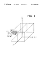
- FIG. 6 is an example of a three dimensional LUT (look up table) used for color gamut compression according to the embodiment
- FIG. 7 is an expanded view of one of a cubic including input values of L*, a*, and b* to the LUT in FIG. 6;
- FIG. 8 is a flowchart showing a process to display an image on a color monitor after applying color reproduction process to input color image data according to the first embodiment
- FIG. 9 is a flowchart showing a process in which whether or not the color image data to be processed is within a color gamut of an output device is determined, and the image is either displayed or not displayed on a color monitor on the basis of the determined result according to the embodiment;
- FIG. 10 is an example of a color gamut of a printer inside of a L* a* b* solid according to the embodiment
- FIG. 11 is an example showing a case where a color gamut of a monitor or a printer is defined by an area in a two dimensional plane of a* and b*, constructed with rectangular lattices, which is obtained by slicing a three dimensional color solid in the direction perpendicular to the L* axis according to a first embodiment;
- FIG. 12 shows an example of a color gamut data table in a case where the gamut of a monitor or a printer is defined by an area constructed with rectangular lattices according to the first embodiment
- FIG. 13 is a flowchart illustrating a process of checking the color gamut on the basis of the color gamut data table in FIG. 12;
- FIG. 14 is a flowchart illustrating a process of checking the color gamut on the basis of the color gamut data table in FIG. 12;
- FIG. 15 shows an example in a case where the color gamut of a monitor or a printer is defined by the two dimensional range of a* and b*, constructed with rectangular lattices, which is obtained by slicing the three dimensional color solid in the direction perpendicular to the L* axis according to a second embodiment;
- FIG. 16 is an address table where a top address of the color gamut data table in FIG. 17 is stored according to the second embodiment
- FIG. 17 is an example of a color gamut data table in a case where the gamut of a monitor or a printer is defined in two dimensional coordinate range according to the second embodiment;
- FIG. 19 is a flowchart showing a process of checking the color gamut on the basis of the tables, shown in FIGS. 16 and 17, which are for displaying the color gamuts according to the second embodiment;
- FIG. 20 is a flowchart showing a process of checking the color gamut on the basis of the tables, shown in FIGS. 16 and 17, which are for displaying the color gamuts according to the second embodiment;
- FIG. 21 is a flowchart showing a process of checking the color gamut on the basis of the tables, shown in FIGS. 16 and 17, which are for displaying the color gamuts according to the second embodiment;
- FIG. 22 is an example of a case where a gamut of a monitor or a printer is defined by bit map in the two dimensional area of a* and b*, constructed with rectangular lattices, which is obtained by slicing the three dimensional color solid in the direction perpendicular to the L* axis according to a third embodiment;
- FIG. 23 is an example of a bit map table in a case where the gamut in FIG. 22 is defined by bit map according to the third embodiment
- FIG. 24 shows an address table storing a top address of the color gamut data table in FIG. 23, as an example, according to the third embodiment
- FIG. 25 is a flowchart showing a process of checking the color gamut on the basis of the tables, shown in FIGS. 23 and 24, for displaying the color gamuts according to the third embodiment;
- FIG. 26 is a flowchart showing a process of checking the color gamut on the basis of the tables, shown in FIGS. 23 and 24, for displaying the color gamuts according to the third embodiment;
- FIG. 27 is an example of a case where a gamut of a monitor or a printer is defined by an area, surrounded by coordinate points and lines which connect the coordinate points in the two dimensional area of a* and b*, constructed with rectangular lattices, which is obtained by slicing the three dimensional color solid in the direction perpendicular to the L* axis according to a fourth embodiment;
- FIG. 28 is a color gamut data table in a case where a reproduction area of a monitor or a printer is defined by an area which is surrounded by coordinate points and lines which connect the coordinate points according to the fourth embodiment;
- FIG. 29 is a flowchart of checking the color gamut on the basis of the color gamut data table shown in FIG. 28 according to the fourth embodiment.
- FIG. 30 is a flowchart of checking the color gamut on the basis of the color gamut data table shown in FIG. 28 according to the fourth embodiment
- FIG. 31 is an example of color reproduction by a color management system
- FIG. 32 is an example showing differences in color gamut among devices
- FIG. 33 composed of FIGS. 33A-33E, shows an example of a color gamut compression
- FIG. 34 shows an example of a conventional method of checking color reproduction of a device.
- FIG. 31 shows an example of color reproduction by a color management system.
- a color input/output device in FIG. 31 a basic color scanner, color monitor, and color printer are considered.
- a color reproduction process is performed in consideration with characteristics of those three devices.
- the process is composed of following four color space conversion processes, shown by arrows in FIG. 31 .
- a process to preview an image to be printed by a printer on the monitor is a process to preview an image to be printed by a printer on the monitor.
- FIG. 1 is a block diagram showing a circuit configuration of an image processing system according to an embodiment of the present invention.
- the image processing system of the present embodiment comprises a color monitor 1 , host computer 2 , and color printer 3 .
- the host computer 2 process image data, instructs the color monitor 1 to display the processed result and also instructs the color printer 3 to print.
- the host computer 2 comprises a monitor interface 21 for interchanging data with the color monitor 1 ; VRAM 22 for maintaining display data used for monitor display; CPU 23 including ROM, RAM, and the like, for controlling the entire system; a frame memory 24 used for temporary storing image information to be displayed on the monitor; a print buffer 25 used for printer output; a printer interface 26 for interchanging data with the color printer 3 ; a color gamut information memory 27 for storing information for displaying a color gamut, such as a color gamut data table; a color gamut checking unit 28 for determining whether or not input color image data is in the color gamut; color converter 29 for converting color spaces relating color reproduction; and color reproduction processor 2 a for reproducing color on the basis of the determined result by the color gamut checking unit 28 .
- the host computer 2 reads a set of input color image data to be processed (luminance data of R, G, B) which is generated at step S 10 in advance or sent from another device, such as the scanner, then the process moves to step S 11 .
- the input color image data to be processed in the present embodiment depends on an input device, such as a scanner, and the data is RGB data defined based on colorimetry (values of chromaticity of R, G, B, and white are definite).
- the read RGB data is converted into data in DIE 1931 standard calorimetric system (indicated as “XYZ data”, hereinafter) which is defined by CIE (Commission Internationale de l'Eclairage) by a color converter 29 at step S 11 , the process proceeds to step S 12 .
- the XYZ data converted by the color converter 29 at step S 11 , is further converted into L*a*b* data, then the process goes to step S 13 .
- the L*a*b* data is converted into CMY (cyan, magenta, yellow) data for a printer, and the process moves to step S 14 .
- step S 14 the CMY data is stored in the print buffer 25 , then the process proceeds to step S 15 .
- step S 15 whether or not there is any remaining input color image data is checked. If there is, the process goes back to step S 10 .
- step S 16 the process moves to step S 16 , and the CMY data, stored in the print buffer 25 , is sent to the color printer 3 via the printer I/F 26 . After an image is printed out by the color printer 3 , the process is completed.
- the input color image data to be processed in the embodiment is the RGB data defined based on colorimetry (values of chromaticity of R, G, B, and white are definite), thus equations shown in FIGS. 3 and 4 show the relationship between RGB data and XYZ data which is defined by the CIE. Therefore, the equations in FIGS. 3 and 4 can be used in a process at step S 11 in FIG. 2.
- FIG. 5 is an example of a process at step S 12 in FIG. 2 .
- Xn, Yn, and Zn in FIG. 5 are determined depending upon a kind of used CIE standard light source.
- Step S 13 in FIG. 2 is a conversion process, including color gamut compression, to convert the L*a*b* data including colors beyond the color gamut of a printer to the CMY data which is within the color gamut of the printer.
- FIG. 33 composed of FIGS. 33A-33E, shows an example of color gamut compression.
- Methods of color gamut compression are used to convert image data, an example of which is shown in FIG. 33A, to color data which can be expressed by an output device, an example of which is shown in FIG. 33 B. Three general examples are described below.
- the first method is to use a sense of human beings as shown in FIG. 33 C. This is used to set the lightest and the darkest colors of the image data to the lightest and the darkest colors which can be expressed by the output device, respectively, and to convert other colors of the image data so that they are expressed in relative darkness between the lightest and the darkest colors to be expressed by the output device.
- the second method is to maintain the colors in the common color gamut of the image data and the output device, and to convert the color of image data outside of the common color gamut onto the border of the gamut of the output device with the intensity being maintained.
- the third method, shown in FIG. 33E, is to maintain chromaticity of the colors outside of the common color gamut of the image data and the output device, and to compress them.
- the example of the LUT is a three dimensional table composed of a plurality of rectangular solids formed by dividing a color solid in a three dimensional space of L*a*b* in each coordinate direction at a uniform interval ( ⁇ L*, ⁇ a*, ⁇ b*). At each intersection of lattices, namely each corner of the rectangular solid, a value of CMY corresponding to a sampling value of L*a*b* is stored.
- FIG. 7 is an expanded view of one of the rectangular solids including a L*a*b* value inputted to the LUT in FIG. 6 .
- the z direction is L* axis
- x direction is a* axis
- y direction is b* axis.
- the input L*a*b* value is at a point P.
- the CMY value corresponding to the input L*a*b* value can be obtained by using the LUT and the adding process.
- the host computer 2 reads a set of input color image data (luminance data for RGB) at step S 20 , as at step S 10 in FIG. 2, then the process proceeds to step S 21 .
- the input color image data which is RGB data defined based on colorimetry (values of chromaticity of R, G, B, and white are definite) depends on the kind of input device.
- step S 21 the read RGB data is converted into XYZ data, determined by CIE, in the color converter 29 , then the process proceeds to step S 22 .
- step S 22 the color converter 29 further converts the XYZ data into RGB data depending on characteristics of a color monitor, after that the process moves to step S 23 .
- step S 23 the RGB data for a monitor is stored in the frame memory 24 , and the process proceeds to step S 24 .
- step S 24 whether or not there is remaining input color data is checked. If there is, the process goes back to step S 20 .
- step S 25 If there is no input color image data left, the process moves to step S 25 , and the RGB data for the monitor which is stored in the frame memory is displayed on the color monitor 1 by using the VRAM 22 , and the process is completed.
- the input color image data and the monitor RGB data are RGB data defined based on colorimetry (values of chromaticity of R, G, B, and white are definite), there is relationship between aforesaid data and XYZ data determined by CIE as shown by equations in FIGS. 3 and 4. It is possible to apply the relationship equation in FIG. 3 in the process at step S 21 , and the relationship equation in FIG. 4, in the process at step S 22 .
- color image data for example, R, G, B luminance data which is generated by utilizing an application software or the like
- color printer 3 a characteristic process of the embodiment, in which it is checked on the color monitor 1 whether or not color image data (for example, R, G, B luminance data which is generated by utilizing an application software or the like) to be processed is in a color gamut of the color monitor 1 or the color printer 3 , and an image is displayed on the color monitor 1 in accordance with the checked result.
- color image data for example, R, G, B luminance data which is generated by utilizing an application software or the like
- FIG. 9 is a flowchart showing a process of checking the color gamut, in the host computer 2 , especially in the color gamut check unit 28 , in which it is checked whether or not data, obtained by transforming color image data (R, G, B luminance data) which is generated by using an application software or the like on the color monitor 1 so as to be in a color space of an output device, such as the color monitor 1 or of the color printer 3 , is in a color gamut of the output device, and a process to display an image on the color monitor 1 in accordance with the checked result.
- RGB transforming color image data
- FIG. 9 is a flowchart showing a process of checking the color gamut, in the host computer 2 , especially in the color gamut check unit 28 , in which it is checked whether or not data, obtained by transforming color image data (R, G, B luminance data) which is generated by using an application software or the like on the color monitor 1 so as to be in a color space of an output device, such as the color monitor 1 or
- the host computer 2 reads color (a set of R, G, B luminance data) to be checked for a color gamut at step S 30 , and the process moves to step S 31 .
- RGB data which depends on the characteristics of the color monitor 1 , and defined on the basis of colorimetry (values of chromaticity of R, G, B, and white are definite) is used as the color to be checked.
- step S 31 the read RGB data at step S 30 is converted into XYZ data, defined by CIE, by the color converter 29 , then the process moves to step S 32 .
- step S 32 the XYZ data is further converted into L*a*b* data by the color converter 29 , and the process proceeds to step S 33 .
- step S 33 whether or not the converted L*a*b* data can be reproduced by the color printer 3 is checked. If so, a flag is turned ON, whereas, if not, a flag is turned OFF, and the process moves to step S 34 .
- step S 34 whether the flag set at step S 33 is ON or OFF is checked. If the flag is not ON, the process moves to step S 36 , and the checked color is displayed in white, and a process is completed. Whereas, if the flag is ON, since it is possible to reproduce colors without processing any further, the process moves to step S 35 , and the checked color is displayed on the color monitor 1 without being processed, then the process is completed.
- the aforesaid process is applied to all sets of the input image data.
- the checked color is faithfully reproduced on the color monitor 1 .
- the checked color is displayed in white on the color monitor 1 to inform a user, so that the user can recognize which color at which part is outside of the color gamut.
- the checked color is represented by white when the color is outside of a color gamut. However, it is not limited to white as long as the user knows that the checked color is outside of the color gamut, thus black can be used instead of white, for instance.
- a feature of the embodiment is to have data of the range of lattice as color reproduction information and is to use the information to perform color gamut check. The feature will be described in accordance with the following four embodiments.
- values of ⁇ L*, ⁇ a*, and ⁇ b* can be the minimum value which L*, dispersion data, can take as a predetermined interval.
- a gamut of a printer is defined by an area including all the area inside of a bold line in FIG. 11, and the color gamut is checked based on the defined area information.
- the area be defined by two points, (a max , b max ) and (a min , b min ). Since the size of the area changes depending on the value of L*, an example of a color gamut data table in the first embodiment is shown in FIG. 12 . In this embodiment, tables are stored in the color gamut information memory 27 .
- An area surrounded by bold line in FIG. 11 shows the color gamut.
- FIGS. 13 and 14 are flowcharts of checking the color gamut on the basis of the color gamut data table in FIG. 12 by the host computer 2 , especially by the color reproduction checking unit 28 .
- the host computer 2 sets a pointer at the top of the color gamut data table in FIG. 12 at step S 100 , and the process proceeds to step S 101 .
- a constant n is set to 1 and L1 is set to L* min , then the process moves to step S 102 .
- the read L* is compared with L 1 . If the values of L* and L1 are not identical, then the process moves to step S 103 , thereat L n+1 is set to L n + ⁇ L, then the process further moves to step S 104 .
- values of n and pointer are incremented by 1, and process goes back to step S 102 .
- step S 105 the read a* is compared with a nmin . If a* is smaller than a nmin , then the process moves to step S 106 , thereat a flag is set OFF and the process is completed.
- RGB data of a color to be checked is RGB data defined on the basis of colorimetry (values of chromaticity of R, G, B, and white are definite), therefore, the equations in FIGS. 3 and 4 are held to represent a relationship between the RGB data and the XYZ data which is defined by CIE. It is possible to use the equation in FIG. 3 in the process at step S 31 .
- a process at step S 32 in FIG. 9 is the same as the aforesaid process in FIG. 5 .
- Xn, Yn, and Zn are the value depending on type of CIE standard light source to be used.
- L*a*b* data of the color to be checked which is obtained at step S 32 , is checked whether or not it is within color gamut, and the result is outputted as a value of a flag.
- a color gamut of a printer is included in a L*a*b* color solid, and as shown in FIG. 10, the range can be designated by using the three dimensional solids which are produced by dividing the color solid of L*a*b* three dimensions in the each coordinate direction at a fixed interval ( ⁇ L*, ⁇ a*, ⁇ b*), whose process is the same as the one in FIG. 6 .
- the range can be designated by using the three dimensional lattices which are produced when the color solid of L*a*b* three dimensions is divided in the each coordinate direction at a fixed interval ( ⁇ L*, ⁇ a*, ⁇ b*), similarly.
- the cut surface is the two dimensional plane of a* and b* which is constructed with rectangular (square, in the first embodiment) areas. Lengths of sides of each rectangular area are ⁇ a* and ⁇ b*, as shown in FIG. 11 . Note that the area surrounded by a closed bold line indicates a range of lattices including the color gamut of a monitor or a printer in the sliced two dimensional plane perpendicular to L*.
- step S 105 If it is determined at step S 105 that a* is not smaller than a nmin , then the process moves to step S 107 , thereat read a* is compared with a nmax . If a* is larger than a nmax , then the process moves to step S 106 , where a flag is set OFF and the process is completed.
- step S 107 If a* is not larger than a nmax at step S 107 , then the process proceeds to step S 108 , where read b* and b nmin are compared. If b* is smaller than b nmin , the process moves to step S 106 , thereat a flag is set OFF and the process is completed.
- step S 108 If it is determined at step S 108 that b* is not smaller than b nmin , then the process proceeds to step S 109 , and the read b* and b nmax are compared. If b* is larger than bnmax, the process moves to step S 106 , thereat a flag is set OFF and the process is completed.
- step S 110 If b* is not larger than bnmax, then the process proceeds to step S 110 , and the process is completed after a flag is set ON.
- a color gamut of a printer or a monitor is defined by a two dimensional coordinate range including all the area inside of a bold line in FIG. 15, and the color gamut is checked based on the defined area information.
- the coordinate ranges is decided in accordance with a min and a max in each b* lattice range in lattice range between b* min and b* max .
- These tables indicating the color gamuts are stored in the color gamut information memory 27 .
- FIG. 16 is an address table which stores top addresses of the aforesaid color gamut data table shown in FIG. 17 in the second embodiment. As shown in FIG. 16, in the address table of the second embodiment, a number L within a range between L* min and L* max is m (constant).
- FIGS. 19 to 21 are flowcharts showing a process for checking a color gamut on the basis of a information table for representing a color gamut described in FIGS. 16 and 17 by the host computer 2 , especially the color gamut checking unit 28 .
- a process of checking a color gamut in the second embodiment will be described below with reference to FIGS. 19 to 21 .
- a pointer is set at the top of the address table shown in FIG. 16, and the process moves to step S 201 .
- a constant n is set to 1 and L 1 is set to L* min , then the process further proceeds to step S 202 .
- the read L* is compared with L 1 . If the values of L* and L 1 are not identical, then the process moves to step S 203 , thereat L n+1 is set to L n + ⁇ L and the process proceeds to step S 204 .
- n and pointer are incremented by 1, and the process goes back to step S 202 .
- step S 205 thereat an address which is stored in the area that the pointer indicates is fetched, then the process further proceeds to step S 206 .
- step S 206 the pointer is set to the fetched address, and the process moves to step S 207 in FIG. 20 .
- step S 207 the read b* is compared with b min . If b* is smaller than b min , then the process moves to step S 208 in FIG. 21, thereat a flag is set OFF to complete the process.
- step S 207 if b* is not smaller than b min at step S 207 , then the process moves to step S 209 , thereat the read b* is compared with b max . If b* is larger than b max , then the process moves to step S 208 in FIG. 21, thereat a flag is set OFF to complete the process.
- step S 209 If it is determined at step S 209 that b* is not larger than b max , then the process proceeds to step S 210 , thereat the constant m is set to 1 and b1 is set to b* min , and the process moves to S 211 .
- step S 211 b m+1 is set to b m + ⁇ b, and the process proceeds to step S 212 .
- step S 212 whether or not the read b* fulfills a relationship, b m ⁇ b* ⁇ b m+1 , is checked. If not, the process proceeds to step S 213 , thereat m and pointer are incremented by 1, then the process goes back to step S 211 .
- step S 214 the process moves to step S 214 in FIG. 21, thereat the constant j is set to 1, and the process proceeds to step S 215 .
- step S 215 the read a* is compared with a mjmin . If a* is smaller than the a mjmin , the process moves to step S 208 , thereat a flag is set OFF to complete the process.
- step S 215 If it is determined at step S 215 that a* is not smaller than a mjmin , then the process proceeds to step S 216 , thereat the read a* and a mjmin are compared. If a* is larger than amjmin, the process moves to step S 208 , thereat a flag is set OFF to complete the process.
- step S 216 If it is determined at step S 216 that a* is not larger than a mjmin , the process proceeds to step S 217 , thereat i n is compared with j. If i n and j have the same value, then the process moves to step S 219 , where a flag is set ON, and the process is completed.
- step S 217 If it is determined at step S 217 that i n and j do not have the same value, then the process proceeds to step S 218 , thereat j is incremented by 1, and the process goes back to step S 215 .
- a gamut of a monitor or a printer is defined by bit map tables corresponding to a lattice area, and the color gamut is checked based on the defined bit map information.
- a bit map table is a color gamut data table, and its top is the bit corresponding to a lattice including the left uppermost point, (a min , b max ), in FIG. 22 .
- FIG. 22 let an area surrounded by a bold line be a color gamut of a monitor or a printer, and let the bits outside of the color gamut be OFF, and the bits inside of the range be ON, the bit map table corresponding a case shown in FIG. 22 is represented as in FIG. 23 .
- FIG. 24 is an address table where the top address of a color gamut data table, such as the one shown in FIG. 23, is stored.
- the number of L within the range between L* min and L* max is m (constant).
- the tables shown in FIGS. 23 and 24 are stored in the color gamut information memory 27 .
- FIGS. 25 and 26 are flowcharts for checking the color gamut on the basis of information tables representing the color gamut data tables in FIGS. 23 and 24 by the host computer 2 , especially by the color reproduction check unit 28 .
- the process to check the color gamut according to the third embodiment will be described with reference to FIGS. 25 and 26.
- a pointer is set at the top of an address table in FIG. 24, then the process proceeds to step S 301 .
- the constant n is set to 1 and L 1 is set to L* min , and the process moves to step S 302 .
- the read L* is compared with L 1 . If the values of L* and L 1 is not the same, the process moves to step S 303 , thereat L n+1 is set to L n + ⁇ L, and the process further moves to step S 304 .
- n and the pointer are incremented by 1, then the process goes back to step S 302 .
- step S 302 determines whether L* and L 1 have the same value. If it is determined at step S 302 that L* and L 1 have the same value, then the process proceeds to step S 305 , thereat an address which is stored in the area that the pointer indicates is fetched, and the process further proceeds to step S 306 .
- a pointer is set to the address fetched at step S 306 , then the process moves to step S 307 in FIG. 26 .
- step S 307 by using a* and b*, a value obtained by dividing (a* ⁇ a* min ) by ⁇ a is set to a constant p, and a value obtained by dividing (b* max ⁇ b*) by ⁇ b is set to a constant q, then the process moves to step S 308 .
- step S 308 a value obtained by adding 1 to the integer part of p is set to a constant r, a value obtained by adding 1 to the integer part of q is set to a constant s, then the process proceeds to step S 309 .
- step S 309 the pointer is moved r bits to the right and s bits down, and the process moves to step S 310 .
- step S 310 the bit indicated by the pointer is checked. In a case where the bit indicated by the pointer is not ON, the process moves to step S 311 , thereat a flag is set OFF to complete the process.
- step S 312 thereat the flag is set ON to complete the process.
- the color gamut can be easily checked on the basis of the information tables in FIGS. 23 and 24 representing the color gamuts.
- a gamut of a monitor or a printer is defined by an area surrounded by coordinate points as shown in FIG. 27, then a color gamut is checked on the basis of the information on the area.
- FIG. 27 shows an example of a gamut in L* min which is expressed with the 20 coordinate points in this example. Since the size of the surrounded area changes depending on a value of L*, an example of a color gamut data table which corresponds to the value of L* is shown in FIG. 28 in the fourth embodiment.
- the range of L* is from L* min to L* max , and there are values, in the table, of coordinate points corresponding to the various L*'s.
- a number of L in the range between L* min and L* max is m (constant).
- a number of constants i 1 , i 2 , . . . , i n is as same as the number of coordinate points each of which is corresponding each value of L*.
- the table in the fourth embodiment is stored in the color gamut information memory 27 .
- FIGS. 29 and 30 are flowcharts of checking the color gamut on the basis of the color gamut data table in FIG. 28 by the host computer 2 , especially by the color reproduction check unit 28 .
- the process of checking the color gamut in the fourth embodiment will be explained with reference to flowcharts in FIGS. 29 and 30 below.
- a pointer is set at the top of the color gamut data table in FIG. 28 at step S 400 in FIG. 29, and the process proceeds to step S 401 .
- a constant j is set to 1 and L* min is set to L 1 , then the process moves to step S 402 .
- the read value of L* is compared with L 1 . If the values of L* and L 1 are not equal, the process moves to step S 403 , thereat L j + ⁇ L is set to L j+1 , and the process proceeds to step S 404 .
- j and the pointer are incremented by 1, and the process goes back to step S 402 .
- step S 405 thereat a number of a coordinate point r is fetched from an area where the pointer designates, then the process moves to step S 406 .
- step S 406 a constant k is set to 1, then the process moves to step S 407 in FIG. 30 .
- step S 407 a j ⁇ k and b j ⁇ k are fetched from an area where the pointer designates and the process proceeds to step S 408 .
- step S 408 is compared with r at step S 408 . If r is larger than k, then the process proceeds to step S 409 , and after k is incremented by 1, the process goes back to step S 407 .
- step S 410 If it is determined at step s 408 that r is not larger than k, the process proceeds to step S 410 , and whether or not a* and b* are included in a closed area surrounded by coordinate points, (a j ⁇ 1 , b j ⁇ 1 ), (a j ⁇ 2 , b j ⁇ 2 ), . . . , (a j ⁇ k , b j ⁇ k ), fetched at step S 411 is checked. If not, the process proceeds to step S 412 , thereat a flag is set OFF, and the process is completed.
- step S 411 if a* and b* are included in the closed area surrounded by coordinate points, (a j ⁇ 1 , b j ⁇ 1 ), (a j ⁇ 2 , b j ⁇ 2 ), . . . , (a j ⁇ k , b j ⁇ k ), fetched at step S 411 , the process proceeds to step S 413 , thereat the flag is set ON, and the process is completed.
- the color gamut is easily checked by using the color gamut data table in FIG. 28 .
- the present invention can be applied to a system constituted by a plurality of devices, or to an apparatus comprising a single device. Furthermore, the invention is applicable also to a case where the object of the invention is attained by supplying a program to a system or apparatus.
- a color space representing a color gamut is not limited to the L* a* b* color space, and the standard RGB color space, such as NTSC, and the like can be used instead.
- an adding method can be added to the aforesaid method of checking a color gamut.
- the present invention is not limited to an apparatus which displays the checked result of a color gamut, and can be applicable to any kind of apparatus performing color reproduction on the basis of the checked result of the color gamut.
- a color gamut for realizing a color gamut checking function can be easily confirmed, thereby quality of determining color gamut can be improved as well as color reproduction processing time can be shortened.
Abstract
The host computer 2 defines a color gamut as a solid of a three dimensional space to represent a color reproduction area of a color reproduction device, and instructs to display the color gamut in accordance with combinations of information on the color reproduction area on the basis of a second and a third axes extending to both the positive and negative directions in a plane perpendicular to a first axis of the defined three dimensional space and coordinates of the first axis. For example, the information on the color reproduction area in the plane perpendicular to the first axis can be represented by a two dimensional area, a two dimensional coordinate area, bit map data, or two dimensional vector data, thereby the color gamut for realizing a color gamut checking function is easily confirmed.
Description
The present invention relates to a color gamut displaying method, an image processing method, and an apparatus capable of utilizing the methods, which are suitable for a color management system, and the like, for instance, reproducing colors faithfully in consideration with characteristics of a color input/output device.
As shown in FIG. 32, color ranges which can be reproduced by devices, such as a scanner, a monitor, and a printer, are different each other.
In FIG. 32, x and y denotes axes for chromaticity, and insides of closed areas are color gamuts.
In other words, the key to reproduce colors after considering the difference in a color gamut is how to deal with portions of ranges which are not common to different devices. For example, when transformation from a monitor color space to a printer color space is considered, a major problem is that which color should be used to express a color outside of a color gamut of a printer. A process to deal with the above-said problem is called a color gamut compression process.
A color management system has major functions, such as a function of performing the color gamut compression process for faithfully reproducing colors in consideration with characteristics of a color input/output device, as well as a color gamut checking function for checking whether or not it is possible to reproduce a color by an output device. The latter function is used to determine whether or not color data, included in an application software and the like, can be reproduced by an output device (e.g., printer monitor).
Specifically, a method which is shown in FIG. 34 is suggested by the present inventor.
According to the method, a color gamut of a printer is defined by a color reproduction solid whose shape is a hexahedron, determined by peaks of red, green, blue, cyan, magenta, yellow, white, and black. Then each surface of the hexahedron is divided into two triangles to obtain total of twelve areas. Finally, image data is determined whether it is inside or outside of the areas, thereby it is determined if the image data is in the color gamut or not.
However, there are problems to be solved in the aforesaid method.
(1) A real color gamut of a printer has a three dimensional solid which is too complicated to express with a hexahedron, thus precision of checking the color gamut is low.
(2) It is not a simple process to determine whether or not image data is inside of the twelve areas, thus it requires a long time to complete the process.
The present invention has been made in consideration of the above situation, and has as its object to provide a color gamut expression method for realizing a color gamut checking function which improves precision of checking and shortens a processing time in a color management system and the like.
Further, another object of the present invention is to provide an image processing method and an apparatus utilizing the method, capable of converting input image data into image data which enables to reproduce inputted image data more faithfully by a color reproduction device.
Especially, it is an object to provide an image processing method and apparatus which are most suitable for a checking function which checks input image data and a color gamut of a printer, and which reproduce colors designated by the input image data more faithfully.
The foregoing object is attained by providing an apparatus, where the color gamut is defined by a solid in a three dimensional space, comprising color gamut expression means for expressing defined color gamut by combinations of color gamut data on the basis of a second and a third axes extending to both the positive and negative directions on a plane perpendicular to a first axis of the three dimensional space and coordinates of the first axis.
Further, the foregoing object is attained by providing an apparatus comprising processing means which defines a color gamut by a solid in a three dimensional space, and determines the color gamut of the color reproduction device by combinations of color gamut data on the basis of second and third axes extending to both the positive and negative directions on a plane perpendicular to a first axis of the three dimensional space and coordinates of the first axis, and processes an input color image data depending upon whether or not the input color image data is within the determined color gamut.
Furthermore, the foregoing object is attained by providing an apparatus comprising storage means for storing information on a defined color gamut expressed by combinations of color gamut data on the basis of second and third axes extending to both the positive and negative directions ona plane perpendicular to a first axis of a three dimensional space where a color gamut of a color reproduction device is defined as a solid and coordinates of the first axis, determination means for determining whether or not input image data is within the defined color gamut on the basis of the information stored in the storage means, and image processing means for processing the input image data on the basis of the result of determination means.
According to a constitution as described above, there can be provided an image processing method capable of converting input image data into image data which enables to reproduce inputted image data more faithfully by a color reproduction device.
Further, the color gamut for realizing the color gamut checking function is easily confirmed, the precision of determining the color gamut can be improved, as well as the time to process the color reproduction can be shortened.
Other features and advantages of the present invention will be apparent from the following description taken in conjunction with the accompanying drawings, in which like reference characters designate the same or similar parts throughout the figures thereof.
The accompanying drawings, which are incorporated in and constitute a part of the specification, illustrate embodiments of the invention and, together with the description, serve to explain the principles of the invention.
FIG. 1 is a block diagram showing a configuration of an image processing system according to an embodiment of the present invention;
FIG. 2 is a flowchart showing a process to output an image by a color printer after applying color reproduction process to input color image data according to the embodiment;
FIG. 3 is an equation in matrix notation, showing relationship between XYZ data, defined by CIE, and RGB data according to the embodiment;
FIG. 4 is an equation in matrix notation, showing relationship between the RGB data, defined by CIE, and XYZ data according to the embodiment;
FIG. 5 explains an example of converting the XYZ data, defined by the CIE, into L* a* b* according to the embodiment;
FIG. 6 is an example of a three dimensional LUT (look up table) used for color gamut compression according to the embodiment;
FIG. 7 is an expanded view of one of a cubic including input values of L*, a*, and b* to the LUT in FIG. 6;
FIG. 8 is a flowchart showing a process to display an image on a color monitor after applying color reproduction process to input color image data according to the first embodiment;
FIG. 9 is a flowchart showing a process in which whether or not the color image data to be processed is within a color gamut of an output device is determined, and the image is either displayed or not displayed on a color monitor on the basis of the determined result according to the embodiment;
FIG. 10 is an example of a color gamut of a printer inside of a L* a* b* solid according to the embodiment;
FIG. 11 is an example showing a case where a color gamut of a monitor or a printer is defined by an area in a two dimensional plane of a* and b*, constructed with rectangular lattices, which is obtained by slicing a three dimensional color solid in the direction perpendicular to the L* axis according to a first embodiment;
FIG. 12 shows an example of a color gamut data table in a case where the gamut of a monitor or a printer is defined by an area constructed with rectangular lattices according to the first embodiment;
FIG. 13 is a flowchart illustrating a process of checking the color gamut on the basis of the color gamut data table in FIG. 12;
FIG. 14 is a flowchart illustrating a process of checking the color gamut on the basis of the color gamut data table in FIG. 12;
FIG. 15 shows an example in a case where the color gamut of a monitor or a printer is defined by the two dimensional range of a* and b*, constructed with rectangular lattices, which is obtained by slicing the three dimensional color solid in the direction perpendicular to the L* axis according to a second embodiment;
FIG. 16 is an address table where a top address of the color gamut data table in FIG. 17 is stored according to the second embodiment;
FIG. 17 is an example of a color gamut data table in a case where the gamut of a monitor or a printer is defined in two dimensional coordinate range according to the second embodiment;
FIG. 18 is a color gamut data table in a case where Δa=Δb=1 in FIG. 15 according to the second embodiment;
FIG. 19 is a flowchart showing a process of checking the color gamut on the basis of the tables, shown in FIGS. 16 and 17, which are for displaying the color gamuts according to the second embodiment;
FIG. 20 is a flowchart showing a process of checking the color gamut on the basis of the tables, shown in FIGS. 16 and 17, which are for displaying the color gamuts according to the second embodiment;
FIG. 21 is a flowchart showing a process of checking the color gamut on the basis of the tables, shown in FIGS. 16 and 17, which are for displaying the color gamuts according to the second embodiment;
FIG. 22 is an example of a case where a gamut of a monitor or a printer is defined by bit map in the two dimensional area of a* and b*, constructed with rectangular lattices, which is obtained by slicing the three dimensional color solid in the direction perpendicular to the L* axis according to a third embodiment;
FIG. 23 is an example of a bit map table in a case where the gamut in FIG. 22 is defined by bit map according to the third embodiment;
FIG. 24 shows an address table storing a top address of the color gamut data table in FIG. 23, as an example, according to the third embodiment;
FIG. 25 is a flowchart showing a process of checking the color gamut on the basis of the tables, shown in FIGS. 23 and 24, for displaying the color gamuts according to the third embodiment;
FIG. 26 is a flowchart showing a process of checking the color gamut on the basis of the tables, shown in FIGS. 23 and 24, for displaying the color gamuts according to the third embodiment;
FIG. 27 is an example of a case where a gamut of a monitor or a printer is defined by an area, surrounded by coordinate points and lines which connect the coordinate points in the two dimensional area of a* and b*, constructed with rectangular lattices, which is obtained by slicing the three dimensional color solid in the direction perpendicular to the L* axis according to a fourth embodiment;
FIG. 28 is a color gamut data table in a case where a reproduction area of a monitor or a printer is defined by an area which is surrounded by coordinate points and lines which connect the coordinate points according to the fourth embodiment;
FIG. 29 is a flowchart of checking the color gamut on the basis of the color gamut data table shown in FIG. 28 according to the fourth embodiment;
FIG. 30 is a flowchart of checking the color gamut on the basis of the color gamut data table shown in FIG. 28 according to the fourth embodiment;
FIG. 31 is an example of color reproduction by a color management system;
FIG. 32 is an example showing differences in color gamut among devices;
FIG. 33, composed of FIGS. 33A-33E, shows an example of a color gamut compression;
FIG. 34 shows an example of a conventional method of checking color reproduction of a device.
Preferred embodiments of the present invention will be described in detail in accordance with the accompanying drawings.
FIG. 31 shows an example of color reproduction by a color management system. As a color input/output device in FIG. 31, a basic color scanner, color monitor, and color printer are considered.
In the color management system, a color reproduction process is performed in consideration with characteristics of those three devices. The process is composed of following four color space conversion processes, shown by arrows in FIG. 31.
1. Conversion from a color space of the scanner to a color space of the monitor;
A process to display data of a photograph read by the scanner onto the monitor faithfully.
2. Conversion from a color space of the scanner to a color space of the printer;
A process to print data of a photograph read by the scanner by the printer faithfully.
3. Conversion from a color space of the monitor to a color space of the printer;
A process to print data, such as character and figure data, generated on the monitor by using an application software or the like, by a printer faithfully.
4. Conversion from a color space of the printer to a color space of the monitor;
A process to preview an image to be printed by a printer on the monitor.
Note that the aforesaid color spaces rely on the three devices, and the color gamuts differ from each other.
Following is an example of a conversion process from the color space of the monitor to the color space of the printer, as described above in 3.
FIG. 1 is a block diagram showing a circuit configuration of an image processing system according to an embodiment of the present invention.
As shown in FIG. 1, the image processing system of the present embodiment comprises a color monitor 1, host computer 2, and color printer 3. The host computer 2 process image data, instructs the color monitor 1 to display the processed result and also instructs the color printer 3 to print.
The host computer 2 comprises a monitor interface 21 for interchanging data with the color monitor 1; VRAM 22 for maintaining display data used for monitor display; CPU 23 including ROM, RAM, and the like, for controlling the entire system; a frame memory 24 used for temporary storing image information to be displayed on the monitor; a print buffer 25 used for printer output; a printer interface 26 for interchanging data with the color printer 3; a color gamut information memory 27 for storing information for displaying a color gamut, such as a color gamut data table; a color gamut checking unit 28 for determining whether or not input color image data is in the color gamut; color converter 29 for converting color spaces relating color reproduction; and color reproduction processor 2 a for reproducing color on the basis of the determined result by the color gamut checking unit 28.
A process to apply a color reproduction to input color image data and to output the processed image to the color printer 3 by the host computer 2 having aforesaid constitution, more specifically by the color reproduction processor 2 a, is described below with reference to a flowchart in FIG. 2.
In FIG. 2, the host computer 2 reads a set of input color image data to be processed (luminance data of R, G, B) which is generated at step S10 in advance or sent from another device, such as the scanner, then the process moves to step S11. Note that the input color image data to be processed in the present embodiment depends on an input device, such as a scanner, and the data is RGB data defined based on colorimetry (values of chromaticity of R, G, B, and white are definite).
The read RGB data is converted into data in DIE 1931 standard calorimetric system (indicated as “XYZ data”, hereinafter) which is defined by CIE (Commission Internationale de l'Eclairage) by a color converter 29 at step S11, the process proceeds to step S12. At step S12, the XYZ data, converted by the color converter 29 at step S11, is further converted into L*a*b* data, then the process goes to step S13. At step S13, the L*a*b* data is converted into CMY (cyan, magenta, yellow) data for a printer, and the process moves to step S14.
At step S14, the CMY data is stored in the print buffer 25, then the process proceeds to step S15. At step S15, whether or not there is any remaining input color image data is checked. If there is, the process goes back to step S10.
If there is not, the process moves to step S16, and the CMY data, stored in the print buffer 25, is sent to the color printer 3 via the printer I/F 26. After an image is printed out by the color printer 3, the process is completed.
As described above, the input color image data to be processed in the embodiment is the RGB data defined based on colorimetry (values of chromaticity of R, G, B, and white are definite), thus equations shown in FIGS. 3 and 4 show the relationship between RGB data and XYZ data which is defined by the CIE. Therefore, the equations in FIGS. 3 and 4 can be used in a process at step S11 in FIG. 2. Pij(i, j=1, 2, 3) in FIG. 3 and Qij(i, j,=1, 2, 3) in FIG. 4 are constants defined based on colorimetry of input color image data.
FIG. 5 is an example of a process at step S12 in FIG. 2. Xn, Yn, and Zn in FIG. 5 are determined depending upon a kind of used CIE standard light source.
Step S13 in FIG. 2 is a conversion process, including color gamut compression, to convert the L*a*b* data including colors beyond the color gamut of a printer to the CMY data which is within the color gamut of the printer.
There are several methods of color gamut compression.
FIG. 33, composed of FIGS. 33A-33E, shows an example of color gamut compression.
Methods of color gamut compression are used to convert image data, an example of which is shown in FIG. 33A, to color data which can be expressed by an output device, an example of which is shown in FIG. 33B. Three general examples are described below.
The first method is to use a sense of human beings as shown in FIG. 33C. This is used to set the lightest and the darkest colors of the image data to the lightest and the darkest colors which can be expressed by the output device, respectively, and to convert other colors of the image data so that they are expressed in relative darkness between the lightest and the darkest colors to be expressed by the output device.
The second method, shown in FIG. 33D, is to maintain the colors in the common color gamut of the image data and the output device, and to convert the color of image data outside of the common color gamut onto the border of the gamut of the output device with the intensity being maintained.
The third method, shown in FIG. 33E, is to maintain chromaticity of the colors outside of the common color gamut of the image data and the output device, and to compress them.
Further, there is a method which uses a three dimensional LUT (look up table) as one of the color gamut compression methods, and the LUT which is used for conversion by color gamut compression at step S13 according to the embodiment is shown in FIG. 6. The example of the LUT is a three dimensional table composed of a plurality of rectangular solids formed by dividing a color solid in a three dimensional space of L*a*b* in each coordinate direction at a uniform interval (ΔL*, Δa*, Δb*). At each intersection of lattices, namely each corner of the rectangular solid, a value of CMY corresponding to a sampling value of L*a*b* is stored.
FIG. 7 is an expanded view of one of the rectangular solids including a L*a*b* value inputted to the LUT in FIG. 6. Note that the z direction is L* axis, x direction is a* axis, and y direction is b* axis. Assume that the input L*a*b* value is at a point P.
When a left lower front point of the lattice is (xi, yi, zi) and ΔL*=Δa*=Δb*=1, and the displacement from the left lower front point to the point P is xf, yf, zf, then the coordinate points are shown in FIG. 7. Here, if the CMY value, stored at the each point of intersection of lattices, is denoted as U(x, y, z), then the CYM value of the point P, U(xi+xf, yi+yf, zi+zf) can be obtained by utilizing an adding method as shown by following equations. 
As above, the CMY value corresponding to the input L*a*b* value can be obtained by using the LUT and the adding process.
By performing the aforesaid color gamut compression, an image can be reproduced by a printer more faithfully to the original.
Next, a process to transmit data to the color monitor 1 after applying the color reproduction to the input color image data at the host computer 2, especially, the color reproduction processor 2 a, will be described below with reference to a flowchart in FIG. 8.
The host computer 2 reads a set of input color image data (luminance data for RGB) at step S20, as at step S10 in FIG. 2, then the process proceeds to step S21. There, the input color image data which is RGB data defined based on colorimetry (values of chromaticity of R, G, B, and white are definite) depends on the kind of input device.
At step S21, the read RGB data is converted into XYZ data, determined by CIE, in the color converter 29, then the process proceeds to step S22. At step S22, the color converter 29 further converts the XYZ data into RGB data depending on characteristics of a color monitor, after that the process moves to step S23. At step S23, the RGB data for a monitor is stored in the frame memory 24, and the process proceeds to step S24. At step S24, whether or not there is remaining input color data is checked. If there is, the process goes back to step S20.
If there is no input color image data left, the process moves to step S25, and the RGB data for the monitor which is stored in the frame memory is displayed on the color monitor 1 by using the VRAM 22, and the process is completed.
Since the input color image data and the monitor RGB data are RGB data defined based on colorimetry (values of chromaticity of R, G, B, and white are definite), there is relationship between aforesaid data and XYZ data determined by CIE as shown by equations in FIGS. 3 and 4. It is possible to apply the relationship equation in FIG. 3 in the process at step S21, and the relationship equation in FIG. 4, in the process at step S22. Pij (i, j=1, 2, 3) and Qij (i, j,=1, 2, 3) are constants determined on the basis of colorimetry of input color image data and of monitor RGB for the color monitor 1.
Next, referring to FIG. 9, there will be described a characteristic process of the embodiment, in which it is checked on the color monitor 1 whether or not color image data (for example, R, G, B luminance data which is generated by utilizing an application software or the like) to be processed is in a color gamut of the color monitor 1 or the color printer 3, and an image is displayed on the color monitor 1 in accordance with the checked result.
FIG. 9 is a flowchart showing a process of checking the color gamut, in the host computer 2, especially in the color gamut check unit 28, in which it is checked whether or not data, obtained by transforming color image data (R, G, B luminance data) which is generated by using an application software or the like on the color monitor 1 so as to be in a color space of an output device, such as the color monitor 1 or of the color printer 3, is in a color gamut of the output device, and a process to display an image on the color monitor 1 in accordance with the checked result.
In FIG. 9, the host computer 2 reads color (a set of R, G, B luminance data) to be checked for a color gamut at step S30, and the process moves to step S31. Note that RGB data which depends on the characteristics of the color monitor 1, and defined on the basis of colorimetry (values of chromaticity of R, G, B, and white are definite) is used as the color to be checked.
At step S31, the read RGB data at step S30 is converted into XYZ data, defined by CIE, by the color converter 29, then the process moves to step S32. At step S32, the XYZ data is further converted into L*a*b* data by the color converter 29, and the process proceeds to step S33. At step S33, whether or not the converted L*a*b* data can be reproduced by the color printer 3 is checked. If so, a flag is turned ON, whereas, if not, a flag is turned OFF, and the process moves to step S34.
At step S34, whether the flag set at step S33 is ON or OFF is checked. If the flag is not ON, the process moves to step S36, and the checked color is displayed in white, and a process is completed. Whereas, if the flag is ON, since it is possible to reproduce colors without processing any further, the process moves to step S35, and the checked color is displayed on the color monitor 1 without being processed, then the process is completed.
The aforesaid process is applied to all sets of the input image data.
Therefore, in a case where the color to be checked is within the color gamut of an output device, such as the color monitor 1 or of the color printer 3, the checked color is faithfully reproduced on the color monitor 1. Whereas in a case where the checked color is outside of the color gamut, the checked color is displayed in white on the color monitor 1 to inform a user, so that the user can recognize which color at which part is outside of the color gamut.
Note that the checked color is represented by white when the color is outside of a color gamut. However, it is not limited to white as long as the user knows that the checked color is outside of the color gamut, thus black can be used instead of white, for instance.
As seen in FIG. 10, the aforesaid range of lattice which includes the L*a*b* value inputted to the LUT shown in FIG. 6 differs depending on the value of L*. Therefore, a feature of the embodiment is to have data of the range of lattice as color reproduction information and is to use the information to perform color gamut check. The feature will be described in accordance with the following four embodiments.
It should be noted that values of ΔL*, Δa*, and Δb* can be the minimum value which L*, dispersion data, can take as a predetermined interval.
(First Embodiment)
According to a first embodiment, a gamut of a printer, one of output devices, is defined by an area including all the area inside of a bold line in FIG. 11, and the color gamut is checked based on the defined area information. Let the area be defined by two points, (amax, bmax) and (amin, bmin). Since the size of the area changes depending on the value of L*, an example of a color gamut data table in the first embodiment is shown in FIG. 12. In this embodiment, tables are stored in the color gamut information memory 27.
An area surrounded by bold line in FIG. 11 shows the color gamut.
Note that a number L within L*min and L*max is m (constant).
FIGS. 13 and 14 are flowcharts of checking the color gamut on the basis of the color gamut data table in FIG. 12 by the host computer 2, especially by the color reproduction checking unit 28.
First, the host computer 2 sets a pointer at the top of the color gamut data table in FIG. 12 at step S100, and the process proceeds to step S101. At step S101, a constant n is set to 1 and L1 is set to L*min, then the process moves to step S102. At step S102, the read L* is compared with L1. If the values of L* and L1 are not identical, then the process moves to step S103, thereat Ln+1 is set to Ln+ΔL, then the process further moves to step S104. At step S104, values of n and pointer are incremented by 1, and process goes back to step S102.
If the read L* has the same value as L1, then the process proceeds to step S105, and the read a* is compared with anmin. If a* is smaller than anmin, then the process moves to step S106, thereat a flag is set OFF and the process is completed.
RGB data of a color to be checked is RGB data defined on the basis of colorimetry (values of chromaticity of R, G, B, and white are definite), therefore, the equations in FIGS. 3 and 4 are held to represent a relationship between the RGB data and the XYZ data which is defined by CIE. It is possible to use the equation in FIG. 3 in the process at step S31. Pij (i, j=1, 2, 3) and Qij (i, j,=1, 2, 3) are constants depending on definition based on colorimetry of monitor RGB for the color monitor 1.
A process at step S32 in FIG. 9 is the same as the aforesaid process in FIG. 5. Note that Xn, Yn, and Zn are the value depending on type of CIE standard light source to be used.
At step S33 in FIG. 9, L*a*b* data of the color to be checked which is obtained at step S32, is checked whether or not it is within color gamut, and the result is outputted as a value of a flag. A color gamut of a printer is included in a L*a*b* color solid, and as shown in FIG. 10, the range can be designated by using the three dimensional solids which are produced by dividing the color solid of L*a*b* three dimensions in the each coordinate direction at a fixed interval (ΔL*, Δa*, Δb*), whose process is the same as the one in FIG. 6.
Further, regarding a color gamut of a monitor, although the range differs from the range of a printer, the range can be designated by using the three dimensional lattices which are produced when the color solid of L*a*b* three dimensions is divided in the each coordinate direction at a fixed interval (ΔL*, Δa*, Δb*), similarly.
When the three dimensional color solid is sliced in the direction which is perpendicular to L*, the cut surface is the two dimensional plane of a* and b* which is constructed with rectangular (square, in the first embodiment) areas. Lengths of sides of each rectangular area are Δa* and Δb*, as shown in FIG. 11. Note that the area surrounded by a closed bold line indicates a range of lattices including the color gamut of a monitor or a printer in the sliced two dimensional plane perpendicular to L*.
Therefore, in accordance with whether or not the three dimensional lattices including input image data are within the designated range, whether or not the input image data is within a color gamut of a color reproduction device is determined.
If it is determined at step S105 that a* is not smaller than anmin, then the process moves to step S107, thereat read a* is compared with anmax. If a* is larger than anmax, then the process moves to step S106, where a flag is set OFF and the process is completed.
If a* is not larger than anmax at step S107, then the process proceeds to step S108, where read b* and bnmin are compared. If b* is smaller than bnmin, the process moves to step S106, thereat a flag is set OFF and the process is completed.
If it is determined at step S108 that b* is not smaller than bnmin, then the process proceeds to step S109, and the read b* and bnmax are compared. If b* is larger than bnmax, the process moves to step S106, thereat a flag is set OFF and the process is completed.
If b* is not larger than bnmax, then the process proceeds to step S110, and the process is completed after a flag is set ON.
Accordingly, a color gamut is easily checked based on the color gamut data table in FIG. 12.
(Second Embodiment)
According to a second embodiment, a color gamut of a printer or a monitor is defined by a two dimensional coordinate range including all the area inside of a bold line in FIG. 15, and the color gamut is checked based on the defined area information. In FIG. 15, the coordinate ranges is decided in accordance with amin and amax in each b* lattice range in lattice range between b*min and b*max. These tables indicating the color gamuts are stored in the color gamut information memory 27.
FIG. 16 is an address table which stores top addresses of the aforesaid color gamut data table shown in FIG. 17 in the second embodiment. As shown in FIG. 16, in the address table of the second embodiment, a number L within a range between L*min and L*max is m (constant).
In the color gamut data table in FIG. 17, information on the range of a* in each lattice within a range between b*min and b*max is stored. Note that, as shown in FIG. 15, for example, there can be two a* ranges corresponding to a range between b*min and b*min+Δb, and likewise there can be a case where there are a plurality of a* ranges in a arbitrary b* lattice range. Constants in FIG. 17, i1, i2, . . . , in correspond to a number in the a* range in each b* lattice range.
FIG. 18 is a color gamut data table representing the color gamut of a printer shown in FIG. 15, when Δa=Δb=1.
FIGS. 19 to 21 are flowcharts showing a process for checking a color gamut on the basis of a information table for representing a color gamut described in FIGS. 16 and 17 by the host computer 2, especially the color gamut checking unit 28. A process of checking a color gamut in the second embodiment will be described below with reference to FIGS. 19 to 21.
First, at step S200 in FIG. 19, a pointer is set at the top of the address table shown in FIG. 16, and the process moves to step S201. At step S201, a constant n is set to 1 and L1 is set to L*min, then the process further proceeds to step S202. Successively at step S202, the read L* is compared with L1. If the values of L* and L1 are not identical, then the process moves to step S203, thereat Ln+1 is set to Ln+ΔL and the process proceeds to step S204. At step S204, n and pointer are incremented by 1, and the process goes back to step S202.
If L*, read at step S202, and L1 have the same value, the process proceeds to step S205, thereat an address which is stored in the area that the pointer indicates is fetched, then the process further proceeds to step S206. At step S206, the pointer is set to the fetched address, and the process moves to step S207 in FIG. 20. At step S207, the read b* is compared with bmin. If b* is smaller than bmin, then the process moves to step S208 in FIG. 21, thereat a flag is set OFF to complete the process.
Whereas, if b* is not smaller than bmin at step S207, then the process moves to step S209, thereat the read b* is compared with bmax. If b* is larger than bmax, then the process moves to step S208 in FIG. 21, thereat a flag is set OFF to complete the process.
If it is determined at step S209 that b* is not larger than bmax, then the process proceeds to step S210, thereat the constant m is set to 1 and b1 is set to b*min, and the process moves to S211. At step S211, bm+1 is set to bm+Δb, and the process proceeds to step S212. At step S212, whether or not the read b* fulfills a relationship, bm≦b*<bm+1, is checked. If not, the process proceeds to step S213, thereat m and pointer are incremented by 1, then the process goes back to step S211.
If the read b* fulfills the relationship, bm≦b*<bm+1, then the process moves to step S214 in FIG. 21, thereat the constant j is set to 1, and the process proceeds to step S215. At step S215, the read a* is compared with amjmin. If a* is smaller than the amjmin, the process moves to step S208, thereat a flag is set OFF to complete the process.
If it is determined at step S215 that a* is not smaller than amjmin, then the process proceeds to step S216, thereat the read a* and amjmin are compared. If a* is larger than amjmin, the process moves to step S208, thereat a flag is set OFF to complete the process.
If it is determined at step S216 that a* is not larger than amjmin, the process proceeds to step S217, thereat in is compared with j. If in and j have the same value, then the process moves to step S219, where a flag is set ON, and the process is completed.
If it is determined at step S217 that in and j do not have the same value, then the process proceeds to step S218, thereat j is incremented by 1, and the process goes back to step S215.
As described above, a color reproduction can be easily checked by using information tables in FIGS. 16 and 17 representing a color gamuts.
(Third Embodiment)
According to a third embodiment, a gamut of a monitor or a printer is defined by bit map tables corresponding to a lattice area, and the color gamut is checked based on the defined bit map information. In the third embodiment, a bit map table is a color gamut data table, and its top is the bit corresponding to a lattice including the left uppermost point, (amin, bmax), in FIG. 22. In FIG. 22, let an area surrounded by a bold line be a color gamut of a monitor or a printer, and let the bits outside of the color gamut be OFF, and the bits inside of the range be ON, the bit map table corresponding a case shown in FIG. 22 is represented as in FIG. 23.
Note that the size of a coordinate range differs depending on a value of L*, therefore color gamut data tables for respective L*'s differ from each other. FIG. 24 is an address table where the top address of a color gamut data table, such as the one shown in FIG. 23, is stored. In FIG. 24, the number of L within the range between L*min and L*max is m (constant).
The tables shown in FIGS. 23 and 24 are stored in the color gamut information memory 27.
FIGS. 25 and 26 are flowcharts for checking the color gamut on the basis of information tables representing the color gamut data tables in FIGS. 23 and 24 by the host computer 2, especially by the color reproduction check unit 28. Below, the process to check the color gamut according to the third embodiment will be described with reference to FIGS. 25 and 26.
In the third embodiment, first, at step S300 in FIG. 25, a pointer is set at the top of an address table in FIG. 24, then the process proceeds to step S301. At step S301, the constant n is set to 1 and L1 is set to L*min, and the process moves to step S302. At step S302, the read L* is compared with L1. If the values of L* and L1 is not the same, the process moves to step S303, thereat Ln+1 is set to Ln+ΔL, and the process further moves to step S304. At step S304, n and the pointer are incremented by 1, then the process goes back to step S302.
Whereas, if it is determined at step S302 that L* and L1 have the same value, then the process proceeds to step S305, thereat an address which is stored in the area that the pointer indicates is fetched, and the process further proceeds to step S306. A pointer is set to the address fetched at step S306, then the process moves to step S307 in FIG. 26. At step S307, by using a* and b*, a value obtained by dividing (a*−a*min) by Δa is set to a constant p, and a value obtained by dividing (b*max−b*) by Δb is set to a constant q, then the process moves to step S308.
At step S308, a value obtained by adding 1 to the integer part of p is set to a constant r, a value obtained by adding 1 to the integer part of q is set to a constant s, then the process proceeds to step S309. At step S309, the pointer is moved r bits to the right and s bits down, and the process moves to step S310. Then at step S310, the bit indicated by the pointer is checked. In a case where the bit indicated by the pointer is not ON, the process moves to step S311, thereat a flag is set OFF to complete the process.
If the bit indicated by the pointer is ON, the process moves to step S312, thereat the flag is set ON to complete the process.
As described above, the color gamut can be easily checked on the basis of the information tables in FIGS. 23 and 24 representing the color gamuts.
(Fourth Embodiment)
In a fourth embodiment, there is described a process in which a gamut of a monitor or a printer is defined by an area surrounded by coordinate points as shown in FIG. 27, then a color gamut is checked on the basis of the information on the area.
FIG. 27 shows an example of a gamut in L*min which is expressed with the 20 coordinate points in this example. Since the size of the surrounded area changes depending on a value of L*, an example of a color gamut data table which corresponds to the value of L* is shown in FIG. 28 in the fourth embodiment. The range of L* is from L*min to L*max, and there are values, in the table, of coordinate points corresponding to the various L*'s. A number of L in the range between L*min and L*max is m (constant). Further, a number of constants i1, i2, . . . , in is as same as the number of coordinate points each of which is corresponding each value of L*. The table in the fourth embodiment is stored in the color gamut information memory 27.
FIGS. 29 and 30 are flowcharts of checking the color gamut on the basis of the color gamut data table in FIG. 28 by the host computer 2, especially by the color reproduction check unit 28. The process of checking the color gamut in the fourth embodiment will be explained with reference to flowcharts in FIGS. 29 and 30 below.
In the fourth embodiment, first, a pointer is set at the top of the color gamut data table in FIG. 28 at step S400 in FIG. 29, and the process proceeds to step S401. At step S401, a constant j is set to 1 and L*min is set to L1, then the process moves to step S402. At step S402, the read value of L* is compared with L1. If the values of L* and L1 are not equal, the process moves to step S403, thereat Lj+ΔL is set to Lj+1, and the process proceeds to step S404. At step S404, j and the pointer are incremented by 1, and the process goes back to step S402.
Whereas, if L* and L1 have the same value, the process proceeds to step S405, thereat a number of a coordinate point r is fetched from an area where the pointer designates, then the process moves to step S406. At step S406, a constant k is set to 1, then the process moves to step S407 in FIG. 30. At step S407, aj·k and bj·k are fetched from an area where the pointer designates and the process proceeds to step S408. Then k is compared with r at step S408. If r is larger than k, then the process proceeds to step S409, and after k is incremented by 1, the process goes back to step S407.
If it is determined at step s408 that r is not larger than k, the process proceeds to step S410, and whether or not a* and b* are included in a closed area surrounded by coordinate points, (aj·1, bj·1), (aj·2, bj·2), . . . , (aj·k, bj·k), fetched at step S411 is checked. If not, the process proceeds to step S412, thereat a flag is set OFF, and the process is completed.
Whereas, if a* and b* are included in the closed area surrounded by coordinate points, (aj·1, bj·1), (aj·2, bj·2), . . . , (aj·k, bj·k), fetched at step S411, the process proceeds to step S413, thereat the flag is set ON, and the process is completed.
As described above, in the fourth embodiment, the color gamut is easily checked by using the color gamut data table in FIG. 28.
According to each embodiment as described above, by using any one of the aforesaid methods, it is possible to realize a function of checking a color gamut easily in a color management system and the like. Accordingly, color reproduction quality can be improved as well as a time to check the color reproduction area and an image processing time can be shortened.
The present invention can be applied to a system constituted by a plurality of devices, or to an apparatus comprising a single device. Furthermore, the invention is applicable also to a case where the object of the invention is attained by supplying a program to a system or apparatus.
It should be noted that a color space representing a color gamut is not limited to the L* a* b* color space, and the standard RGB color space, such as NTSC, and the like can be used instead.
Further, if a value of AL* is not the minimum, an adding method can be added to the aforesaid method of checking a color gamut.
Furthermore, the present invention is not limited to an apparatus which displays the checked result of a color gamut, and can be applicable to any kind of apparatus performing color reproduction on the basis of the checked result of the color gamut.
According to the present invention as described above, it is possible to provide an image processing method, in which a color reproduction device converts image data, that enables the device to reproduce a more faithful image to the input image.
Further, in a color management system and the like, a color gamut for realizing a color gamut checking function can be easily confirmed, thereby quality of determining color gamut can be improved as well as color reproduction processing time can be shortened.
The present invention is not limited to the above embodiments and various changes and modifications can be made within the spirit and scope of the present invention. Therefore to appraise the public of the scope of the present invention, the following claims are made.
Claims (9)
1. A color image processing method, comprising:
a determination step of determining whether color image data is within or outside of a color gamut of a device, by referring to a color gamut table for the device; and
an interpolation step of performing interpolation upon a determination in said determination step so as to determine whether the color image data is within or outside of the color gamut,
wherein the color gamut table contains a plurality of lattice data obtained by dividing a three dimensional color space into a plurality of rectangular solids, each of the plurality of lattice data having either a value indicating the color image data is within the color gamut, or a different value indicating the color image data is outside the color gamut.
2. The color image processing method according to claim 1, further comprising:
an input step of inputting the color image data; and
a conversion step of converting the color image data input in said input step into color data of an L*a*b* color system,
wherein said determination step determines whether the color image data converted in said conversion step is within or outside of the color gamut of the device, by using the color gamut table for the device.
3. The color image processing method according to claim 1, further comprising a color-representation step of performing color representation processing based on a result of the determination in said determination step.
4. A color image processing method, comprising:
a storing step of storing a color gamut table for a device; and
a determination step of determining whether color image data has a value within a color gamut of the device, by using the color gamut table,
wherein the color gamut table contains a plurality of lattice data obtained by dividing a three dimensional color space into a plurality of rectangular solids, each of the plurality of lattice data having either a value indicating the color image data is within the color gamut, or a different value indicating the color image data is outside the color gamut, and if it is determined in said determination step that the color image data is within the color gamut, a flag is turned on, and if it is determined in said determination step that the color image data is outside the color gamut, the flag is turned off.
5. A color image processing apparatus, comprising:
determination means for determining whether color image data is within or outside of a color gamut of a device, by referring to a color gamut table for the device; and
interpolation means for performing interpolation upon a determination by said determination means so as to determine whether the color image data is within or outside of the color gamut,
wherein the color gamut table contains a plurality of lattice data obtained by dividing a three dimensional color space into a plurality of rectangular solids, each of the plurality of lattice data having either a value indicating the color image data is within the color gamut, or a different value indicating the color image data is outside the color gamut.
6. The color image processing apparatus according to claim 5, further comprising:
input means for inputting the color image data; and
conversion means for converting the color image data input by said input means into color data of an L*a*b* color system,
wherein said determination means determines whether the color image data converted by said conversion means is within or outside of the color gamut of the device, by using the color gamut table for the device.
7. The color image processing apparatus according to claim 5, further comprising color-representation means for performing color representation processing based on a result of the determination by said determination means.
8. A color image processing apparatus, comprising:
storage means for storing a color gamut table for a device; and
determination means for determining whether color image data has a value within a color gamut of the device, by using the color gamut table,
wherein the color gamut table contains a plurality of lattice data obtained by dividing a three dimensional color space into a plurality of rectangular solids, each of the plurality of lattice data having either a value indicating the color image data is within the color gamut, or a different value indicating the color image data is outside the color gamut, and if said determination means determines that the color image data is within the color gamut, said determination means turns a flag on, and if said determination means determines that the color image data is outside the color gamut, said determination means turns the flag off.
9. A computer program product comprising a computer usable medium having computer readable program code means embodied in said medium, said product comprising:
determination process procedure codes for determining whether color image data is within or outside of a color gamut of a device, by referring to a color gamut table for the device; and
interpolation process procedure codes for performing interpolation in accordance with a determination in said determination process so as to determine whether the color image data is within or outside of the color gamut,
wherein the color gamut table contains a plurality of lattice data obtained by dividing a three dimensional color space into a plurality of rectangular solids, each of the plurality of lattice data having either a value indicating the color image data is within the color gamut, or a different value indicating the color image data is outside the color gamut.
Priority Applications (1)
| Application Number | Priority Date | Filing Date | Title |
|---|---|---|---|
| US09/522,110 US6377355B1 (en) | 1994-01-31 | 2000-03-09 | Color gamut displaying method, an image processing method, and apparatus utilizing these methods |
Applications Claiming Priority (2)
| Application Number | Priority Date | Filing Date | Title |
|---|---|---|---|
| JP6010023A JPH07222011A (en) | 1994-01-31 | 1994-01-31 | Method for color reproduction range expression method, and method and device for processing image |
| JP6-010023 | 1994-01-31 |
Related Child Applications (1)
| Application Number | Title | Priority Date | Filing Date |
|---|---|---|---|
| US09/522,110 Division US6377355B1 (en) | 1994-01-31 | 2000-03-09 | Color gamut displaying method, an image processing method, and apparatus utilizing these methods |
Publications (1)
| Publication Number | Publication Date |
|---|---|
| US6310696B1 true US6310696B1 (en) | 2001-10-30 |
Family
ID=11738810
Family Applications (2)
| Application Number | Title | Priority Date | Filing Date |
|---|---|---|---|
| US08/378,747 Expired - Lifetime US6310696B1 (en) | 1994-01-31 | 1995-01-26 | Color gamut displaying method, an image processing method, and apparatus utilizing these methods |
| US09/522,110 Expired - Fee Related US6377355B1 (en) | 1994-01-31 | 2000-03-09 | Color gamut displaying method, an image processing method, and apparatus utilizing these methods |
Family Applications After (1)
| Application Number | Title | Priority Date | Filing Date |
|---|---|---|---|
| US09/522,110 Expired - Fee Related US6377355B1 (en) | 1994-01-31 | 2000-03-09 | Color gamut displaying method, an image processing method, and apparatus utilizing these methods |
Country Status (5)
| Country | Link |
|---|---|
| US (2) | US6310696B1 (en) |
| EP (2) | EP0981244B1 (en) |
| JP (2) | JPH07222011A (en) |
| DE (2) | DE69522594T2 (en) |
| ES (2) | ES2161265T3 (en) |
Cited By (12)
| Publication number | Priority date | Publication date | Assignee | Title |
|---|---|---|---|---|
| US6373595B1 (en) * | 1998-11-30 | 2002-04-16 | Fujitsu Limited | Color data converting method |
| US20020060797A1 (en) * | 2000-09-12 | 2002-05-23 | Takeshi Namikata | Image processing method, image processing apparatus, and storage medium |
| US6519049B1 (en) * | 1997-12-24 | 2003-02-11 | Seiko Epson Corporation | Print data transfer system, method of transferring print data, and computer program product to effect the method |
| US6539108B1 (en) * | 1998-08-26 | 2003-03-25 | Fuji Xerox Co., Ltd. | Image processing device and method of the same |
| US6611356B1 (en) * | 1998-10-26 | 2003-08-26 | Fujitsu Limited | Color data conversion method, color data conversion apparatus, storage medium, device driver and color conversion table |
| US20040071343A1 (en) * | 1998-06-24 | 2004-04-15 | Canon Kabushiki Kaisha | Image processing method, apparatus and memory medium therefor |
| US6760108B2 (en) * | 2000-09-12 | 2004-07-06 | Canon Kabushiki Kaisha | Image processing using media white point and black point |
| US20050024652A1 (en) * | 2003-07-31 | 2005-02-03 | Gondek Jay S. | Wide gamut mapping method and apparatus |
| US20060238543A1 (en) * | 2001-09-26 | 2006-10-26 | Canon Kabushiki Kaisha | Color information processing apparatus and method |
| US20080240552A1 (en) * | 2007-03-30 | 2008-10-02 | Au Optronics Corp. | Hue segmentation system and method thereof |
| US7457003B1 (en) | 2002-05-02 | 2008-11-25 | Apple Inc. | Color management for limited gamut devices |
| CN113968088A (en) * | 2021-12-22 | 2022-01-25 | 杭州宏华数码科技股份有限公司 | Method, apparatus and storage medium for printing an object to be rendered |
Families Citing this family (18)
| Publication number | Priority date | Publication date | Assignee | Title |
|---|---|---|---|---|
| JPH09326943A (en) * | 1996-06-07 | 1997-12-16 | Canon Inc | Image processing unit and method |
| US6075885A (en) * | 1997-02-28 | 2000-06-13 | Dainippon Screen Mfg. Co., Ltd. | Method of and apparatus for extracting cross plane area of gamut and computer program product for carrying out the extraction |
| US6229626B1 (en) | 1997-10-24 | 2001-05-08 | Eastman Kodak Company | Method apparatus and product providing direct calculation of the color gamut of color reproduction processes |
| FR2806809B1 (en) * | 2000-03-22 | 2002-11-22 | Powell Group | PANORAMIC IMAGE AQUISITION DEVICE |
| US7054035B2 (en) * | 2001-10-29 | 2006-05-30 | Hewlett-Packard Development Company, L.P. | Method and system for management of color through conversion between color spaces |
| US7420704B2 (en) * | 2002-01-04 | 2008-09-02 | Hewlett-Packard Development Company, L.L.P. | System and method for color gamut inadequacy notification |
| JP2004120217A (en) | 2002-08-30 | 2004-04-15 | Canon Inc | Image processing apparatus, image processing method, program, and recording medium |
| US20040056965A1 (en) * | 2002-09-20 | 2004-03-25 | Bevans Michael L. | Method for color correction of digital images |
| US20060077487A1 (en) * | 2004-08-12 | 2006-04-13 | Tribeca Imaging Laboratories | Digital color fidelity |
| JP2006229402A (en) * | 2005-02-16 | 2006-08-31 | Seiko Epson Corp | Simulation service for printed matter by way of network |
| US8477395B2 (en) * | 2005-10-07 | 2013-07-02 | Canon Kabushiki Kaisha | Computation of gamut boundary by sampling device-independent color space |
| EP2127491A1 (en) * | 2006-12-22 | 2009-12-02 | Koninklijke Philips Electronics N.V. | Method and system for automatically verifying the possibility of rendering a lighting atmosphere from an abstract description |
| US8199184B2 (en) | 2007-11-06 | 2012-06-12 | Cisco Technology, Inc. | Visually enhancing a conference |
| JP4909308B2 (en) * | 2008-03-25 | 2012-04-04 | キヤノン株式会社 | Image processing method and apparatus |
| JP4909428B2 (en) * | 2010-04-06 | 2012-04-04 | キヤノン株式会社 | Image processing method and apparatus |
| JP4818459B2 (en) * | 2010-10-28 | 2011-11-16 | キヤノン株式会社 | Image processing method and apparatus |
| JP6520578B2 (en) * | 2015-08-31 | 2019-05-29 | 株式会社Jvcケンウッド | Image processing apparatus and display determination method |
| JP2022011714A (en) * | 2020-06-30 | 2022-01-17 | セイコーエプソン株式会社 | Image processing apparatus, recording device, image processing method, and program |
Citations (14)
| Publication number | Priority date | Publication date | Assignee | Title |
|---|---|---|---|---|
| US4500919A (en) | 1982-05-04 | 1985-02-19 | Massachusetts Institute Of Technology | Color reproduction system |
| EP0142975A2 (en) | 1983-11-14 | 1985-05-29 | Kabushiki Kaisha Toshiba | Apparatus and method for reproducing an original colour image |
| EP0187334A2 (en) | 1985-01-11 | 1986-07-16 | Bayer Ag | Measuring container for fine grains or powder |
| GB2201562A (en) | 1987-02-20 | 1988-09-01 | Hitachi Ltd | Image contour tracing |
| EP0448250A1 (en) | 1990-03-06 | 1991-09-25 | Crosfield Electronics Limited | Image data processing |
| US5058040A (en) | 1987-03-25 | 1991-10-15 | Nec Corporation | Simulation of a change in three-component color values by using two-component color values |
| EP0486311A2 (en) | 1990-11-15 | 1992-05-20 | Canon Kabushiki Kaisha | Color image processing apparatus |
| US5157483A (en) * | 1987-06-22 | 1992-10-20 | Konica Corporation | Multicolor image forming method and apparatus |
| US5185661A (en) | 1991-09-19 | 1993-02-09 | Eastman Kodak Company | Input scanner color mapping and input/output color gamut transformation |
| EP0546773A2 (en) | 1991-12-11 | 1993-06-16 | Xerox Corporation | Graphical user interface for editing a palette of colours |
| EP0555866A1 (en) | 1992-02-14 | 1993-08-18 | Fuji Xerox Co., Ltd. | Color signal transforming appartus |
| EP0574905A2 (en) | 1992-06-19 | 1993-12-22 | Matsushita Electric Industrial Co., Ltd. | Method and apparatus for forming color images |
| US5299291A (en) * | 1992-10-05 | 1994-03-29 | Canon Information Systems | Color printing method and apparatus using an out-of-gamut color table |
| US5390035A (en) * | 1992-12-23 | 1995-02-14 | International Business Machines Corporation | Method and means for tetrahedron/octahedron packing and tetrahedron extraction for function approximation |
Family Cites Families (2)
| Publication number | Priority date | Publication date | Assignee | Title |
|---|---|---|---|---|
| JP2537172B2 (en) | 1984-12-27 | 1996-09-25 | 株式会社東芝 | Color image input device |
| US5933252A (en) | 1990-11-21 | 1999-08-03 | Canon Kabushiki Kaisha | Color image processing method and apparatus therefor |
-
1994
- 1994-01-31 JP JP6010023A patent/JPH07222011A/en active Pending
-
1995
- 1995-01-26 US US08/378,747 patent/US6310696B1/en not_active Expired - Lifetime
- 1995-01-30 ES ES95300572T patent/ES2161265T3/en not_active Expired - Lifetime
- 1995-01-30 DE DE69522594T patent/DE69522594T2/en not_active Expired - Lifetime
- 1995-01-30 ES ES99203472T patent/ES2246080T3/en not_active Expired - Lifetime
- 1995-01-30 EP EP99203472A patent/EP0981244B1/en not_active Expired - Lifetime
- 1995-01-30 DE DE69534506T patent/DE69534506T2/en not_active Expired - Lifetime
- 1995-01-30 EP EP95300572A patent/EP0665682B1/en not_active Expired - Lifetime
-
1999
- 1999-12-28 JP JP11375388A patent/JP2000175065A/en active Pending
-
2000
- 2000-03-09 US US09/522,110 patent/US6377355B1/en not_active Expired - Fee Related
Patent Citations (14)
| Publication number | Priority date | Publication date | Assignee | Title |
|---|---|---|---|---|
| US4500919A (en) | 1982-05-04 | 1985-02-19 | Massachusetts Institute Of Technology | Color reproduction system |
| EP0142975A2 (en) | 1983-11-14 | 1985-05-29 | Kabushiki Kaisha Toshiba | Apparatus and method for reproducing an original colour image |
| EP0187334A2 (en) | 1985-01-11 | 1986-07-16 | Bayer Ag | Measuring container for fine grains or powder |
| GB2201562A (en) | 1987-02-20 | 1988-09-01 | Hitachi Ltd | Image contour tracing |
| US5058040A (en) | 1987-03-25 | 1991-10-15 | Nec Corporation | Simulation of a change in three-component color values by using two-component color values |
| US5157483A (en) * | 1987-06-22 | 1992-10-20 | Konica Corporation | Multicolor image forming method and apparatus |
| EP0448250A1 (en) | 1990-03-06 | 1991-09-25 | Crosfield Electronics Limited | Image data processing |
| EP0486311A2 (en) | 1990-11-15 | 1992-05-20 | Canon Kabushiki Kaisha | Color image processing apparatus |
| US5185661A (en) | 1991-09-19 | 1993-02-09 | Eastman Kodak Company | Input scanner color mapping and input/output color gamut transformation |
| EP0546773A2 (en) | 1991-12-11 | 1993-06-16 | Xerox Corporation | Graphical user interface for editing a palette of colours |
| EP0555866A1 (en) | 1992-02-14 | 1993-08-18 | Fuji Xerox Co., Ltd. | Color signal transforming appartus |
| EP0574905A2 (en) | 1992-06-19 | 1993-12-22 | Matsushita Electric Industrial Co., Ltd. | Method and apparatus for forming color images |
| US5299291A (en) * | 1992-10-05 | 1994-03-29 | Canon Information Systems | Color printing method and apparatus using an out-of-gamut color table |
| US5390035A (en) * | 1992-12-23 | 1995-02-14 | International Business Machines Corporation | Method and means for tetrahedron/octahedron packing and tetrahedron extraction for function approximation |
Non-Patent Citations (1)
| Title |
|---|
| J. Taylor, et al., "Device-Independent Color Matching You Can Buy Now," Information Display 4 & 5, pp. 20-22 and 49 (1991). |
Cited By (29)
| Publication number | Priority date | Publication date | Assignee | Title |
|---|---|---|---|---|
| US20030086119A1 (en) * | 1997-12-24 | 2003-05-08 | Seiko Epson Corporation | Print data transfer system, method of transferring print data, and computer program product to effect the method |
| US6995855B2 (en) | 1997-12-24 | 2006-02-07 | Seiko Epson Corporation | Print data transfer system, method of transferring print data, and computer program product to effect the method |
| US6519049B1 (en) * | 1997-12-24 | 2003-02-11 | Seiko Epson Corporation | Print data transfer system, method of transferring print data, and computer program product to effect the method |
| US20050237552A1 (en) * | 1997-12-24 | 2005-10-27 | Seiko Epson Corporation | Print data transfer system, method of transferring print data, and computer program product to effect the method |
| US7190830B2 (en) | 1998-06-24 | 2007-03-13 | Canon Kabushiki Kaisha | Image processing method, apparatus and memory medium therefor |
| US7885459B2 (en) | 1998-06-24 | 2011-02-08 | Canon Kabushiki Kaisha | Image processing method and apparatus therefor |
| US8374429B2 (en) | 1998-06-24 | 2013-02-12 | Canon Kabushiki Kaisha | Image processing method, apparatus and memory medium therefor |
| US20040071343A1 (en) * | 1998-06-24 | 2004-04-15 | Canon Kabushiki Kaisha | Image processing method, apparatus and memory medium therefor |
| US20110091104A1 (en) * | 1998-06-24 | 2011-04-21 | Canon Kabushiki Kaisha | Image processing method, apparatus and memory medium therefor |
| US7426299B2 (en) | 1998-06-24 | 2008-09-16 | Canon Kabushiki Kaisha | Image processing method, apparatus and memory medium therefor |
| US20070121140A1 (en) * | 1998-06-24 | 2007-05-31 | Canon Kabushiki Kaisha | Image processing method, apparatus and memory medium therefor |
| US6539108B1 (en) * | 1998-08-26 | 2003-03-25 | Fuji Xerox Co., Ltd. | Image processing device and method of the same |
| US6611356B1 (en) * | 1998-10-26 | 2003-08-26 | Fujitsu Limited | Color data conversion method, color data conversion apparatus, storage medium, device driver and color conversion table |
| US20040061881A1 (en) * | 1998-10-26 | 2004-04-01 | Fujitsu Limited | Color data conversion method, color data conversion apparatus, storage medium, device driver and color conversion table |
| US7167277B2 (en) | 1998-10-26 | 2007-01-23 | Fujitsu Limited | Color data conversion method, color data conversion apparatus, storage medium, device driver and color conversion table |
| US6373595B1 (en) * | 1998-11-30 | 2002-04-16 | Fujitsu Limited | Color data converting method |
| US6760108B2 (en) * | 2000-09-12 | 2004-07-06 | Canon Kabushiki Kaisha | Image processing using media white point and black point |
| US7239425B2 (en) * | 2000-09-12 | 2007-07-03 | Canon Kabushiki Kaisha | Color processing method and apparatus for generating a conversion condition for converting data in a device independent color space into data in a device dependent color space |
| US20020060797A1 (en) * | 2000-09-12 | 2002-05-23 | Takeshi Namikata | Image processing method, image processing apparatus, and storage medium |
| US7623138B2 (en) | 2001-09-26 | 2009-11-24 | Canon Kabushiki Kaisha | Color information processing apparatus and method |
| US20060238543A1 (en) * | 2001-09-26 | 2006-10-26 | Canon Kabushiki Kaisha | Color information processing apparatus and method |
| US7609413B1 (en) | 2002-05-02 | 2009-10-27 | Apple Inc. | Color management for limited gamut devices |
| US7457003B1 (en) | 2002-05-02 | 2008-11-25 | Apple Inc. | Color management for limited gamut devices |
| US20050024652A1 (en) * | 2003-07-31 | 2005-02-03 | Gondek Jay S. | Wide gamut mapping method and apparatus |
| US7474438B2 (en) * | 2003-07-31 | 2009-01-06 | Hewlett-Packard Development Company, L.P. | Wide gamut mapping method and apparatus |
| US20080240552A1 (en) * | 2007-03-30 | 2008-10-02 | Au Optronics Corp. | Hue segmentation system and method thereof |
| US7920740B2 (en) * | 2007-03-30 | 2011-04-05 | Au Optronics Corp. | Hue segmentation system and method thereof |
| CN113968088A (en) * | 2021-12-22 | 2022-01-25 | 杭州宏华数码科技股份有限公司 | Method, apparatus and storage medium for printing an object to be rendered |
| CN113968088B (en) * | 2021-12-22 | 2022-03-11 | 杭州宏华数码科技股份有限公司 | Method, apparatus and storage medium for printing an object to be rendered |
Also Published As
| Publication number | Publication date |
|---|---|
| EP0665682A2 (en) | 1995-08-02 |
| JP2000175065A (en) | 2000-06-23 |
| ES2161265T3 (en) | 2001-12-01 |
| JPH07222011A (en) | 1995-08-18 |
| EP0981244A2 (en) | 2000-02-23 |
| US6377355B1 (en) | 2002-04-23 |
| EP0665682B1 (en) | 2001-09-12 |
| DE69522594D1 (en) | 2001-10-18 |
| EP0981244B1 (en) | 2005-10-05 |
| DE69522594T2 (en) | 2002-07-11 |
| EP0665682A3 (en) | 1996-01-24 |
| DE69534506T2 (en) | 2006-06-14 |
| EP0981244A3 (en) | 2000-08-16 |
| ES2246080T3 (en) | 2006-02-01 |
| DE69534506D1 (en) | 2005-11-10 |
Similar Documents
| Publication | Publication Date | Title |
|---|---|---|
| US6310696B1 (en) | Color gamut displaying method, an image processing method, and apparatus utilizing these methods | |
| US6546132B1 (en) | Color table manipulations for smooth splicing | |
| US7266239B2 (en) | Method and apparatus for processing image data, storage medium and program | |
| JP3249693B2 (en) | Image processing device | |
| US6724500B1 (en) | Piecewise color transformation by gamut partitioning | |
| US6975437B2 (en) | Method, apparatus and recording medium for color correction | |
| US7180632B2 (en) | Image processing device, image processing method, and record medium | |
| JP4263131B2 (en) | Color conversion method and image processing apparatus | |
| EP1404117B1 (en) | Image processing device, image processing method, program, and recording medium | |
| JP2000512473A (en) | Color gamut correction by color separation, its method and its execution device | |
| JPH04185075A (en) | Color picture processor | |
| EP1085749B1 (en) | Image processing method and apparatus | |
| JPH1084487A (en) | Image processor and its method | |
| US7843600B2 (en) | Information processing apparatus | |
| US6665435B1 (en) | Image data processing method and corresponding device | |
| JPH06225130A (en) | Picture processor and method therefor | |
| JP3199828B2 (en) | Color image processing equipment | |
| JPH0795427A (en) | Method and device for picture processing | |
| JPH04217167A (en) | Color image processor | |
| JP2002094826A (en) | Image processing unit, image forming unit and method for processing image | |
| JP2006254369A (en) | Color processing method and device thereof | |
| JPH09270925A (en) | Picture processor and picture processing method | |
| JP4051919B2 (en) | Color image signal processing apparatus, color image signal processing method, and color image signal processing program | |
| JP3162730B2 (en) | Image processing method | |
| JP2005005802A (en) | Color image processing apparatus, color image processing method, program, and recording medium |
Legal Events
| Date | Code | Title | Description |
|---|---|---|---|
| AS | Assignment |
Owner name: CANON KABUSHIKI KAISHA, JAPAN Free format text: ASSIGNMENT OF ASSIGNORS INTEREST;ASSIGNOR:KUMADA, SHUICHI;REEL/FRAME:007344/0608 Effective date: 19950120 |
|
| STCF | Information on status: patent grant |
Free format text: PATENTED CASE |
|
| CC | Certificate of correction | ||
| FEPP | Fee payment procedure |
Free format text: PAYOR NUMBER ASSIGNED (ORIGINAL EVENT CODE: ASPN); ENTITY STATUS OF PATENT OWNER: LARGE ENTITY |
|
| FPAY | Fee payment |
Year of fee payment: 4 |
|
| FPAY | Fee payment |
Year of fee payment: 8 |
|
| FPAY | Fee payment |
Year of fee payment: 12 |