US6263271B1 - Passenger detection system comprising side airbag which is deployable or non-deployable according to seating condition - Google Patents
Passenger detection system comprising side airbag which is deployable or non-deployable according to seating condition Download PDFInfo
- Publication number
- US6263271B1 US6263271B1 US09/394,005 US39400599A US6263271B1 US 6263271 B1 US6263271 B1 US 6263271B1 US 39400599 A US39400599 A US 39400599A US 6263271 B1 US6263271 B1 US 6263271B1
- Authority
- US
- United States
- Prior art keywords
- passenger
- control circuit
- seat
- supporting section
- seat supporting
- Prior art date
- Legal status (The legal status is an assumption and is not a legal conclusion. Google has not performed a legal analysis and makes no representation as to the accuracy of the status listed.)
- Expired - Lifetime
Links
Images


Classifications
-
- B—PERFORMING OPERATIONS; TRANSPORTING
- B60—VEHICLES IN GENERAL
- B60R—VEHICLES, VEHICLE FITTINGS, OR VEHICLE PARTS, NOT OTHERWISE PROVIDED FOR
- B60R21/00—Arrangements or fittings on vehicles for protecting or preventing injuries to occupants or pedestrians in case of accidents or other traffic risks
- B60R21/01—Electrical circuits for triggering passive safety arrangements, e.g. airbags, safety belt tighteners, in case of vehicle accidents or impending vehicle accidents
- B60R21/015—Electrical circuits for triggering passive safety arrangements, e.g. airbags, safety belt tighteners, in case of vehicle accidents or impending vehicle accidents including means for detecting the presence or position of passengers, passenger seats or child seats, and the related safety parameters therefor, e.g. speed or timing of airbag inflation in relation to occupant position or seat belt use
- B60R21/01512—Passenger detection systems
- B60R21/0153—Passenger detection systems using field detection presence sensors
- B60R21/01532—Passenger detection systems using field detection presence sensors using electric or capacitive field sensors
Definitions
- the present invention relates to a passenger detection system, and relates in particular to an improved passenger detection system that places the side airbag for the passenger, in the deployable or non-deployable state, depending on the seating conditions of the passenger (here, the term passenger also includes the driver) sitting in the driver's seat or front passenger's seat in an automobile.
- an airbag apparatus in an automobile is aimed at protecting passenger(s) in the automobile from shocks, in the event of a collision, and is now considered to be an essential item for automotive safety, and in recent years, airbags have been provided for the front passenger's seat as well as for the driver's seat.
- FIG. 12 An example of such an airbag apparatus is shown in FIG. 12, and is comprised by: a driver-side squib circuit comprised by a series circuit including safety sensor SS 1 , squib SQ 1 , and a semiconductor switching device SW 1 such as a field effect transistor; a front-passenger-side squib circuit comprised by a safety sensor SS 2 , a squib SQ 2 , and a semiconductor switching device SW 2 such as a field effect transistor; an electronic accelerometer (impact sensor) GS; and a control circuit CC for judging presence/absence of an impact on the basis of output signals from the sensor GS, and supplying signals to the gate circuits of the switching devices SW 1 , SW 2 .
- a driver-side squib circuit comprised by a series circuit including safety sensor SS 1 , squib SQ 1 , and a semiconductor switching device SW 1 such as a field effect transistor
- a front-passenger-side squib circuit comprise
- This airbag apparatus is made by adding a side airbag (apparatus) SA to the airbag apparatus shown in FIG. 12, and the basic structure of the airbag apparatus of FIG. 13 is the same as that of the airbag apparatus of FIG. 12 .
- the side airbag apparatus SA is comprised by: a driver-side squib circuit comprised by a series circuit including safety sensor SS 3 , squib SQ 3 , and a semiconductor switching device SW 3 such as a field effect transistor; and a front-passenger-side squib circuit comprised by a safety sensor SS 4 , a squib SQ 4 , and a semiconductor switching device SW 4 such as a field effect transistor.
- the side airbag is typically placed at the door side near the driver's or front passenger's seat, or a side facing the door of the relevant seat.
- safety sensor SS 3 or SS 4 is closed responding to a relatively minor acceleration, and the squib circuit at the driver's or front passenger's seat is placed in an operable state. And, when the control circuit CC judges that a collision has definitely taken place according to the signals from the accelerometer GS, a signal is sent to the gate of switching device SW 3 or SW 4 and the switching device SW 3 or SW 4 is closed.
- the side airbag at the driver's side or front passenger's side is immediately deployed because of the heating in the squib SQ 3 or SQ 4 , and the relevant occupant is protected from the collision impact caused by a flank collision.
- FIG. 14 shows examples thereof.
- seat 1 has sitting section 1 a , backrest section 1 b , and seat supporting section 1 c .
- a passenger can be seated in any condition as shown using solid lines or dotted lines, or the condition may change from the first state as shown by the solid lines to the second state as shown by the dotted lines.
- an objective of the present invention is to provide a passenger detection system for precisely detecting the sitting condition of a passenger occupying a seat, and who leans against the seat supporting section, and for suitably controlling the deployment/non-deployment of the side airbag based on the results of the detection process.
- the present invention provides a passenger detection system, comprising:
- a seat on which a passenger is seated having a seat supporting section
- voltage generation means for generating a high-frequency and low-voltage signal which induces a weak electric field around the antenna electrode
- control circuit for detecting a leaning condition of the passenger against the seat supporting section, based on a signal output from the current detection means
- an airbag apparatus including a side airbag unit positioned close to a door, the apparatus having a function of deploying the side airbag unit when a collision occurs, and
- data representing results detected by the control circuit is sent to the airbag apparatus so as to set the side airbag unit to one of the deployable and non-deployable states.
- a current corresponding to the leaning condition of the passenger against the seat supporting section flows in the antenna electrode.
- the current level is higher, while when the passenger is not in contact with the seat supporting section, the current level is lower. Therefore, the suitability of the leaning condition of the passenger against the seat supporting section can be simply and easily detected based on the current level.
- the side airbag unit of the airbag apparatus is set to one of the deployable and non-deployable states, based on the seating (i.e., leaning) condition of the passenger seated on the seat.
- the side airbag unit of the airbag apparatus is set to the non-deployable state. Therefore, even if an automobile crashes into the relevant side of the automobile having this passenger detection system, the side airbag unit does not deploy; thus, much more suitable control of the side airbag can be performed in consideration of the safety of the passenger.
- the voltage generation means may comprise an oscillator for generating the high-frequency and low-voltage signal.
- the voltage generation means may generate a high-frequency and low-voltage signal having an approximately rectangular waveform by only using a positive power source and a signal from the control circuit.
- the control circuit judges the suitability of the leaning condition of the passenger against the seat supporting section by comparing threshold value data, stored in advance in the control circuit, of an allowable limit with respect to the above leaning condition, with data representing the actual leaning state of the passenger against the seat supporting section obtained according to the current detected by the current detection means.
- FIGS. 1A and 1B are diagrams for explaining the basic operations related to the passenger detection system according to the present invention, and FIG. 1A shows the distribution of an electric field around an antenna electrode, while FIG. 1B shows the distribution of an electric field when an object exists in the vicinity of an antenna electrode.
- FIGS. 2A and 2B are diagrams showing the passenger detection system installed in an automobile, and FIG. 2A is a side view showing antenna electrodes provided in the seat, while FIG. 2B is a front view of the system shown in FIG. 2 A.
- FIGS. 3A and 3B are diagrams showing actual structures of the antenna electrode shown in FIGS. 2A and 2B, and FIG. 3A is a plan view while FIG. 3B is a cross-sectional view corresponding to FIG. 3 A.
- FIG. 4 is the circuit diagram of an embodiment of the passenger detection system according to the present invention.
- FIG. 5 is the circuit diagram of the airbag apparatus shown in FIG. 4 .
- FIG. 6 is a diagram for explaining the seating condition of a passenger seated on the seat.
- FIG. 7 is a flowchart of the passenger detecting operation in the passenger detection system.
- FIG. 8 is a flowchart of the process of initial diagnostics shown in FIG. 7 .
- FIG. 9 is a flowchart of the signal reception process shown in FIG. 7 .
- FIG. 10 is a flowchart of the passenger evaluation process shown in FIG. 7 .
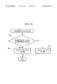
- FIG. 11 is a flowchart of the SRS data communication process shown in FIG. 7 .
- FIG. 12 is the circuit diagram of an airbag apparatus in a conventional example.
- FIG. 13 is the circuit diagram of an improved airbag apparatus in a conventional example.
- FIG. 14 is a diagram explaining the seating condition of a passenger seated on the seat.
- the basic principle of the passenger detection system according to the present invention will be explained with reference to FIGS. 1A and 1B.
- the present detection system is based on perturbations in a weak electric field generated by the presence of an object in the vicinity of an antenna electrode.
- FIG. 1A when a high frequency low voltage (HFLV) signal is applied to an antenna electrode E 1 by an oscillation circuit OSC, a weak electric field is generated in the vicinity of the electrode, resulting in a flow of (transmission) current I in the antenna electrode E 1 .
- HFLV high frequency low voltage
- FIG. 1B When an object OB is introduced in the vicinity of the antenna electrode E 1 , as shown in FIG. 1B, the electric field is disturbed, resulting in generation of current I 1 at the antenna electrode E 1 side, which is different in character than current I.
- antenna electrode E 1 depending on presence/absence of object OB on a seat of the automobile, it is possible to detect the seating condition of the passenger. More specifically, by increasing the number of antenna electrodes, much more precise information can be gained on the object, including a passenger, that occupies the seat so that the condition of the passenger can be much more precisely detected.
- FIGS. 2A, 2 B, to 5 The parts of the present system which are the same as those in the conventional systems shown in FIGS. 12 to 14 are referenced using the same reference numerals and their detailed explanations are omitted.
- FIGS. 2A, 2 B, 3 A, and 3 B show the structures of the driver's or front passenger's seat 1 , which is comprised primarily of sitting section 1 a , backrest section 1 b , and seat supporting section 1 c.
- the sitting section 1 a is typically comprised by a seat frame 3 fixed to a base 2 that is slidable forward and backward, a cushion part disposed above the seat frame 3 , and an outer covering for the cushion part.
- the backrest section 1 b is typically comprised by a cushion part disposed on the front side of the seat frame 3 and an outer covering for the cushion part.
- This backrest section 1 b has a plurality of strip antenna electrodes 4 ( 4 a 4 b , . . . 4 f ) arranged in the substantially horizontal direction and having spacing between each two electrodes. These antenna electrodes are long enough to occupy a wide area in the cross direction of the backrest section 1 b .
- the seat supporting section 1 c at the door side has a strip antenna electrode 4 g arranged in the vertical direction.
- antenna electrodes 4 it is possible to install the antenna electrodes 4 on the outside or inside of the covering or on the covering part itself. Also, a plurality of antenna electrodes 4 g may be provided, or the above antenna electrode 4 g may be divided into elements in the vertical direction in the seat supporting section 1 c . Furthermore, control unit 10 (explained later) is provided on the seat frame 3 and in the vicinity thereof (for example, the inside of the backrest section 1 b ).
- the antenna electrodes 4 are made of a conductive fabric or the like, but they may be made by weaving a metallic thread in the seat fabric of the backrest section 1 b and seat supporting section 1 c or applying a conductive paint or using metal strips in the seat fabric.
- the strip antenna electrodes 4 a , 4 b , . . . , 4 f have the same size (e.g., width: 30 mm, length: 280 mm). As shown in FIGS. 3A and 3B, it is preferable that the antenna electrodes 4 a , 4 b , . . . , 4 f be constructed by arranging these separate strip electrodes as a unit on one surface of a base member 5 made of an insulating material, having specified spacing (e.g., 10 mm) between the electrodes in the vertical direction. This unit is placed inside of the outer covering part of the backrest section 1 b.
- the size of the antenna electrode 4 g is smaller than that of the antenna electrodes 4 a , 4 b , . . . , 4 f and is positioned at one of the sides of the seat supporting section 1 c , which face inward towards each other.
- Lead wires 6 i.e., 6 a , 6 b , . . . , 6 g
- These lead wires are respectively connected to connectors (or terminals) 19 a , 19 b , . . . , 19 g of the control unit 10 explained later.
- the control unit 10 is comprised by: an oscillation circuit (corresponding to the voltage generation means of the present invention) 11 for generating a high-frequency (e.g., about 120 kHz) and low-voltage (e.g., about 5 to 12 V) signal; an amplitude control circuit 12 for controlling the amplitude of the transmission signal output from the oscillation circuit 11 to be approximately constant; a current detection circuit 15 (corresponding to the current detection means of the present invention) for detecting the current of the transmission signal; an AC-DC conversion circuit 16 for converting the output signal from the current detection circuit 15 to direct current; an amplifier 17 for amplifying the output signal from the AC-DC conversion circuit 16 ; a switching circuit 18 , having a plurality of switching devices 18 a , 18 b , .
- an oscillation circuit corresponding to the voltage generation means of the present invention
- amplitude control circuit 12 for controlling the amplitude of the transmission signal output from the oscillation circuit 11 to be approximately constant
- a current detection circuit 15 corresponding to the current detection means of
- An airbag apparatus 30 having the structure as shown in FIG. 5 is connected with the control circuit 20 of the above control unit 10 .
- This airbag apparatus 30 comprises main airbag unit MA typically positioned in front of the driver's and front passenger's seats, side airbag unit SA typically positioned at the door side of the driver's and front passenger's seats, control circuit CC, and electronic accelerometer (impact sensor) GS.
- the side airbag unit SA may be provided for any one of the driver's and front passenger's seats.
- amplitude control circuit 12 typically comprises amplitude varying circuit 13 for varying the voltage amplitude of transmission signals and amplitude detection circuit 14 for detecting the voltage amplitude of the transmission signals.
- the amplitude varying circuit 13 typically has amplitude varying section 13 a including a programmable gain amplifier (PGA), while the amplitude detection circuit 14 typically has voltage amplitude detecting section 14 a including an operational amplifier and others, AC-DC conversion circuit 14 b for converting the output signal from the amplitude detection circuit 14 a to direct current, and amplifier 14 c for amplifying the output signal from the AC-DC conversion circuit 14 b .
- the output signal from the amplifier 14 c is supplied to the control circuit 20
- the amplitude varying signal for the amplitude varying section 13 a is output from the control circuit 20 .
- the current detection circuit 15 in the control unit 10 typically includes an impedance element, for example resistor 15 a , connected in series to the signal circuit (i.e., transmission signal side) and an amplifier 15 b , such as a differential amplifier, for amplifying the terminal voltage of the resistor 15 a .
- the output side of the current detection circuit 15 is connected to the control circuit 20 through the AC-DC conversion circuit 16 and the amplifier 17 .
- the output side of the resistor 15 a in the current detection circuit 15 is connected to the connectors 19 a , 19 b , . . . , 19 g through the switching circuit 18 .
- the passenger detection system having the above structure operates in the following manner.
- the oscillation circuit 11 generates an HFLV signal whose voltage amplitude is detected by the detection section 14 a of the amplitude detection circuit 14 , and the detection signal is converted to a DC signal in the AC-DC conversion circuit 14 b .
- the converted signal is then amplified in the amplifier 14 c , and the amplified signal is input in the control circuit 20 .
- the control circuit 20 judges whether the detected voltage amplitude meets the required amplitude value, and sends an amplitude varying signal to the amplitude varying section 13 a so as to correct the amplitude to the required value.
- This process controls the voltage amplitude of the transmission signal at a specific voltage amplitude, and henceforth, voltage amplitude of the transmission signal is corrected to the specific voltage amplitude by the linked action of the amplitude varying circuit 13 and the amplitude detection circuit 14 .
- the transmission signal having a constant voltage amplitude in the above way is applied to antenna electrodes 4 through the current detection circuit 15 , switching circuit 18 , and the connectors, resulting in the generation of a weak electric field in the vicinity of the antenna electrodes 4 .
- switching circuits 18 are operated by signals from the control circuit 20 so that, first, only the switching device 18 a is closed, next only the switching device 18 b is closed, next only the switching circuit 18 c is closed, and such a stepwise switching is successively carried out so that when a particular switch is being closed, the other switches are all opened.
- the constant-amplitude transmission signal passes through current detection circuit 15 , the particular switching device (one of 18 a to 18 g ), a particular connector (one of 19 a to 19 g corresponding to the particular switching device), and reaches a particular antenna electrode (one of 4 a to 4 g corresponding to the particular switching device), generating a weak electric field in the vicinity of the particular antenna electrode (one of 4 a to 4 g ), so that a specific value of current, governed by the seating condition of passenger P seated on seat 1 , flows in the relevant antenna electrode.
- the current corresponds to the dielectric constant of the relevant body part of the passenger, such as the back, the shoulder, the neck, or the head, and to the distance between the passenger and the seat supporting section 1 c .
- the above current is detected by the current detection circuit 15 , converted to a DC signal in the AC-DC conversion circuit 16 , amplified in the amplifying circuit 17 and is successively input in the control circuit 20 .
- the sequence of switching may be in a reverse direction, 18 g , 18 f , . . . to 18 a.
- reference data are already stored such as threshold value (data) regarding the head position of passenger P who is seated on seat 1 , and another threshold value (data) regarding distance conditions of passenger P with respect to the seat supporting section 1 c , that is, how close the passenger is to antenna electrode 4 g.
- the threshold value data regarding the head position are selected as follows. If an adult or child passenger is seated on the seat 1 , the transmission current level to each antenna electrode is specified depending on the dielectric constant of the relevant body part of the passenger, such as the head, the neck, the shoulder, or the back, that is, a portion below the shoulder generates the highest level, the head generates the second highest level, while the neck generates the lowest level. Therefore, using the level difference of the transmission current between the shoulder and the neck, the shoulder line of the passenger can be detected.
- the upper part above the shoulder line can be determined as the head part; thus, the threshold value regarding the head position is determined at the center position (i.e., height) between the position (i.e., height) of the antenna electrode which faces the shoulder of an adult and the position (i.e., height) of the antenna electrode which faces the shoulder of a child.
- the threshold value regarding the distance conditions of passenger P to antenna electrode 4 g can be determined with reference to the seating condition of passenger P as shown using dotted lines in FIG. 6, observed when the passenger leans on the seat supporting section 1 c .
- a seating condition is the worst or most limiting condition for deploying the side airbag.
- the threshold value is determined based on data corresponding to the current flowing through antenna electrode 4 g in the above seating condition.
- signal data here, head position data
- threshold data garding the head position
- signal data regarding the leaning condition on the seat supporting section 1 c are compared with the threshold data (regarding the leaning condition) stored in advance in the control circuit 20 , so that it is determined whether the passenger leans against the seat supporting section 1 c .
- the side airbag unit SA in the airbag apparatus 30 is placed in the deployable or non-deployable state by the transmission signal from control circuit 20 .
- the transmission signal from the control circuit 20 is input in the control circuit CC of the airbag apparatus 30 . If it is determined that the passenger P leans against the seat supporting section 1 c beyond the limit, a command is set so as not to supply a gate signal to, for example, switching device SW 4 at the front passenger's seat when the relevant side of the automobile crashes into something, while if it is determined that the passenger P does not lean against the seat supporting section 1 c beyond the limit, a command is set so as to supply a gate signal to the switching device SW 4 .
- step S 1 the process (i.e., the program) is initialized, and proceeds to step S 2 .
- step S 2 initial diagnostics are performed for the communication system between the control circuit 20 and the airbag apparatus 30 .
- step S 3 it is examined whether the engine is operating, and if it is judged that the engine is operating, it proceeds to step S 4 . If it is determined that the engine is not operating, this determination step is repeated.
- step S 4 signal data (i.e., head position data) related to the current around a particular antenna electrode and signal data related to the seating condition of passenger P on seat 1 , resulting from the application of a weak electric field on the particular antenna electrode of the antenna electrodes 4 , are received.
- signal data i.e., head position data
- step S 5 based on the received data, it is determined (i) presence/absence of the passenger in the seat, (ii) whether the passenger is an adult, and (iii) the seating condition of the passenger (i.e., the leaning condition against the seat supporting section 1 c ).
- step S 6 based on the results obtained by step S 5 , “SRS communication” is carried out between the control circuit 22 and the airbag apparatus (called SRS) 30 .
- step SRS airbag apparatus
- step SA 1 stored data (here, fixed data) are sent from the control circuit 20 to the control circuit CC in the airbag circuit 30 .
- step SA 2 transmission data are received by the control circuit 20 from the airbag apparatus 30 .
- step SA 3 it is examined by control circuit 20 whether the received data from the airbag apparatus 30 match the data sent from the control circuit 20 to the airbag apparatus 30 . If it is judged that the data are matched, the process is continued. If the data do not match, it is judged that problems exist in the communication system and a fail-safe process is carried out and an alert lamp or a warning lamp is turned on, for example.
- the initial diagnostics may be carried out by sending stored or fixed data from the airbag apparatus 30 to the control circuit 20 which then sends corresponding data, so that matching process can be carried out in the control circuit CC in the airbag apparatus 30 .
- step SB 1 one switching device at one time is selected from the switching devices 18 a to 18 g by using the control signal from the control circuit 20 , so that only the switching circuit 18 a is closed, for example, to select an antenna electrode 4 a . That is, one of the switching devices 18 a to 18 g is selectively closed in turn, such as 18 a , 18 b , 18 c , . . . , so that a corresponding antenna electrode 4 a 4 b , 4 c , . . . , is selected in turn.
- step SB 2 data of the transmission signal to the target antenna electrode is received in the control circuit 20 .
- step SB 3 it is examined whether successive selection of antenna electrodes 4 a to 4 g by the successive actions of the switching devices 18 a to 18 g has been completed. If it is judged that the switching process has been completed, it proceeds to the passenger evaluation process. If it is judged that the switching process is incomplete, it returns to step SB 1 .
- step SC 1 the transmission signal data sent to the antenna electrode 4 g and the threshold value data related to the leaning condition (against seat supporting section 1 c ) of the passenger, stored in advance in the control circuit 20 , are compared so as to determine whether passenger P seated on seat 1 leans against the seat supporting section 1 c . If the transmission signal data received by the antenna electrode 4 g is equal to or greater than the threshold value, then it is determined that the passenger P leans against the seat supporting section 1 c , and the process proceeds to step SC 2 . In step SC 2 , OFF-data for not deploying the side airbag unit are entered in the SRS, and the program continued.
- step SC 1 if the transmission signal data sent to the antenna electrode 4 g is smaller than the threshold value, it is determined that the passenger P does not lean against the seat supporting section 1 c , and the process proceeds to step SC 3 .
- step SC 3 ON-data for deploying the side airbag unit are entered in the SRS, and the program connects to the SRS communication process.
- the following operational flow may be added to the above passenger evaluation process:
- signal data sent to the antenna electrodes 4 a to 4 f and the threshold value data for recognizing the shoulder line of the passenger are compared to extract an antenna electrode having transmission signal data which is equal to or greater than the relevant threshold value.
- the head position is detected based on the position of the extracted antenna electrode, and the process proceeds to the third step.
- the detected head position is compared with the threshold value data (with respect to the head position) stored in advance in the control circuit 20 so as to determine whether the passenger seated on seat 1 is an adult. If the passenger is determined to be an adult P, then the process proceeds to the fourth step, where ON-data for deploying the main airbag unit in the airbag apparatus 30 is installed, and the process then proceeds to the SRS data communication flow.
- the main airbag unit is provided at the dash board or the handle.
- the process proceeds to the fifth step, where OFF-data for not deploying the main airbag unit in the airbag apparatus 30 is installed, and the program is continued.
- step SD 1 ON-data for placing the airbag in the airbag apparatus 30 in the deployable state or OFF-data for placing the airbag in the non-deployable state and system check-data are sent from the passenger detection unit circuitry (i.e., control circuit 20 ) to the airbag apparatus circuitry (i.e., control circuit CC).
- the passenger detection unit circuitry i.e., control circuit 20
- the airbag apparatus circuitry i.e., control circuit CC
- step SD 2 (system) OK-data or (system) NG-data in response to the ON-data or OFF-data and the system check-data from the airbag apparatus are received by the control circuit 20 , and it proceeds to step SD 3 .
- step SD 3 it is judged whether the ON-/OFF-data and system check-data, which had been sent from the passenger detection side to the airbag apparatus side, are again returned from the airbag apparatus circuitry to the passenger detection side in the normal condition.
- step SD 4 it is examined whether the fail-safe timer is at zero.
- This detection process of communication system problems is, for example, programmed to repeat three times. Therefore, if it is judged that the fail-safe timer is zero, a fail-safe process is carried out, and an alert lamp is activated, for example. If it is judged that the fail-safe timer is not at zero, it proceeds to step SD 5 , and a fail-safe timer count is performed, and the process is continued.
- step SE 1 the airbag apparatus circuitry (i.e., control circuit CC) receives ON-data for placing the airbag apparatus in the deployable state or OFF-data for placing the airbag apparatus in the non-deployable state and system check-data from the passenger detection unit circuitry (i.e., control circuit 20 ).
- the airbag apparatus circuitry i.e., control circuit CC
- step SE 2 the received data are checked to examine whether or not they are normal. In either case, it proceeds to step SE 3 for sending OK-data or NG-data and system check-data to the passenger detection unit circuitry.
- step SE 2 If it is judged, in step SE 2 , that the communication system is normally operated, OK-data are sent in step SE 3 , and it proceeds to step SE 4 .
- step SE 4 the data on the airbag side is renewed in response to the OK-data, thereby enabling to place the airbag in the deployable state or non-deployable state.
- step SE 2 If, in step SE 2 , it is judged that there is a problem in the communication system, NG-data are sent to the control circuit 20 in step SE 3 , and it proceeds to step SE 5 .
- step SE 5 it is examined whether the fail-safe timer is at zero. This detection process of circuit problems is programmed to repeat three times, for example. Therefore, if it is judged that the fail-safe timer is zero, a fail-safe process is carried out, and an alert lamp is activated, for example. If it is judged that the fail-safe timer is not at zero, it proceeds to step SE 6 , and a fail-safe timer count is performed, and the process is continued.
- antenna electrode 4 g is disposed at the seat supporting section 1 c at the door side of seat 1 , and the high frequency low voltage (HFLV) signal is applied to the antenna electrode 4 g , thereby generating a weak electric field around this antenna electrode. Accordingly, a current corresponding to the seating condition of passenger P seated on seat 1 , that is, the leaning condition with respect to the seat supporting section 1 c , flows in the antenna electrode 4 g.
- HFLV high frequency low voltage
- the current level is higher, while if the passenger P is not in contact with the seat supporting section 1 c as shown by the solid lines in FIG. 6 (that is, in the normal seating condition), the current level is lower. Accordingly, it is possible to detect the normal/abnormal posture of passenger P with respect to the seat supporting section 1 c by referring to the above current level.
- the side airbag unit in the airbag apparatus 30 is set to one of the deployable and non-deployable states according to the seating condition of the passenger seated on seat 1 . If it is judged that passenger P leans against the seat supporting section 1 c heavily, the side airbag of airbag apparatus 30 is set in the non-deployable state. Therefore, even if the relevant side of the automobile crashes into something, the side airbag does not deploy; thus, it is possible to prevent the passenger from suffering secondary damage which accompanies the deployment of the side airbag.
- a plurality of strip antenna electrodes 4 are provided over a wide range along the substantially horizontal direction of the section 1 b , with a spacing to each other in the vertical direction.
- a high frequency low voltage (HFLV) signal is applied to each antenna electrode in turn, so that a weak electrical field is generated in the relevant antenna electrode.
- the antenna electrodes 4 ( 4 a to 4 f ) facing body parts of the passenger such as the head, neck, shoulder, and back respectively get specific currents corresponding to the dielectric constants related to each body part.
- the shoulder line can be extracted with reference to the above currents so as to detect the head position, thereby easily determining whether the passenger seated on the seat is an adult. Based on the above determination, it is possible to set the main airbag of the airbag apparatus 30 to the deployable or non-deployable state.
- the system cost can be lowered significantly by providing the system power source (used in control unit 10 ) from the single power source produced by the electric power circuit 22 , and by producing an HFLV and approximately rectangular waveform with the use of only the positive power source in the oscillation circuit 11 .
- the circuit arrangement of each unit as well as the electric power circuit 22 and the oscillation circuit 11 can be simplified.
- the amplitude control circuit 12 is used to maintain the amplitude of the voltage impressed on the antenna electrodes 4 ( 4 a to 4 g ) approximately constant, so that the data related to the current detected by the electric current detection circuit 15 can be compared readily with the threshold value data relating to the head position and seating condition (i.e., the leaning condition against the seat supporting section) of the passenger, and the following judgment can also be performed easily. Therefore, detection with a high degree of accuracy and reliability can be realized.
- the voltage generation means for generating an HFLV signal (which comprises an oscillation circuit) may also include an HFLV source to produce an approximately rectangular waveform by only using a positive electrical power source and by ON/OFF controlling a switching device based on clock signals in the control circuit.
- An output frequency other than 120 KHz may be chosen depending on the conditions inside the automobile, and the voltage may be selected outside the range of 5 to 12 volts.
- the current detection circuit is not limited to the embodied example.
- the amplitude control circuit may be omitted depending on the precision of the system power source and expected performance level of the system.
Abstract
Description
Claims (4)
Applications Claiming Priority (2)
| Application Number | Priority Date | Filing Date | Title |
|---|---|---|---|
| JP25712298A JP3347071B2 (en) | 1998-09-10 | 1998-09-10 | Occupant detection system |
| JP10-257122 | 1998-09-10 |
Publications (1)
| Publication Number | Publication Date |
|---|---|
| US6263271B1 true US6263271B1 (en) | 2001-07-17 |
Family
ID=17302044
Family Applications (1)
| Application Number | Title | Priority Date | Filing Date |
|---|---|---|---|
| US09/394,005 Expired - Lifetime US6263271B1 (en) | 1998-09-10 | 1999-09-10 | Passenger detection system comprising side airbag which is deployable or non-deployable according to seating condition |
Country Status (2)
| Country | Link |
|---|---|
| US (1) | US6263271B1 (en) |
| JP (1) | JP3347071B2 (en) |
Cited By (16)
| Publication number | Priority date | Publication date | Assignee | Title |
|---|---|---|---|---|
| US6371513B1 (en) * | 1998-09-16 | 2002-04-16 | Toyota Jidosha Kabushiki Kaisha | Side airbag apparatus |
| US6402240B1 (en) * | 1999-07-16 | 2002-06-11 | Ts Tech Co., Ltd. | Seat having passenger's sitting posture detecting apparatus, and harness wiring structure in seat |
| US6556137B1 (en) * | 1998-07-28 | 2003-04-29 | Nec Corp. | Passenger detecting system and air bag apparatus using the same |
| US20030083795A1 (en) * | 2001-10-31 | 2003-05-01 | Automotive Systems Laboratory, Inc. | Occupant detection system |
| US6577023B1 (en) | 1998-12-30 | 2003-06-10 | Automotive Systems Laboratory, Inc. | Occupant detection system |
| US20030182042A1 (en) * | 2002-03-19 | 2003-09-25 | Watson W. Todd | Vehicle rollover detection system |
| US6684973B2 (en) * | 2000-09-29 | 2004-02-03 | Honda Elesys Co., Ltd. | Occupant detecting apparatus capable of improving detection accuracy |
| US20040113634A1 (en) * | 2000-05-26 | 2004-06-17 | Automotive Systems Laboratory, Inc. | Occupant sensor |
| US6825765B2 (en) | 1998-12-30 | 2004-11-30 | Automotive Systems Laboratory, Inc. | Occupant detection system |
| US20050010345A1 (en) * | 2001-07-26 | 2005-01-13 | Wolfgang Drobny | Arrangement with a control device and a state detection device, in addition to a method for testing/diagnosing said type of arrangement |
| US20050121891A1 (en) * | 2003-12-03 | 2005-06-09 | Milliken & Company | Airbag having conductive material and system and method for adjustment of deployment characteristics of airbag having conductive material |
| EP1688313A1 (en) * | 2005-02-02 | 2006-08-09 | Methode Electronics International GmbH | Sensor device for detecting the occupants of a vehicle |
| US20080157510A1 (en) * | 1994-05-09 | 2008-07-03 | Automotive Technologies International, Inc. | System for Obtaining Information about Vehicular Components |
| US20090243350A1 (en) * | 2008-03-31 | 2009-10-01 | Honda Giken Kogyo Kabushiki Kaisha | Vehicle seat with a temperature control unit |
| US7887089B2 (en) | 1992-05-05 | 2011-02-15 | Automotive Technologies International, Inc. | Vehicular occupant protection system control arrangement and method using multiple sensor systems |
| US9475438B2 (en) | 2014-11-14 | 2016-10-25 | Intelligent Technologies International, Inc. | Wireless switches using human body as a conductor |
Families Citing this family (2)
| Publication number | Priority date | Publication date | Assignee | Title |
|---|---|---|---|---|
| EP1857330B1 (en) * | 2006-05-17 | 2009-11-25 | Hitachi Computer Products (Europe) S.A.S. | Method for determining the morphology of an occupant in an automotive seat with capacitive sensors |
| JP5135242B2 (en) * | 2009-01-22 | 2013-02-06 | 本田技研工業株式会社 | Vehicle occupant detection device |
Citations (8)
| Publication number | Priority date | Publication date | Assignee | Title |
|---|---|---|---|---|
| JPH0665532A (en) | 1992-08-20 | 1994-03-08 | Mitsubishi Kasei Corp | Coating film remover |
| US5464246A (en) * | 1993-02-19 | 1995-11-07 | Simula Inc. | Inflatable tubular cushions for crash protection of seated automobile occupants |
| US5525843A (en) | 1994-02-14 | 1996-06-11 | Ab Volvo | Seat occupant detection system |
| US5524924A (en) * | 1993-11-15 | 1996-06-11 | Trw Vehicle Safety Systems Inc. | Method and apparatus for restraining an occupant of a vehicle upon a side impact against the vehicle |
| US5948031A (en) * | 1996-02-23 | 1999-09-07 | Nec Technologies, Inc. | Vehicle passenger sensing system and method |
| US6018693A (en) * | 1997-09-16 | 2000-01-25 | Trw Inc. | Occupant restraint system and control method with variable occupant position boundary |
| US6126194A (en) * | 1997-03-31 | 2000-10-03 | Simula, Inc. | Inflatable tubular torso restraint system |
| US6179326B1 (en) * | 1995-10-30 | 2001-01-30 | Automotive Technologies International, Inc. | Efficient airbag system |
-
1998
- 1998-09-10 JP JP25712298A patent/JP3347071B2/en not_active Expired - Fee Related
-
1999
- 1999-09-10 US US09/394,005 patent/US6263271B1/en not_active Expired - Lifetime
Patent Citations (9)
| Publication number | Priority date | Publication date | Assignee | Title |
|---|---|---|---|---|
| JPH0665532A (en) | 1992-08-20 | 1994-03-08 | Mitsubishi Kasei Corp | Coating film remover |
| US5464246A (en) * | 1993-02-19 | 1995-11-07 | Simula Inc. | Inflatable tubular cushions for crash protection of seated automobile occupants |
| US5524924A (en) * | 1993-11-15 | 1996-06-11 | Trw Vehicle Safety Systems Inc. | Method and apparatus for restraining an occupant of a vehicle upon a side impact against the vehicle |
| US5525843A (en) | 1994-02-14 | 1996-06-11 | Ab Volvo | Seat occupant detection system |
| JPH09509118A (en) | 1994-02-14 | 1997-09-16 | アーベー ボルボ | Seat occupant detection system |
| US6179326B1 (en) * | 1995-10-30 | 2001-01-30 | Automotive Technologies International, Inc. | Efficient airbag system |
| US5948031A (en) * | 1996-02-23 | 1999-09-07 | Nec Technologies, Inc. | Vehicle passenger sensing system and method |
| US6126194A (en) * | 1997-03-31 | 2000-10-03 | Simula, Inc. | Inflatable tubular torso restraint system |
| US6018693A (en) * | 1997-09-16 | 2000-01-25 | Trw Inc. | Occupant restraint system and control method with variable occupant position boundary |
Cited By (23)
| Publication number | Priority date | Publication date | Assignee | Title |
|---|---|---|---|---|
| US7887089B2 (en) | 1992-05-05 | 2011-02-15 | Automotive Technologies International, Inc. | Vehicular occupant protection system control arrangement and method using multiple sensor systems |
| US20080157510A1 (en) * | 1994-05-09 | 2008-07-03 | Automotive Technologies International, Inc. | System for Obtaining Information about Vehicular Components |
| US6556137B1 (en) * | 1998-07-28 | 2003-04-29 | Nec Corp. | Passenger detecting system and air bag apparatus using the same |
| US6371513B1 (en) * | 1998-09-16 | 2002-04-16 | Toyota Jidosha Kabushiki Kaisha | Side airbag apparatus |
| US6577023B1 (en) | 1998-12-30 | 2003-06-10 | Automotive Systems Laboratory, Inc. | Occupant detection system |
| US6825765B2 (en) | 1998-12-30 | 2004-11-30 | Automotive Systems Laboratory, Inc. | Occupant detection system |
| US6402240B1 (en) * | 1999-07-16 | 2002-06-11 | Ts Tech Co., Ltd. | Seat having passenger's sitting posture detecting apparatus, and harness wiring structure in seat |
| US20040113634A1 (en) * | 2000-05-26 | 2004-06-17 | Automotive Systems Laboratory, Inc. | Occupant sensor |
| US20040075259A1 (en) * | 2000-09-29 | 2004-04-22 | Honda Elesys Co., Ltd. | Occupant detecting apparatus capable of improving detection accuracy |
| US6684973B2 (en) * | 2000-09-29 | 2004-02-03 | Honda Elesys Co., Ltd. | Occupant detecting apparatus capable of improving detection accuracy |
| US6966577B2 (en) | 2000-09-29 | 2005-11-22 | Honda Elesys Co., Ltd. | Occupant detecting apparatus capable of improving detection accuracy |
| US20050010345A1 (en) * | 2001-07-26 | 2005-01-13 | Wolfgang Drobny | Arrangement with a control device and a state detection device, in addition to a method for testing/diagnosing said type of arrangement |
| US7551998B2 (en) * | 2001-07-26 | 2009-06-23 | Robert Bosch Gmbh | System having a control unit and a status acquisition device as well as a method for testing/diagnosing such a system |
| EP1449115A2 (en) * | 2001-10-31 | 2004-08-25 | AUTOMOTIVE SYSTEMS LABORATORY, INC. (a Michigan corporation) | Transaction verification systems and method |
| EP1449115A4 (en) * | 2001-10-31 | 2005-01-26 | Automotive Systems Lab Inc A M | Transaction verification systems and method |
| US20030083795A1 (en) * | 2001-10-31 | 2003-05-01 | Automotive Systems Laboratory, Inc. | Occupant detection system |
| US20030182042A1 (en) * | 2002-03-19 | 2003-09-25 | Watson W. Todd | Vehicle rollover detection system |
| US7698036B2 (en) | 2002-03-19 | 2010-04-13 | Automotive Systems Laboratory, Inc. | Vehicle rollover detection system |
| US20050121891A1 (en) * | 2003-12-03 | 2005-06-09 | Milliken & Company | Airbag having conductive material and system and method for adjustment of deployment characteristics of airbag having conductive material |
| EP1688313A1 (en) * | 2005-02-02 | 2006-08-09 | Methode Electronics International GmbH | Sensor device for detecting the occupants of a vehicle |
| US20090243350A1 (en) * | 2008-03-31 | 2009-10-01 | Honda Giken Kogyo Kabushiki Kaisha | Vehicle seat with a temperature control unit |
| US9475438B2 (en) | 2014-11-14 | 2016-10-25 | Intelligent Technologies International, Inc. | Wireless switches using human body as a conductor |
| US10033381B2 (en) | 2014-11-14 | 2018-07-24 | Intelligent Technologies International, Inc. | Wireless switches using human body as a conductor |
Also Published As
| Publication number | Publication date |
|---|---|
| JP3347071B2 (en) | 2002-11-20 |
| JP2000088968A (en) | 2000-03-31 |
Similar Documents
| Publication | Publication Date | Title |
|---|---|---|
| US6263271B1 (en) | Passenger detection system comprising side airbag which is deployable or non-deployable according to seating condition | |
| JP3346464B2 (en) | Occupant detection system and occupant detection method | |
| US5411289A (en) | Air bag system for a motor vehicle | |
| US6960841B2 (en) | Passenger detection system and detection method | |
| US6310407B1 (en) | Passenger detecting system and air bag system using the same | |
| JP3358517B2 (en) | Occupant detection system and occupant detection method | |
| JP3347069B2 (en) | Occupant detection system | |
| US6209910B1 (en) | Ignition control system for a passive safety device | |
| JP3458323B2 (en) | Occupant detection system | |
| JP3394967B2 (en) | Occupant detection system | |
| JP3329370B2 (en) | Occupant detection system | |
| JP3482590B2 (en) | Occupant detection method in occupant detection system | |
| JP3553379B2 (en) | Occupant detection system and occupant detection method | |
| JP3287314B2 (en) | Occupant detection system and occupant detection method | |
| JP3322297B2 (en) | Occupant detection system and occupant detection method | |
| JP3346456B2 (en) | Occupant detection system | |
| JP3235657B2 (en) | Occupant detection system | |
| JP3739930B2 (en) | Occupant detection system and occupant detection method | |
| JPH11198705A (en) | Occupant detection device | |
| JP3476682B2 (en) | Occupant detection system and occupant detection method | |
| JP2000025560A (en) | Occupant detection system | |
| JP3476681B2 (en) | Occupant detection system and occupant detection method | |
| JP2001294117A (en) | Seating detection device for occupant | |
| JP3322296B2 (en) | Occupant detection system and occupant detection method | |
| JP2000153749A (en) | Occupant detection system |
Legal Events
| Date | Code | Title | Description |
|---|---|---|---|
| AS | Assignment |
Owner name: NEC CORPORATION, JAPAN Free format text: ASSIGNMENT OF ASSIGNORS INTEREST;ASSIGNORS:OKA, YOSHITAKA;FUKUI, TSUTOMU;KOYOTA, NOBUHIRO;AND OTHERS;REEL/FRAME:010358/0433 Effective date: 19991021 Owner name: HONDA GIKEN KOGYO KABUSHIKI KAISHA, JAPAN Free format text: ASSIGNMENT OF ASSIGNORS INTEREST;ASSIGNORS:OKA, YOSHITAKA;FUKUI, TSUTOMU;KOYOTA, NOBUHIRO;AND OTHERS;REEL/FRAME:010358/0433 Effective date: 19991021 |
|
| STCF | Information on status: patent grant |
Free format text: PATENTED CASE |
|
| FEPP | Fee payment procedure |
Free format text: PAYOR NUMBER ASSIGNED (ORIGINAL EVENT CODE: ASPN); ENTITY STATUS OF PATENT OWNER: LARGE ENTITY |
|
| AS | Assignment |
Owner name: HONDA ELESYS CO., LTD., JAPAN Free format text: ASSIGNMENT OF ASSIGNORS INTEREST;ASSIGNOR:NEC CORPORATION;REEL/FRAME:013484/0602 Effective date: 20021107 |
|
| FPAY | Fee payment |
Year of fee payment: 4 |
|
| FPAY | Fee payment |
Year of fee payment: 8 |
|
| FPAY | Fee payment |
Year of fee payment: 12 |